Abstract
This article concerns the issue of adaptive fuzzy command-filtered fixed-time control in the context of a category of nonlinear systems characterized by mismatched disturbances and unknown nonlinear functions. The backstepping-based disturbance observers are created to alleviate the effects of mismatched disturbances and Fuzzy logic systems are brought into play to model those terms that are unknown. To address the complexity explosion issue in traditional backstepping control, this paper utilizes fixed-time command filters (FTCFs) to design a novel control approach. Moreover, filtering error compensation mechanisms are developed to eliminate the errors introduced by the FTCFs. This paper derives a novel adaptive fixed-time control protocol that successfully conquers the difficulties posed by unknown nonlinear functions and mismatched disturbances. The protocol, implemented within a backstepping framework, guarantees the boundedness of all signals and tracking errors within fixed time. The efficacy of the derived control protocol is illustrated through simulation examples.
MSC:
93D40
1. Introduction
The backstepping method has been a key focus of research in the field of nonlinear systems for many years [1,2,3,4,5,6]. However, its limitations in handling uncertain nonlinear systems have led to the development of hybrid approaches, which combine the backstepping technique with approximate methods, including fuzzy logic systems [7] and neural networks [8,9,10,11,12]. A significant challenge in the conventional backstepping method arises from the “explosion of complexity” phenomenon, which occurs when higher-order derivative operators are applied to virtual controllers. This can lead to increased computational burden and even degrade control system performance if not properly addressed. To mitigate the “explosion of complexity” difficulty inherent in the standard backstepping method, command filters are applied to approximate the differential coefficients of virtual controllers in the course of the design procedure [13,14]. Recent studies, such as [15,16], have reported advances in backstepping command-filtered control for systems with both nonlinearities and uncertainties [17]. However, it is essential to note that these control algorithms overlook the impact of disturbances and model uncertainties.
In the field of engineering, disturbances and uncertainties are common [18], particularly in systems like multi-hydraulic manipulator and multi-missiles, which are often subject to mismatched uncertainties, which are common challenges in the field. External influences like parameter variations, wind, and environmental forces can significantly degrade system performance by circumventing the actuator input pathway, thus demanding advanced control strategies to mitigate their impacts [19,20,21]. Lacking an immediate ways to counteract these influences, the presence of feedback controllers act as a catalyst, giving rise to innovative methodologies that are dedicated to strengthening the system’s resilience against uncertainties and unknown disturbances. This not only enhances the overall robustness and reliability of the system but also paves the way for more advanced and efficient operations in the face of complex and unpredictable environments. Meanwhile, recent advancements have brought about effective ways to enhance the system’s robustness when confronted with such challenges. Notable examples include control protocols making use of disturbance observers, terminal sliding-mode control, and . The first method emerges as a promising solution for balancing disturbance rejection and performance. For instance, Ref. [22] utilized a controller that combines terminal sliding-mode control with a disturbance observer to guarantee system stability. This combination offers a powerful tool for addressing complex control problems and achieving reliable performance in various applications. Similarly, an algorithm for containment control of nonlinear multi-agent systems was developed in [23], which is based on a finite-time distributed observer. Ref. [24] offered a means that provides a novel solution to the challenging issue of mismatched disturbances in active anti-disturbance output consensus. By devising this inventive approach, the researchers have opened up new avenues for enhancing the performance and reliability of systems that are prone to such disturbances, potentially leading to more robust and efficient operations. It is worth noting that while these robust control approaches provide stability guarantees, they do not necessarily ensure other desired performance characteristics beyond asymptotic or finite-time stability.
In the realm of tracking problems in nonlinear systems, a rapid convergence rate is extremely crucial in modern complex industrial processes such as those involved in advanced robotics, precision manufacturing, and satellite communication systems, as these areas of modern industry require highly accurate and efficient tracking capabilities. While asymptotic control ways achieve expected outcomes as time approaches infinity, finite-time convergence is crucial for practical applications [25,26,27,28,29]. Finite-time control offers distinct advantages over asymptotic control, including enhanced disturbance rejection, accelerated convergence rates, and increased tracking precision [30,31]. Although initial conditions can be used to evaluate the settling time of the finite-time controller, in reality, this is often hampered by the fact that initial conditions are often uncertain or unknown. For uncertain nonlinear systems, fixed-time control, which is a step forward compared to finite-time control, has been developed. It overcomes the dependence on initial conditions by providing a settling time estimation that is independent of them [32,33,34,35]. While fixed-time control has received extensive research attention, as of now, there is currently no existing work that addresses the control problem of systems featuring mismatched disturbances by employing command filters. Mismatched disturbances pose a significant challenge to the control of these systems. Additionally, the presence of unknown nonlinear terms further complicates the controller design process. This motivated us to undertake the research presented in this paper.
To sum up, this paper is dedicated to the design of a fixed-time control protocol for a category of systems that are accompanied by mismatched disturbances and unknown uncertainties. For the controlled systems, through integrating FTCFs and disturbance observers, this approach is intended to guarantee the practical fixed-time stability, with the aim of achieving a more reliable and efficient control solution by addressing the challenges posed by uncertainties and disturbances in the fixed-time framework. The main contributions of this article are highlighted as follows: (1) A fixed-time control protocol for nonlinear systems is derived in this paper. This protocol is derived to guarantee that the states within the controlled system converge to a small neighborhood of the origin within fixed time, irrespective of the initial conditions. In contrast to finite-time controllers, as demonstrated in [36,37,38], it is known that the convergence time of finite-time control protocols is influenced by the initial conditions. (2) Differing from conventional fixed-time control strategies [39,40,41,42], our approach uniquely addresses the complexities of mismatched disturbances and uncertain functions by leveraging the strengths of disturbance observers, adaptive laws, and Fuzzy logical systems. (3) The command-filtered technique is leveraged to design a novel fixed-time control protocol, which effectively addresses the “explosion of complexity” problem and improves the controller’s applicability by dispensing with the requirement for high-order derivatives.
The remainder of this article is structured as follows. The main findings are demonstrated in Section 2. Simulation results are displayed in Section 3. Finally, we draw conclusions in Section 4.
System Description
This article investigates the nonlinear systems, which are represented by
where , . is the output, and denotes the state. stands for the mismatched disturbances. denotes the unknown nonlinear function.
Control objective: Designing an adaptive fixed-time fuzzy control protocol for the system Equation (1) that has mismatched disturbances, so as to make the closed-loop systems practically fixed-time stable. Moreover, the output y of the systems can track the desired state within fixed time. At the same time, all states in the evolving systems will tend towards to a small area around zero within fixed time.
Lemma 1
([43]). If , , and , we obtain
Lemma 2
([43]). If , , and , we have
Lemma 3
([39]). A nonlinear system can achieve practical stability within fixed time for the system , if there exists a Lyapunov function V such that
where , , , m, , , and . The solution’s residual set is defined by
with . There is a bound on the settling time
The FLSs will be used to approximate the unknown nonlinear terms. The FLSs exhibit the following property.
Lemma 4
([44]). When is a continuous function on a compact set A, given , there are FLSs for which
where g denotes the number of rules, denotes the fuzzy basis faction vector, and θ denotes the optimal parameter vector.
Remark 1.
Among some prior investigations on nonlinear systems, certain constraints are imposed on the nonlinear functions so as to fulfill specific requirements, such as the Lipschitz conditions and quadratic constraints [45,46], which represent a significant restriction on the nonlinear functions that may limit the applicability of the results in some cases, as researchers aim to simplify the analysis and design of controllers for nonlinear systems, but may also lead to conservative results, and may not be suitable for all types of nonlinear systems, thus making it important to explore alternative approaches that do not rely on such restrictive assumptions. However, this paper refrains from imposing any demands for fulfilling these constraints, thereby rendering this description strikingly comprehensive. Furthermore, actual industrial systems are likely to encounter mismatched disturbances. These disturbances have the potential to exert a negative impact on the performance of the control system and may even lead to system instability. As a consequence, considering mismatched disturbances is of utmost significance when designing controllers for these omnipresent systems.
2. Main Results
In this segment, a fixed-time adaptive controller for nonlinear systems will be deduced when they are encountered with uncertainty functions and mismatched disturbances. This can be accomplished through the utilization of the backstepping control strategy, FTCFs, and disturbance observers.
2.1. Fixed-Time Fuzzy Control Law Design
Before designing the control law, a set of new function transformations is defined as
where is the result yielded by the fixed-time command filter (FTCF), which is constructed as
where , , , , , , , the virtual control function is designed later, p denotes a small positive constant, and the outputs are and .
Lemma 5
([47]). The FTCF is designed as Equation (10) to be considered. If the input meets the condition that (where for ), then for any positive value , there exist constants and in such a way that could be obtained in fixed time. Moreover, , , and are bounded in fixed time.
Remark 2.
As is generally acknowledged, in the traditional backstepping technique, imposing a series of differential operations to the virtual controller might lead to the issue of “explosion of complexity”. To address this problem, the FTCFs are utilized. The signal can be obtained without the occurrence of term explosion, using the virtual controller as input. This signal shall be utilized within the framework of the controller design. As a consequence, the occurrence of repeated differentiation may be successfully precluded. We compensate for the filtering errors caused by FTCFs by formulating the function transformation for the derivation of the novel fixed-time control law.
Select the Lyapunov function as
where and , with and being the estimates of and , respectively. and are to be given later. . Then, we have
The term of Equation (13) is described by
By using Equation (14), Equation (13) becomes
According to Lemma 4, the FLSs play a role in approximating as follows
It follows from Equations (15) and (16) that
Define
Construct the disturbance observer as
where , and .
Moreover, the virtual control law and updating law for can be determined by
where , , , , , , , , , and .
The error compensating signal can be defined as
Substituting Equations (19)–(22) into Equation (17), we have
where c is a design parameter, and g denotes the FLSs’ node number.
Step : Select the Lyapunov function as
where the compensated tracking error for is , where is the compensation signal. and , with and being the estimates of and , respectively. , , and are to be given later. . Then, one has
The virtual controller and updating law for can be determined by
where , , , and , with , , and .
The error compensating signal can be defined as
Step : Select the Lyapunov function as
where , and denotes the signal for compensation. and , with and being the estimates of and , respectively. , , and are to be given later. . Moreover, one obtains
Note that there also exists
Construct the disturbance observer as
where , .
The virtual control law and updating law of can be determined by
where , , , and , with , , and .
The error compensating signal can be defined as
Step : Select the Lyapunov function as
where the compensated tracking error for is , and denotes the compensation signal. and , with and being the estimates of and , respectively. , , and are to be given later. and . Moreover, one has
Note that there also exists
Define
Construct the disturbance observer as
where , and ).
According to Equation (48), we have
Then, the actual control law u and update law for can be determined by
where , , , and , with , , and .
The error compensating signal can be defined as
Note that
where the property is utilized.
2.2. Stability Analysis
The major findings of this paper can be summarized in the following theorem.
Theorem 1.
Given the nonlinear system Equation (1), which meets Assumption 1, the actual controller as defined in Equation (52) with the virtual control laws Equations (20), (32) and (42), and the update laws Equations (21), (33), (43) and (53), and disturbances observers Equations (19), (30), (41) and (50) is proposed. The control scheme that is derived ensures the following: the controlled system attains practical fixed-time stability. Moreover, all the signals within the framework of the controlled system are bounded. Additionally, the tracking error remains bounded within fixed time.
Proof.
The proof consists of two components. Part A provides evidence that is bounded at all times. Part B accomplishes the proof pertaining to the tracking control issue.
Part A: Select the Lyapunov function as
Then, we have
According to Young’s inequality, we have
Furthermore, we have
According to Lemma 5, with , one has
where , and .
Furthermore, we have
where is the initial state of . Since , we have for , i.e., the is bounded at all times.
Part B: Since , one has
From Equations (55) and (63), one has
where . According to [48], as is well-known, regarding a bounded function with acting as the constant boundary, when and , we have
where .
Similar to Equation (65), we have
where .
According to Lemma 1, one obtains
Then, we have
where , , , and . , and . Based on Lemma 3, (69) indicates that the controlled system attains practical fixed-time stability, and , , and fall within certain bounds. Moreover, , , and will be located within the area
in a settling time , where .
According to Equation (70), we have
□
The design procedure and key steps of the controller could be visualized from the block diagram shown in Figure 1.
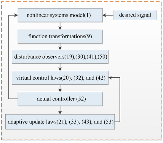
Figure 1.
Block diagram of the fixed-time control scheme.
3. Simulation Example
Two illustrative examples are put forward to demonstrate the efficacy of the derived control protocol in this segment.
Example 1.
We take the following system into consideration, which is represented by
Case 1.
The initial values of the states are and . In this simulation, the reference signal is . The other parameters are designed as , , , , , , , , , , , , , , , , and .
Case 2.
The initial values of the states are and . In this simulation, the reference signal is . The other parameters are designed as , , , , , , , , , , , , , , , , and .
The simulation results for Example 1 are displayed in Figure 2, Figure 3, Figure 4, Figure 5, Figure 6, Figure 7, Figure 8 and Figure 9. Among them, Figure 2, Figure 3, Figure 4 and Figure 5 are for case 1, and Figure 6, Figure 7, Figure 8 and Figure 9 are for case 2. For case 1, the trajectories of states and are shown in Figure 2. Figure 3 gives the trajectory of state . Figure 4 provides the trajectory of the tracking error. Figure 6 gives the trajectories of states and for case 2. Figure 7 displays the trajectory of state . Figure 8 provides the trajectory of the tracking error for case 2. The trajectory of the control signal is presented in Figure 5 and Figure 9 for the two cases. According to simulation results, it can be seen that the fixed-time controller designed in this paper can achieve the tracking control of the desired signal within 25s and the tracking error is less than .
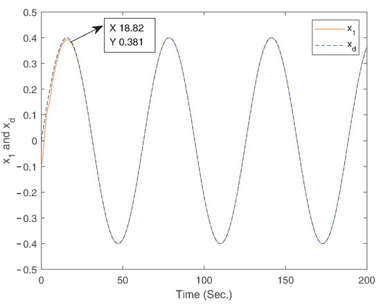
Figure 2.
The trajectories of the states and .
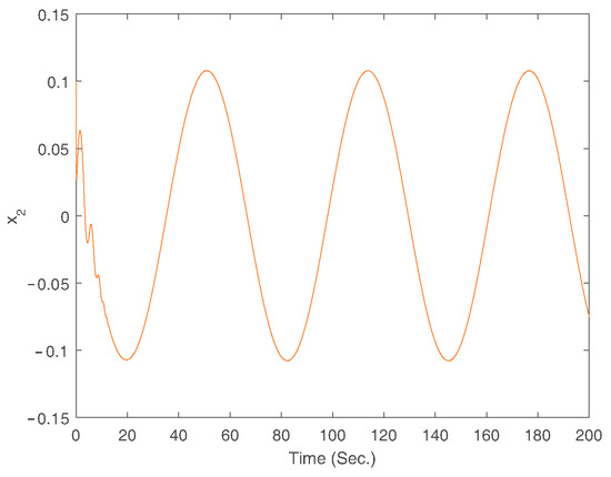
Figure 3.
The trajectory of the state .
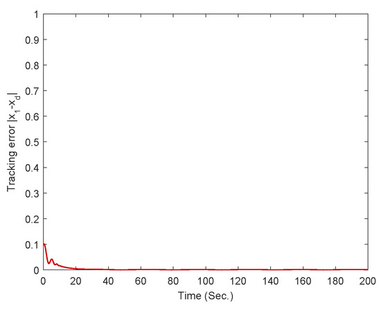
Figure 4.
The trajectory of tracking error .
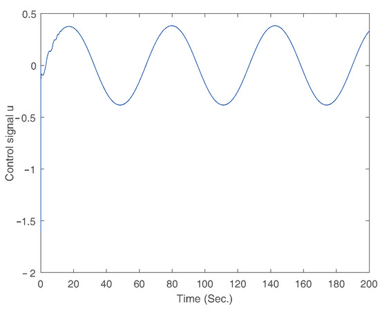
Figure 5.
The trajectory of control signal.
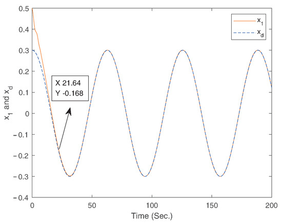
Figure 6.
The trajectories of the states and .
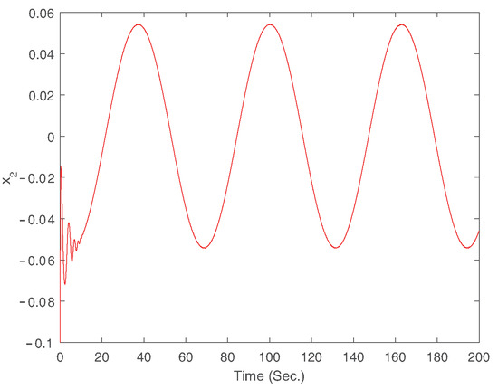
Figure 7.
The trajectory of the state .
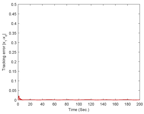
Figure 8.
The trajectory of tracking error .
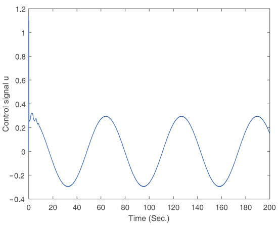
Figure 9.
The trajectory of control signal.
Example 2.
We consider a pulled car system, which can be described as
where and are the external disturbances, is the displacement of the car with respect to the rest position, and is the speed of the car. Ns/m is the damping factor. kg is the mass of the car, and denotes the stiffness of the spring, N/m.
Case 1.
The initial values of the states are and . In this simulation, the reference signal is . The other parameters are designed as , , , , , , , , , , , , , , , , and .
Case 2.
The initial values of the states are and . In this simulation, the reference signal is . The other parameters are designed as , , , , , , , , , , , , , , , , and .
Case 3.
The initial values of the states are and . In this simulation, the reference signal is . The other parameters are designed as , , , , , , , , , , , , , , , , and .
The simulation results for three cases of Example 2 are displayed in Figure 10, Figure 11, Figure 12, Figure 13, Figure 14 and Figure 15. Among them, Figure 10 and Figure 11 are for case 1, Figure 12 and Figure 13 are for case 2, and Figure 14 and Figure 15 are for case 3. The trajectories of states and are shown in Figure 10, Figure 12, and Figure 14. The trajectory of the tracking error is shown in Figure 11, Figure 13, and Figure 15. Based on above simulation results, it can be seen that the fixed-time controller designed in this paper can achieve the tracking control of the desired signal within 25s and the tracking error is less than .
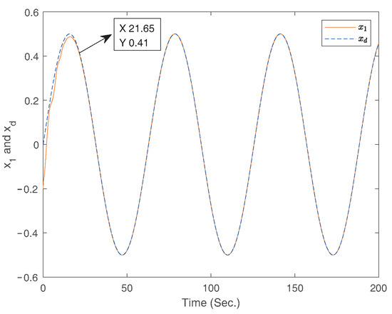
Figure 10.
The curves of the states and for case 1.
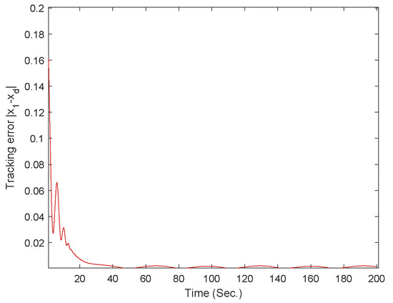
Figure 11.
The curve of the tracking error for case 1.
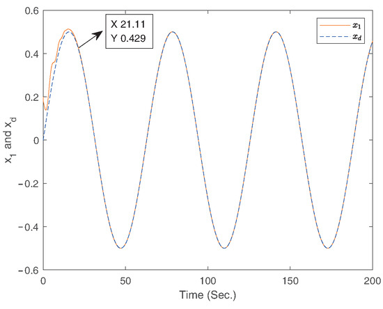
Figure 12.
The curves of the states and for case 2.
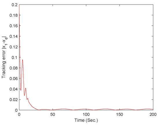
Figure 13.
The curve of the tracking error for case 2.
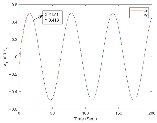
Figure 14.
The curves of the states and for case 3.
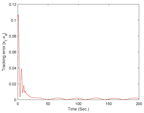
Figure 15.
The curve of the tracking error for case 3.
To better illustrate the effectiveness of the controller designed in this paper, a comparison will be made between the controller designed in this paper and the designed controller in Ref. [49] by Example 2. To ensure the fairness of the comparison, the parameters and states of the system are set to be the same.
In addition, we have also conducted comparative numerical simulation experiments between the fixed-time algorithm designed in this paper and the following finite-time control algorithms. The finite-time control is designed as
where
where , , , and , with and .
The simulation results for fixed-time controller in Ref. [49], fixed-time controller Equation (52), and finite-time controller Equation (74) are shown in Figure 16, Figure 17, Figure 18, Figure 19, Figure 20 and Figure 21. From above simulation results, it can be seen that the fixed-time controller designed in our paper is superior to the method designed in Ref. [49] and finite-time controller Equation (74) in terms of convergence speed and tracking accuracy.
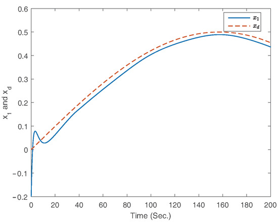
Figure 16.
The curves of the states and for Ref. [49].
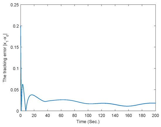
Figure 17.
The curve of the tracking error for Ref. [49].
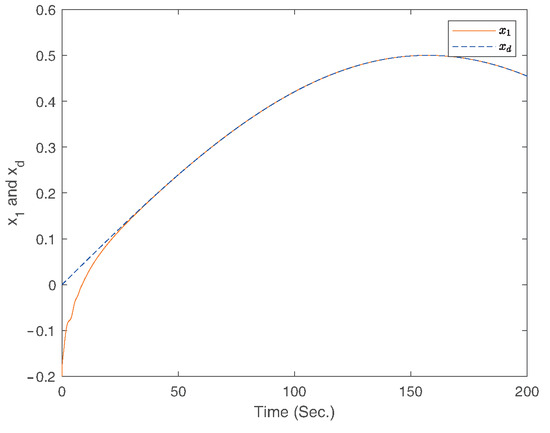
Figure 18.
The curves of the states and for fixed-time controller Equation (52).
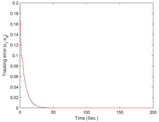
Figure 19.
The curve of the tracking error for fixed-time controller Equation (52).
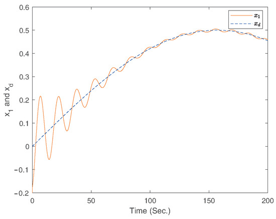
Figure 20.
The curves of the states and for finite-time controller Equation (74).
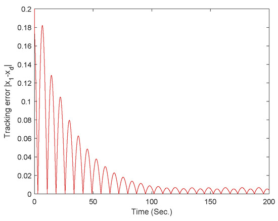
Figure 21.
The curve of the tracking error for finite-time controller Equation (74).
The simulation results show that good tracking performance can be achieved under the derived adaptive fixed-time control law in both of the two examples. Moreover, the derived adaptive fuzzy fixed-time control law can effectively reduce the impact of mismatched disturbances. It can also be seen that for different initial state conditions and external noises, the controller designed in this paper can effectively achieve tracking control of the system state, further demonstrating that the controller designed in this paper has good robustness. Thus, based on the above analysis, we can conclude that the fixed-time controller designed in this paper can achieve ideal performance in terms of convergence time, tracking performance, and robustness.
4. Conclusions
This article centered on tackling the fuzzy fixed-time control issue of uncertain nonlinear systems which encompass not only mismatched disturbances but also unknown nonlinear functions. Through the employment of the disturbance observers and adaptive approach, a multitude of problems arising from uncertain nonlinear functions and mismatched disturbances are properly addressed. By making use of the command-filtered technology and backstepping technique, a fixed-time fuzzy adaptive control protocol for uncertain nonlinear systems is formulated. The aforementioned control protocol design ensures the fixed-time stability of the controlled systems. Examples are presented to prove the efficiency of the derived control protocol. Therefore, the controller designed in this paper effectively solves the fixed-time tracking control problem of nonlinear systems. This controller is applicable to nonlinear systems with mismatched disturbances, such as robotic arms, carts, and so on. Future studies will aim to expand our suggested control approach to uncertain systems with unmeasurable states.
Author Contributions
Z.W.: conceptualization, methodology, software, writing, investigation. J.Z.: methodology, investigation, writing, conceptualization. L.X.: software, methodology, writing. L.S.: methodology, investigation, writing. All authors have read and agreed to the published version of the manuscript.
Funding
This research received no external funding.
Data Availability Statement
The original contributions presented in this study are included in the article.
Conflicts of Interest
The authors declare no conflicts of interest.
Abbreviations
| The mismatched disturbances | |
| The unknown nonlinear functions | |
| ,, , , p | The parameters of the fixed-time command filter |
| The output of fixed-time command filter | |
| The desired tracking signal | |
| The tracking error | |
| The compensated tracking error signal | |
| The parameter of the disturbance observer | |
| , , , , , | The parameters of the controller |
| , | The parameters of adaptive updating laws |
| The error compensating signal | |
| The virtual controllers |
References
- Zhu, D.; He, Y.; Li, F. Trajectory tracking of delta parallel robot via adaptive backstepping fractional-order non-singular sliding mode control. Mathematics 2024, 12, 2236. [Google Scholar] [CrossRef]
- Chalishajar, D.; Kasinathan, D.; Kasinathan, R.; Kasinathan, R. T-controllability of higher-order fractional stochastic delay system via integral contractor. J. Control Decis. 2024, 1–24. [Google Scholar] [CrossRef]
- Chalishajar, D.; Kasinathan, D.; Kasinathan, R.; Kasinathan, R. Exponentialstability, T-controllability and optimal controllability of higher-order fractional neutral stochastic differential equation via integral contractor. Chaos Solitons Fractals 2024, 186, 115278. [Google Scholar] [CrossRef]
- Asadi, D.; Bagherzadeh, S.A. Nonlinear adaptive sliding mode tracking control of an airplane with wing damage. Proc. Inst. Mech. Eng. Part J. Aerosp. Eng. 2018, 232, 1405–1420. [Google Scholar] [CrossRef]
- Asadi, D.; Atkins, E.M. Multi-objective weight optimization for trajectory planning of an airplane with structural damage. J. Intell. Robot. Syst. 2018, 91, 667–690. [Google Scholar] [CrossRef]
- Ahmed, A.S.; L-Nahhas, M.A.A.; Omar, O.A.; Chalishajar, D.N.; Ahmed, H.M. Controllability of impulsive nonlinear ψ-Hilfer fractional integro-differential equations. Results Control. Optim. 2024, 16, 100566. [Google Scholar] [CrossRef]
- Xie, X.; Wei, C.; Gu, Z.; Shi, K. Relaxed resilient fuzzy stabilization of discrete-time Takagi-Sugeno systems via a higher order time-variant balanced matrix method. IEEE Trans. Fuzzy Syst. 2022, 30, 5044–5050. [Google Scholar] [CrossRef]
- Jin, X.; Lü, S.; Yu, J. Adaptive NN-based consensus for a class of nonlinear multiagent systems with actuator faults and faulty networks. IEEE Trans. Neural Netw. Learn. Syst. 2021, 33, 3474–3486. [Google Scholar] [CrossRef] [PubMed]
- Chalishajar, D.; Chalishajar, H. Trajectory controllability of second order nonlinear integro-differential system: An analytical and a numerical estimation. Differ. Equ. Dyn. Syst. 2015, 23, 467–481. [Google Scholar] [CrossRef]
- Bagherzadeh, S.A.; Asadi, D. Detection of the ice assertion on aircraft using empirical mode decomposition enhanced by multi-objective optimization. Mech. Syst. Signal Process. 2017, 18, 9–24. [Google Scholar] [CrossRef]
- Asadi, D.; Ahmadi, K. Nonlinear robust adaptive control of an airplane with structural damage. Proc. Inst. Mech. Eng. Part J. Aerosp. Eng. 2020, 234, 2076–2088. [Google Scholar] [CrossRef]
- Asadi, D.; Farsadi, A.T. Active flutter control of thin walled wing-engine system using piezoelectric actuators. Aerosp. Sci. Technol. 2020, 102, 105853. [Google Scholar] [CrossRef]
- Kang, S.; Liu, P.X.; Wang, H. Command filter-based adaptive fuzzy decentralized control for large-scale nonlinear systems. Nonlinear Dyn. 2021, 105, 3239–3253. [Google Scholar] [CrossRef]
- Zhu, Z.; Liang, H.; Liu, Y.; Xue, H. Command filtered event-triggered adaptive control for MIMO stochastic multiple time-delay systems. Int. J. Robust Nonlinear Control 2022, 32, 715–736. [Google Scholar] [CrossRef]
- Wang, Y.; Xu, N.; Liu, Y.; Zhao, X. Adaptive fault-tolerant control for switched nonlinear systems based on command filter technique. Appl. Math. Comput. 2021, 392, 125725. [Google Scholar] [CrossRef]
- Yu, J.; Chen, B.; Yu, H.; Lin, C.; Zhao, L. Neural networks-based command filtering control of nonlinear systems with uncertain disturbance. Inf. Sci. 2018, 426, 50–60. [Google Scholar] [CrossRef]
- Liu, G.; Liang, H.; Pan, Y.; Ahn, C.K. Antagonistic interaction-based bipartite consensus control for heterogeneous networked systems. IEEE Trans. Syst. Man Cybern. Syst. 2022, 53, 71–81. [Google Scholar] [CrossRef]
- Xiao, Y.; de Ruiter, A.; Ye, D.; Sun, Z. Attitude coordination control for flexible spacecraft formation flying with guaranteed performance bounds. IEEE Trans. Aerosp. Electron. Syst. 2022, 59, 1534–1550. [Google Scholar]
- Yu, J.; Shi, P.; Zhao, L. Finite-time command filtered backstepping control for a class of nonlinear systems. Automatica 2018, 92, 173–180. [Google Scholar] [CrossRef]
- Capone, A.; Hirche, S. Backstepping for partially unknown nonlinear systems using Gaussian processes. IEEE Control Syst. Lett. 2019, 3, 416–421. [Google Scholar] [CrossRef]
- Fedele, G.; D’Alfonso, L. A kinematic model for swarm finite-time trajectory tracking. IEEE Trans. Cybern. 2018, 49, 3806–3815. [Google Scholar] [CrossRef] [PubMed]
- Wang, H.; Yu, W.; Ren, W.; Lu, J. Distributed adaptive finite-time consensus for second-order multiagent systems with mismatched disturbances under directed networks. IEEE Trans. Cybern. 2019, 51, 1347–1358. [Google Scholar] [CrossRef]
- Xiao, W.; Ren, H.; Zhou, Q.; Li, H.; Lu, R. Distributed finite-time containment control for nonlinear multiagent systems with mismatched disturbances. IEEE Trans. Cybern. 2022, 52, 6939–6948. [Google Scholar] [CrossRef]
- Wang, H.; Yu, W.; Ren, W.; Lu, J. Finite-time output consensus of higher-order multi-agent systems with mismatched disturbances and unknown state elements. IEEE Trans. Syst. Man Cybern. Syst. 2019, 66, 2571–2581. [Google Scholar]
- Wang, W.; Tong, S. Adaptive fuzzy containment control of nonlinear strict-feedback systems with full state constraints. IEEE Trans. Fuzzy Syst. 2019, 27, 2024–2038. [Google Scholar] [CrossRef]
- Shotorbani, A.M.; Mohammadi-Ivatloo, B.; Wang, L.; Marzband, M.; Sabahi, M. Application of finite-time control Lyapunov function in low-power PMSG wind energy conversion systems for sensorless MPPT. Int. Electr. Power Energy Syst. 2019, 106, 169–182. [Google Scholar] [CrossRef]
- Asadi, D. Actuator Fault detection, identification, and control of a multirotor air vehicle using residual generation and parameter estimation approaches. Int. J. Aeronaut. Space Sci. 2024, 25, 176–189. [Google Scholar] [CrossRef]
- Huo, X.; Karimi, H.R.; Zhao, X.; Wang, B.; Zong, G. Adaptive-critic design for decentralized event-triggered control of constrained nonlinear interconnected systems within an identifier-critic framework. IEEE Trans. Cybern. 2021, 52, 7478–7491. [Google Scholar] [CrossRef]
- Wang, N.; Gao, Y.; Yang, C.; Zhang, X. Reinforcement learning-based finite-time tracking control of an unknown unmanned surface vehicle with input constraints. Neurocomputing 2022, 484, 26–37. [Google Scholar] [CrossRef]
- Wang, L.; Liu, P.X.; Wang, H. Fast finite-time control for nonaffine stochastic nonlinear systems against multiple actuator constraints via output feedback. IEEE Trans. Cybern. 2022, 53, 3253–3262. [Google Scholar] [CrossRef] [PubMed]
- Sui, S.; Tong, S. Finite-time fuzzy adaptive ppc for nonstrict-feedback nonlinear mimo systems. IEEE Trans. Cybern. 2022, 53, 732–742. [Google Scholar] [CrossRef]
- Gao, M.; Ding, L.; Jin, X. Elm-based adaptive faster fixed-time control of robotic manipulator systems. IEEE Trans. Neural Netw. Learn. Syst. 2021, 34, 4646–4658. [Google Scholar] [CrossRef]
- Wu, Y.; Wang, Z. Fuzzy adaptive practical fixed-time consensus for second-order nonlinear multiagent systems under actuator faults. IEEE Trans. Cybern. 2020, 51, 1150–1162. [Google Scholar] [CrossRef]
- Ren, P.; Wang, F.; Zhu, R. Adaptive fixed-time fuzzy control of uncertain nonlinear quantized systems. Int. J. Fuzzy Syst. 2021, 23, 794–803. [Google Scholar] [CrossRef]
- Qin, H.; Yang, H.; Sun, Y.; Zhang, Y. Adaptive interval type-2 fuzzy fixed-time control for underwater walking robot with error constraints and actuator faults using prescribed performance terminal sliding-mode surfaces. Int. J. Fuzzy Syst. 2021, 23, 1137–1149. [Google Scholar] [CrossRef]
- Arabi, E.; Yucelen, T.; Singler, J.R. Finite-time distributed control with time transformation. Int. J. Robust Nonlinear Control 2021, 31, 107–130. [Google Scholar] [CrossRef]
- Yu, J.; Shi, P.; Liu, J.; Lin, C. Neuroadaptive finite-time control for nonlinear MIMO systems with input constraint. IEEE Trans. Cybern. 2020, 52, 6676–6683. [Google Scholar] [CrossRef] [PubMed]
- Li, K.; Hua, C.; You, X.; Guan, X. Finite-time observer-based leader-following consensus for nonlinear multiagent systems with input delays. IEEE Trans. Cybern. 2020, 51, 5850–5858. [Google Scholar] [CrossRef] [PubMed]
- Zhao, L.; Yu, J.; Lin, C.; Yu, H. Distributed adaptive fixed-time consensus tracking for second-order multi-agent systems using modified terminal sliding mode. Appl. Math. Comput. 2017, 312, 23–35. [Google Scholar] [CrossRef]
- Han, H.; Liu, H.; Li, J.; Qiao, J. Cooperative fuzzy-neural control for wastewater treatment process. IEEE Trans. Ind. 2020, 17, 5971–5981. [Google Scholar] [CrossRef]
- Chen, M.; Wang, H.; Liu, X. Adaptive fuzzy practical fixed-time tracking control of nonlinear systems. IEEE Trans. Fuzzy Syst. 2019, 29, 664–673. [Google Scholar] [CrossRef]
- Sun, H.; Hou, L.; Zong, G.; Yu, X. Fixed-time attitude tracking control for spacecraft with input quantization. IEEE Trans. Aerosp. Electron. Syst. 2018, 55, 124–134. [Google Scholar] [CrossRef]
- Qian, C.; Lin, W. A continuous feedback approach to global strong stabilization of nonlinear systems. IEEE Trans. Autom. 2001, 46, 1061–1079. [Google Scholar] [CrossRef]
- Deng, C.; Yang, G. Distributed adaptive fuzzy control for nonlinear multiagent systems under directed graphs. IEEE Trans. Fuzzy Syst. 2017, 26, 1356–1366. [Google Scholar]
- Yu, W.; Ren, W.; Zheng, W.X.; Chen, G.; Lü, J. Distributed control gains design for consensus in multi-agent systems with second-order nonlinear dynamics. Automatica 2013, 49, 2107–2115. [Google Scholar] [CrossRef]
- Liu, J.; Zhang, Y.; Yu, Y.; Sun, C. Fixed-time event-triggered consensus for nonlinear multiagent systems without continuous communications. IEEE Trans. Syst. Man Cybern. Syst. 2018, 49, 2221–2229. [Google Scholar] [CrossRef]
- Shi, X.; Zhou, Z.; Zhou, D.; Li, R.; Chen, X. Observer-based event-triggered fixed-time control for nonlinear system with full-state constraints and input saturation. Int. J. Control 2022, 95, 432–446. [Google Scholar] [CrossRef]
- Xu, H.; Yu, D.; Sui, S.; Zhao, Y.; Chen, C.P.; Wang, Z. Nonsingular practical fixed-time adaptive output feedback control of MIMO nonlinear systems. IEEE Trans. Neural Netw. Learn. Syst. 2022, 34, 7222–7234. [Google Scholar] [CrossRef]
- Liu, R.; Liu, M.; Shi, Y.; Qu, J. Adaptive fixed-time fuzzy control for uncertain nonlinear systems with asymmetric time-varying full-state constraints. Int. J. Fuzzy Syst. 2023, 25, 1597–1611. [Google Scholar] [CrossRef]
Disclaimer/Publisher’s Note: The statements, opinions and data contained in all publications are solely those of the individual author(s) and contributor(s) and not of MDPI and/or the editor(s). MDPI and/or the editor(s) disclaim responsibility for any injury to people or property resulting from any ideas, methods, instructions or products referred to in the content. |
© 2024 by the authors. Licensee MDPI, Basel, Switzerland. This article is an open access article distributed under the terms and conditions of the Creative Commons Attribution (CC BY) license (https://creativecommons.org/licenses/by/4.0/).