Article

Mixed-Mode Fracture Analysis of a Patterned Si Electrode during Lithiation/Delithiation

1
Missile Research Institute, Agency for Defense Development, Yuseong Post Office P.O. Box 35ho, Yuseong-gu, Daejeon 34186, Republic of Korea
2
Department of Mechanical Design Engineering, Kumoh National Institute of Technology, Gumi 39177, Republic of Korea
*
Authors to whom correspondence should be addressed.
Mathematics 2024, 12(2), 188; https://doi.org/10.3390/math12020188
Submission received: 12 December 2023 / Revised: 31 December 2023 / Accepted: 4 January 2024 / Published: 6 January 2024
(This article belongs to the Section Engineering Mathematics)

Abstract

:
We investigate the mechanical degradation of patterned Si based on large deformation theory and mixed-mode failure. Mode I debonding at the center of Si is found to suddenly increase and lead to crack initiation during the early stages of lithiation. The generated crack propagates to the surface and hinders Li diffusion, thus increasing the inhomogeneity of Li within Si. During delithiation, very little Mode I and Mode II debonding occur near the center of the patterned Si; however, both Mode I and Mode II debonding develop considerably at the surface. In addition, the effects of the charge/discharge rate are considered. A very low state of charge induces crack initiation at the center of Si, regardless of the charge rate. The charge/discharge rate is correlated with the total crack length, which is directly proportional to the charge rate. Based on our simulation results, we propose a new shape of the patterned Si with a hole in order to enhance mechanical stability. The hole prevents crack growth by releasing the internal stress, and Mode I debonding at the center of the patterned Si becomes significantly lower, with much slower increases during lithiation.

1. Introduction

The capacity to fade during the charge–discharge cycle is a critical challenge to the advanced development of Li-ion batteries [1]. Electrode damage, such as cracking, is one of the primary causes of battery degradation. The stresses resulting from the electrode’s volumetric change induce cracking within the electrode during lithiation and delithiation [2]. For example, Si anodes have shown severe cracking associated with the large volume change induced by Li insertion/extraction cycles [3]. The detrimental impact of high charge rates on silicon anodes is increasingly evident in recent experimental studies, particularly as larger volume expansion of silicon consistently exhibits heightened levels of damage [4,5,6,7,8,9]. To prevent this electrode damage and enhance the cyclic performance of Li-ion batteries, nanosized Si materials have been systematically investigated, including nanoparticles, nanowires, and thin-film structures [10,11,12,13,14,15,16]. However, nanomaterial fabrication is expensive, and the high surface-to-volume ratio in nanostructures inevitably increases the unexpected SEI layer [17]. Haftbaradaran et al. recently proposed a method of deducing the critical size for interfacial delamination of patterned thin-film electrodes [18]. Lu et al. also investigated the state of charge and the time to the onset of interfacial delamination and suggested a critical Si size to prevent delamination [19]. These studies mainly focused on the delamination growth between Si and the substrate in Si thin films.
In this study, we extend previous works on the chemo-mechanical behavior of Si. We propose a continuum model to elucidate the diffusion-induced fracture mechanism in patterned Si. Our investigation into the silicon fracture phenomena was inspired by the experimental outcomes of Sternad et al. [9]. During lithiation/delithiation cycles, internal cracking is unavoidable and necessarily affects the Li diffusion [20]. Li typically diffuses around the crack, as shown in Figure 1; consequently, the Li concentration inhomogeneity in Si increases with crack density.
The objective of this study is to investigate the dynamic internal cracking behavior of patterned Si based on large deformation theory and a cohesive zone model. For the internal crack propagation under diffusion-induced stress, we consider mixed-mode cracking. Mode I debonding suddenly increases at the center of Si according to the Li insertion, whereas in the early stage of delithiation, both Mode I and Mode II debonding develop considerably at the LixSi surface.

2. Methodology

2.1. Li Diffusion in Patterned Si

We consider a chemo-mechanical potential μ * that consists of the stress-independent chemical potential (i.e., μ = ψ ( c , T ) / c ) and the stress-dependent chemical potential for the diffusion of Li. The stress-independent chemical potential includes the effects of system entropy and concentration-dependent mixing enthalpy. The stress-dependent mechanical work is associated with the elastic energy during the insertion (removal) of Li into (from) the Si host under hydrostatic stress, which can generate an additional driving force for Li diffusion [21]. Hence, μ * is defined as Equation (1) [22].
μ * = μ 0 L i + R T ln c ~ 1 c ~ Ω σ h + 2 A 0 2 B 0 c ~ 3 A 0 B 0 c ~ 2 + B 0
Here, μ 0 L i ,   R ,   T ,   c ~ , Ω ,   σ h ,   A 0 , and B 0 are the standard chemical potential of Li, the universal gas constant, the absolute temperature, the normalized Li concentration in Si (i.e., c ~ = c / c m a x ), the partial molar volume of Li, the hydrostatic stress ( σ h = σ 11 + σ 22 + σ 33 / 3 ), and two empirical parameters, respectively. For a detailed derivation of the above equation, we refer readers to our previous paper [22].
With the chemo-mechanical potential thus defined, the Li diffusion flux, j , on the surface of the patterned Si is given by Equation (2).
j = M c μ *
Here, M and c represent the mobility of the diffusing Li component and the molar concentration of Li (mole/m3), respectively.
Based on Equation (1), Equation (2), and the law of conservation of mass, we can derive Equation (3).
c t = · j = · D c m a x c m a x c c Ω c σ h R T + 2 A 0 B 0 R T c c m a x + 6 ( A 0 B 0 ) R T c c m a x 2 c
The boundary conditions are set to an initial Li concentration of 0 (i.e., c = 0 for t = 0 ), and the Li flux is maintained in a steady state. The electrochemical reaction at the Si surface is related to the applied discharge/charge current density given by Faraday’s law, j = i / F , where i is the current density and F is the Faraday constant. The parameters used for Li diffusion in the patterned Si electrode are presented in Table 1.

2.2. Large Deformation Theory in Si

2.2.1. Kinematics of Multiplicative Plasticity in Patterned Si

During lithiation of the patterned Si, LixSi is subjected to elastoplastic deformation, mainly due to the large chemical strain [8]. We assume that the lithiation-induced large deformation of the patterned Si is governed by an elastic and perfectly plastic constitutive relationship. Thus, any material point in LixSi can be represented by a continuous displacement field u .
u X , t = x X
Here, u , x , and X are the displacement field, the material point at time t in the spatial configuration, and the initial position at t = 0 in the reference configuration, respectively. The deformation gradient is determined as:
F = ( X + u ) X = I + u X
In the framework of large deformation theory, the multiplicative decomposition of the deformation gradient is defined as:
F = F e F * ,   F * = F p F c
where F c represents the compositional deformation gradient that describes the volumetric swelling due to an insertion of lithium in Si with a concentration of c . Hence, F c can be described as:
F c = J c 1 / 3 I ,   J c = 1 + η c
where J c , I , η , and c are the compositional Jacobian, an identity tensor, the coefficient of compositional expansion, and the molar concentration of lithium, respectively. F p and F e are the plastic and elastic components, respectively, of the total deformation gradient in Equation (6). Thus, this framework maps the reference configuration to the intermediate configuration by considering an inelastic deformation F * .
The total Jacobian of this sequence of transformations, J = J e J p J c = d e t ( F ) , is composed of an elastic component, j e = det F e > 0 ; a plastic component, j p = det F p > 0 ; and a stress-free expansion component, j c = det F c > 0 . In this study, we assume that the plastic flow is incompressible; hence, the total Jacobian becomes j = j e j c .
The velocity gradient in the spatial configuration can be obtained as:
l = x v = F ˙ F 1 = F ˙ e F e 1 + F e F ˙ p F p 1 F e 1 + F e F ˙ c F c 1 F e 1 = l e + F e ( L p + L c ) F e 1
with l e = F ˙ e F e 1 , L p = F ˙ p F p 1 , and L c = F ˙ c F c 1 .
Here, L p is a plastic velocity gradient defined in an intermediate stress-free configuration (incompatible). The symmetric part of L p is the plastic rate of deformation, D p , and the skew-symmetric part of L p is the plastic spin, W p , as shown below.
D p = 1 2 L p + L p T ,   W p = 1 2 L p L p T
It is widely assumed that the plastic flow is irrotational: W p = 0 [18]; thus, L p = D p .

2.2.2. Elastic and Flow Plasticity in Patterned Si

The elastic behavior of the patterned Si is measured using an elastic right Cauchy-Green deformation tensor:
C e = F e T · F e
The symmetrized Mandel stress tensor, M e , is defined for finite plasticity:
M e = 1 2 C e · S + S C e
where S is the second Piola–Kirchhoff stress.
The flow rule in terms of the plastic component of the velocity gradient is defined as:
L p = D p = λ ˙ f M e
where λ ˙ is a plastic strain rate constant and f is a yield function. The yield function for perfect plasticity is represented as:
f M e = 3 2 M e d : M e d σ Y = 0
where M e d is the deviatoric component of M e and σ Y is the yield strength.
According to the Kuhn–Tucker condition, loading–unloading can be expressed as:
λ ˙ 0 ,   f 0 ,   λ ˙ f = 0
which appended the consistency condition λ ˙ f ˙ = 0 when f = 0.

2.2.3. Mechanical Equilibrium

The time required for the mechanical equilibrium is considered as the quasi-static state at any time, i.e.:
X · P X = 0 ,   x · σ X = 0 ,   P = J F 1 · σ
where P is the first Piola–Kirchhoff stress tensor and σ is the Cauchy stress tensor. In the spatial configuration, the traction-free surface required for the mechanical equilibrium is given as:
n · σ = 0   on   S
where n and S are the outward normal of the outer surface of the Si and the outer surface of the Si, respectively.

2.3. Mixed-Mode Crack Growth in Patterned Si

Internal crack growth in the patterned Si is likely to occur under the condition of simultaneous mixed-mode debonding, in which the damage is initiated even before any of the tractions required for a single mode reach their respective threshold values. Sternad et al. presented experimental observations, stating “The lateral dilation occurs during Li uptake” [9]. Based on these experimental findings, patterned silicon allows for the non-uniform insertion and desertion of lithium from both sides along the height of the patterned silicon. Therefore, we have concluded that the mixed-mode model, encompassing the Mode II fracturing phenomenon, is appropriate.

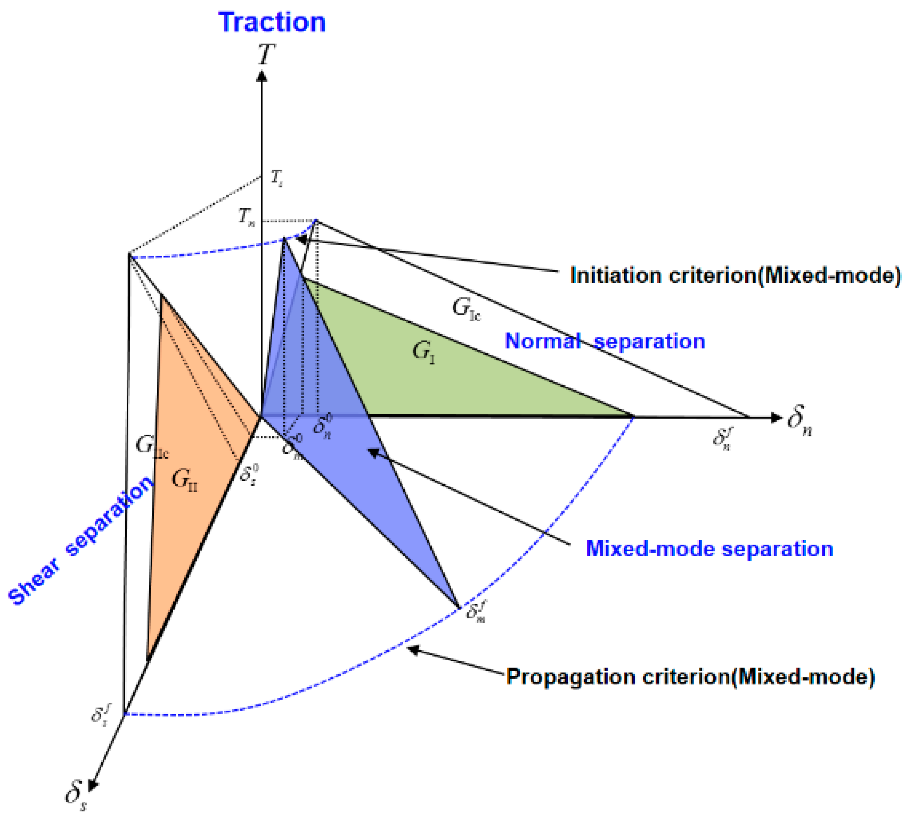
2.3.1. Mixed-Mode Initiation Criterion

The interaction of the traction components associated with crack initiation can be determined by different criteria. Crack initiation under the mixed-mode traction condition is defined in Figure 2.
In mixed-mode separation, the total mixed-mode relative displacement δ m is defined as:
δ m = δ n 2 + δ s 2
where δ n and δ s are the normal relative displacement and the shear relative displacement, respectively. The operation   is the Macaulay bracket, defined as:
x = 0 ,   x < 0 x ,   x 0
We adopt the same penalty stiffness K for Modes I and II as shown below:
T i = K δ i , i = n , s
The crack initiation can be predicted using the quadratic debonding criterion [25,26]. When a quadratic interaction function involving the nominal stress ratio becomes one, the damage is initiated, as defined in Equation (20).
T n N + T s S = 1
Here, N and S are the maximum allowable tractions for Modes I and II, respectively. The relative displacement of each mode at crack initiation becomes:
δ n 0 = T n K ,   δ s 0 = T s K
The mode mix ratio β is defined as:
β = δ s δ n
Based on the above equations, mixed-mode damage initiation is determined by:
δ m 0 = δ n 0 δ s 0 1 + β 2 δ s 0 2 + β δ n 0 2 ,   δ n > 0 δ s 0 ,   δ n 0
Single modes are particular cases of this proposed formulation, in which β = 0   for Mode I and β =   for Mode II.

2.3.2. Mixed-Mode Propagation Criterion

A mixed-mode crack propagation criterion that uses the energy-based Benzeggagh and Kenane (B-K) fracture criterion appears to deliver an adequate description of fracture in patterned Si [27]. The critical energy release rate, G c , in the B-K criterion is evaluated based on the cohesive energy of Mode I and Mode II:
G c = G I c + ( G I I c G I c ) G I I G I + G I I η
where the parameter η that determines the mixed-mode ratio is normally between 1 and 2. In the absence of detailed information on appropriate η values, we assume η = 1 in this study.
The cohesive energy absorbed by each mode in mixed-mode loading can be defined as:
G I c = K δ n m 0 δ n m f 2   and   G I I c = K δ s m 0 δ s m f 2
where δ n m 0 and δ s m 0 are the normal and shear relative displacements, respectively, corresponding to the crack initiation under mixed-mode loading, and δ n m f and δ s m f are the normal and shear relative displacements, respectively, corresponding to complete separation under mixed-mode loading, as shown in Figure 2.
In Equations (17) and (22)–(25), the total relative displacement corresponding to complete separation can be obtained as:
δ m f = 2 K δ m 0 G I c + ( G I I c G I c ) β 2 β 2 + 1 η ,   δ n > 0 δ s f ,   δ n 0

2.3.3. Constitutive Equation for Mixed-Mode Loading

Only the maximum mixed-mode relative displacement δ m m a x = m a x δ m m a x , δ m at each point on the cohesive zone interface is used to characterize the damage. Therefore, the damage evolution function can be defined as:
d = δ m f δ m m a x δ m 0 δ m m a x δ m f δ m 0
The irreversible bilinear softening constitutive behavior of the normal component under mixed-mode loading is defined as:
K I = K I I   0 < δ n K   δ n < 0
For the shear component:
K I I = K   δ m m a x δ m 0 1 d K   δ m 0 < δ m m a x δ m f 0   δ m f < δ m m a x
The parameters used for mixed-mode debonding in patterned Si are presented in Table 2.

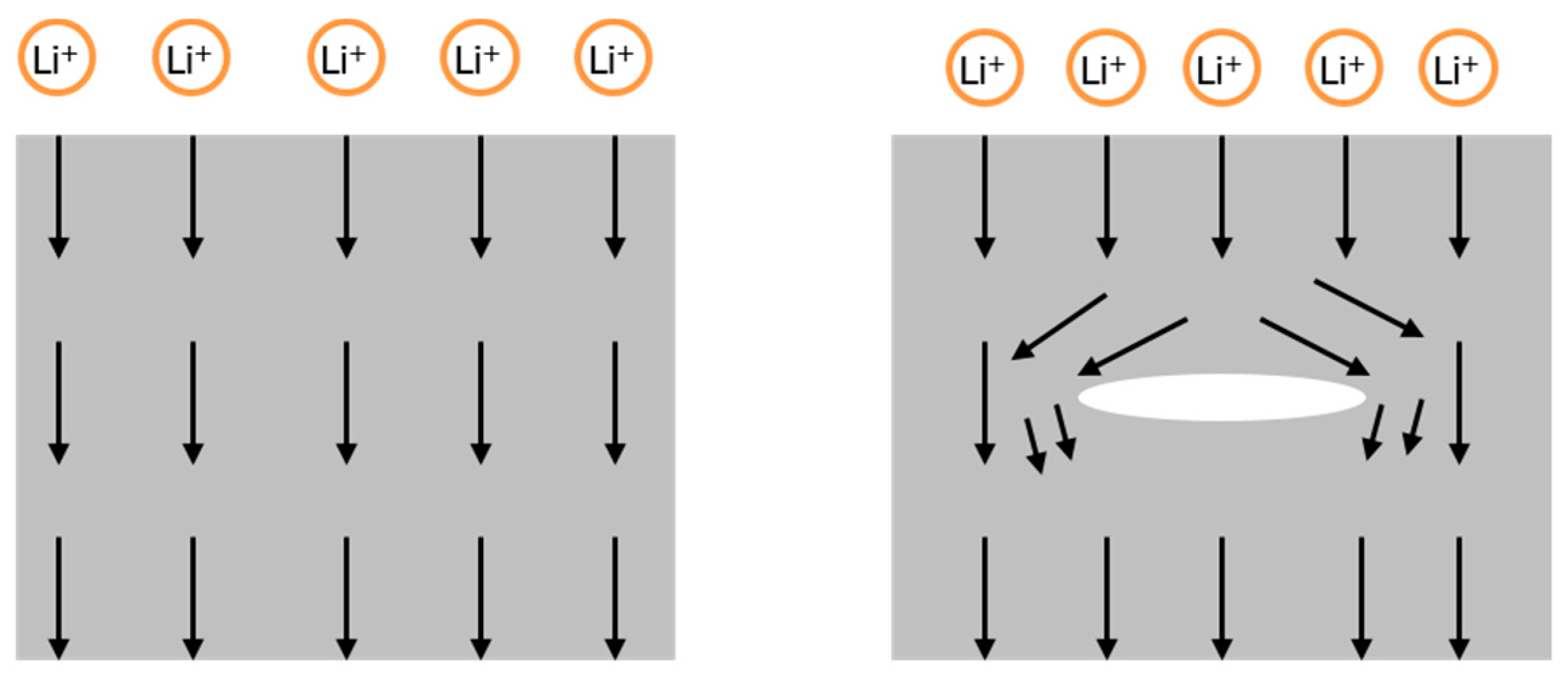
2.4. Li Diffusion and the Effect of Cracking on Li Diffusion

When there is internal damage in the patterned Si, the diffusion of Li is disturbed, and Li will be diverted around the crack. Therefore, the electrode’s internal damage reduces the effective diffusivity of Li and causes Li inhomogeneity in the patterned Si.
The diffusion of Li in Si due to the influence of cracks is assumed as follows.
j = M c μ * ,   δ m m a x δ m f   0 ,   δ m m a x > δ m f
When the total relative displacement, δ m m a x , exceeds that required for complete separation, δ m f , under mixed-mode loading, Li diffusion is severed, and the Li flux becomes zero.
The governing equation has been resolved using COMSOL Multiphysics, employing both the General PDE module and the Structural Mechanics module.

3. Results and Discussion

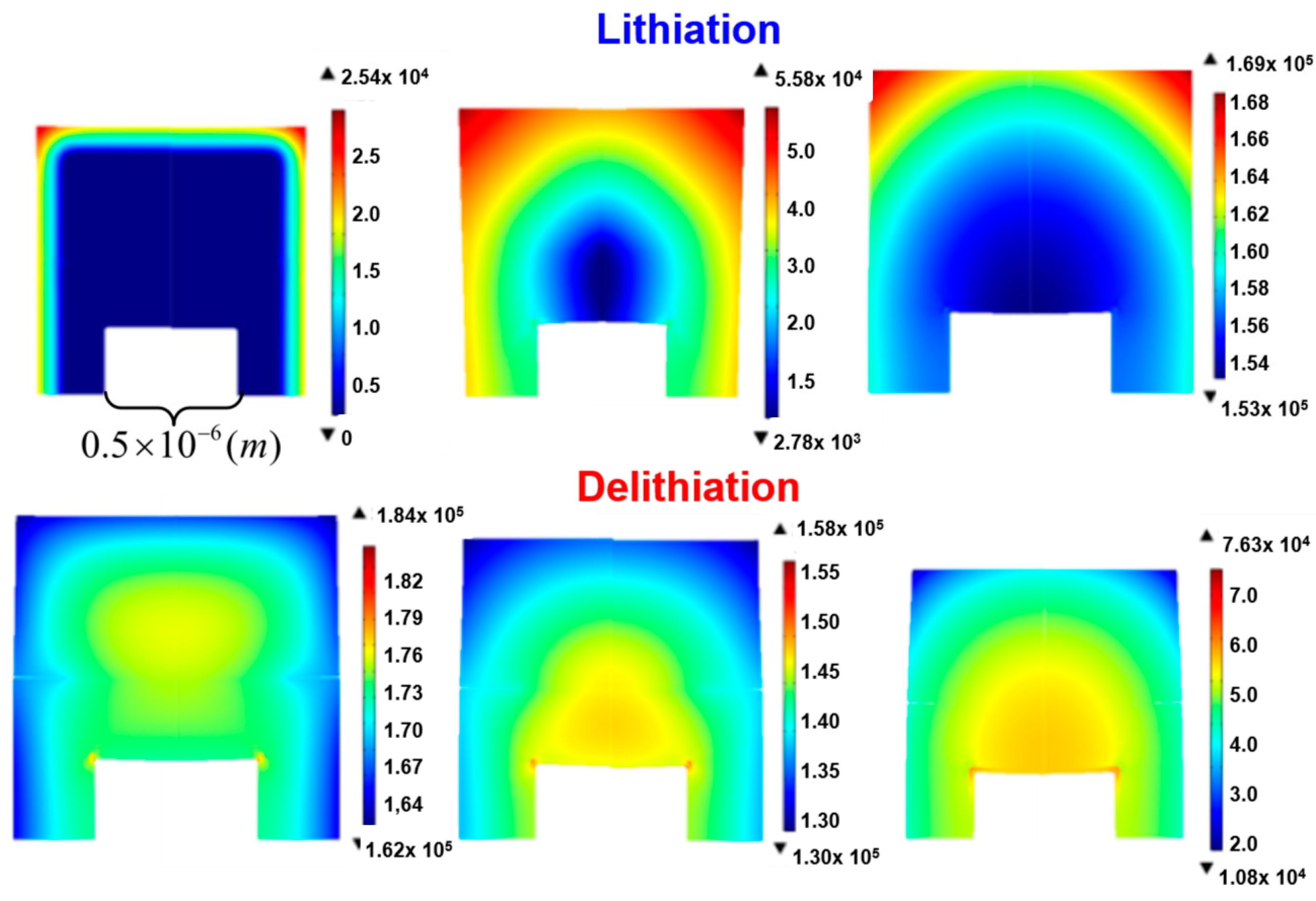
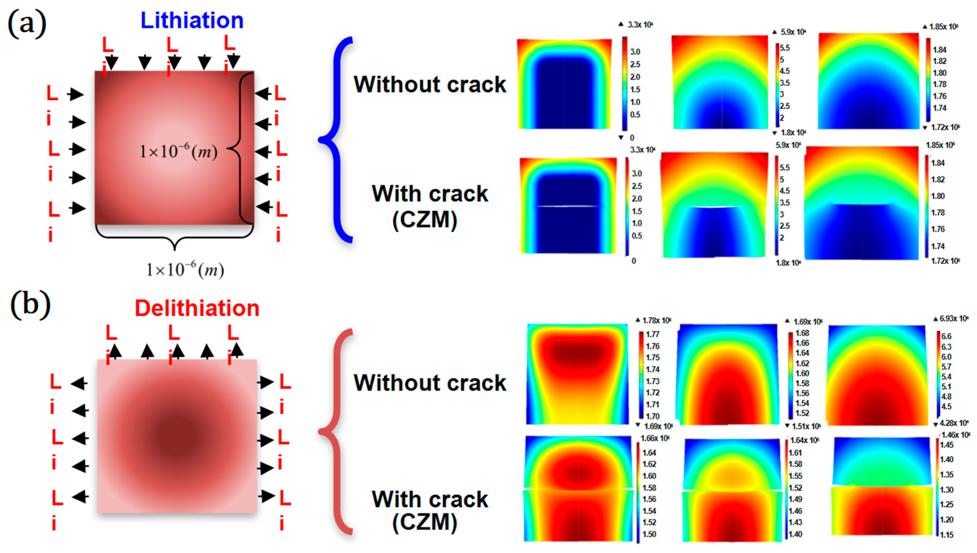
3.1. Lithium Distribution with and without an Internal Crack

Figure 3 shows Li distribution in patterned Si with and without an internal crack during lithiation (a) and delithiation (b).
An electrochemical reaction occurs on the exposed side (top, left, right) of the patterned Si, and thus, Li evenly diffuses into the Si. In the absence of cracks inside the electrode, the diffusion of lithium naturally tends to be smooth. In the cohesive zone model, a crack is observed inside the patterned Si in the early lithiation stage, and the Li responds by moving along a tortuous pathway around the crack. The inhomogeneity of the Li distribution becomes increasingly pronounced, and Si immediately below the internal crack is prevented from reacting with Li; therefore, less Li is absorbed by the patterned Si. During delithiation, the internal crack growth also impedes the diffusion of Li exiting from the Si, stopping the electrochemical reaction before a large amount of Li is extracted. This phenomenon limits the electrical capacity of Li-ion batteries.

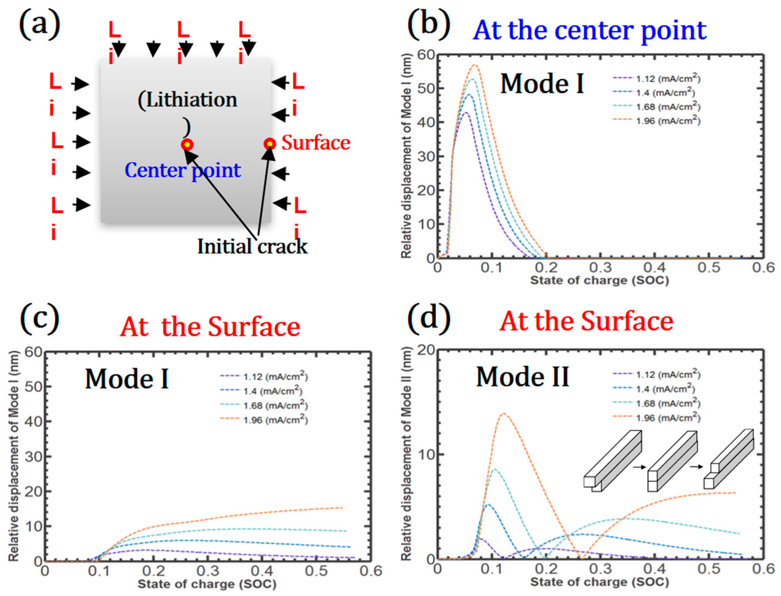
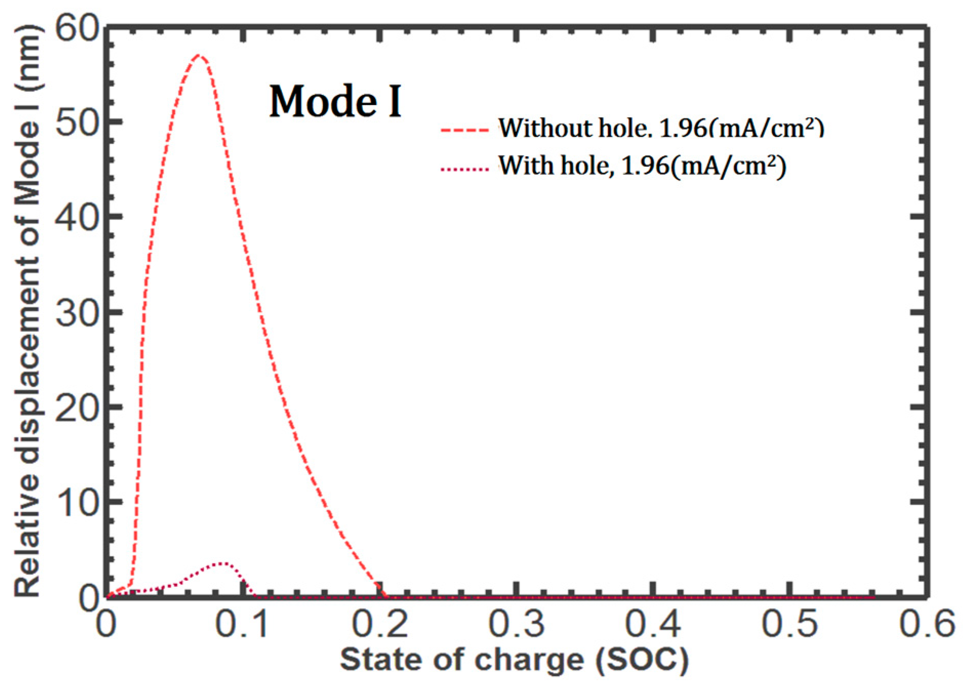
3.2. Debonding during Lithiation at Different Charge Rates

We assume that the initial nanoscale crack extends between the center and the surface of the patterned Si, resulting in the creation of a new crack surface, as shown in Figure 4a. Mode I and Mode II debonding behavior at the center and surface are investigated during lithiation. During the early stages of lithiation, Mode I debonding suddenly increases at the center point because of the deformation of LixSi, which is the primary reason for the crack growth in the central region of the Si. This failure is sufficiently large to interfere with Li diffusion within the Si, and irreversibly large cracks permanently disconnect the Li diffusion pathway. However, the relative displacement of Mode I decreases with further lithiation because the chemical strain near the crack gradually increases. At the surface points, Mode I debonding does not occur during early lithiation. However, with increased internal strains, such as elastic, plastic, and chemical strains, the push-out effect develops on the surface, inducing Mode I debonding that increases with lithiation, as shown in Figure 4c. As the charge rate increases, the relative displacements in Mode I at both points increase, and the rate dependency of the debonding at the center point is more prominent than the surface.
Mode II debonding is not observed at the center point because of the symmetric Li flux; however, Mode II debonding on the surface increases, decreases, and increases as lithiation progresses. The larger lateral expansion of the upper part of LixSi resulting from the greater Li absorption initiates Mode II debonding. However, as the Li circumvents the internal crack, the lateral expansion of the lower part of the crack interface also increases, and the lateral expansions along the crack interface become temporarily compatible. With further lithiation, the difference between the lateral expansions of the two parts increases reversely. The relative displacement of Mode II also increases as the charge rate increases. In summary, during lithiation, Mode I debonding is the dominant crack formation mechanism near the center; however, the relative displacement of Mode I is comparable to Mode II on the surface of the patterned Si.

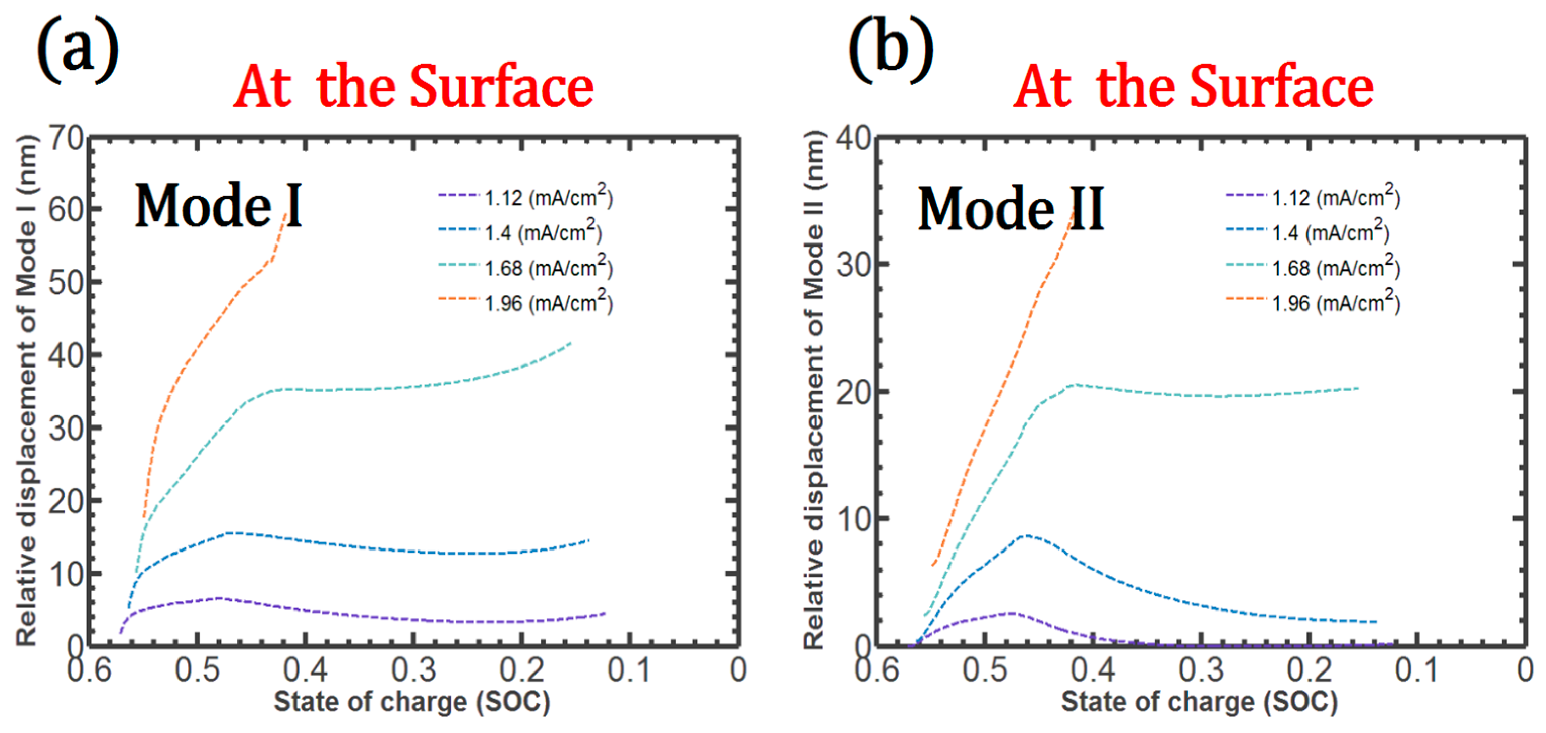
3.3. Debonding during Delithiation at Different Charge Rates

During delithiation, very little Mode I or Mode II debonding occurs near the center of the patterned Si. However, in the early stage of delithiation, both Mode I and Mode II debonding develop considerably at the surface, as shown in Figure 5.
In particular, when the charge rate is more than 1.68 (mA/cm2), Mode I and Mode II debonding increase markedly, resulting in complete debonding near the surface. In addition, the discontinuities in the Li concentration that are associated with the crack accelerate crack growth.

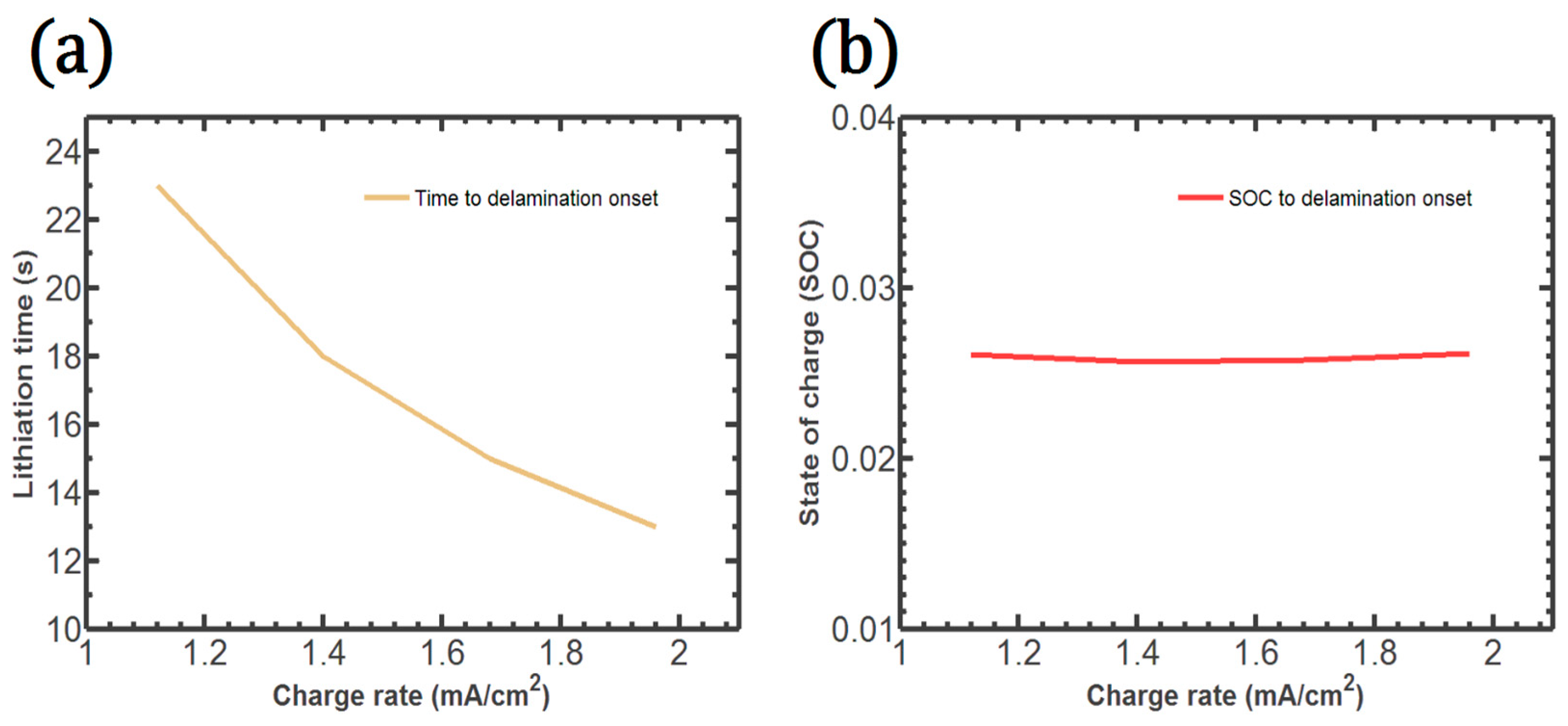
3.4. Time and State of Charge (SOC) to the Crack Onset

The time to the crack onset at the center point with respect to the charge rate is illustrated in Figure 6a. The time to crack onset decreases monotonically with increasing charge rates. In contrast, the SOC to crack onset at the center point remains almost constant regardless of the charge rate, as shown in Figure 6b. Therefore, the SOC has a dominant influence on crack initiation. In addition, a very small amount of Li plays a critical role in the crack onset.

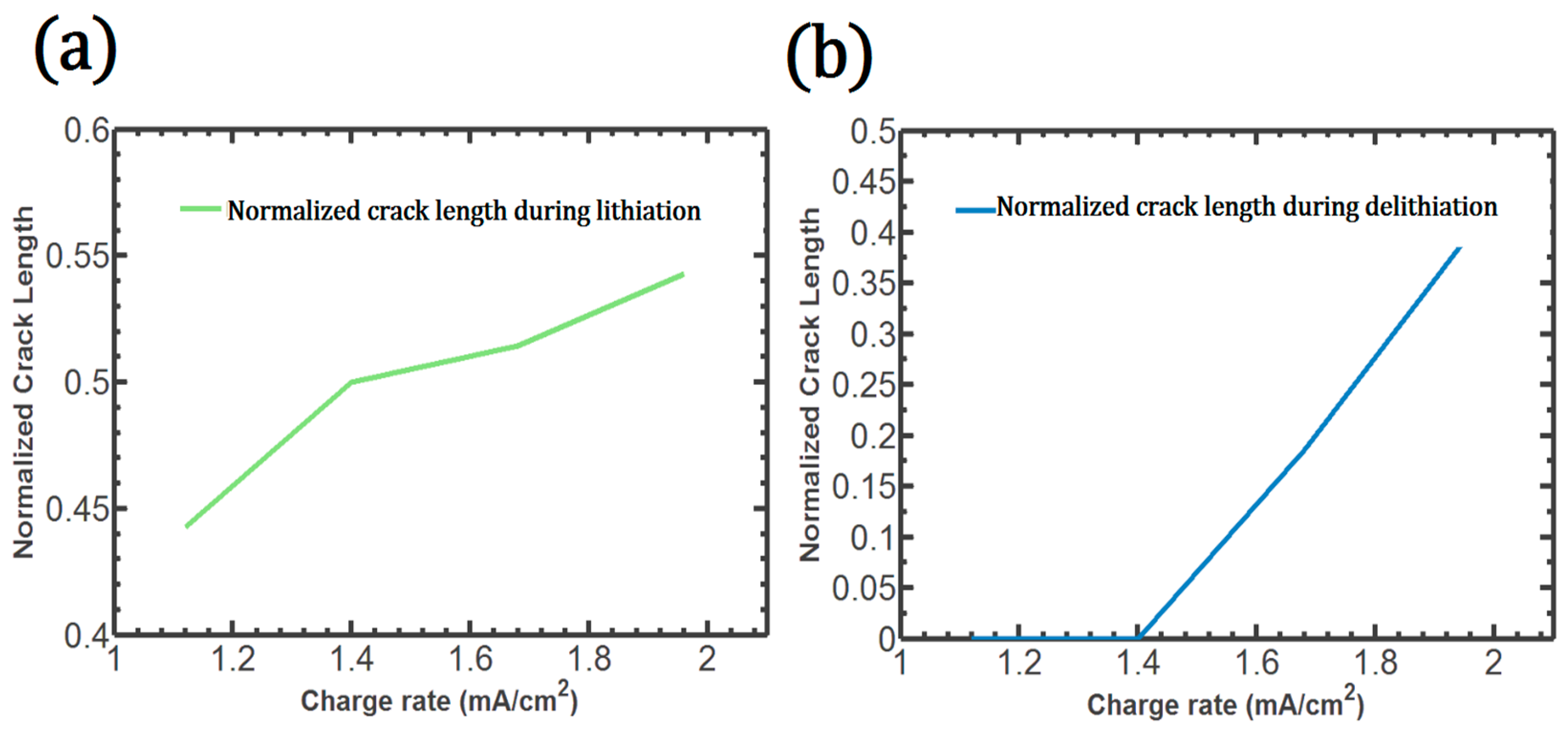
3.5. Crack Length at Different Charge Rates

During lithiation, the crack is initiated at the center of the patterned Si, where Mode I debonding is typically the dominant failure mode.
This crack propagates rapidly to the surface. The total crack length during lithiation is directly proportional to the charge rate, as described in Figure 7a. The crack occurs at all the charge rates investigated in this study. During delithiation, the complete debonding on the surface is found only with high charge rates, such as 1.68 (mA/cm2) and 1.96 (mA/cm2), as shown in Figure 7b. Therefore, the crack growth acceleration induced by the Li concentration discontinuity could be reduced by controlling the charge rate or Si morphology. At the highest charge rate, 1.96 (mA/cm2), the patterned Si shows complete debonding along the cohesive element, which is generally regarded as a huge capacity loss factor resulting from the active particle loss.

3.6. Breakthrough in Patterned Si

Based on our simulation results, we propose a new shape of the patterned Si, as shown in Figure 8. The proposed shape can overcome the aforementioned limitations and improve structural stability. The cohesive zone model in Figure 3 shows that a large amount of Li is trapped inside the patterned Si after one charge–discharge cycle, and the model also shows that high charge rates cause large cracks within the Si. In this case, an inevitable capacity fade would be expected. However, the proposed hollow-core cube shape shows enhanced mechanical and electrochemical performance. The hollow shape relaxes the internal stress and prevents crack generation during lithiation and delithiation.
Gallagher et al. presented the fabrication of hollow silica cubes. These cubes were synthesized by depositing a thin silica shell onto micrometer-sized hematite cubes. Subsequently, the core hematite was chemically removed. It is anticipated that a similar approach, utilizing chemical etching techniques, could be employed to create holes in patterned silicon [30].
Figure 9 shows that Mode I debonding is reduced by more than ten times when the empty space is established in the patterned Si. Mode I debonding at the center point is significantly lower and does not rise steeply during lithiation. Thus, the proposed structure is shown to provide a favorable solution to the problems associated with diffusion-induced stress, preventing crack growth by releasing internal stress through the established hole.

4. Conclusions

Based on large deformation theory and a mixed-mode cohesive zone model, we investigated the dynamic cracking behavior of patterned Si during lithiation and delithiation. Mode I debonding at the center of Si leads to crack initiation during lithiation, and this failure is sufficiently large and can interfere with Li diffusion within the Si. During delithiation; very little Mode I or Mode II debonding occurs near the center of the patterned Si. However, in the early stage of delithiation, both Mode I and Mode II debonding develop considerably at the surface. As the charge rate increases, the relative displacement in Mode I at both points increases, and the rate dependency of the debonding in the center point is more prominent than the surface. In addition, discontinuities in the Li concentration are shown to be associated with accelerated crack growth. Furthermore, the SOC is shown to have a dominant influence on crack initiation; a very low SOC causes crack initiation at the center point of Si, regardless of the charge rate. However, the charge/discharge rate influences the total crack length and is directly proportional to the charge rate. Based on our simulation results, we propose a new shape of the patterned Si to enhance mechanical stability.

Author Contributions

Conceptualization, Y.G. and J.-W.H.; methodology, Y.G. and J.-W.H., software, Y.G. and J.-W.H.; validation, Y.G. and J.-W.H.; formal analysis, Y.G. and J.-W.H.; investigation, Y.G. and J.-W.H.; resources, Y.G. and J.-W.H.; data curation, Y.G. and J.-W.H.; writing—original draft preparation, Y.G. and J.-W.H.; writing—review and editing, Y.G. and J.-W.H.; visualization, Y.G. and J.-W.H.; supervision, Y.G. and J.-W.H.; project administration, Y.G. and J.-W.H.; funding acquisition, Y.G. and J.-W.H. All authors have read and agreed to the published version of the manuscript.

Funding

This work was supported by the National Research Foundation of Korea (NRF) grant funded by the Korean government (MSIT) (NRF-No. 2022R1C1C1012599).

Data Availability Statement

Data are contained within the article.

Conflicts of Interest

The authors declare no conflicts of interest.

References

  1. Kasavajjula, U.; Wang, C.S.; Appleby, A.J. Nano- and bulk-silicon-based insertion anodes for lithium-ion secondary cells. J. Power Sources 2007, 163, 1003. [Google Scholar] [CrossRef]
  2. Zhang, W.J. A review of the electrochemical performance of alloy anodes for lithium-ion batteries. J. Power Sources 2011, 196, 13. [Google Scholar] [CrossRef]
  3. Wang, Y.H.; He, Y.; Xiao, R.J.; Li, H.; Aifantis, K.E.; Huang, X.J. Investigation of crack patterns and cyclic performance of Ti-Si nanocomposite thin film anodes for lithium ion batteries. J. Power Sources 2012, 202, 236. [Google Scholar] [CrossRef]
  4. Teki, R.; Datta, M.K.; Krishnan, R.; Parker, T.C.; Lu, T.M.; Kumta, P.N.; Koratkar, N. Nanostructured Silicon Anodes for Lithium Ion Rechargeable Batteries. Small 2009, 5, 2236. [Google Scholar] [CrossRef] [PubMed]
  5. Bhandakkar, T.K.; Gao, H.J. Cohesive modeling of crack nucleation under diffusion induced stresses in a thin strip: Implications on the critical size for flaw tolerant battery electrodes. Int. J. Solids Struct. 2010, 47, 1424. [Google Scholar] [CrossRef]
  6. Ryu, I.; Choi, J.W.; Cui, Y.; Nix, W.D. Size-dependent fracture of Si nanowire battery anodes. J. Mech. Phys. Solids 2011, 59, 1717. [Google Scholar] [CrossRef]
  7. Liu, X.H.; Zhong, L.; Huang, S.; Mao, S.X.; Zhu, T.; Huang, J.Y. Size-Dependent Fracture of Silicon Nanoparticles During Lithiation. Acs Nano 2012, 6, 1522. [Google Scholar] [CrossRef]
  8. Gwak, Y.; Jin, Y.; Cho, M. Cohesive zone model for crack propagation in crystalline silicon nanowires. J. Mech. Sci. Technol. 2018, 32, 3755. [Google Scholar] [CrossRef]
  9. Sternad, M.; Forster, M.; Wilkening, M. The microstructure matters: Breaking down the barriers with single crystalline silicon as negative electrode in Li-ion batteries. Sci. Rep. 2016, 6, 31712. [Google Scholar] [CrossRef]
  10. Hieu, N.T.; Suk, J.; Kim, D.W.; Chung, O.H.; Park, J.S.; Kang, Y. Silicon nanoparticle and carbon nanotube loaded carbon nanofibers for use in lithium-ion battery anodes. Synth. Met. 2014, 198, 36. [Google Scholar] [CrossRef]
  11. Chan, C.K.; Peng, H.L.; Liu, G.; McIlwrath, K.; Zhang, X.F.; Huggins, R.A.; Cui, Y. High-performance lithium battery anodes using silicon nanowires. Nat. Nanotechnol. 2008, 3, 31. [Google Scholar] [CrossRef] [PubMed]
  12. Liu, X.H.; Zheng, H.; Zhong, L.; Huan, S.; Karki, K.; Zhang, L.Q.; Liu, Y.; Kushima, A.; Liang, W.T.; Wang, J.W.; et al. Anisotropic Swelling and Fracture of Silicon Nanowires during Lithiation. Nano Lett. 2011, 11, 3312. [Google Scholar] [CrossRef] [PubMed]
  13. Moon, T.; Kim, C.; Park, B. Electrochemical performance of amorphous-silicon thin films for lithium rechargeable batteries. J. Power Sources 2006, 155, 391. [Google Scholar] [CrossRef]
  14. Sethuraman, V.A.; Chon, M.J.; Shimshak, M.; Srinivasan, V.; Guduru, P.R. In situ measurements of stress evolution in silicon thin films during electrochemical lithiation and delithiation. J. Power Sources 2010, 195, 5062. [Google Scholar] [CrossRef]
  15. Chew, H.B.; Hou, B.Y.; Wang, X.J.; Xia, S.M. Cracking mechanisms in lithiated silicon thin film electrodes. Int. J. Solids Struct. 2014, 51, 4176. [Google Scholar] [CrossRef]
  16. Müller, J.; Michalowski, P.; Kwade, A. Impact of Silicon Content and Particle Size in Lithium-Ion Battery Anodes on Particulate Properties and Electrochemical Performance. Batteries 2023, 9, 377. [Google Scholar] [CrossRef]
  17. Nadimpalli, S.P.V.; Sethuraman, V.A.; Dalavi, S.; Lucht, B.; Chon, M.J.; Shenoy, V.B.; Guduru, P.R. Quantifying capacity loss due to solid-electrolyte-interphase layer formation on silicon negative electrodes in lithium-ion batteries. J. Power Sources 2012, 215, 145. [Google Scholar] [CrossRef]
  18. Haftbaradaran, H.; Xiao, X.C.; Verbrugge, M.W.; Gao, H.J. Method to deduce the critical size for interfacial delamination of patterned electrode structures and application to lithiation of thin-film silicon islands. J. Power Sources 2012, 206, 357. [Google Scholar] [CrossRef]
  19. Lu, B.; Song, Y.; Zhang, J. Time to delamination onset and critical size of patterned thin film electrodes of lithium ion batteries. J. Power Sources 2015, 289, 168. [Google Scholar] [CrossRef]
  20. Barai, P.; Mukherjee, P.P. Stochastic Analysis of Diffusion Induced Damage in Lithium-Ion Battery Electrodes. J. Electrochem. Soc. 2013, 160, A955. [Google Scholar] [CrossRef]
  21. Chen-Min Li, J. Physical chemistry of some microstructural phenomena. MTA 1978, 9, 1353. [Google Scholar] [CrossRef]
  22. Gwak, Y.; Moon, J.; Cho, M. Multi-scale analysis of an electrochemical model including coupled diffusion, stress, and nonideal solution in a silicon thin film anode. J. Power Sources 2016, 307, 856. [Google Scholar] [CrossRef]
  23. Pal, S.; Damle, S.S.; Patel, S.H.; Datta, M.K.; Kumta, P.N.; Maiti, S. Modeling the delamination of amorphous-silicon thin film anode for lithium-ion battery. J. Power Sources 2014, 246, 149. [Google Scholar] [CrossRef]
  24. Chen, L.; Fan, F.; Hong, L.; Chen, J.; Ji, Y.Z.; Zhang, S.L.; Zhu, T.; Chen, L.Q. A Phase-Field Model Coupled with Large Elasto-Plastic Deformation: Application to Lithiated Silicon Electrodes. J. Electrochem. Soc. 2014, 161, F3164. [Google Scholar] [CrossRef]
  25. Dávila, C.G.; Camanho, P.P.; de Moura, M.F. Mixed-mode decohesion elements for analyses of progressive delamination. In Proceedings of the 42nd AIAA/ASME/ASCE/AHS/ASC Structures. Structural Dynamics and Materials conference, Seattle, WA, USA, 16 April 2001; pp. 16–19. [Google Scholar]
  26. Cui, W.C.; Wisnom, M.R.; Jones, M. A Comparison of Failure Criteria to Predict Delamination of Unidirectional Glass Epoxy Specimens Waisted through the Thickness. Composites 1992, 23, 158. [Google Scholar] [CrossRef]
  27. Benzeggagh, M.L.; Kenane, M. Measurement of mixed-mode delamination fracture toughness of unidirectional glass/epoxy composites with mixed-mode bending apparatus. Compos. Sci. Technol. 1996, 56, 439. [Google Scholar] [CrossRef]
  28. Kushima, A.; Huang, J.Y.; Li, J. Quantitative fracture strength and plasticity measurements of lithiated silicon nanowires by in situ TEM tensile experiments. ACS Nano 2012, 6, 9425. [Google Scholar] [CrossRef]
  29. Pharr, M.; Suo, Z.; Vlassak, J. Measurements of the Fracture Energy of Lithiated Silicon Electrodes of Li-Ion Batteries. Nano Lett. 2013, 13, 5570–5577. [Google Scholar] [CrossRef]
  30. Gallagher, S.H.; Trussardi, O.; Lipp, O.; Brühwiler, D. Hollow Silica Cubes with Customizable Porosity. Materials 2020, 13, 2474. [Google Scholar] [CrossRef]
Figure 1. Li diffusion around a crack in an active Si material.
Mathematics 12 00188 g001
Figure 2. Mixed-mode debonding according to the bilinear traction–separation law.
Mathematics 12 00188 g002
Figure 3. Li distribution in patterned Si without and with a crack during lithiation (a) and delithiation (b).
Mathematics 12 00188 g003
Figure 4. Location of the initial nanoscale crack between the center and the surface of the patterned Si (a), Mode I and Mode II debonding at the center (b) and the surface (c,d) of the patterned Si.
Mathematics 12 00188 g004
Figure 5. During delithiation: Mode I (a) and Mode II (b) debonding variation on the surface.
Mathematics 12 00188 g005
Figure 6. Lithiation Time (a) and SOC (b) to the crack onset at the center point with respect to the charge rate.
Mathematics 12 00188 g006
Figure 7. Crack length with respect to the charge rate: during lithiation (a), during delithiation (b).
Mathematics 12 00188 g007
Figure 8. Li distribution in the proposed patterned Si to overcome the identified drawbacks.
Mathematics 12 00188 g008
Figure 9. Comparison of Mode I debonding at the center point during lithiation, whether or not there is a hole in the patterned Si.
Mathematics 12 00188 g009
Table 1. Parameters used for Li diffusion in the patterned Si electrode.
ParameterValue
T 300   K
R 8.314   J   K 1   m o l 1
D 5 × 10 17   m 2   s 1
k 1.55 × 10 13   m   s 1 ( m o l   m 3 ) 0.5   [23]
c m a x 3.125 × 10 5   m o l   m 3 [24]
Ω 8.2 × 10 6   m 3 m o l 1
A 0 4.277 × 10 4   J / m o l [22]
B 0 1.504 × 10 4   J / m o l [22]
E 90   G P a
σ Y 1.75   G P a
Table 2. Parameters used for mixed-mode debonding in patterned Si.
ParameterValue
T n 0.72   G P a [28]
T s 0.5 GPa
K 500 × 10 15   N / m 3
G I c 10   J / m 2 [29]
G I I c 5   J / m 2
η 1
Disclaimer/Publisher’s Note: The statements, opinions and data contained in all publications are solely those of the individual author(s) and contributor(s) and not of MDPI and/or the editor(s). MDPI and/or the editor(s) disclaim responsibility for any injury to people or property resulting from any ideas, methods, instructions or products referred to in the content.

