Abstract
A spin stabilized satellite reorientation maneuver in the inertial space is investigated. Spin axis pointing and nutation damping magnetic attitude control algorithms are utilized. Evolutionary equations for the oscillations of a symmetrical satellite near the required position are derived. The exact solution for the wobble amplitude is obtained for the averaged equations of motion. Spin axis attitude angles relative to the required direction are analyzed. Optimal control gain is found for the reorientation maneuver. Theoretical results are verified with numerical simulation.
Keywords:
spin stabilization; spinning satellite; magnetic attitude control; nutation damping; wobble; averaging MSC:
37M05; 34C29; 34D08; 70E17
1. Introduction
Spin stabilization is a reliance on the dynamical properties of a fast rotating satellite. Rotation around the maximum moment of inertia is stable. The rotation axis remains unchanged in the inertial space for the symmetrical satellite in a torque-free environment. The satellite generally behaves similar to a gyro [1]. Natural disturbances and satellite asymmetry disrupt this motion. A slow drift of the rotation axis and small wobble arise. The control system can counteract this disturbing effect and provide spin axis reorientation in the required direction. Since the launch of Tiros-II in 1960 [2], magnetorquers are the main actuators employed for spin stabilized spacecraft. Magnetically actuated spin stabilized satellites still constitute a significant portion of small spacecraft [3]. This approach is an enabler of several innovative mission concepts including the space telescope and solar observatory CubeSat missions with high pointing accuracy and vibration restrictions, but low hardware capabilities [4], and sail deployment experiments with very high rotation rate requirements [5]. Magnetorquers may be supplemented with Lorentz forces leading to a more diverse (in terms of actuation capabilities, though challenging in engineering application) electrodynamic control system [6,7,8].
The general behavior of a spin stabilized satellite was rapidly established in pioneering works by W.T. Thomson [9], T.R. Kane [10], R. Pringle [11], P.W. Likins [12], and V.V. Beletsky [13]. Modern research is focused on special control techniques’ application and satellite dynamics analysis in specific motion scenarios. Spinning satellite magnetic attitude control approaches may be divided into two main groups: angular momentum vector-based control and different control laws for specific tasks. Angular momentum manipulation is a natural approach for a spin stabilized satellite. Its fast rotation in the nominal mode implies that the angular momentum is directed almost along the rotation axis. Control construction relies on the difference between the actual and required angular momentum vectors, both in direction and magnitude [14,15,16,17]. Special control laws for designated tasks allow fine-tuning of the satellite behavior. Three basic control goals of the nutation damping, spinning, and spin axis reorientation were introduced by M. Shigehara in [18]. The diversity in the control system utilization allows simple control formulation without dedicated measurement-processing procedures [19]; special laws for the Sun pointing [20,21,22]; flat-spin recovery control [23]; different precession maintenance [24]; control with constant dipole moment [25]; slow rotation [26]; and special spinning laws for the Sun-synchronous orbits [27], where these laws may be incorporated into one [28] or used sequentially [29].
The present paper deals with the terminal evolution of the rotation axis attitude relative to the required direction. Nutation damping and spin axis reorientation magnetic attitude control algorithms are utilized. The paper structure and summary are as follows. Basic equations of the angular motion are derived in Section 2. Linearized equations in a semi-fixed reference frame are established next. They are transformed into the equations for the slowly varying deviation of the spin axis from the required direction and amplitude and phase of oscillations near this deviation. These equations are investigated with the averaging technique [30,31,32] in Section 3. The exact expression is established for the wobble amplitude, which is the amplitude of the angular velocity component perpendicular to the rotation axis. The stability of the origin equilibrium for the spin axis deviation angles is investigated, revealing an optimum control gain value. Section 4 presents the numerical simulation of the initial equations of motion that accommodate different disturbance sources. This simulation verifies the practical soundness of the approximate result derived from the evolutionary equations.
2. Equations of Motion
A theoretical analysis of the satellite motion is performed in a simplified dynamical model. The satellite is an axially symmetrical rigid body equipped with three mutually orthogonal magnetorquers. Environmental disturbance torques are discarded, which is a typical and reasonable assumption for a spinning satellite. The geomagnetic field is approximated by the direct dipole. Satellite attitude information is available without error. Numerical simulation is performed in a more realistic scenario described in Section 4.
2.1. Basic Equations of Motion
Two reference frames are introduced to represent the satellite attitude.
is a basic inertial reference frame centered at the Earth’s center. is the required direction for the satellite stabilization. Two other axes are chosen at will. Satellite attitude is expressed relative to this frame.
is an auxiliary inertial reference frame. Its first axis is directed to the ascending node of the Keplerian orbit, and the third axis is aligned with the Earth’s rotation axis. This frame is used to express the geomagnetic induction vector and run a numerical simulation.
is the satellite reference frame. Its axes coincide with the central principal axes of inertia of the satellite. is the symmetry axis that should be stabilized along inertial direction .
Satellite attitude (reference frame attitude relative to ) is described by the attitude angles , , (rotations sequence 2-3-1) and absolute angular velocity . Attitude quaternion is used in the numerical simulation. The direction cosine matrix that represents the transition → is
The dynamical equations of motion are [33]
where is the inertia tensor of the satellite, is the control torque, is the control dipole moments, and is the geomagnetic induction vector expressed in the frame.
Kinematics are expressed as
The geomagnetic field is approximated with the direct dipole model [34,35]. The induction vector in the frame is
where is the orbital rate, , is the satellite radius vector magnitude, and 7.7245∙106 T∙km3. Note that is not the induction vector magnitude. This magnitude changes as the satellite moves on the orbit. However, is used to represent the general induction value. Expression (4) is derived from the frame whereas the satellite motion is described in the frame. Matrix is used for the transition → . This matrix is constant and depends on the attitude of the required pointing direction relative to the frame.
2.2. Equations in the Semi-Fixed Reference Frame
An axially symmetrical satellite will be considered further on in the paper. Equation (2) under the condition , is
A semi-fixed reference frame is introduced to simplify the equations of motion. Its first axis coincides with the first axis of the satellite frame . Two other axes do not participate in the satellite rotation around the axis of symmetry . The transition from the inertial frame to the semi-fixed frame is defined by two angles , (rotation sequence 2–3). Angle is excluded from the equations of motion if the control dipole moment is properly constructed. This angle is of little importance for the spinning satellite motion representation. The spin axis attitude relative to the required direction is described with angles and . The transition between the satellite’s fixed and semi-fixed frames for any vector is
Applying this transformation to the angular velocity vector, control dipole moment, and the geomagnetic induction vector, Equations (3) and (5) are expanded as
with a separate equation for
Here, are the dimensionless induction components in the frame normalized by the value. Note that the transition matrix → is given by the expression (1) where . Angle does not appear directly in Equation (7). It is derived from (8) after other variables are found from (7). However, this angle may appear in specific expressions for the control dipole moment components .
2.3. Magnetic Attitude Control Algorithms
Two control laws are utilized in the paper. The nutation damping law
ensures damping of the angular velocity components perpendicular to the spin axis. This is a classic magnetic damping algorithm [36] realized by one spin axis magnetorquer. Therefore, the rotation rate is not directly affected by the control.
The spin axis reorientation law [29] is
This control should stabilize the satellite angular momentum vector along the required direction . The satellite is stabilized along the axis in this paper, and therefore . Coefficient is typically used to ensure not only the required direction of the angular momentum vector, but also its required magnitude. As the satellite should ultimately spin around the axis of symmetry, the angular momentum magnitude directly transforms into the rotation rate. Designating the required rotation rate as , this coefficient becomes . Control expressions (9) and (10) utilize the angular velocity vector, angular momentum vector, and spin axis unit vector, without direct application of the attitude quaternion, which wards off the unwinding problem.
Control dipole moments (9) and (10) are directed along the spin axis of the satellite. Therefore, angle does not appear in Equation (7) due to the transformation (6). Moreover, the satellite rotation rate is constant in Equation (7). Finally, assumptions on the satellite symmetry, semi-fixed frame utilization, and proper control dipole moments’ construction restrict the dynamics analysis to four essential variables instead of the initial six, and the differential equations’ order is reduced accordingly.
2.4. Linearized Equations of Motion
Satellite motion in the vicinity of the required attitude is described by the linearized Equation (7) with specific control expressions (9) and (10)
Here, is a net damping control gain that unites the nutation damping control law (9) and damping component in (10). The equations are further expressed in dimensionless terms. Angular velocity is normalized by the required rotation rate, . Likewise, time is normalized by the rotation period as . The dimensionless equations of motion are
Here, , the derivative with respect to is designated by the dot. Parameter represents the control torque value compared to the angular momentum change during one satellite revolution. Parameter characterizes the relation between the positional and damping control parts. The geomagnetic induction vector components are slowly varying parameters in (11). Each component is a function of the new time . Here, is the relation between the satellite rotation rate and orbital rate. Parameter exceeds 10 for typical spin stabilized satellite applications with rotation rates of the order of a few degrees per second. Therefore, and components change slowly.
3. Spin Axis Motion
Spin axis motion is investigated under the assumption of relatively weak control torque, so the satellite angular momentum, spin axis attitude, and wobble level change slowly.
3.1. Equations for Phase and Amplitude
The small control torque assumption implies that in Equation (11). The undisturbed torque-free equations () are
Their solution
describes oscillations of the axis of symmetry. The deviation of this axis from the required direction has constant and oscillatory terms. Constant deviation angles and are called the offset angles below. Amplitude and phase describe the spin axis oscillations relative to the constant offset and angular velocity components perpendicular to the rotation axis. is called the wobble amplitude below.
The small control torque induces the slow evolution of the abovementioned parameters. The attitude angles’ evolution is given by the derivatives of expressions (14). However, this evolution should comply with the kinematic relations (12) where the angular velocity components are expressed according to (13). This leads to the equations
Similarly, the derivatives of the angular velocity components (13) are governed by the dynamic Equation (11) leading to
where
Solving equations with respect to the derivatives of the wobble amplitude, phase, and offset angles yields
The solution of Equation (16) is substituted to expressions (13) and (14) to deliver the solution of (11) and (12). Phase is a fast variable in Equation (16) since . The wobble amplitude and offset angles are slowly varying, and their derivatives have the order of small parameter . Equation (16) is solved with the averaging technique taking into account that parameters in (15) are slowly varying.
3.2. Evolutionary Equations
Phase changes uniformly in the undisturbed () equations. Therefore, Equation (16) may be averaged over this variable. Averaging over time is not performed since are slowly varying parameters. The first approximation equations are
3.2.1. Wobble Amplitude
The amplitude equation is solved separately as
where . Solution (18) reveals that the wobble amplitude decreases if . This condition is expressed in the initial control parameters as
Coefficient simplifies this condition into a positive nutation damping gain . Moreover, in this case, the positional control part has no impact on the wobble amplitude.
The expression (18) is correct for any geomagnetic field model and required direction in the inertial space. It may be specified for the direct dipole model expression (4). Expression (18) with arbitrary matrix elements is
where
Expressions contain evolutionary and oscillatory terms. The latter has an insignificant impact on the time necessary to reduce the wobble amplitude close to zero and only affect the transient process. The evolutionary term in function is
Expression (20) directly establishes the transient process dependence on the orbit inclination. The exact influence of the inclination, including whether it is beneficial to have high or low inclination, depends on the Sun direction in the inertial space. However, since , an orbit with high inclination () always ensures good performance. The application of expressions (18) or (19) and (20) for the estimation of the wobble amplitude decay requires proper evaluation of the initial condition . In most cases, the initial conditions of the averaged and original equations are very close. However, in the considered case, the proper adjustment of the averaged equations’ initial conditions is necessary for a reliable wobble amplitude behavior prediction due to the relatively high value of a small parameter. Initial conditions are found from the formal procedure of the averaging method which is a change of variables in essence [30,32]. Slow variables are related to the averaged variables through the change of variables
The evolutionary equation for should have the form
where is the average of the right side of the equations of motion over the fast phase . Introducing the change of variables into the original equations, the equation for function is derived as
where contains only oscillatory terms of the right side of the equations with respect to phase . Generally, this requires the right side decomposition into the Fourier series. However, in the considered case, the right side of (16) is given by expression (15) where oscillatory terms are already extracted. The required expression of is
Note that is technically the function of new variables and . However, in the first approximation, initial variables and may be used to define . Function that defines the change of variables (21) is found after the integration of (22). At the initial moment with , this leads to
The expression (23) is valid for any geomagnetic field model. The expression in the direct dipole model is
where
Expressions (18)–(23) and evolutionary expressions (19)–(24) are verified with the numerical simulation of the initial linearized equations of motion (11) and (12) in Figure 1. The following parameters are used:
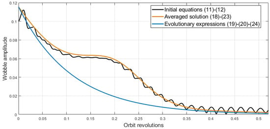
Figure 1.
Wobble amplitude.
- Inertia moments = 0.07 kg∙m2, = 0.05 kg∙m2;
- Orbit altitude 550 km (orbital rate = 10−3 s−1, geomagnetic induction vector approximate strength = 2.35∙10−5 T), inclination i = 57°;
- Satellite rotation rate = 2.1°/s (parameter that represents slow evolution of the geomagnetic field vector components ≈ 30);
- Nutation damping gain = 2∙105 N∙m∙s/T2, positional control gain = 2∙104 N∙m/T2, coefficient , derived small parameter ≈ 0.18;
- The geomagnetic induction vector in the frame is given by the expression (4) and the rotation matrix defined by three rotations (2-3-1 sequence) 30° each.
Figure 1 reveals the difference between three solutions in oscillatory behavior. Averaged expressions (18)–(23) quite accurately describe the wobble amplitude time history. Fast oscillations that arise due to the satellite rotation are eliminated from the consideration in the averaged solution. This solution accuracy lowers with time, especially when the amplitude is close to zero and oscillations start to play an important role in the wobble magnitude. The averaged solution is theoretically valid on time interval [32]. In the considered situation of the relatively high value of the small parameter, this interval comprises only about three minutes. However, the averaged solution successfully describes the transient process on a larger interval in Figure 1. Evolutionary expressions (19)–(24) are less accurate than the proper averaged solution. Essentially, the slow oscillation of the amplitude due to the geomagnetic induction vector rotation is eliminated from consideration. This drastically reduces the accuracy of the exact transient behavior prediction. However, the time necessary to achieve almost zero wobble amplitude is successfully predicted with the simplified evolutionary solution (19)–(24).
3.2.2. Offset Angles
The wobble amplitude analysis reveals specific expressions for the amplitude decay. These expressions also describe the spin axis oscillations in (14). Offset angles and should be analyzed to fully describe the spin axis motion. Averaged equations for these angles in (17) have the form
where , matrix is
where . Time transformation → leads to
where is
, , , . Note that product is not small. In the considered simulation example if . Parameter does not depend on the nutation damping control gain. The offset angles’ evolution is governed by the reorientation algorithm only, just as the wobble amplitude is governed by the nutation damping control. Matrix has the following properties:
- , . Equality is only observed at specific time moments.
- .
- , .
Properties 1 and 2 are used to prove the asymptotic stability of the equilibrium position . The Lyapunov candidate function is utilized. Its derivative according to (25) is
The function derivative is negative and equals zero at the equilibrium or when . The latter condition is satisfied only at specific moments. This condition is also satisfied on the equatorial orbit while the required direction is parallel with the Earth’s rotation axis. Excluding this specific orbit geometry, the equilibrium is asymptotically stable.
The degree of stability is determined using the Floquet theory [37] for the linear system with periodic coefficients (Property 3). Figure 2 introduces the larger characteristic multiplier and corresponding characteristic exponent.
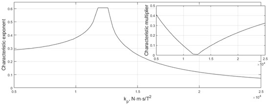
Figure 2.
Stability of the offset angles’ origin.
There is a small interval of optimum control gain values. Note that the stability is governed by the parameter which in turn depends on the relation . As a result, the optimum control gain value is directly related to the rotation rate.
4. Numerical Simulation
Fully nonlinear equations are numerically solved to verify the theoretical results’ applicability in a real satellite dynamics analysis. Arbitrary satellite motion requires an additional spinning algorithm
that drives the satellite to the required rotation rate. The control torque component along the first axis is . This component is always positive. However, disturbing components along other axes appear. The nutation damping control (9) effectively handles the arising wobble. If the satellite rotation rate is too high, control (26) is utilized in the opposite direction. Control switching logic is provided in Figure 3. Control (26) is termed “spinning” in Figure 3, while negative expression (26) is termed “damping”.
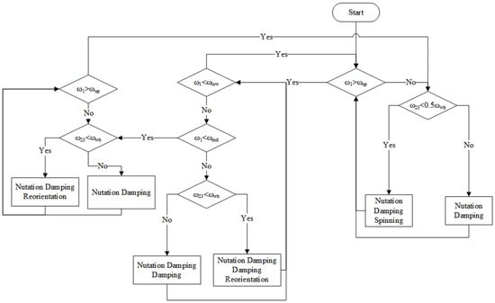
Figure 3.
Control switching logic.
There are two main blocks in Figure 3. The rightmost block is used to achieve the required rotation rate. It operates until the rotation rate reaches a predefined threshold value of . However, the spinning algorithm is utilized only at the acceptable wobble level lower than . Control switches to the left block when the rotation rate reaches and continues its operation until the rotation rate drops below a predefined value . The left block performs the satellite spin axis reorientation and the rotation rate maintenance in the range between and . The reorientation algorithm is switched on if the wobble level does not exceed a predefined value . Otherwise, only the nutation damping is performed. As a final note, the nutation damping algorithm is always active and suppresses the wobble arising due to the disturbing factors.
The control switching logic in Figure 3 is far from a simplified theoretical scenario considered in Section 3, when only nutation damping and reorientation laws are used in the vicinity of the required motion. However, the developed result provides a relatively accurate prediction of the control performance. Figure 4 illustrates the transient process duration with different control gains in the numerical simulation.
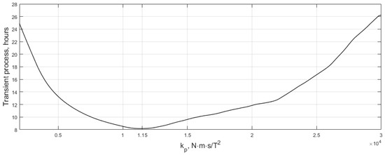
Figure 4.
Transient process duration dependence on the positional control gain.
Figure 4 was obtained with the same parameters as Figure 1 and Figure 2, spinning algorithm control gain is = 102 N∙m/T2, lower and upper bounds on the rotation rate are 2.0 and 2.1 degrees per second, and the wobble threshold is 2 min per second. The required attitude is achieved if the spin axis deviation from the designated direction is less than 0.01 degrees for 100 s. Note that the satellite is still axisymmetric and disturbances are not accounted for, so stabilization with the abovementioned high accuracy is achievable. Figure 4 provides an optimum positional control gain relatively close to the one reported in Figure 2.
Disturbances significantly affect the accuracy of the theoretical analysis results. Satellite asymmetry is the most prominent disturbing factor. An example of the satellite motion simulation is provided in Figure 5. Inertia moments of the satellite are 0.07, 0.055, and 0.045 kg∙m2. Gravitational and constant torques are acting on the satellite, with the latter having a magnitude of 5∙10−9 N∙m. The geomagnetic field is approximated with the IGRF model [38].
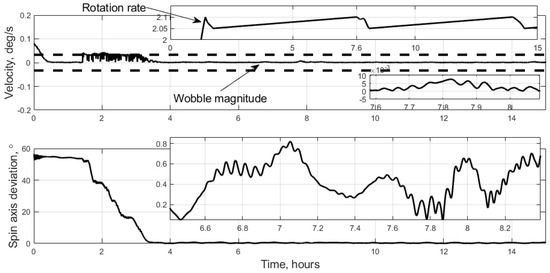
Figure 5.
Satellite motion example.
The nutation damping control gain is modified to = 1.2∙105 N∙m∙s/T to effectively counter the permanent satellite spin-up by the disturbing torque. The stabilization time dependence on the positional control gain is reported in Figure 6. The satellite stabilization accuracy criteria should be established to identify the moment of terminal stabilization. The satellite exhibits sudden increased deviations from the required attitude due to the disturbances, which are reported in a close-up in Figure 5. Therefore, two stabilization criteria are chosen. The first one characterizes the average accuracy: average deviation of the spin axis from the required direction should be less than 0.4° during half an hour. The second criterion characterizes the magnitude and duration of outliers: the deviation may exceed 0.5° not more than 10% of the time. These stabilization accuracy requirements are significantly weaker than the ones utilized in the simulation without disturbances in Figure 4. These requirements, as well as satellite and disturbance parameters that lead to relatively low expected accuracy, were chosen purposely to test the satellite behavior in unfavorable conditions.
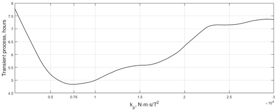
Figure 6.
Change in the transient process duration due to the disturbances influence.
Figure 6 differs significantly from Figure 2 and Figure 4. The total stabilization time decreases due to the lowered requirements on the accuracy. The optimal control gain changes substantially, mainly due to the satellite asymmetry. However, it is still close to the theoretically predicted, and the difference in the transient process time is relatively low for theoretical and real best gain values.
5. Conclusions
The spin stabilized satellite with magnetic actuation is considered in the vicinity of the required attitude. The approximate expression for the oscillations’ amplitude of the angular velocity component perpendicular to the rotation axis is established. The exponential decay of the wobble level is directly given by this expression. The transient process time depends on the orbit inclination, and high inclination always ensures a decent control performance. The deviation of the spin axis from the required direction in the inertial space is analyzed. The optimum control gain for the reorientation algorithm is established for the evolutionary equations using the Floquet theory. Exceeding the optimum value may drastically increase the reorientation maneuver time. This result is verified through the numerical simulation of the initial equations of motion with different disturbance sources. The theoretically established optimum control gain value requires adjustment with the numerical analysis under heavy disturbances, especially in the case of large inertia tensor uncertainty.
Author Contributions
Conceptualization, M.O.; methodology, M.O.; formal analysis, D.R.; writing—original draft preparation, D.R.; writing—review and editing, M.O. All authors have read and agreed to the published version of the manuscript.
Funding
This research received no external funding.
Data Availability Statement
Not applicable.
Acknowledgments
The authors would like to thank V.V. Sidorenko for the essential remarks on the theoretical analysis process.
Conflicts of Interest
The authors declare no conflict of interest.
References
- Lanchares, V.; Iñarrea, M.; Pascual, A.I.; Elipe, A. Stability Conditions for Permanent Rotations of a Heavy Gyrostat with Two Constant Rotors. Mathematics 2022, 10, 1882. [Google Scholar] [CrossRef]
- Sternberg, S.; Schnapf, A. Performance and Evaluation of Satellites Tiros I and Tiros II. ARS J. 1961, 31, 1495–1505. [Google Scholar] [CrossRef]
- Polat, H.C.; Virgili-Llop, J.; Romano, M. Survey, Statistical Analysis and Classification of Launched CubeSat Missions with Emphasis on the Attitude Control Method. J. Small Satell. 2016, 5, 513–530. [Google Scholar]
- Millan, R.M.; von Steiger, R.; Ariel, M.; Bartalev, S.; Borgeaud, M.; Campagnola, S.; Castillo-Rogez, J.C.; Fléron, R.; Gass, V.; Gregorio, A.; et al. Small satellites for space science: A COSPAR scientific roadmap. Adv. Sp. Res. 2019, 64, 1466–1517. [Google Scholar] [CrossRef]
- Slavinskis, A.; Kvell, U.; Kulu, E.; Sünter, I.; Kuuste, H.; Lätt, S.; Voormansik, K.; Noorma, M. High spin rate magnetic controller for nanosatellites. Acta Astronaut. 2014, 95, 218–226. [Google Scholar] [CrossRef]
- Alexandrov, A.Y.; Tikhonov, A.A. Electrodynamic Control with Distributed Delay for AES Stabilization in an Equatorial Orbit. Cosm. Res. 2022, 60, 366–374. [Google Scholar] [CrossRef]
- Kalenova, V.I.; Morozov, V.M. Stabilization of Satellite Relative Equilibrium Using Magnetic and Lorentzian Moments. Cosm. Res. 2021, 59, 343–356. [Google Scholar] [CrossRef]
- Aleksandrov, A.Y.; Andriyanova, N.R.; Tikhonov, A.A. Averaging Method in the Problem of the Lorentz Stabilization of the Indirect Equilibrium Position of a Satellite in the Orbital Coordinate System. Vestn. St. Petersbg. Univ. Math. 2021, 54, 95–105. [Google Scholar] [CrossRef]
- Thomson, W.T. Spin stabilization of attitude against gravity torque. J. Astronaut. Sci. 1962, 9, 31–33. [Google Scholar]
- Kane, T.R.; Shippy, D.J. Attitude stability of a spinning asymmetrical satellite in a circular orbit. J. Astronaut. Sci. 1963, 10, 114–119. [Google Scholar]
- Pringle, R. Bounds on the librations of a symmetrical satellite. AIAA J. 1964, 2, 908–912. [Google Scholar] [CrossRef]
- Likins, P.W. Stability of a symmetrical satellite in attitudes fixed in an orbiting reference frame. J. Astronaut. Sci. 1965, 12, 18–24. [Google Scholar]
- Beletsky, V.V. Motion of an Artificial Satellite about Its Center of Mass; Israel Program for Scientific Translation: Jerusalem, Israel, 1966. [Google Scholar]
- Avanzini, G.; de Angelis, E.L.; Giulietti, F. Spin-axis pointing of a magnetically actuated spacecraft. Acta Astronaut. 2014, 94, 493–501. [Google Scholar] [CrossRef]
- Avanzini, G.; de Angelis, E.L.; Giulietti, F. Acquisition of a Desired Pure-Spin Condition for a Magnetically Actuated Spacecraft. J. Guid. Control Dyn. 2013, 36, 1816–1821. [Google Scholar] [CrossRef]
- de Ruiter, A. A fault-tolerant magnetic spin stabilizing controller for the JC2Sat-FF mission. Acta Astronaut. 2011, 68, 160–171. [Google Scholar] [CrossRef]
- Chasset, C.; Berge, S.; Bodin, P.; Jakobson, B. 3-axis magnetic control with multiple attitude profile capabilities in the PRISMA mission. In Proceedings of the 57th International Astronautical Congress, Valencia, Spain, 2–6 October 2006; American Institute of Aeronautics and Astronautics: Valencia, Spain, 2006; p. IAC-06-C1.2.3. [Google Scholar]
- Shigehara, M. Geomagnetic attitude control of an axisymmetric spinning satellite. J. Spacecr. Rockets 1972, 9, 391–398. [Google Scholar] [CrossRef]
- Cubas, J.; de Ruiter, A. Magnetic control without attitude determination for spinning spacecraft. Acta Astronaut. 2020, 169, 108–123. [Google Scholar] [CrossRef]
- Crocker, M.C.; Vrablik, E.A. Experiment in solar orientation of spin stabilized satellite. AIAA J. 1965, 3, 1350–1351. [Google Scholar] [CrossRef]
- Roldugin, D.S.; Tkachev, S.S.; Ovchinnikov, M.Y. Satellite Angular Motion under the Action of SDOT Magnetic One Axis Sun Acquisition Algorithm. Cosm. Res. 2021, 59, 529–536. [Google Scholar] [CrossRef]
- Roldugin, D.S. Stability of a Magnetically Actuated Satellite towards the Sun on a Sun-Synchronous Orbit. Cosm. Res. 2023, 61, 134–142. [Google Scholar] [CrossRef]
- Janssens, F.L.; van der Ha, J.C. Flat-spin recovery of spinning satellites by an equatorial torque. Acta Astronaut. 2015, 116, 355–367. [Google Scholar] [CrossRef]
- Morozov, V.M.; Kalenova, V.I.; Rak, M.G. On the Stabilization of the Regular Precessions of Satellites by Means of Magnetic Moments. Mech. Solids 2021, 56, 1486–1499. [Google Scholar] [CrossRef]
- Ignatov, A.I.; Sazonov, V.V. Investigation of Steady-State Motion of an Artificial Earth Satellite in the Uniaxial Magnetic Orientation Mode. Cosm. Res. 2021, 59, 112–125. [Google Scholar] [CrossRef]
- Aleksandrov, A.Y.; Aleksandrova, E.B.; Tikhonov, A.A. Stabilization of a programmed rotation mode for a satellite with electrodynamic attitude control system. Adv. Sp. Res. 2018, 62, 142–151. [Google Scholar] [CrossRef]
- Cubas, J.; Farrahi, A.; Pindalo, S. Magnetic Attitude Control for Satellites in Polar or Sun-Synchronous Orbits. J. Guid. Control Dyn. 2015, 38, 1947–1958. [Google Scholar] [CrossRef]
- Cheon, Y.; Lee, S.; Kim, J. Fully Magnetic Devices-Based Control for Gyroless Target Pointing of a Spinning Spacecraft. IEEE Trans. Aerosp. Electron. Syst. 2010, 46, 1484–1491. [Google Scholar] [CrossRef]
- Ovchinnikov, M.Y.; Penkov, V.I.; Roldugin, D.S. Study of a bunch of three algorithms for magnetic control of attitude and spin rate of a spin-stabilized satellite. Cosm. Res. 2012, 50, 304–312. [Google Scholar] [CrossRef]
- Arnold, V.I.; Kozlov, V.V.; Neishtadt, A.I. Dynamical Systems III: Mathematical Aspects of Classical and Celestial Mechanics; Springer: Berlin/Heidelberg, Germany, 2007. [Google Scholar]
- Aleksandrov, A.Y.; Tikhonov, A.A. Averaging technique in the problem of Lorentz attitude stabilization of an Earth-pointing satellite. Aerosp. Sci. Technol. 2020, 104, 105963. [Google Scholar] [CrossRef]
- Bogoliubov, Y.A.; Mitropolsky, N.N. Asymptotic Methods in the Theory of Nonlinear Oscillations; Gordon and Breach: Philadelphia, PA, USA, 1961; ISBN 067720051X. [Google Scholar]
- Wertz, J.R. Spacecraft Attitude Determination and Control; Academic Press: Dordrecht, The Netherland; Boston, MA, USA; London, UK, 1990. [Google Scholar]
- Ovchinnikov, M.Y.; Penkov, V.I.; Roldugin, D.S.; Pichuzhkina, A.V. Geomagnetic field models for satellite angular motion studies. Acta Astronaut. 2018, 144, 171–180. [Google Scholar] [CrossRef]
- Antipov, K.A.; Tikhonov, A.A. Multipole models of the geomagnetic field: Construction of the Nth approximation. Geomagn. Aeron. 2013, 53, 257–267. [Google Scholar] [CrossRef]
- Stickler, A.C.; Alfriend, K.T. Elementary Magnetic Attitude Control System. J. Spacecr. Rockets 1976, 13, 282–287. [Google Scholar] [CrossRef]
- Malkin, I.G. Theory of Stability of Motion; U.S. Atomic Energy Commission, Technical Information Service: Oak Ridge, TN, USA, 1952. [Google Scholar]
- Alken, P.; Thébault, E.; Beggan, C.D.; Amit, H.; Aubert, J.; Baerenzung, J.; Bondar, T.N.; Brown, W.J.; Califf, S.; Chambodut, A.; et al. International Geomagnetic Reference Field: The thirteenth generation. Earth Planets Space 2021, 73, 49. [Google Scholar] [CrossRef]
Disclaimer/Publisher’s Note: The statements, opinions and data contained in all publications are solely those of the individual author(s) and contributor(s) and not of MDPI and/or the editor(s). MDPI and/or the editor(s) disclaim responsibility for any injury to people or property resulting from any ideas, methods, instructions or products referred to in the content. |
© 2023 by the authors. Licensee MDPI, Basel, Switzerland. This article is an open access article distributed under the terms and conditions of the Creative Commons Attribution (CC BY) license (https://creativecommons.org/licenses/by/4.0/).