Article

Rectangular Cylinder Orientation and Aspect Ratio Impact on the Onset of Vortex Shedding

1
Department of Mathematics, Air University, Islamabad 44000, Pakistan
2
Department of Mathematics & Statistics, Women University Swabi, Swabi 23430, Pakistan
3
Department of Software Engineering and Research Chair of Smart Technologies, College of Computer and Information Sciences, King Saud University, Riyadh 11574, Saudi Arabia
*
Author to whom correspondence should be addressed.
Mathematics 2023, 11(22), 4571; https://doi.org/10.3390/math11224571
Submission received: 28 September 2023 / Revised: 20 October 2023 / Accepted: 23 October 2023 / Published: 7 November 2023
(This article belongs to the Special Issue Computational Mathematics and Numerical Analysis with Applications)

Abstract

:
Rectangular cylinders have the potential to provide valuable insights into the behavior of fluids in a variety of real-world applications. Keeping this in mind, the current study compares the behavior of fluid flow around rectangular cylinders with an aspect ratio (AR) of 1:2 or 2:1 under the effect of the Reynolds number (Re). The incompressible lattice Boltzmann method is used for numerical computations. It is found that the flow characteristics are highly influenced by changes in the aspect ratio compared to the Reynolds number. The flow exhibits three different regimes: Regime I (steady flow), Regime II (initial steady flow that becomes unsteady afterward), and Regime III (completely unsteady flow). In the case of the cylinder with an aspect ratio of 2:1, vortex generation, variation in drag, and the lift coefficient occur much earlier at very low Reynolds numbers compared to the cylinder with an aspect ratio of 1:2. For the cylinder with an aspect ratio of 1:2, the Reynolds number ranges for Regimes I, II, and III are 1 Re 120, 121 Re 144, and 145 Re 200, respectively. For the cylinder with an aspect ratio of 2:1, the Reynolds number ranges for Regimes I, II, and III are 1 Re 24, 25 Re 39, and 40 Re 200, respectively. The cylinder with an aspect ratio of 1:2 is found to have the ability to stabilize the incoming flow due to its extended after-body flatness. Generally, it has been found that a cylinder with an AR of 2:1 is subjected to higher pressures, higher drag forces, higher curvatures of cross-flow rotations, and higher amplitudes of flow-induced drag, as well as higher lift coefficients and lower shedding frequencies, compared to cylinders with an AR of 1:2. In Regime III, elliptic and vertically mounted airfoil-like flow structures are also observed in the wake of the cylinders.

1. Introduction

The term “bluff body” refers to a solid object that often interacts with the fluids passing around it. In recent decades, the analysis of bluff body flows has revealed several important outcomes. These bodies generally have geometric shapes, such as circles, squares, rectangles, and triangles. As a result of fluid separation and reattachment around bluff bodies, interesting fluid dynamics phenomena emerge. The study of such fluid flows is relevant to various fields, including aerospace engineering, civil engineering, and marine engineering. Many parameters, including the Reynolds number, the angle of incidence ( θ ) of the incoming fluid, the flow entrance, the exit boundary’s location, the blockage ratios (B), and the geometrical shapes (e.g., circular or square) of the bodies, have much influence on bluff body flow characteristics.
Previous studies have highlighted how changing these parameters can lead to different flow regimes, with a significant impact on fluid forces, vortex shedding, and flow structures [1,2,3,4,5,6,7,8,9,10]. Hamane et al. [1] investigated the vorticity structures in a circular cylinder’s wake at different Reynolds numbers of 20, 40, 100, and 3000 using the lattice Boltzmann method (LBM). They observed the steady-state flow at Re = 20 and 40, while at a Re of 100, vortex shedding appeared. Due to the vortex shedding, the drag and lift became periodic, with the frequency of drag being double that of the lift force ( f l ). They attributed the lift variations to vortex shedding instead of pressure variations, which mainly affect the drag force ( f D ).
Park et al. [2] studied the flow past a circular cylinder at Re up to 160 using high-resolution steady calculations. They reported an inverse relationship between the Re and drag coefficient (CD), while the pressure drag coefficient (CDP) decreased in steady flow but increased in unsteady flow. A fluid flow analysis around a two-dimensional (2D) circular cylinder at various Re values with different incidence angles ( θ s ) of 0°, 50°, and 100° was performed by Mehdi et al. [3]. They depicted the pressure (P), CD, and vortex shedding at different Re values and θs and found a direct relationship between Re, θ, and P.
The impact of side boundary locations on 2D flow past a circular obstacle was investigated by Behr et al. [4]. They reported the significant impact of near-boundary locations on the Strouhal number (St) and vortex shedding. Yoon et al. [5] analyzed the flow over a square-shaped cylinder for 5 ≤ Re ≤ 150 and θs ranging from 0° to 45°. According to the authors, the flow separation points and the critical Re were directly related to the θ. Jiang et al. [6] conducted a similar study by analyzing the flow separation from a square cylinder. Their results revealed that at certain moderate Re values, the flow was not seen to separate from corners. The location of the separation point moved gradually to the front edges as the Re value increased. Islam et al. [7] systematically inspected the influence of the locations of domain boundaries on the flow past a square cylinder with a Re value of 100. They found that with the placement of the cylinder nearer to the inlet boundary location, the physical quantities such as the mean drag coefficient ( C D m e a n ) , the root mean square value of the lift coefficient ( C L r m s ) , and the St reached their maxima. According to the authors, for a smooth vortex shedding phenomenon, the downstream boundary location must be sufficiently large.
The flow past a square obstacle in a channel with a blockage ratio (B) of 1/8 for 0.5 Re 300 was analyzed by Breuer et al. [8]. They concluded that the increasing Re values result in the separation of the laminar boundary layer from the cylinder surface due to the weakening effects of viscous forces. Kelkar and Patankar [9] numerically simulated the 2D vortex shedding characteristics around a square cylinder at different Re values. They found that an increase in Re results in alterations in the size and strength of the recirculation regions of the detached shear layers. Sohankar et al. [10] considered unsteady flow in the case of a square cylinder at θs ranging from 0° to 45° and Re values ranging from 45 to 200. They concluded that the flow structure and the stagnation pressure coefficient ( C P ) were significantly affected by changing the θ and the Re.
The previous studies also indicated the significant influence of aspect ratios (ARs) on bluff body flows. The AR defines the dimensions of bluff bodies, such as cylinders, cubes, or spheres. In some cases, this parameter has severe effects on the flow structures and fluid forces compared to the previously described fluid flow-affecting parameters. There have been various investigations regarding the impact of changing aspect ratios on fluid flows around bluff bodies. Islam et al. [11] investigated the impact of the AR on fluid forces around a rectangular cylinder at Re values of 100, 150, 200, and 250. They found an inverse relationship between CD and AR. Ahmed et al. [12] conducted a numerical study on rectangular cylinders with ARs ranging from 0.03 to 1 and Re ranging from 75 to 150. Discontinuity in the St was reported in that study at Re = 145 and 150 for 0.5 ≤ AR ≤ 0.6. Sohankar et al. [13] investigated the unsteady flow around a rectangular cylinder at θs ranging from 0° to 45° with ARs ranging from 1 to 4 and Re values of 200 . It was found that the point of separation of the flow changed when the Re changed. Further, the authors observed fully attached separation bubbles for AR > 2. Ohya [14] presented the base pressure ( B P ) measurements on a rectangular cylinder with an AR in the range of 0.4 to 0.6. He found that the variation magnitude in B P was low at an AR of 0.5, while a high magnitude was observed at ARs of 0.4 and 0.6, due to a sudden change in the flow pattern around the cylinder. Bearman and Trueman [15] experimentally examined the B P , CD, and St around a rectangular cylinder. They reported the maximum CD at an AR of 0.6. Sohankar [16] simulated the flow around a rectangular cylinder with different ARs at a Re of 105. He observed that the St decreased with increasing AR.
In addition to single bluff body flow, multiple bluff body flows have also been analyzed in some studies in the past. Islam et al. [17] explored the effect of gap ratios (G) on flow around rectangles placed inline. They found that the upstream cylinder faced higher f D as compared to the downstream one. The effect of G on flow past five rectangular cylinders placed side-by-side was explored by Islam et al. [18] at Re = 150 and AR = 1.5. It was observed that the cylinders’ wakes were significantly affected by the G, resulting in five distinct flow patterns. The flow structure in this case was found to be different from that of the square cylinder. Rahman et al. [19] performed numerical simulations regarding the effects of the AR and R e on the flow around three rectangular cylinders with fixed G = 1.5. They found that a smaller AR results in higher f D and lower vortex shedding frequencies, while a larger AR leads to the opposite trends. Islam et al. [20] discussed the effect of AR ranging from 0.25 to 3 and G ranging from 0.5 to 7 on the flow characteristics of three inline rectangular cylinders with fixed Re = 150. The results showed that the AR strongly affected the force coefficients ( C f ) of the cylinders. In another study, Islam et al. [21] investigated the impact of changing G on the flow around three rectangular rods with a fixed AR = 0.25 at Re = 150. According to their findings, G has a significant influence on the flow behavior. Besides the rectangular bodies, there have also been several investigations into the flow characteristics around multiple circular/square-shaped bodies in the flow field [22,23,24,25,26].
From the preceding discussions, it can be inferred that the fluid flow analysis around rectangular cylinders is much less emphasized as compared to their circular/square counterparts. Specifically, studies related to the flows around vertically mounted rectangular cylinders are rarely found in the literature. Emphasizing this shortcoming, the present study is devoted to the numerical investigations of flow regime variations around rectangular cylinders with different aspect ratios. The present work’s novelty lies in the usage of the lattice Boltzmann method to simulate fluid flow around cylinders with varying AR and Re. In particular, two cases of aspect ratio are considered in the current analysis: the first case is concerned with the aspect ratio 1:2, i.e., the width of the cylinder is double its height; the second case is when the width of the cylinder is half its height, i.e., AR = 2:1. How the change in AR and Re affects the patterns of flow will be taken into account, as well as how the geometry of the cylinders influences different flow states. The AR effects on vortex structures, the St, and the fluid force coefficients will be provided both qualitatively and quantitatively in this work.

2. Numerical Methodology

The results of this work are numerically computed utilizing the lattice Boltzmann method (LBM). This is a relatively new and common discrete numerical approach for simulating fluid flow problems. It bridges the gap between micro- and macro-scales of simulations. It has been found to be very efficient as compared to traditional CFD solvers. The working rules of the LBM originate from the lattice gas cellular automata (LGCA). This approach was introduced by McNamara and Zanetti [27] with a focus on addressing the statistical noise problem that appeared in the LGCA. There are several reasons for its popularity: for example, as it possesses the characteristics of both macro- and micro-level scales, it is easily implementable, it can handle complex geometries, and it has parallel computing abilities due to the locality of streaming and collision processes. To check its efficacy, Guo et al. [28] compared LBM results with the gas-kinetic scheme (GKS) for the flow around a square cylinder. They reported the LBM to be 10 times faster than the GKS for steady flows and about 3 times faster for unsteady flows. The LBM has its roots in the famous Boltzmann equation (BE) [29], which is given as follows:
f t + e . f = Ω
where e is the velocity vector and f and Ω are the probability distribution function and collision term, respectively. With the Bhatnagar, Gross, and Krook (BGK) approximation [30] for the collision process, Equation (1) becomes the following:
f t + e . f = 1 τ f f e q
where f e q is the equilibrium distribution of particles and τ is the relaxation time factor. It serves as the stability controlling parameter associated with the kinematic viscosity as v = c s 2 ( τ 1 2 ) and c s is the lattice sound speed with values c s = 1 3 and τ > 0.5 for the D2Q9 model [30,31]. In computational fluid dynamics simulations, the discrete BE given below replaces the so-called Navier–Stokes equation (NSE).
f i x + e i Δ t , t + Δ t f i x , t = 1 τ f i x , t f i e q x , t
where x, t, and Δ t are the particle position, simulation time, and time step, respectively. In Equation (3), the left and right sides indicate the streaming and collision terms, respectively. In the current work, we have performed computations based on the D2Q9 (D for dimension and Q for number of particles) model for simulations (Figure 1).
The equilibrium distribution function in Equation (3) has the general form of
f i e q = ϕ   w i [ A + B e i   . u + C e i   . u 2 + D u 2 ]
More specifically, in the D2Q9 model, it takes the following form:
f i e q = ρ   w i [ 1 + 3 e i   . u + 9 2 e i   . u 2 3 2 u 2 ]
where ρ is density, u is fluid velocity, and w i represents weighting coefficients. The w i for the D2Q9 model is given below:
w i =   4 9 i = 0 1 9   i = 1 , 2 , 3 , 4   1 36     i = 5 , 6 , 7 , 8
The discrete velocity directions e i involved in the above equations for the D2Q9 model are given as follows:
e i = ( 0 , 0 ) , i = 0 cos ( i 1 ) π / 2 , sin ( i 1 ) π / 2 , i = 1 , 2 , 3 , 4 2 cos ( 2 i 9 ) π / 4 , sin ( 2 i 9 ) π / 4 , i = 5 , 6 , 7 , 8
In LBM simulations, the relations for macroscopic velocity and density are as follows:
ρ = i = 0 8 f i
ρ u = i = 0 8 e i f i

3. Problem Description, Grid Independence, and Code Validation

The schematic of the problem under consideration is given in Figure 2. This figure illustrates a fixed rectangular cylinder placed inside a channel with length X and width Y. Here, we will consider two aspect ratios for the cylinder: AR = h/d = 1:2 and 2:1, where d is the width and h is the height of the cylinder. Specifically, AR = 1:2 indicates that the width of the cylinder is double its height, while AR = 2:1 indicates that the width of the cylinder is half its height. In AR = 2:1, the cylinder is mounted vertically, while for AR = 2:1, the cylinder is placed horizontally. Note that in the case of AR = 1:2, the cylinder is divided into 10 lattices height-wise, while in the case of AR = 2:1, the cylinder contains 40 lattices height-wise. In both cases, the width, d, is divided into 20 lattices. A domain size with X u = 10d upstream, X d = 20d downstream, and a distance of Y u = Y d = 8d is selected for lateral boundaries from the cylinder. This domain size is sufficient in terms of the accuracy of the solution and computational cost independent of domain effects for flow past a cylinder [11,12].

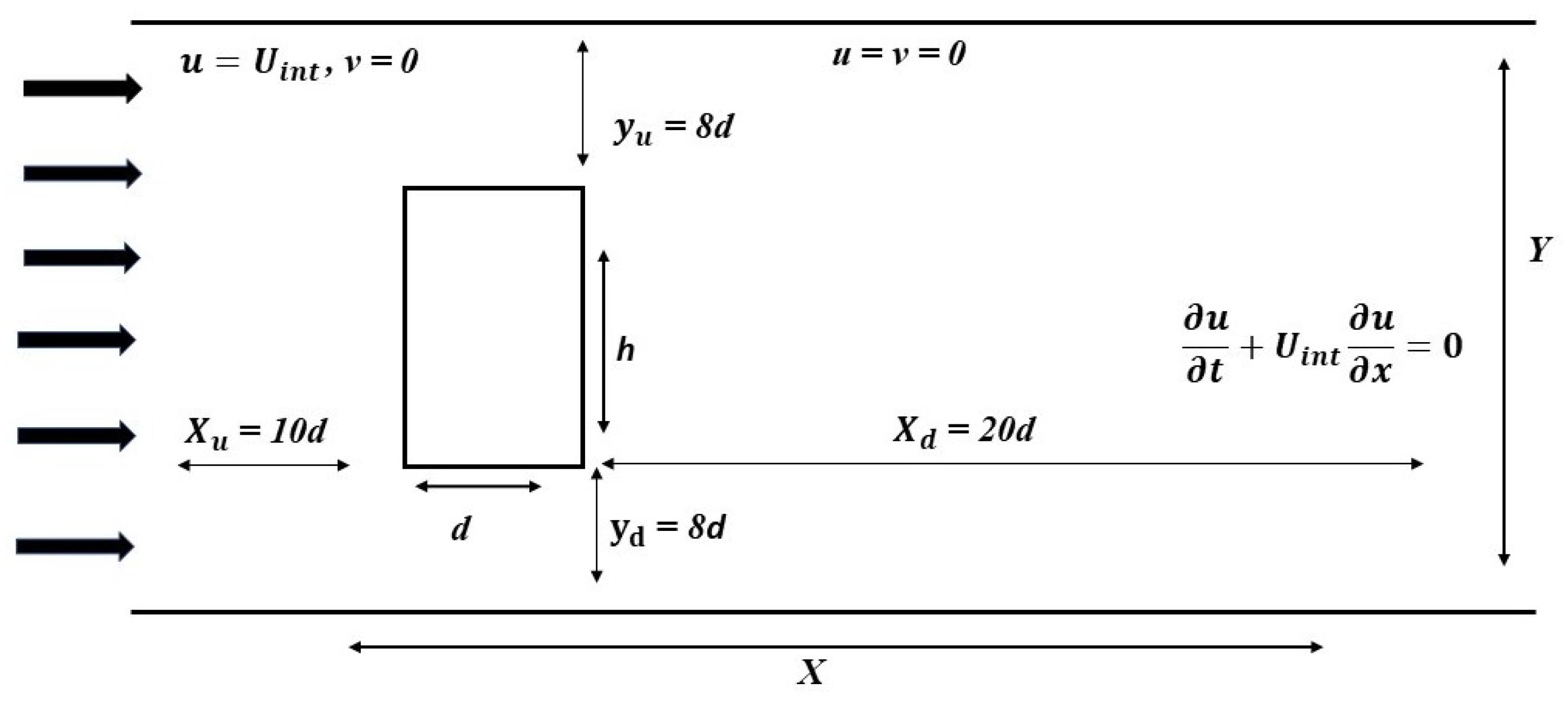
3.1. Boundary Conditions

Inlet boundary: Uniform inflow with velocity U i n t is considered at the inlet boundary; that is:
u = U int , v = 0
Outlet boundary: The convective boundary condition is considered at the outflow boundary so that the flow leaves the boundary, thus conserving the momentum. Mathematically, it is expressed as follows:
  u   t + U int     u   x = 0
Solid walls: Top and bottom boundaries and the cylinder surface are handled with no-slip boundary conditions. This condition is adopted through the so-called bounce-back rule in which all particles striking the solid wall reflect in the opposite direction. The mathematical form of this boundary condition is as follows:
u = 0 , v = 0

3.2. Grid Independence

The grid independence study is an important aspect of the computational fluid dynamics. Through this study, a suitable grid size is selected to ensure a balance between accuracy and computational time. For this purpose, we tested three different grid sizes (10 points, 20 points, and 40 points) along a square cylinder surface at Re = 100. The computed results indicate that the physical parameters are significantly affected by the 10-point grid, with a large percentage difference from the 40-point grid results (see Table 1). The 20-point grid is able to produce more accurate results than the 10-point grid, while the 40-point grid takes a longer time to converge and does not show as much improvement over the 20-point grid. Therefore, we have taken the 20-point grid size for our future analyses.

3.3. Code Validation

It is important to mention here that the current numerical study utilizes an in-house developed code based on the FORTRAN language. For the validation of this code, we conducted simulations for flow around a single square cylinder at Re = 100. When compared to other studies, a strong agreement can be witnessed between our results and other researchers’ results (Table 2). This indicates that our code is efficient in calculating important fluid flow parameters. The minor discrepancies in results are due to different reasons. For example, it is obvious that the accuracy of underlying numerical schemes affects the results. Some further parameters affecting the results include the selected grid size, the domain size, and the position of the obstacle with respect to incoming flow, etc. Due to this, it is almost impossible to obtain results that match other studies without any differences. Thus, minor discrepancies always occur in the results, and this is why our data for code validation display minor differences to those of other researchers. However, there is a good agreement within the overall range of values. This level of agreement indicates that our code is suitable for the accurate computation of fluid flow parameters.

4. Results and Discussion

The numerical computation results for the fluid flow past the rectangular cylinder with AR = 1:2 and 2:1 are presented and discussed in this section. In both cases, the Re varied in the range of 1 to 200. Our emphasis is on the observation of the flow mode transition under the effects of Re and AR. In this study, three main flow regimes emerge around the cylinder in both AR cases. These flow regimes are categorized based on the different flow states as the Reynolds number is systematically varied. In particular, the flow regimes are classified qualitatively in terms of vorticity contours, streamline behavior, variations in the drag and lift coefficients, phase plots, and power spectrum of lift coefficients. Regime I corresponds to the steady flow mode in which the flow remains steady for the entire computational time with no vorticity and constant flow-induced forces. Regime II corresponds to the transient flow mode in which the flow is initially steady but later exhibits unsteadiness. In this flow regime, the fluid forces remain constant for a longer amount of computational time and then vary after that. Regime III corresponds to the unsteady flow mode in which the vortices appear in the wake with fluctuating fluid forces at comparatively earlier stages of computational time. Note that in general, the Reynolds number is varied at the intervals with step size 5 in the current work. However, where transitions occur, simulations are also performed for the Reynolds number between the intervals in order to exactly locate the value of the critical Reynolds number where the flow regime changes. Further, to avoid repetition, only the representative cases of each of the flow regimes are presented and analyzed.

4.1. Regime I

The discussion of the characteristics of the flow Regime I for both cases of aspect ratio is presented in this section. That is, when the width of the cylinder is double its height, i.e., AR = 1:2, and when the width of the cylinder is half its height, i.e., AR = 2:1. As discussed earlier, Regime I corresponds to the steady flow state. Its representative vorticity contours, pressure streamline contours, and drag and lift variations with time for both AR cases are shown in Figure 3 at Re = 1. This flow regime appeared at very low Re values for both AR cases. Since the Re is very low, the shear layers remain attached to the cylinder in the form of bubbles due to dominating viscous effects (Figure 3a,b). The cylinder with a higher AR has larger recirculating attached bubbles compared to the cylinder with a low AR. The dashed and solid lines in the vorticity contours correspond to the anticlockwise and clockwise rotations in the flow. The steady flow indicates the absence of vorticity or cross-flow variation due to the dominance of viscosity effects. Due to the steadiness in flow, the streamlines depicted in Figure 3c,d exhibit a constant flow behavior in the wake. The flow seems to detach from the front corners of the cylinder in both aspect ratio cases (Figure 3c,d). These figures also indicate that there are no significant pressure differences because of no variations in the flow state. Higher pressure appears at the front side of each cylinder, which is reduced in the wake region. Moreover, due to the lack of vorticity and the absence of significant pressure variations, the CD and CL remain unchanged, as illustrated in Figure 3e–h. Note that the CD and CL are plotted against the non-dimensional time T = (Uint t/d). The cylinder with an AR = 2:1 has a higher drag force as compared to that with an AR = 1:2 (Figure 3e,f). This difference in drag force is due to the different cross-sectional areas of both bodies. On the other hand, the lift coefficient value remains the same for both bodies due to a steady flow. It is worth mentioning here that due to the steady flow, the power spectrum as well as the phase diagram analysis is not possible. Note that the Regime I for AR = 1:2 spans over the range 1 Re 120, while in the case of AR = 2:1, it spans the range of 1 Re 24. Similar flow characteristics around a square cylinder were also reported by Hamane et al. [1] and Kelkar and Patankar [9].

4.2. Regime II

As mentioned above, the range of Reynolds numbers is different in the case of the flow Regime I in both aspect ratio cases. This means that the change in AR has a significant impact on the change in flow regimes. This is similar in the case of flow Regime II. When the Reynolds number reaches the value of 121 for AR = 1:2 and Re = 25 for AR = 2:1, Regime I no longer exists and the flow mode changes to Regime II. This flow regime corresponds to the transient state of the fluid flowing around the cylinder. The shear layers in this case tend to reach the exit position of the channel instead of remaining attached to the cylinder, as was observed in Regime I. This is due to an increase in Reynolds number values, which results in weakening the viscous forces effect. The vorticity contour, pressure streamlines, drag coefficient, lift coefficient, power spectrum, and phase diagrams for Regime II are presented in Figure 4. It can be seen that although the vortices do not develop behind the cylinder with AR = 1:2 at Re = 121, minor cross-flow variations instead appear near the exit point of the domain (Figure 4a). However, with AR = 1:2, the vortices appear at Re = 25 (Figure 4b). Comparing both these cases, it can be observed that for the vertically mounted cylinder (AR = 1:2), the unsteadiness in the flow appears much earlier as compared to the horizontally placed cylinder (Figure 4a,b). This transient behavior of flow is more apparent in the streamline graphs shown in Figure 4c,d. In the case of AR = 1:2, the streamlines show transient behavior with two symmetrical eddies in the wake near the back side of the cylinder, while for AR = 2:1, the streamline graphs show transient behavior with two eddies of different sizes. The smaller eddy is generated at the lower corner of the trailing surface, while the large eddy is generated in the middle region near the trailing surface of the cylinder. Further, the pressure distributions also differ in both AR cases. In the case of AR = 1:2, the maximum pressure is near the front lower corner of the cylinder, while for AR = 2:1, the maximum pressure can be observed at the front surface of the cylinder. This is attributed to the fact that the former is subjected to a small amount of fluid due to the relatively smaller height, while the latter is subjected to a much higher amount of incoming fluid due to the increased height of the cylinder. Additionally, it is shown in Figure 4e that there is no change in CD over time for AR = 1:2 compared to the AR = 2:1 case, where CD shows an increasing trend after some time (Figure 4f). The impact of the transient flow state is more visible in the case of CL (Figure 4g,h). It can be observed that the CL displays transient behavior with initial steadiness and later variations due to instability in the flow in both AR cases. The oscillation amplitude of CL for the AR = 1:2 case is higher than in the AR = 2:1 case. Subsequently, the St is generated due to oscillations of the CL and is calculated using fast Fourier transform (FFT) (Figure 4i,j). It can be observed that the peak value of the spectrum energy graph indicates that the St is 0.1983 and 0.0674 in AR = 1:2 and 2:1, respectively. The higher value of St corresponds to the higher amplitude of CL curves while the lower one indicates smaller amplitude curves. The phase diagram with variations in CL against CD, corresponding to both AR cases, is shown in Figure 4k,l. The phase diagram clearly describes the Regime II case, as seen from the vorticity contours. It represents the vorticity appearance in AR = 2:1, while in AR = 1:2, it indicates minor oscillations and their resulting impacts on drag and lift patterns.

4.3. Regime III

When the Re of flow reaches a value of 145 for the cylinder with an AR = 1:2 and Re = 40 for the AR = 2:1 case, the transient state of flow changes to a completely unsteady state. This flow state is named Regime III in the current study. In this regime, the fully developed flow layers detaching from cylinders result in the complete generation of vortices moving alternately in the wake of cylinders. The corresponding vorticity contour, pressure streamlines, CD, CL, power spectrum of CL, and phase diagram for Regime III are revealed in Figure 5. From Figure 5a,b, it is evident that the fully developed vortices exhibit alternate movement, commonly termed the von Karmann vortex street. The curvature of cross-flow rotations is higher in the case of AR = 2:1 as compared to AR = 1:2. Note that in the initial stages of Regime III, comparatively weaker vortices appear in the wake. With the increment in Re values, the relative strength of the vortices increases, which results in an increase in the amplitudes of flow-induced forces. Figure 5c,d demonstrate that the streamlines corresponding to the flow show curvy behavior due to vorticity generation in the wake. For the case with AR = 1:2, the symmetric bubbles that appeared in the wake of the cylinder for the Regime II case no longer exist due to unsteadiness in the flow. Instead, recirculating elliptic or vertically mounted airfoil shapes such as eddies appear in the near wake region of the cylinder. The structures of these eddies are different in both AR cases. The streamlines’ contours also indicate that AR = 2:1 causes more disturbance in the surrounding fluid flow in comparison to the 1:2 case. Due to this disturbance, for the AR = 2:1 case, the amplitudes of flow-induced drag as well as lift coefficients become sufficiently higher as compared to the 1:2 aspect ratio case (Figure 5e–h). Both these force coefficients start periodic behavior at earlier stages as compared to Regime II. The higher amplitude of CL curves results in a smaller vortex shedding frequency (St = 0.0825), while the low-amplitude cycles result in higher shedding frequencies (St = 0.2196), as indicated by the power spectrum of CL for AR = 1:2 and 2:1, respectively (Figure 5i,j). Further, these figures also indicate that the vertically mounted cylinder (AR = 2:1) has higher spectrum energy, while the horizontally placed cylinder (AR = 1:2) has low spectrum energy. The phase diagrams shown in Figure 5k,l illustrate the periodic flow that results in the cyclic variations of both CD and CL in both AR cases.
Table 3 describes the complete picture of the Reynolds number range for all three flow regimes (steady, transient, and unsteady) observed in this study corresponding to both AR cases. It is evident from this table that for AR = 1:2, the flow exhibits steady behavior (Regime I) from Re = 1 to 120. This implies that the flow remains relatively stable and predictable within this range of Re for AR = 1:2. On the other hand, when AR = 2:1, the steady flow regime spans the Re range from 1 to 24, which is a comparatively low range of Re when compared to the AR = 1:2 case. This is similar to the cases of flow Regimes II and III as well and suggests that an AR = 1:2 is more suitable for stabilizing the incoming fluid than an AR = 2:1. In the case of AR = 2:1, the unsteadiness in flow starts much earlier due to its vertical placement. It resists large amounts of incoming fluid, and due to its shorter width, it is unable to stabilize the shear layers. Guo et al. [36] also categorized the flow around a square cylinder into three phases. According to them, in phase I, no vortex shedding appeared and lift remained zero; in phase II, vortex shedding and lift oscillations started and enhanced with Re; and in phase III, stable vortex shedding occurred. According to other studies, the flow around a square cylinder remains steady in the range from Re = 1 to 47, is transient in the range of Re = 48 to 53, and becomes completely unsteady beyond this value of Re [10,37]. According to Kelkar and Patankar [9], the onset of vortex shedding around a square cylinder starts at Re = 53. This shows that the change in AR has a significant effect on the flow mode transitions around sharp-edged bodies. These findings are also consistent with those of Rastan et al. [38]. According to these authors, the critical Re for the onset of vortex shedding is lower in cases of vertical flat plates than in square cylinders.

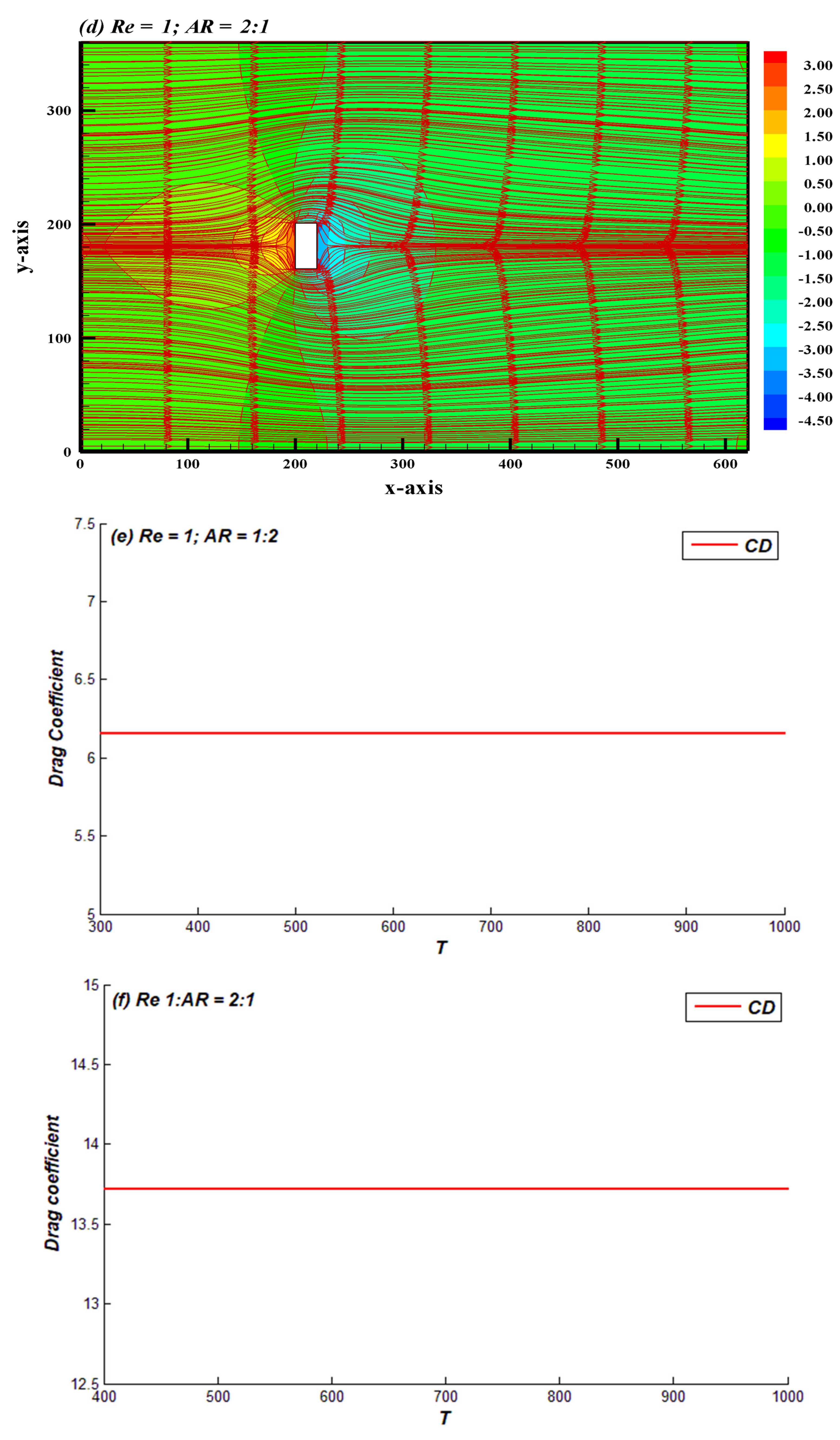
5. Force Statistics: Comparison between AR = 1:2 and 2:1

The comparative analysis of fluid force parameters, including C D m e a n , St, amplitude of drag coefficient ( C D a m p ), and amplitude of lift coefficient ( C L a m p ), in both aspect ratio cases revealed that the change in AR significantly affects the fluid forces. The variation in these force parameters against different values of Re, ranging from 1 to 200, is demonstrated in Figure 6. It should be noted that in both cases, the C D m e a n is higher initially due to the dominance of viscosity effects (Figure 6a). It decreases sharply in the range of low Re = 1–19, but later, for AR = 2:1, it exhibits a slight increasing behavior until reaching 200. Note that after this value of Re, the flow regime changes from Regime I to Regime II in the AR = 2:1 case, while for AR = 1:2, C D m e a n is almost constant until Re = 200. This difference in the variation of the magnitude of C D m e a n can be attributed to the difference in aspect ratios of cylinders. The cylinder with a higher aspect ratio bears more unsteadiness in the flow, and thus more fluctuations in the fluid forces occur. Further, the graph also shows a higher average drag coefficient for AR = 2:1 as compared to AR = 1:2 for all values of Re. This is because the unsteadiness in the flow starts much earlier and is more significant in the case of AR = 2:1, as discussed previously. Rastan et al. [38] reported in their study that the average drag force decreases with Re for AR > 0.5, and an opposite trend occurs for AR < 0.5 in the range of Re = 40 to 100. In the present case, at AR = 1:2, the CDmean remains almost constant, while for AR = 2:1, it increases with Re in the range from 40 to 100. Figure 6b depicts the effect of Re as well as AR on St. Note that for Regime I (steady flow), the computation of St is not possible due to cross-flow variations. With the increase in Re, the St for AR = 1:2 rapidly changes compared to that of AR = 2:1. In addition, greater values of St can be witnessed for AR = 1:2 compared to AR = 2:1. This indicates that the vortices shedding from the higher aspect ratio cylinder have a low frequency, while those from the lower AR cylinder have a higher shedding frequency. Figure 7a–d show the behavior of C D a m p and C L a m p against Re for both aspect ratios of the cylinder. It is apparent from these figures that for Regime I, the C D a m p and the C L a m p are zero due to the constant drag coefficient. The amplitudes of both of these force coefficients are higher for AR = 2:1 as compared to the 1:2 aspect ratio case. In addition, for both Regimes II and III, the amplitudes of drag as well as the lift coefficient increase with the increase in Re, indicating the higher fluctuations of these forces due to dominating inertial forces.

6. Conclusions

In this work, we compared the behavior of fluid flow characteristics around rectangular cylinders with aspect ratios (ARs) = 1:2 and 2:1 under the effect of Reynolds numbers. Reynolds numbers were varied within the range of 1 to 200, and the computations were performed using the lattice Boltzmann method. Our main emphasis was to detect the onset of vortex shedding depending on the Reynolds number for both aspect ratios. This study indicates that the onset of vortex shedding was much more dependent on AR instead of Re. Flow characteristics drastically changed by changing the aspect ratios of cylinders. For the aspect ratio 2:1, the onset of vortex shedding and fluid force variations occurred much earlier at very low Reynolds numbers, while for the case of the 1:2 aspect ratio, the vortex generation began at comparatively high Reynolds numbers. The cylinder with the aspect ratio of 1:2 was found to have the ability to stabilize the incoming flow due to its extended after-body flatness. This study revealed three different flow regimes classified as Regimes I, II, and III for both aspect ratio cases. In Regime I, the flow was found to be steady; in Regime II, the initially steady flow became unsteady later on; and in Regime III, a completely unsteady flow was observed. In the case of Regime II, the cylinder with an AR = 2:1 faced higher pressures and higher drag force but lower lift amplitudes and lower shedding frequencies than the AR = 1:2 case. For Regime III, the curvature of cross-flow rotations was found to be higher in the case of AR = 2:1, as compared to the AR = 1:2 case. Moreover, the flow-induced drag and lift coefficient amplitudes were much higher for the AR = 2:1 cylinder than the 1:2 cylinder. In Regime III, elliptic and vertically mounted airfoil-like flow structures were also observed in the wake of the cylinders. The phase diagrams for Regimes II and III indicated the periodic flow, which resulted in the cyclic variations of both CD and CL in both AR cases. Based on this study, it can be inferred that if the height of the cylinder is increased by fixing the width, this will cause early unsteadiness in the flow, but if the width is increased by fixing the height, the onset of vortex shedding will be delayed due to the longer flat surface of the cylinder.
In the future, this research could be extended to 3D analysis, as well as considering more aspect ratio cases for rectangular cylinders and considering multiple rectangular bluff bodies in the flow field.

Author Contributions

Conceptualization, N.T. and W.S.A.; methodology, N.T. and W.S.A.; software, N.T.; validation, N.T. and W.S.A.; formal analysis, N.T.; investigation, N.T. and W.S.A.; resources, W.S.A. and H.R.; data curation, N.T.; writing—original draft preparation, N.T. and W.S.A.; writing—review and editing, W.S.A. and H.R.; visualization, W.S.A.; supervision, A.A. and W.S.A.; project administration, W.S.A.; funding acquisition, M.A. and A.G. All authors have read and agreed to the published version of the manuscript.

Funding

The authors extend their appreciation to the Deputyship for Research and Innovation, Ministry of Education, Saudi Arabia, for funding this research (IFKSURC-1-3002).

Data Availability Statement

The data supporting the current findings will be provided upon reasonable request.

Conflicts of Interest

The authors declare no conflict of interest for publication of this article.

Nomenclature

AR Aspect ratio
LBM Lattice Boltzmann method
Re Reynolds number
St Strouhal number
CD Drag coefficient
CL Lift coefficient
CDrms Root mean square values of drag coefficient
CLrms Root mean square values of lift coefficient
C D P Pressure drag coefficient
D P Pressure drag
θ Angle of incidence
τ Relaxation time parameter
B Blockage ratio
G Gap spacing
CDamp Amplitude of drag coefficient
CLamp Amplitude of lift coefficient
LGCA Lattice gas cellular automata
BGK Bhatnagar, Gross, and Krook
BE Boltzmann equation
GKS Gas kinetic scheme
C D m e a n Mean drag coefficient
f D Drag force
2D Two dimensional
f l Lift force
NSE Navier–Stokes equation
P Pressure
C P Coefficient of pressure
C P m e a n Mean pressure coefficient
B P Base pressure
C f Force coefficients
FFT Fast Fourier transform
T Non-dimensional time

References

  1. Hamane, D.; Guerri, O.; Larbi, S. Investigation of flow around a circular cylinder in laminar and turbulent flow using the Lattice Boltzmann method. AIP Conf. Proc. 2015, 1648, 850094. [Google Scholar]
  2. Park, J.; Kwon, K.; Choi, H. Numerical solutions of flow past a circular cylinder at Reynolds numbers up to 160. KSME Int. J. 1998, 12, 1200–1205. [Google Scholar] [CrossRef]
  3. Mehdi, H.; Namdev, V.; Kumar, P.; Tyagi, A. Numerical Analysis of Fluid Flow around a Circular Cylinder at Low Reynolds Number. IOSR J. Mech. Civ. Eng. 2016, 13, 94–101. [Google Scholar]
  4. Behr, M.; Hastreiter, D.; Mittal, S.; Tezduyar, T. Incompressible flow past a circular cylinder: Dependence of the computed flow field on the location of the lateral boundaries. Comput. Methods Appl. Mech. Eng. 1995, 123, 309–316. [Google Scholar] [CrossRef]
  5. Yoon, D.; Yang, K.; Choi, C. Flow past a square cylinder with an angle of incidence. Phys. Fluids 2010, 22, 043603. [Google Scholar] [CrossRef]
  6. Jiang, H.; Cheng, L. Flow separation around a square cylinder at low to moderate Reynolds numbers. Phys. Fluids 2020, 32, 044103. [Google Scholar] [CrossRef]
  7. Islam, S.; Zhou, C. Characteristics of flow past of square cylinder using the lattice Boltzmann method. Inf. Technol. J. 2009, 8, 1094–1114. [Google Scholar] [CrossRef]
  8. Breuer, M.; Bernsdorf, J.; Zeiser, T.; Durst, F. Accurate computations of the laminar flow past a square cylinder based on two different methods: Lattice-Boltzmann and finite-volume method. Int. J. Heat Fluid Flow 2000, 21, 186–196. [Google Scholar] [CrossRef]
  9. Kelkar, K.M.; Patankar, S. Numerical prediction of vortex shedding behind a square cylinder. Int. J. Numer. Methods Fluids 1992, 14, 327–341. [Google Scholar] [CrossRef]
  10. Sohankar, A.; Norberg, C.; Davidson, L. Low-Reynolds-number flow around a square cylinder at incidence: Study of blockage, onset of vortex shedding and outlet boundary condition. Int. J. Numer. Methods Fluids 1998, 26, 39–56. [Google Scholar] [CrossRef]
  11. Islam, S.U.; Zhou, C.Y.; Shah, A.; Xie, P. Numerical simulation of flow past rectangular cylinders with different aspect ratios using the incompressible lattice Boltzmann method. J. Mech. Sci. Technol. 2012, 26, 1027–1041. [Google Scholar] [CrossRef]
  12. Ahmed, S.; Islam, S.; Nazeer, G.; Zhou, C.Y. Numerical Investigation of Strouhal number discontinuity and flow characteristics around single rectangular cylinder at low aspect ratios and Reynolds numbers. J. Braz. Soc. Mech. Sci. Eng. 2021, 43, 1–26. [Google Scholar] [CrossRef]
  13. Sohankar, A.; Norberg, C.; Davidson, L. Numerical simulation of unsteady low-Reynolds number flow around rectangular cylinders at incidence. J. Wind Eng. Ind. Aerodyn. 1997, 69–71, 189–201. [Google Scholar] [CrossRef]
  14. Ohya, Y. Note on a discontinuous change in wake pattern for a rectangular cylinder. J. Fluid Struct. 1994, 8, 325–330. [Google Scholar] [CrossRef]
  15. Bearman, P.W.; Trueman, D.M. An investigation of the flow around rectangular cylinders. Aeronaut. Q. 1972, 23, 229–237. [Google Scholar] [CrossRef]
  16. Sohankar, A. Large eddy simulation of flow past rectangular-section cylinders: Side ratio effects. J. Wind Eng. Ind. Aerodyn. 2008, 96, 640–655. [Google Scholar] [CrossRef]
  17. Islam, Z.; Islam, S.; Zhou, C.Y. The wake and force statistics of flow past tandem rectangles. Ocean Eng. 2021, 236, 109476. [Google Scholar] [CrossRef]
  18. Islam, S.; Rahman, H.; Zhou, C. Effect of gap spacings on flow past row of rectangular cylinders with aspect ratio 1.5. Ocean Eng. 2016, 119, 1–15. [Google Scholar] [CrossRef]
  19. Rahman, H.; Islam, S.; Abbasi, W.S.; Manzoor, R.; Amin, F.; Alam, Z. Numerical computations for flow patterns and force statistics of three rectangular cylinders. Math. Probl. Eng. 2021, 2021, 9991132. [Google Scholar] [CrossRef]
  20. Islam, S.; Manzoor, R.; Ying, Z.C.; Islam, Z. Numerical investigation of different aspect ratios for flow past three inline rectangular cylinders. J. Braz. Soc. Mech. Sci. Eng. 2018, 40, 410. [Google Scholar] [CrossRef]
  21. Islam, S.; Manzoor, R.; Zahid, M.; Kulsoom, S.; Kausar, U. Numerical study of flow past three rectangular rods at unequal gap spacing. Indian J. Sci. Technol. 2019, 12, 32. [Google Scholar] [CrossRef]
  22. Salvador, G.; Stoesser, T.; Rodi, W. LES of the flow around two cylinders in tandem. J. Fluids Struct. 2008, 24, 1304–1312. [Google Scholar] [CrossRef]
  23. Islam, S.U.; Zhou, C.Y. Numerical Simulation of flow around a row of circular cylinders using Lattice Boltzmann Method. Inf. Technol. J. 2009, 8, 513–520. [Google Scholar] [CrossRef]
  24. Agrawal, A.; Djenidi, L.; Antonia, R.A. Investigation of flow around a pair of side-by-side square cylinders using the lattice Boltzmann method. Comput. Fluids 2006, 35, 1093–1107. [Google Scholar] [CrossRef]
  25. Adeeb, E.; Haider, B.A.; Sohn, C.H. Flow interference of two side-by-side square cylinders using IB-LBM—Effect of corner radius. Results Phys. 2018, 10, 256–263. [Google Scholar] [CrossRef]
  26. Manzoor, R.; Islam, S.U.; Abbasi, W.S.; Parveen, S. Variation of wake patterns and force coefficients of the flow past square bodies aligned inline. J. Mech. Sci. Technol. 2016, 30, 1691–1704. [Google Scholar] [CrossRef]
  27. McNamara, G.R.; Zanetti, G. Use of the Boltzmann equation to simulate lattice-gas automata. Phys. Rev. Lett. 1988, 61, 1–4. [Google Scholar] [CrossRef]
  28. Guo, Z.; Shi, B.; Wang, N. Lattice BGK Model for Incompressible Navier–Stokes Equation. J. Comput. Phys. 2000, 165, 288–298. [Google Scholar] [CrossRef]
  29. Mohamad, A.A. Lattice Boltzmann Method: Fundamentals and Engineering Applications with Computer Codes, 2nd ed.; Springer: Berlin/Heidelberg, Germany, 2019. [Google Scholar]
  30. Kruger, K.; Kusumaatmaja, H.; Kuzmin, A.; Shardt, O.; Silva, G.; Viggen, E.M. The Lattice Boltzmann Method: Principles and Practice; Springer: Berlin/Heidelberg, Germany, 2016. [Google Scholar]
  31. Ma, Y.; Mohebbi, R.; Rashidi, M.M.; Yang, Z. Numerical simulation of flow over a square cylinder with upstream and downstream circular bar using lattice Boltzmann method. Int. J. Mod. Phys. C 2018, 29, 28. [Google Scholar] [CrossRef]
  32. Saha, A.K.; Muralidhar, K.; Biswas, G. Transition and Chaos in two-Dimensional flow past a square cylinder. J. Eng. Mech. 2000, 126, 523–532. [Google Scholar] [CrossRef]
  33. Okajima, A. Strouhal numbers of rectangular cylinders. J. Fluid Mech. 1982, 123, 379–398. [Google Scholar] [CrossRef]
  34. Norberg, C. Flow around rectangular cylinders: Pressure forces and wake frequencies. J. Wind Eng. Ind. Aerodyn. 1993, 49, 187–196. [Google Scholar] [CrossRef]
  35. Abograis, A.S.; Alshayji, A.E. Reduction of fluid forces on a square cylinder in a laminar flow using passive control methods. In Proceedings of the COMSOL Conference, Boston, MA, USA, 9–11 October 2013. [Google Scholar]
  36. Guo, F.; Wu, G.; Du, X.; Mason, M.S. Numerical investigation of flow around a square cylinder in accelerated flow. Phys. Fluids 2021, 33, 104105. [Google Scholar] [CrossRef]
  37. Abbasi, W.S.; Islam, S.U.; Faiz, L.; Rahman, H. Numerical investigation of transitions in flow states and variation in aerodynamic forces for flow around square cylinders arranged inline. Chin. J. Aeronaut. 2018, 31, 2111–2123. [Google Scholar] [CrossRef]
  38. Rastan, M.R.; Alam, M.M.; Zhu, H.; Ji, C. Onset of vortex shedding from a bluff body modified from square cylinder to normal flat plate. Ocean Eng. 2022, 244, 110393. [Google Scholar] [CrossRef]
Figure 1. D2Q9 lattice model.
Mathematics 11 04571 g001
Figure 2. The schematic configuration of the problem.
Mathematics 11 04571 g002
Figure 3. (a,b) Vorticity contour; (c,d) pressure streamlines; (e,f) drag coefficient; (g,h) lift coefficient corresponding to Regime I.
Mathematics 11 04571 g003aMathematics 11 04571 g003bMathematics 11 04571 g003c
Figure 4. (a,b) Vorticity contour; (c,d) pressure streamlines; (e,f) drag coefficient; (g,h) lift coefficient; (i,j) power spectrum; (k,l) phase diagram corresponding to Regime II.
Mathematics 11 04571 g004aMathematics 11 04571 g004bMathematics 11 04571 g004cMathematics 11 04571 g004d
Figure 5. (a,b) Vorticity contour; (c,d) pressure streamlines; (e,f) drag coefficient; (g,h) lift coefficient; (i,j) power spectrum; (k,l) phase diagram corresponding to Regime III.
Mathematics 11 04571 g005aMathematics 11 04571 g005bMathematics 11 04571 g005cMathematics 11 04571 g005d
Figure 6. Variation of (a) C D m e a n and (b) St with Reynolds number for aspect ratios 1:2 and 2:1.
Mathematics 11 04571 g006
Figure 7. Variation of (a,c) C D a m p and (b,d) C L a m p with Reynolds number.
Mathematics 11 04571 g007
Table 1. Effect of grid size at R e = 100.
R e = 10010-Points20-Points40-Points
C d m e a n 1.4630 (1.34%)1.4434 (0.2%)1.4414
S t 0.1498 (0.5%)0.1491 (0%)0.1491
C l r m s 0.1798 (3.1%)0.1742 (1.2%)0.1762
Table 2. Code validation study at R e = 100.
C D m e a n St
Saha et al. [32]1.5100.159
Sohankar et al. [10]1.4440.145
Okajima [33]1.6000.141
Norberg [34]0.140
Abograis and Alshayji [35]1.4800.140
Present1.4430.151
Table 3. Reynolds number range for different flow regimes regarding both aspect ratios.
RegimesAR = 1:2AR = 2:1
Regime I Re 120 Re 24
Regimes II121 Re 14425  Re 39
Regimes III145 Re 20040 Re 200
Disclaimer/Publisher’s Note: The statements, opinions and data contained in all publications are solely those of the individual author(s) and contributor(s) and not of MDPI and/or the editor(s). MDPI and/or the editor(s) disclaim responsibility for any injury to people or property resulting from any ideas, methods, instructions or products referred to in the content.

