
Real-Time Management for an EV Hybrid Storage System Based on Fuzzy Control


Abstract
:1. Introduction
- No greenhouse gases emissions;
- Noiseless operation;
- Energy recovery through regenerative braking;
- Ability to charge at home via renewable sources.
2. Materials and Methods
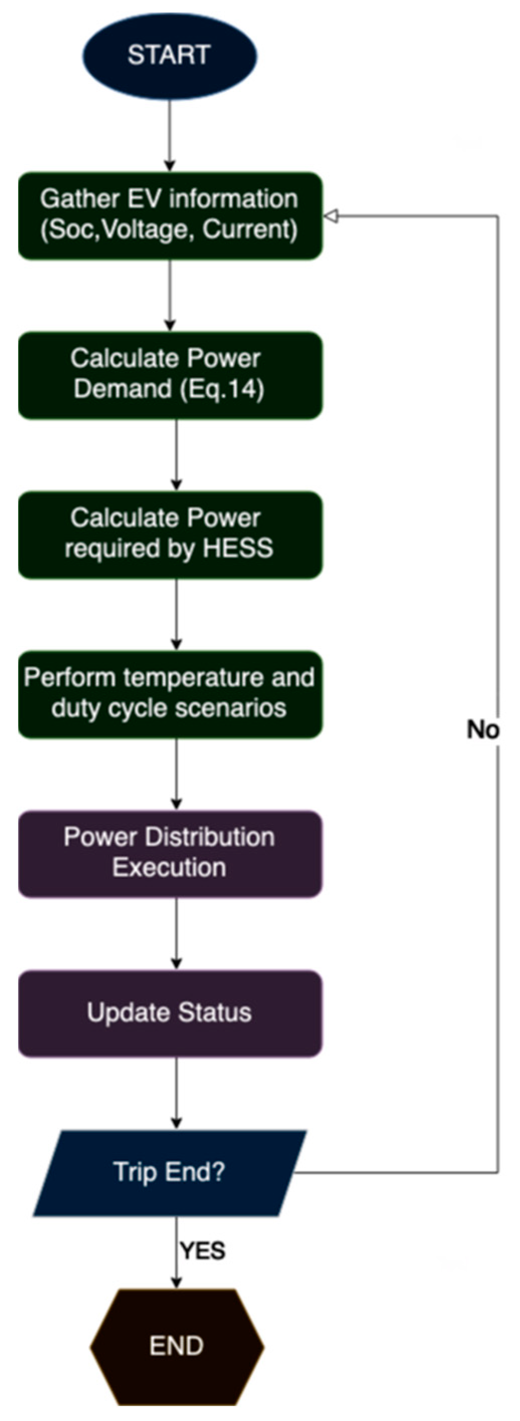
2.1. Methodology
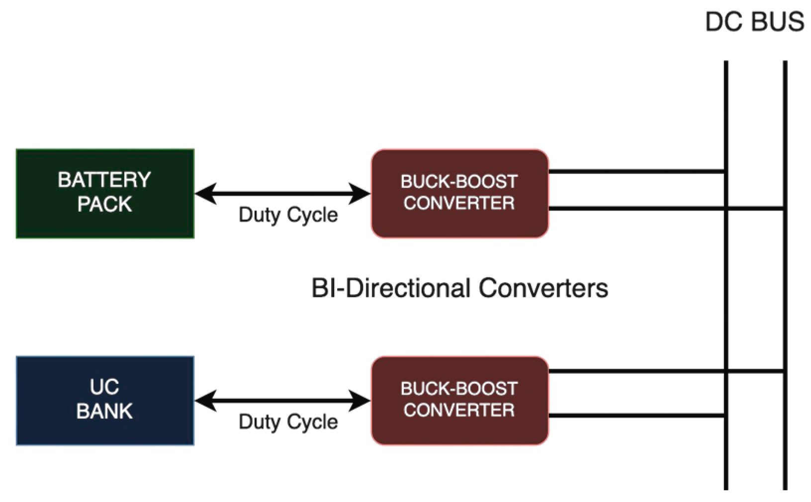
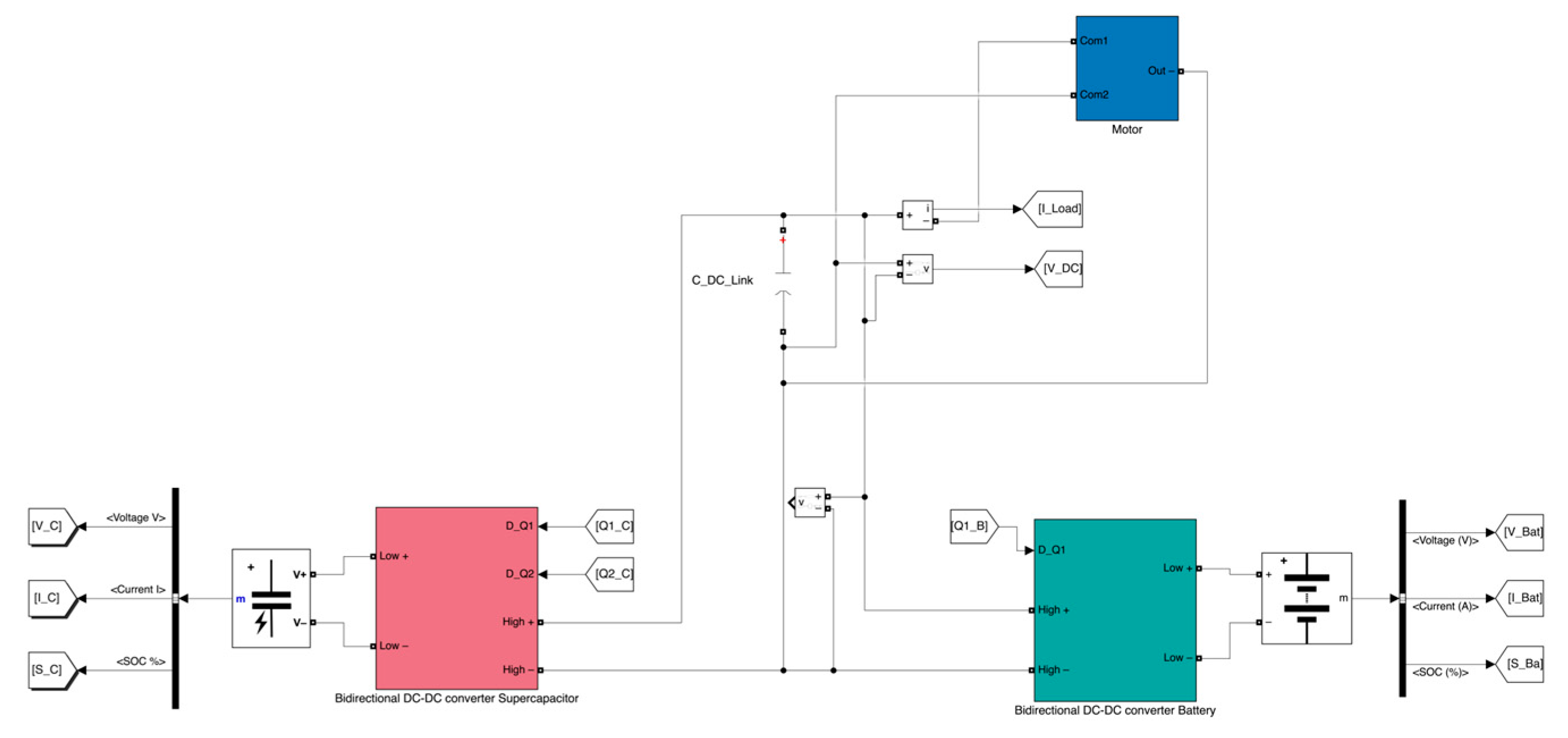
2.1.1. Hybrid Storage System Bank
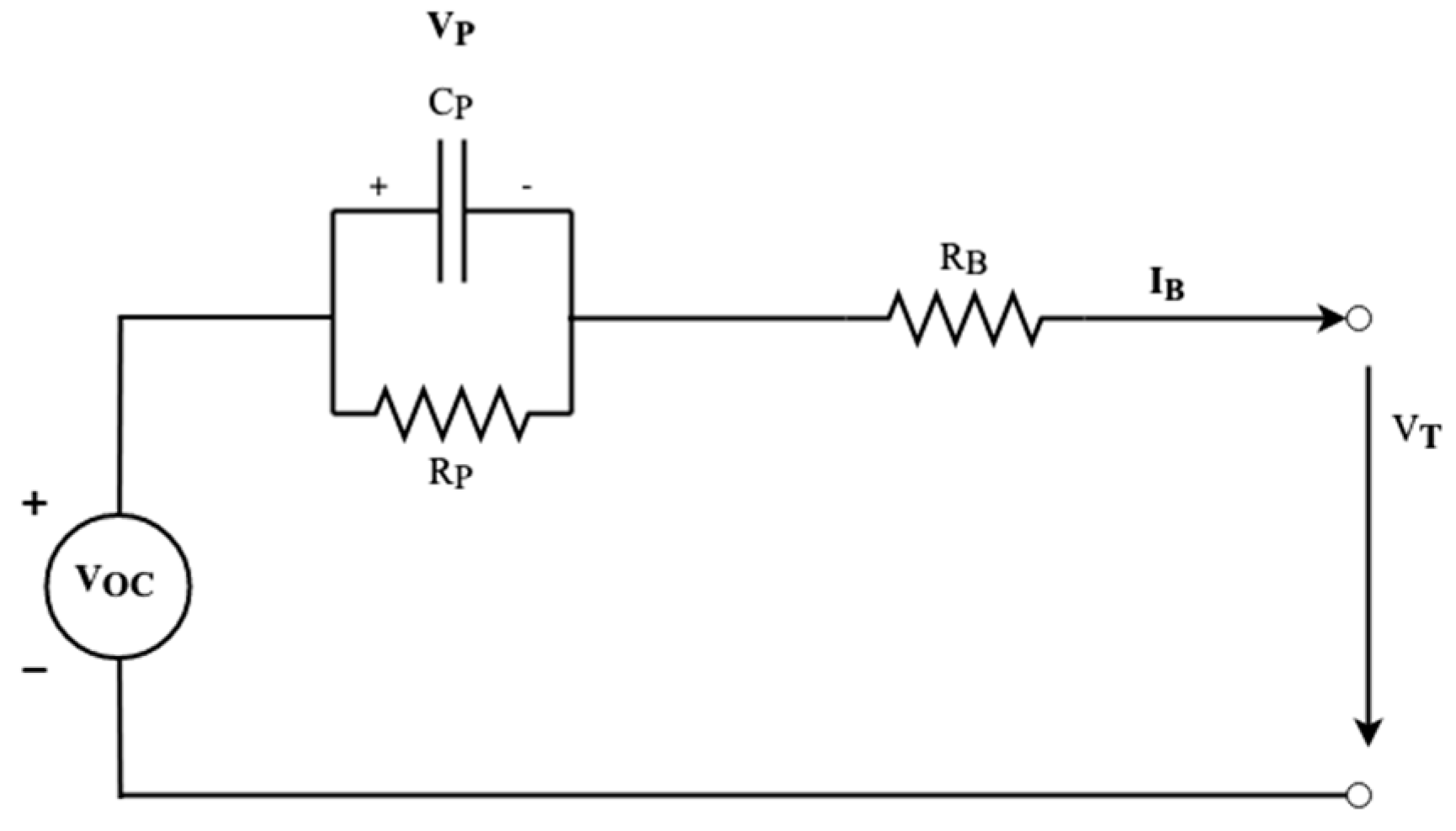
2.1.2. Energy Sources Models
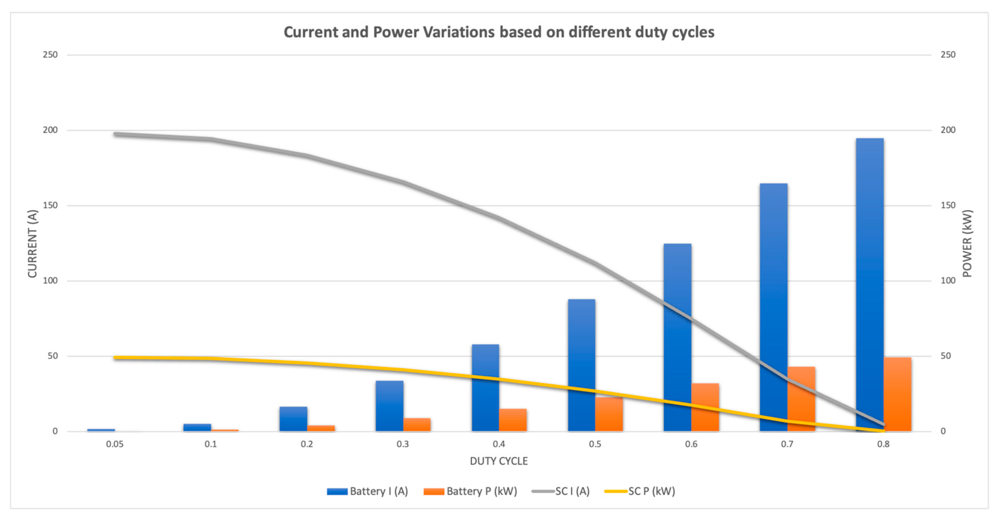
2.1.3. Duty Cycles
2.1.4. Power Modes
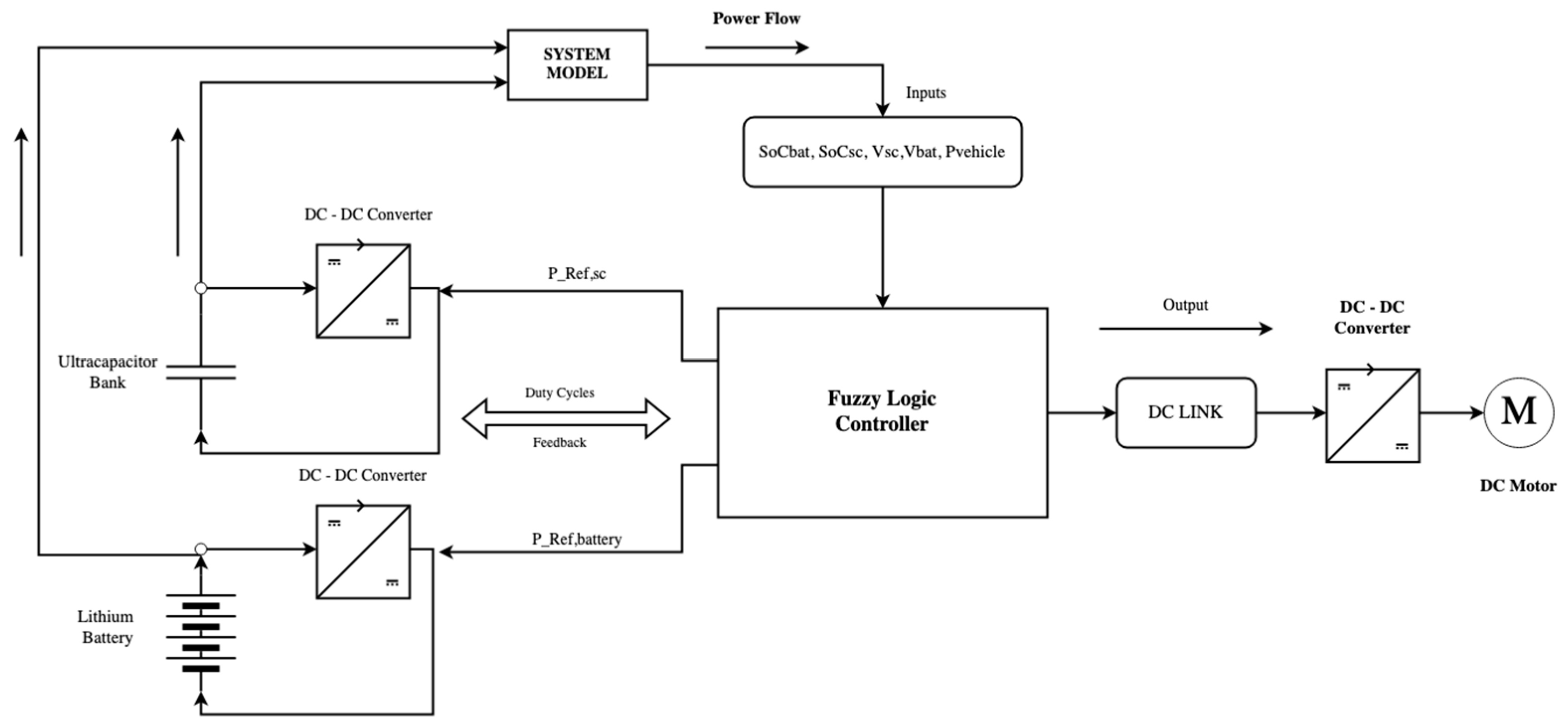
2.2. Fuzzy Model
- Voltage regulation of the DC bus during load variations;
- Limited battery current and frequency fluctuations hence lower temperatures;
- High performance, simplicity, reliability, and enhanced lifetime;
- The linearity pattern of data acquisition is a crucial parameter for a fuzzy model. A weighted memory H controller is utilized at [30] for increased precision in non-linear monitoring and identification of memory states based on Takagi-Sugeno fuzzy systems. The Wavelet packet decomposition method can be utilized for time sequence determination for consistent data retrieval, identification of charging or discharging states, and even power mode classification [31]. In addition, fuzzy logic modeling can be applied not only to EVs but also to smaller applications like electric scooters or three wheelers as well, limiting fluctuations and enhancing range [32].
- The developed fuzzy set-based controller has five inputs: Power demand, UC, and battery voltages, and SoC. The controller uses a list of fuzzy rules to manipulate the correlation between inputs and outputs. According to the principles, efficient energy management must be provided with respect to the operating conditions of the energy source [33]. The supply is based on the SoC of each source and the power modes described before, which may also indicate the driving style [34]. The basic relationship between input and output, as defined by the fuzzy rules, is that the battery acts as the main energy source for the vehicle as long as the SOC is above 25% and the voltage of the ultracapacitor is below 50%.
- At constant speeds with low energy consumption, energy is provided by the lithium battery, while the SC should be saved for peak demand loads like high slopes and rapid accelerations. Additionally, supercapacitors are efficient in regenerative braking exploitation since their high power density allows swift charging, even with high-frequency currents. Afterwards, SC can charge the battery or utilize a low-pass filter for that case to avoid high frequencies. The rules that comprise the fuzzy model are the following [35,36]:
- Power demand and SOCSC are M to H:SC will provide the demand entirely.
- Power demand is H and SOCSC is ML: SC will provide its available power.
- Power demand is M to H and SOCSC is L: Both sources output will be balanced.
- Power demand is L to ML and SOCSC is L: Again, sources are balanced.
- Power demand is ML and SOCSC is L: Battery will cover the power mostly.
- Power demand is L to ML and SOCSC is M to H: SC will provide most of the power.
- 13.
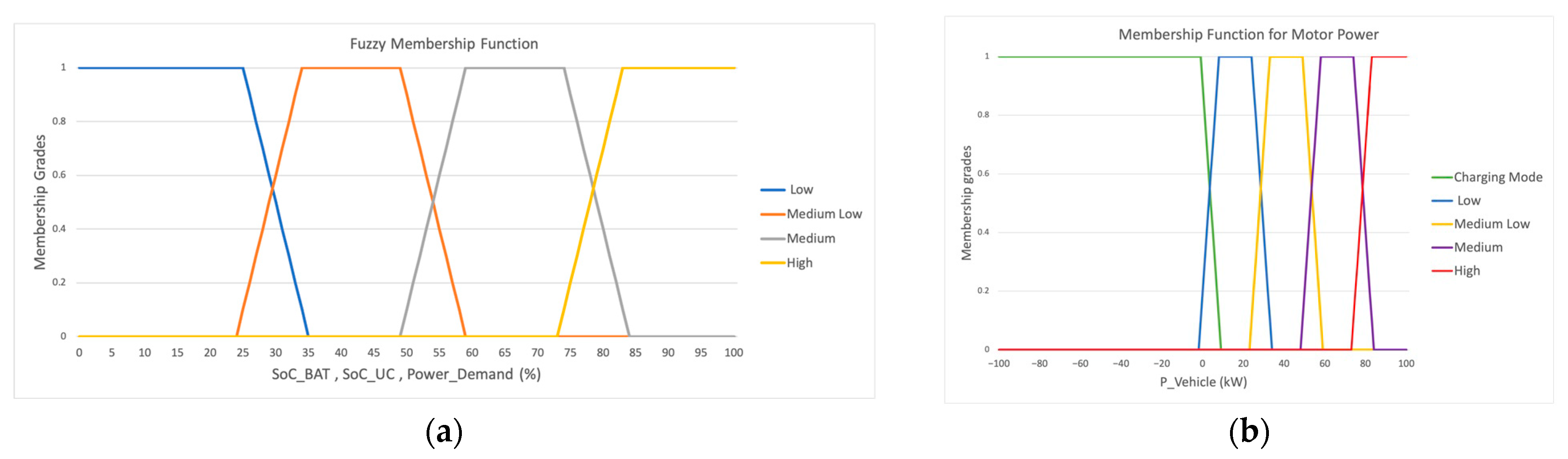
- Low: 0–25%
- 14.
- Medium Low: 25–50%
- 15.
- Medium: 50–75%
- 16.
- High: >75%
3. Results and Discussion
3.1. HESS Power Variations under Different Duty Cycles
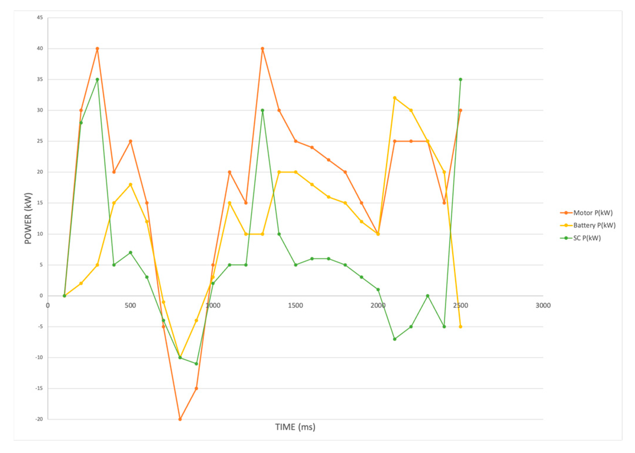
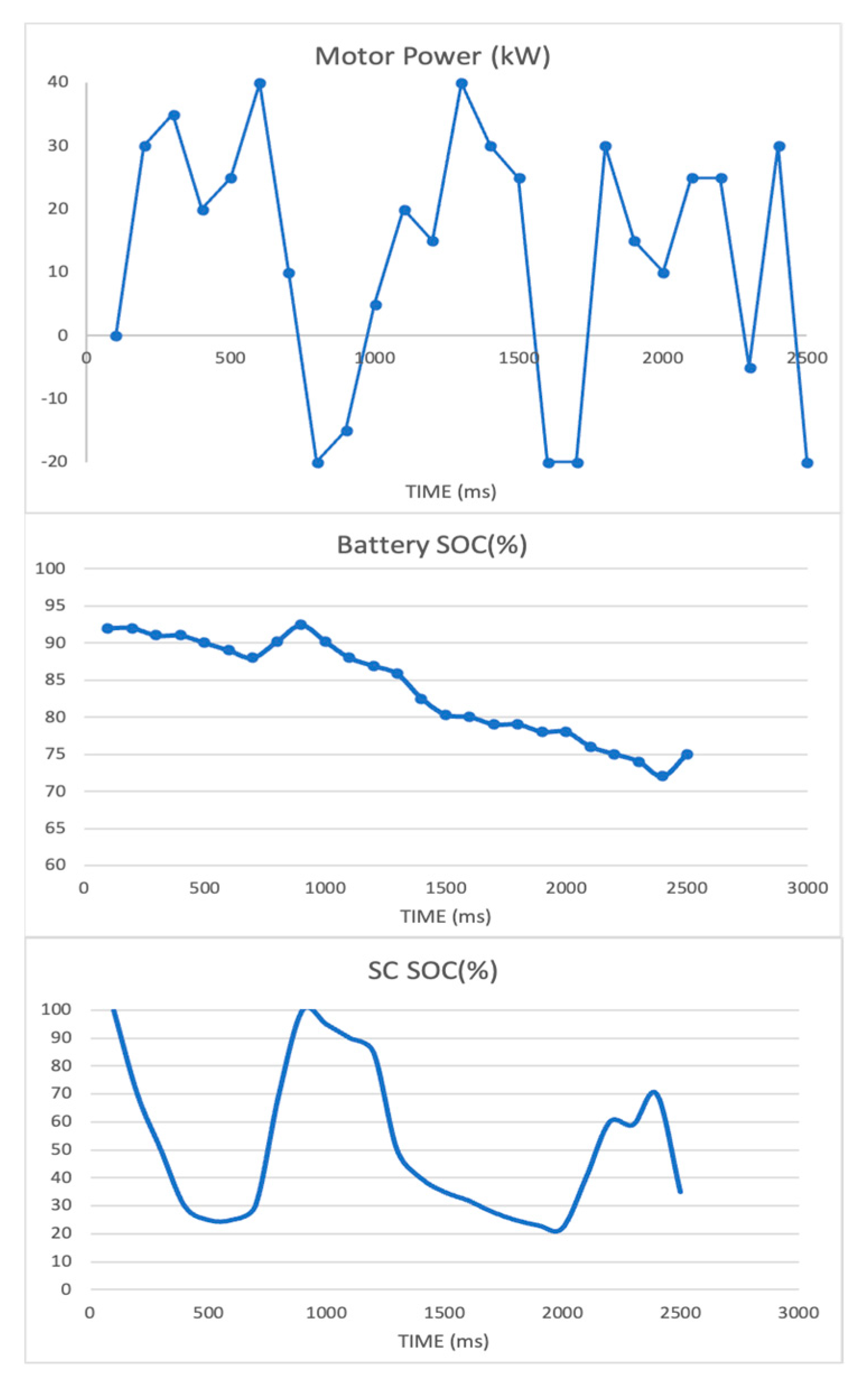
3.2. Power Distribution of HESS Depending on Total Demand
4. Conclusions
Author Contributions
Funding
Data Availability Statement
Conflicts of Interest
Abbreviations
| PVEHICLE | Power demand of the Vehicle |
| VH | Buck Boost converter high voltage side |
| IUC | Ultracapacitor current |
| VL | Buck-Boost converter high voltage side |
| IB | Battery Current |
| PCON,LOSS | Buck-Boost converter power losses |
| DBOOST | Duty cycle on the boost mode |
| DBUCK | Duty cycle on the buck mode |
| VS | Voltage drop on the converter switch |
| VD | Voltage drop on the converter diode |
| RS | Resistance on the converter switch |
| RL | Inductor resistance of the converter |
| RD | Resistance on the converter diode |
| VP | Battery polarization voltage |
| RP | Battery polarization resistance |
| RB | Battery internal resistance |
| CP | Battery polarization capacitance |
| VOC | Open circuit voltage |
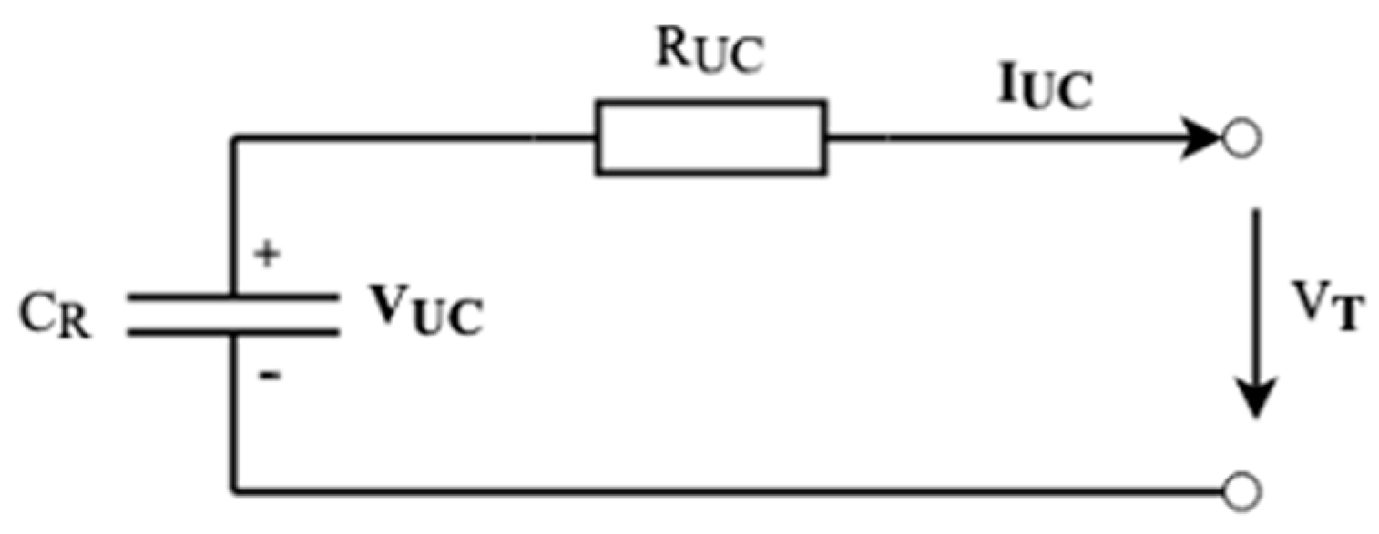
| VT | Terminal voltage |
| k | Time interval for the battery pack |
| PB,LOSS | Battery power losses |
| RUC | Ultracapacitor internal resistance |
| IUC | Ultracapacitor current |
| CR | Ultracapacitor rated capacitance |
| n | Time interval for the ultracapacitor bank |
| PUC | Ultracapacitor power |
| PUC,LOSS | Ultracapacitor power losses |
| VRATED | Rated voltage by the manufacturer |
| PLOSS,TOTAL | Total power losses |
| η | Powertrain efficiency |
| M | Vehicle mass |
| g | Gravitational acceleration |
| f | Rolling assistance coefficient |
| β | Road incline |
| CARC | Air assistance coefficient |
| A | Wind exposed area of the vehicle |
| VA | Vehicle speed |
| δ | Road mass coefficient correction factor |
| UR | Battery rated voltage |
| CR | Battery rated voltage |
| nP | Battery cells in parallel |
| nS | Battery cells in series |
| SoC | State of Charge |
| SoH | State of Health |
References
- Climate Action and the Green Deal. Available online: https://commission.europa.eu/strategy-and-policy/priorities-2019-2024/european-green-deal/climate-action-and-green-deal_en (accessed on 18 August 2023).
- Tsemekidi Tzeiranaki, S.; Economidou, M.; Bertoldi, P.; Thiel, C.; Fontaras, G.; Clementi, E.L.; Franco De Los Rios, C. The Impact of Energy Efficiency and Decarbonisation Policies on the European Road Transport Sector. Transp. Res. Part A Policy Pract. 2023, 170, 103623. [Google Scholar] [CrossRef]
- Komnos, D.; Tsiakmakis, S.; Pavlovic, J.; Ntziachristos, L.; Fontaras, G. Analysing the Real-World Fuel and Energy Consumption of Conventional and Electric Cars in Europe. Energy Convers. Manag. 2022, 270, 116161. [Google Scholar] [CrossRef]
- Tansini, A.; Fontaras, G.; Millo, F. A Multipurpose Simulation Approach for Hybrid Electric Vehicles to Support the European CO2 Emissions Framework. Atmosphere 2023, 14, 587. [Google Scholar] [CrossRef]
- Rimpas, D.; Kaminaris, S.D.; Aldarraji, I.; Piromalis, D.; Vokas, G.; Papageorgas, P.G.; Tsaramirsis, G. Energy Management and Storage Systems on Electric Vehicles: A Comprehensive Review. Mater. Today Proc. 2022, 61, 813–819. [Google Scholar] [CrossRef]
- Electric Vehicles. Available online: https://www.iea.org/energy-system/transport/electric-vehicles (accessed on 18 August 2023).
- Hartani, M.A.; Hamouda, M.; Abdelkhalek, O.; Mekhilef, S. Sustainable Energy Assessment of Multi-Type Energy Storage System in Direct-Current-Microgrids Adopting Mamdani with Sugeno Fuzzy Logic-Based Energy Management Strategy. J. Energy Storage 2022, 56, 106037. [Google Scholar] [CrossRef]
- Zhao, Y.; Dan, D.; Zheng, S.; Wei, M.; Xie, Y. A Two-Stage Eco-Cooling Control Strategy for Electric Vehicle Thermal Management System Considering Multi-Source Information Fusion. Energy 2023, 267, 126606. [Google Scholar] [CrossRef]
- Tran, M.-K.; Panchal, S.; Khang, T.D.; Panchal, K.; Fraser, R.; Fowler, M. Concept Review of a Cloud-Based Smart Battery Management System for Lithium-Ion Batteries: Feasibility, Logistics, and Functionality. Batteries 2022, 8, 19. [Google Scholar] [CrossRef] [PubMed]
- Lai, X.; Yuan, M.; Tang, X.; Yao, Y.; Weng, J.; Gao, F.; Ma, W.; Zheng, Y. Co-Estimation of State-of-Charge and State-of-Health for Lithium-Ion Batteries Considering Temperature and Ageing. Energies 2022, 15, 7416. [Google Scholar] [CrossRef]
- Chen, H.; Xiong, R.; Lin, C.; Shen, W. Model Predictive Control Based Real-Time Energy Management for a Hybrid Energy Storage System. CSEE J. Power Energy Syst. 2020, 7, 862–874. [Google Scholar] [CrossRef]
- Liu, K.; Kang, L.; Xie, D. Online State of Health Estimation of Lithium-Ion Batteries Based on Charging Process and Long Short-Term Memory Recurrent Neural Network. Batteries 2023, 9, 94. [Google Scholar] [CrossRef]
- Wang, Y.; Gao, G.; Li, X.; Chen, Z. A Fractional-Order Model-Based State Estimation Approach for Lithium-Ion Battery and Ultra-Capacitor Hybrid Power Source System Considering Load Trajectory. J. Power Sources 2020, 449, 227543. [Google Scholar] [CrossRef]
- Lemian, D.; Bode, F. Battery-Supercapacitor Energy Storage Systems for Electrical Vehicles: A Review. Energies 2022, 15, 5683. [Google Scholar] [CrossRef]
- Einan, M.; Torkaman, H.; Pourgholi, M. Optimized Fuzzy-Cuckoo Controller for Active Power Control of Battery Energy Storage System, Photovoltaic, Fuel Cell and Wind Turbine in an Isolated Micro-Grid. Batteries 2017, 3, 23. [Google Scholar] [CrossRef]
- Zhang, Q.; Li, G. Experimental Study on a Semi-Active Battery-Supercapacitor Hybrid Energy Storage System for Electric Vehicle Application. IEEE Trans. Power Electron. 2020, 35, 1014–1021. [Google Scholar] [CrossRef]
- Bhurse, S.S.; Bhole, A.A. A Review of Regenerative Braking in Electric Vehicles. In Proceedings of the 2018 International Conference on Computation of Power, Energy, Information and Communication (ICCPEIC), Chennai, India, 28–29 March 2018; pp. 363–367. [Google Scholar]
- Pipicelli, M.; Sessa, B.; De Nola, F.; Gimelli, A.; Di Blasio, G. Assessment of Battery–Supercapacitor Topologies of an Electric Vehicle under Real Driving Conditions. Vehicles 2023, 5, 424–445. [Google Scholar] [CrossRef]
- Chmielewski, A.; Piórkowski, P.; Bogdziński, K.; Możaryn, J. Application of a Bidirectional DC/DC Converter to Control the Power Distribution in the Battery–Ultracapacitor System. Energies 2023, 16, 3687. [Google Scholar] [CrossRef]
- Lin, H.; Jiang, J.; Wei, S.; Cheng, L. Optimization Control for the Efficiency of an On-Board Hybrid Energy Storage System in Tramway Based on Fuzzy Control. In Proceedings of the 2017 11th IEEE International Conference on Compatibility, Power Electronics and Power Engineering (CPE-POWERENG), Cadiz, Spain, 4–6 April 2017; pp. 454–459. [Google Scholar]
- Dong, A.; Ma, R.; Deng, Y. Optimization on Charging of the Direct Hybrid Lithium-Ion Battery and Supercapacitor for High Power Application through Resistance Balancing. Energy 2023, 273, 127233. [Google Scholar] [CrossRef]
- Ghoulam, Y.; Pavot, T.; Mamouri, L.; Mesbahi, T.; Durand, S.; Lallement, C.; Kiefer, R.; Laroche, E. Energy Management Strategy with Adaptive Cut-off Frequency for Hybrid Energy Storage System in Electric Vehicles. In Proceedings of the 2022 IEEE Vehicle Power and Propulsion Conference (VPPC), Merced, CA, USA, 1–4 November 2022; pp. 1–6. [Google Scholar]
- Xiong, R.; Duan, Y.; Cao, J.; Yu, Q. Battery and Ultracapacitor In-the-Loop Approach to Validate a Real-Time Power Management Method for an All-Climate Electric Vehicle. Appl. Energy 2018, 217, 153–165. [Google Scholar] [CrossRef]
- Xu, W.; Liu, M.; Xu, L.; Zhang, S. Energy Management Strategy of Hydrogen Fuel Cell/Battery/Ultracapacitor Hybrid Tractor Based on Efficiency Optimization. Appl. Sci. 2023, 13, 151. [Google Scholar] [CrossRef]
- Pai, F.S. Design and Control Method of a Battery/Ultra-Capacitor Energy Storage System for EVs. Int. J. Electr. Electron. Eng. Telecommun. 2023, 12, 203–208. [Google Scholar] [CrossRef]
- Feng, N.; Ma, T.; Chen, C. Fuzzy Energy Management Strategy for Hybrid Electric Vehicles on Battery State-of-Charge Estimation by Particle Filter. SN Appl. Sci. 2022, 4, 256. [Google Scholar] [CrossRef]
- Wang, C.; Liu, R.; Tang, A. Energy Management Strategy of Hybrid Energy Storage System for Electric Vehicles Based on Genetic Algorithm Optimization and Temperature Effect. J. Energy Storage 2022, 51, 104314. [Google Scholar] [CrossRef]
- Podder, A.K.; Chakraborty, O.; Islam, S.; Manoj Kumar, N.; Alhelou, H.H. Control Strategies of Different Hybrid Energy Storage Systems for Electric Vehicles Applications. IEEE Access 2021, 9, 51865–51895. [Google Scholar] [CrossRef]
- Hussain, S.; Ali, M.U.; Park, G.-S.; Nengroo, S.H.; Khan, M.A.; Kim, H.-J. A Real-Time Bi-Adaptive Controller-Based Energy Management System for Battery–Supercapacitor Hybrid Electric Vehicles. Energies 2019, 12, 4662. [Google Scholar] [CrossRef]
- Yan, S.; Gu, Z.; Ding, L.; Park, J.H.; Xie, X. Weighted Memory H∞ Stabilization of Time-Varying Delayed Takagi-Sugeno Fuzzy Systems. IEEE Trans. Fuzzy Syst. 2023, 1–6. [Google Scholar] [CrossRef]
- Zhao, X.; Zhang, Y.; Cui, X.; Wan, L.; Qiu, J.; Shang, E.; Zhang, Y.; Zhao, H. Wavelet Packet-Fuzzy Optimization Control Strategy of Hybrid Energy Storage Considering Charge–Discharge Time Sequence. Sustainability 2023, 15, 10412. [Google Scholar] [CrossRef]
- Boumediene, S.; Nasri, A.; Hamza, T.; Hicham, C.; Kayisli, K.; Garg, H. Fuzzy Logic-Based Energy Management System (EMS) of Hybrid Power Sources: Battery/Super Capacitor for Electric Scooter Supply. J. Eng. Res. 2023, S2307187723001682. [Google Scholar] [CrossRef]
- Rocha, S.P.D.; Silva, S.M.D.; Ekel, P.I. Fuzzy Set-Based Approach for Grid Integration and Operation of Ultra-Fast Charging Electric Buses. Int. J. Electr. Power Energy Syst. 2022, 138, 107919. [Google Scholar] [CrossRef]
- Shelma, G.; Rajeev, T. Fuzzy-Based Control Strategy for Supercapacitor Assisted Battery Powered EV. In Proceedings of the 2023 International Conference on Control, Communication and Computing (ICCC), Thiruvananthapuram, India, 19–21 May 2023; pp. 1–6. [Google Scholar]
- Angundjaja, C.Y.; Wang, Y.; Jiang, W. Power Management for Connected EVs Using a Fuzzy Logic Controller and Artificial Neural Network. Appl. Sci. 2022, 12, 52. [Google Scholar] [CrossRef]
- Van Jaarsveld, M.J.; Gouws, R. An Active Hybrid Energy Storage System Utilising a Fuzzy Logic Rule-Based Control Strategy. World Electr. Veh. J. 2020, 11, 34. [Google Scholar] [CrossRef]
- Khan, M.A.; Zeb, K.; Sathishkumar, P.; Ali, M.U.; Uddin, W.; Hussain, S.; Ishfaq, M.; Khan, I.; Cho, H.-G.; Kim, H.-J. A Novel Supercapacitor/Lithium-Ion Hybrid Energy System with a Fuzzy Logic-Controlled Fast Charging and Intelligent Energy Management System. Electronics 2018, 7, 63. [Google Scholar] [CrossRef]
- Zakzouk, N.E.; Lotfi, R.A. Power Flow Control of a Hybrid Battery/Supercapacitor Standalone PV System under Irradiance and Load Variations. In Proceedings of the 2020 10th International Conference on Power and Energy Systems (ICPES), Chengdu, China, 25–27 December 2020; pp. 469–474. [Google Scholar]
- Rimpas, D.; Kaminaris, S.D.; Piromalis, D.; Vokas, G.; Papageorgas, P. Design and Implementation of a Small-Scaled Hybrid Storage System for Optimal Sizing in Electric Vehicles; AIP Publishing: Metz, France, 2023; p. 020007. [Google Scholar]
- Sheikh, S.S.; Anjum, M.; Khan, M.A.; Hassan, S.A.; Khalid, H.A.; Gastli, A.; Ben-Brahim, L. A Battery Health Monitoring Method Using Machine Learning: A Data-Driven Approach. Energies 2020, 13, 3658. [Google Scholar] [CrossRef]

| Power State | Power Output | |
|---|---|---|
| SC | Battery | |
| Regenerative braking | Charging * | Charging * |
| Coasting | Charging | Charging |
| Initialization | Maximum | Low |
| Slow Acceleration | Medium | Medium |
| Fast Acceleration | High | Medium |
| Time (ms) | PVEHICLE (kW) | SoCBAT (%) | SoCUC (%) |
|---|---|---|---|
| 100 | 0 | 92 | 100 |
| 200 | 30 | 92 | 70 |
| 300 | 35 | 91 | 50 |
| 400 | 20 | 91 | 30 |
| 500 | 25 | 90 | 25 |
| 600 | 40 | 89 | 25 |
| 700 | 10 | 88 | 30 |
| 800 | −20 | 90.2 | 70 |
| 900 | −15 | 92.4 | 100 |
| 1000 | 5 | 90.2 | 95 |
| 1100 | 20 | 88 | 90 |
| 1200 | 15 | 86.9 | 85 |
| 1300 | 40 | 85.8 | 50 |
| 1400 | 30 | 82.5 | 40 |
| 1500 | 25 | 80.3 | 35 |
| 1600 | −20 | 80 | 32 |
| 1700 | −20 | 79 | 28 |
| 1800 | 30 | 79 | 25 |
| 1900 | 15 | 78 | 23 |
| 2000 | 10 | 78 | 22 |
| 2100 | 25 | 76 | 40 |
| 2200 | 25 | 75 | 60 |
| 2300 | −5 | 74 | 59 |
| 2400 | −30 | 72 | 70 |
| 2500 | −20 | 75 | 35 |
| A/A | Paper | Layout | Outcome |
|---|---|---|---|
| 1 | [7] | Sustainable Fuzzy Model | Power distribution through duty cycles, Utilization for lower battery stress |
| 2 | [8] | Fuzzy PID Controller | Smaller battery aging |
| 3 | [11] | Model Predictive Control | Lower battery current fluctuations, SOV indication, Single power mode |
| 4 | [13] | Fractional Order Modelling | Optimized SoC and HESS discharge time calculation |
| 5 | [19] | Semi-Active Topology | Smooth distribution for 2.5 C operation rates |
| 6 | [20] | Optimization Control for Trams | Power mode differentiation utilize better efficiency and safe operation |
| 7 | [21] | Fine tuning resistance and duty cycle method | Safe HESS Operation, battery life prolonging but higher charging time |
| 8 | [23] | Rule based Strategy with CanBUS | Power modes approach minimize Battery current and high UC employment |
| 9 | [24] | Multi-Layer Strategy on HESS | 20–80% SoC indication for safe operation Single power mode |
| 10 | [25] | Buck-Boost Converter modelling | Two power modes implementation for lower operational temperature |
| 11 | [26] | Particle Filter | Accurate state of charge calculation, with power mode introduction |
| 12 | [27] | Genetic Algorithm Optimization | Better efficiency at higher temperatures, no power modes |
| 13 | [29] | Semi-Active adaptive controller | High recovery through regenerating braking at all drive states |
| 14 | [33] | Fuzzy logic controller for electric bus | UC exploitation as primary source for better sizing, no power modes |
| 15 | [35] | Fuzzy Logic Control Optimization | Power demand-based distribution achieving 50% lower fluctuations |
| 16 | [36] | Fuzzy Logic rule-based Strategy | Duty cycle and sources SoC Consideration for better control |
| 17 | This paper | Fuzzy Logic Rule-Based Strategy | Duty cycle and power modes connection for optimized power distribution within safe Source operational range |
Disclaimer/Publisher’s Note: The statements, opinions and data contained in all publications are solely those of the individual author(s) and contributor(s) and not of MDPI and/or the editor(s). MDPI and/or the editor(s) disclaim responsibility for any injury to people or property resulting from any ideas, methods, instructions or products referred to in the content. |
© 2023 by the authors. Licensee MDPI, Basel, Switzerland. This article is an open access article distributed under the terms and conditions of the Creative Commons Attribution (CC BY) license (https://creativecommons.org/licenses/by/4.0/).
Share and Cite
Rimpas, D.; Kaminaris, S.D.; Piromalis, D.D.; Vokas, G. Real-Time Management for an EV Hybrid Storage System Based on Fuzzy Control. Mathematics 2023, 11, 4429. https://doi.org/10.3390/math11214429
Rimpas D, Kaminaris SD, Piromalis DD, Vokas G. Real-Time Management for an EV Hybrid Storage System Based on Fuzzy Control. Mathematics. 2023; 11(21):4429. https://doi.org/10.3390/math11214429
Chicago/Turabian StyleRimpas, Dimitrios, Stavrοs D. Kaminaris, Dimitrios D. Piromalis, and George Vokas. 2023. "Real-Time Management for an EV Hybrid Storage System Based on Fuzzy Control" Mathematics 11, no. 21: 4429. https://doi.org/10.3390/math11214429
APA StyleRimpas, D., Kaminaris, S. D., Piromalis, D. D., & Vokas, G. (2023). Real-Time Management for an EV Hybrid Storage System Based on Fuzzy Control. Mathematics, 11(21), 4429. https://doi.org/10.3390/math11214429