Article

PIDFusion: Fusing Dense LiDAR Points and Camera Images at Pixel-Instance Level for 3D Object Detection

School of Information Science and Technology, North China University of Technology, Beijing 100144, China
*
Author to whom correspondence should be addressed.
Mathematics 2023, 11(20), 4277; https://doi.org/10.3390/math11204277
Submission received: 29 August 2023 / Revised: 7 October 2023 / Accepted: 9 October 2023 / Published: 13 October 2023

Abstract

:
In driverless systems (scenarios such as subways, buses, trucks, etc.), multi-modal data fusion, such as light detection and ranging (LiDAR) points and camera images, is essential for accurate 3D object detection. In the fusion process, the information interaction between the modes is challenging due to the different coordinate systems of various sensors and the significant difference in the density of the collected data. It is necessary to fully consider the consistency and complementarity of multi-modal information, make up for the gap between multi-source data density, and achieve the joint interactive processing of multi-source information. Therefore, this paper is based on Transformer to improve a new multi-modal fusion model called PIDFusion for 3D object detection. Firstly, the method uses the results of 2D instance segmentation to generate dense 3D virtual points to enhance the original sparse 3D point clouds. This optimizes the issue that the nearest Euclidean distance in the 2D image space cannot ensure the nearest in the 3D space. Secondly, a new cross-modal fusion architecture is designed to maintain individual per-modality features to take advantage of their unique characteristics during 3D object detection. Finally, an instance-level fusion module is proposed to enhance semantic consistency through cross-modal feature interaction. Experiments show that PIDFusion is far ahead of existing 3D object detection methods, especially for small and long-range objects, with 70.8 mAP and 73.5 NDS on the nuScenes test set.

1. Introduction

In the autonomous driving scenario (for example, subways, buses, trucks), it is essential for high-speed vehicles to quickly and accurately perceive the surrounding environmental information, such as the type, size, distance, and direction of the object [1]. Sensors such as LiDAR, RGB (red, green, blue) cameras, and millimeters wave radar are put on the vehicle to collect information about its surroundings. The data collected by each sensor have their unique properties. For instance, the point clouds obtained by LiDAR is a sparse unstructured data set that can preserve the rich original geometric information, but has poor resolution and data processing requires more computer power [2]. The RGB camera can gather more information on the texture, but it is less resistant to bad weather and has poor range and environmental adaptability. As a result, data from a single sensor has inherent flaws that make it challenging to deal with complicated and dynamic driving circumstances. Recently, numerous researchers combined data from various sensors [3], taking full advantage of the benefits of varied data. This multi-modal fusion algorithm performs significantly better than using just one modality. Unfortunately, the structural restrictions of the current fusion techniques may result in losing modal information and weaken the unity of fusion.
Existing multimodal 3D object detection methods usually use projection methods for one-sided interaction to accomplish pixel-level fusion. For instance, category scores or semantic characteristics from images are aggregated into 3D point clouds by PointPainting [4] and its derivatives Pointaugmenting [5], FusionPainting [6], and Multimodal virtual point 3D detection [7]. Due to spatial distortion brought on by the sparsity of point clouds, long-range and small objects will be difficult to identify during the fusion process, leading to missed detection. The typical approach uses a unilateral interaction approach, which biases the fusion feature towards a single mode and results in the loss of a significant amount of modal feature information [8]. While pixel-level feature alignment broadens the scope of the fusion, it uses semantic image data in an unsatisfactory manner.
To solve the above problems, the text proposes a novel multimodal feature fusion framework PIDFusion, which adopts a multi-stage cross-modal information fusion approach for 3D object detection. The multi-modal information is fully utilized and fused, and the effectiveness of the structure is proved in the detection of small objects and occlusion objects. (1) Firstly, the dense 3D virtual points creation module builds on the initial sparse point clouds by creating dense 3D virtual points using a set of 2D segmentation results. This work optimizes the issue that the nearest Euclidean distance in the 2D image space cannot ensure the nearest in the 3D space in the 3D virtual point creation algorithm. (2) Secondly, a novel modal interaction method is proposed to employ the LiDAR points and camera images from the BEV bird’s-eye view (BEV) perspective as multiple inputs for bilateral interaction fusion instead of the primary method of fusing into a single feature representation. To ensure information sharing and to keep the special benefits associated with each mode, the encoder must learn and maintain the features under two distinct operating regimes. (3) Lastly, this paper conducts similarity constraints on paired 3D and 2D proposal boxes to bridge the gap between pixel-level and instance-level fusion to address the issue of rough pixel-level fusion. With the three stages above of the cross-modal information fusion module, PIDFusion obtained results on the nuScenes test set of 71.5 mAP and 74.2 NDS.

2. Related Works

Currently, there are two main types of 3D object detection, the single-modal approach based on 2D images captured by cameras and 3D point clouds based on LiDAR scans, and the cutting-edge multi-sensor fusion approach.

2.1. 3D Object Detection Method Based on Single-Model

Autonomous vehicles are typically fitted with various sensors, including millimeter wave radar, 360° RGB camera, and LiDAR [9]. For a long time, 3D object detection based on data from a single sensor dominated. The two categories of mainstream approaches are point clouds-based and vision-based [10].
Unlike the regular distribution of pixels on an image, point cloud is a sparse and irregular 3D representation [11], which requires the design of a specialized model for feature extraction, and directly applying traditional convolutional networks to point clouds images is not an optimal solution. In point clouds-based 3D target detection methods, according to whether the point clouds is voxelized or not, it can be divided into two categories: point-based processing and voxel-based processing. In 2017, PointNet, proposed by Charles R. Qi et al. [12], was a pioneering work to effectively extract features from point clouds, but he did not take into account the local information, and then the team borrowed the convolutional neural network’s hierarchical structure to propose an upgraded PointNet++ [13], adding a sampling grouping network to categorize the local features of the point clouds.
In addition, another mainstream idea is to divide the point cloud into standard-sized voxels in space, after which the PointNet structure is used several times to extract features, and finally, 3D convolution operation is used to complete the information interaction between sparse voxels [14]. Examples of classic representative works include VoxelNet [3] and PointPillrs [15]. Apple presented Voxelnet in 2017, which clustered and randomly sampled point clouds, but its computing cost was high and real-time detection applications were challenging to implement. To extract 3D voxel features in 2019, SECOND [16] invented the sparse convolutional network. The network architecture was employed in a multitude of research and emerged as the backbone network with the most adoption in voxel-based detectors. Point clouds still have problems extracting detailed semantic data despite having strong spatial information. On the other hand, detection in autonomous driving scenarios usually requires real-time reasoning. As point cloud-based algorithms require a lot of processing, it is not easy to create models that can efficiently handle point clouds data.
A vision-based approach with an innate semantic-awareness advantage [17]. Previous techniques for monocular images tried to predict 3D boxes directly [18,19,20] using graphical features or use intermediate representations [21,22]. It is still far-fetched to utilize a single camera to precisely detect objects in 3D space since it needs to give more 3D information. Autonomous vehicles typically have many cameras to collect accurate environmental data from various angles [23]. One of the main challenges for multi-camera 3D object recognition is recognizing the same thing from multiple photos and combining the object attributes received from various views. Cross-view geometric constraints were suggested as a method for resolving the multi-view object localization problem by Rubino et al. in 2017 [24]. In 2022, DETR3D [25] proposed to convert multi-view features into unified 3D features to deal with the multi-view feature aggregation problem, but due to the loss of 2D image depth information, the 3D geometric information cannot be accurately estimated, and the use of multi-camera fusion does not improve much in detection accuracy. Overall, making full use of multi-sensor information and using the fusion method for feature extraction is the most effective solution.

2.2. 3D Object Detection Method Based on Multi-Modal
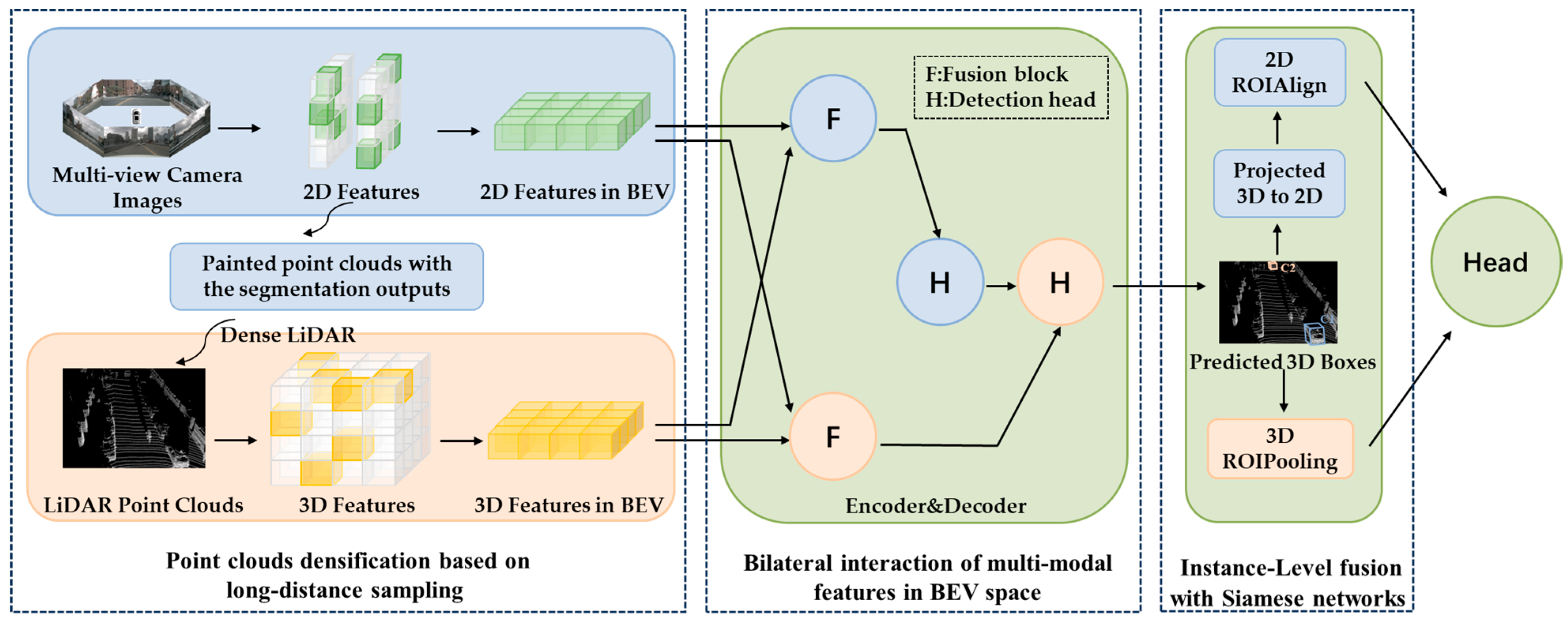
The conversion of multi-modal views into expressions from the perspective of BEV is becoming increasingly common in the present methodologies [26]. On the one hand, it is practical for tasks involving the planning control module that come after. On the other hand, from the viewpoint of the image, objects under BEV have no scaling or occlusion issues. The BEV fusion method has two types of association: hard association and soft association. The processing of two modes separately using calibration matrices for fusion, such as BEVFusion [27], is known as hard association. The approach of constructing pseudo-point clouds by depth estimation, such as LSS [28] and Centernet [29], is where hard association suffers. The created point clouds are not very accurate and involve a lot of calculations, which is rather different from the actual picture. A better solution to this issue is a soft association, a transformer [30] extension that uses one modality (as q) to concentrate on another modality (as k, v) and extract the associated characteristics for fusion, such as Transfusion [31] and DeepInteraction [32]. The two modes’ alignment is the key to the soft association. LiDAR is often used as Q to fuse image features. This not only has the problem of query omission caused by LiDAR feature sparseness, but also has the problem of multiple q mapping to the same object due to LiDAR density.
The main improvement of the hard correlation method is the calibration matrix, and the hardware optimization has a greater enhancement effect than the algorithmic optimization, so there was a proliferation of recent improvements on soft correlation algorithms. To obtain useful semantic data, Chen et al. [33] suggested in 2017 projecting point clouds directly onto images. Geometric distortion results from this method’s disregard for the depth information contained in point clouds. In 2020, Pointpainting [4] invented the method of decorating 3D point clouds with category scores or semantic characteristics in 2D instance segmentation networks. Semantic data are first collected from the image and assigned to the point clouds. The camera pixels are significantly richer than the LiDAR pixels due to the point clouds’ sparseness, which inevitably wastes the image’s 2D features and causes the fusion result to be biased toward single-modal features. Unlike MVP [7], BEVFusion [27] uses each image feature pixel as a seed, and these two exemplary methods address the issue of sparse point clouds. In 2021, Yin et al. [7] suggested choosing pixels from camera foreground objects and projecting them into 3D space for point clouds augmentation. Nevertheless, because of the distance issue, genuine 3D space cannot be recovered when projecting 2D images into 3D space; 4D-Net [34] adopts a unilateral fusion strategy, prefers point clouds data, and does not fully utilize the semantic information of the image. It uses point clouds features to dynamically focus on image features and combines 2D camera images with 3D point clouds data to improve the accuracy of long-distance object recognition. MLF-DET [35] integrates feature-level fusion and decision-level fusion, and uses a multi-layer fusion network to improve the utilization of image information. FBMNet [36] learns the assignments between 3D and 2D object proposals and combines their region of interest (ROI) features for detection fusion. Thus, the fusion method’s current focus is on correlating multi-modality.

3. Method

This section introduces the PIDFusion multi-modal feature fusion framework for 3D object detection. Unlike previous research, PIDFusion is based on a multi-stage fusion architecture consisting of three stages, as shown in Figure 1: the point clouds densification module, the use of 2D image instance segmentation information to increase the number of 3D point clouds, generating dense point clouds; bilateral interaction module, respectively, the image features and point clouds features as Query cross-attention learning, multi-modal information complementary; and the instance-level fusion module, the captured 3D box and the corresponding 2D box similarity constraints, to maximize the similarity between the two.

3.1. Point Clouds Densification Based on Long-Distance Sampling

Multi-modal feature fusion fuses LiDAR and image features into a unified scene for representation. In the process of image feature fusion, there is a problem that the point clouds in 3D space cannot accurately reflect the geometric structure of the target in 3D space. The MVP algorithm selects seeds from the 2D image plane and performs depth estimation to generate dense 3D virtual points and enhance the original sparse 3D point clouds. MVP first performs instance segmentation on the image and then projects the laser points onto the image, so that there will be several laser points on each instance on the image. Then, the pixels in each instance are randomly sampled, and the nearest neighbor association is performed with the pixels projected on the laser point, and the depth of the associated laser point is taken as the depth of the current pixel. Finally, these points are projected back to the laser coordinate system to obtain dense LiDAR points, which are then processed using the popular point clouds processing algorithm.
Although MVP is effective, some randomly generated virtual point clouds will distort and lose the authenticity of the target, resulting in the change in spatial structure of the two-dimensional target in the camera after being converted to three-dimensional space. In order to solve this problem, this paper proposes a point clouds densification method based on long-distance sampling and depth estimation using bilinear interpolation.
The long-distance sampling method can ensure the discreteness of the sampling points and cover the entire instance more evenly. Firstly, the first seed A is sampled, and the second seed B is sampled at the farthest point in the remaining instance region. Any pixel P in the remaining region is randomly selected, and the distance from the point P to the selected seed (A, B) is calculated. The minimum distance from seed A and seed B is taken as the distance from the point P to the selected seed, and the distance from the pixel in the remaining region to the selected seed is calculated. The pixel with the largest distance is selected as seed C. Repeat the steps until sampling N’ points. In order to make the depth estimation of the virtual point more accurate, this paper takes the surrounding K pixels on the projection of the laser point for each seed and takes the real depth and coordinates of the K-associated laser points for bilinear interpolation as the depth of the current seed. As shown in Figure 2, (a) randomly select a point as the first sampling point, i.e., the yellow point. (b) The second sampling point is the furthest point from the first sampling point among all the points, i.e., the red point. (c) Selecting the third sampling point: any point is taken to calculate the distance to the first two sampling points, and the shortest distance is taken after comparing them, and repeated, so that after obtaining the ensemble of distances from each point to the sampled points, the largest distance is selected, i.e., the third sampling point. For example, to determine who is the farthest point from point 1 and point 2, calculate the distance from point 1 to the red point and the yellow point, take the shortest distance, repeat the operation for point 2, and then select the largest distance from the ensemble, that is, the third sampling point.
MVP and PIDFusion use the K-Nearest Neighbor method and the long-distance sampling method for depth estimation, respectively. As shown in Figure 3, the K-Nearest Neighbor method takes the depth of the nearest reference point as the depth of the sampling point, and the long-distance sampling method takes the mean value of the depth of the surrounding N reference points as the depth of the sampling point. Compared with K-Nearest Neighbor method, the long-distance sampling method reduces the accidental error of taking the depth of a single reference point, and PIDFusion can obtain a more reliable depth.

3.2. Bilateral Interaction of Multi-Modal Features in BEV Space

Traditional modal fusion usually aggregates multi-modal inputs into a mixed feature map. Different from the traditional strategy, this paper learns and maintains each modal feature through multi-modal representation interaction within the encoder. The encoder is a multi-input multi-output mode, which takes the features extracted independently from the BEV perspective of the laser radar and camera image trunk as input, and the refined features as output. The encoder consists of three parts: interaction between multiple modalities, as shown in Figure 4, interaction within each modality and feature integration, to maximize the exploration of their complementary strengths and retain their respective advantages.

3.2.1. Feature Interaction between Multimodalities

1.
The image coordinate system C and the point clouds coordinate system P are constructed, respectively. B C and B P represent the image representation and LiDAR representation from the perspective of BEV, respectively. Establish the alignment from IMAGE BEV to LiDAR BEV coordinate system: B C B P . Given a coordinate ( i c , j c ) in IMAGE BEV, use LSS [28] to find the pixel coordinates x c , y c , z c in the corresponding image. Then, according to the camera and LiDAR’s internal and external reference matrices, the corresponding relationship between the pixel coordinate system x c , y c , z c and the LiDAR coordinate system x p , y p , z p is found. The Z-axis compressed by the LiDAR coordinate system is the LiDAR BEV coordinate system. Then, find i p , j p in LiDAR BEV to complete the mapping between the IMAGE BEV representation and the LiDAR BEV representation and the corresponding relationship B P C i p , j p = i c , j c . Similarly, from LiDAR BEV to Ithe MAGE BEV coordinate system B p B c , a coordinate i p , j p in LiDAR BEV is given, and the pixel coordinates x p , y p , z p of the corresponding position in the point clouds are found. The pixel coordinates x c , y c , z c in the picture are obtained by the coordinate matrix and then projected to IMAGE BEV. The corresponding relationship is B C P i c , j c = i p , j p .
2.
The interaction process from camera images to point clouds: A feature point of IMAGE BEV is used as Q = g C i c , j c , and the cross-modal feature N P = g P B C P i c , j c is used as K and V for cross-attention learning; g i , j denotes indexing the element at location i , j on the 2D representation g. This is image-to-LiDAR representational interaction.
F ϕ C P g C , g P i , j = K , V ϵ N P s o f t max Q K d V
Given the LiDAR BEV feature point as the query Q = g P i p , j p , do the above, which is the point clouds-to-image interaction.

3.2.2. Feature Interaction within a Single Modality

To fully fuse features, feature interactions within separate modalities are needed for complementary multimodal interactions. The same local attention as defined in Equation (1) is consistently applied. In any of the modes alone, we use the n × n grid neighborhood as the key and value. For a feature point as query, q = g i , j . Formally, we denote F ϕ C C g C = K , V ϵ N C s o f t max Q K d V for image representation and F ϕ P P g P = K , V ϵ N P s o f t max Q K d V for LiDAR representation.

3.2.3. Feature integration

Integrating the results of multimodal feature interactions and unimodal feature interactions, the encoder outputs two integrated features. g C P C is the point cloud-to-image interaction feature, g C C P is the image-to-point cloud interaction feature, g C C C and g P P P are the interaction features within a single modality of the image and point cloud, respectively, (FFN refers to feed-forward network and Concat denotes elements in series).
g C = F F N c o n c a t F F N c o n c a t g C P C , g C C C , g C ,
g P = F F N c o n c a t F F N c o n c a t g P C P , g P P P , g P .

3.3. Instance-Level Fusion with Siamese Networks

Although the pixel-level fusion process preserves the object’s integrity, the object’s pixel-level projection ignores global information, which results in semantic information loss and coarse feature aggregation. This study suggests an instance-level fusion module to capture semantic information to address the issues above, as shown in Figure 5. Several 3D boxes obtained in the previous step are randomly selected, and then projected onto the 2D BEV feature map according to the camera matrix to obtain the corresponding 2D boxes. The paired detection boxes use the cross mode for similarity constraints. ROI pooling and ROI align to aggregate RoI-specific features were performed, respectively, to obtain F i 3 D and F i 2 D with higher detection accuracy. The encoder network f consists of a backbone and a projection MLP head. To maximize the similarity of the two modal features, the features from the image branch and the voxelization feature from the point branch are sent to the encoder f to obtain V 1 = f F i 3 D and V 2 = f F i 2 D , the network structure is the same, and the weights are shared. One side applies M L P h p r e d i c t o r   h , convert f F i 3 D to W 1 = h f F i 3 D , and the other applies the stop-gradient (stopgrad) operation to maximize the similarity between the two, and we minimize their negative cosine similarity:
D W 1 , V 2 = W 1 W 1 2 V 2 V 2 2 .
Stopgrad operation is an important component, and the Formula (4) is modified as D W 1 , s t o p g r a d V 2 . In order to minimize the loss value of the two modal fusion representations, the loss function is:
L I L = 1 2 D W 1 , s t o p g r a d V 2 + 1 2 D W 2 , s t o p g r a d V 1 .
According to DETR [37], find bipartite graph matching between predicted and real targets by the Hungarian algorithm [38]. The loss has three parts: classification, regression and IoU, and the total loss L, designed as:
L = λ 1 L c l s ( p , p ^ ) + λ 2 L r e g ( b , b ^ ) + λ 3 L i o u ( b , b ^ ) + λ 4 L I L .
In the formula: λ 1 , λ 2 , λ 3 are the coefficients of a single loss, L c l s is the binary cross entropy loss, L r e g is the loss of the projection BEV center and the ground real center, and L i o u is the IoU loss between the prediction box and the real box.

4. Experiment

4.1. Dataset Introduction

The complete nuScenes dataset [39] contains all 1000 scenes, 700 for training, 150 for validation, and 150 for testing. The sensor suite includes six cameras, one LiDAR, five radars, GPS, and IMU. The entire dataset contains about 1.4 million camera images, 390,000 LiDAR scans, 1.4 million millimeters-wave radar scans, and 1.4 million object bounding boxes in 40,000 key frames, and is divided into 10 categories: car, truck, bus, trailer, construction vehicle, pedestrian, motorcycle, bicycle, barrier, and traffic cone.

4.2. Implementation Details

The implementation of this paper is based on the mmdetection3d code library. To verify the validity of the structure, we selected PointPillars and SECOND as the representative methods of our experiment. Our model uses a set of 3D sparse convolution blocks [40]; we set the voxel size to (0.075 m, 0.075 m, and 0.2 m). The X and Y-axis detection distance is [−51.2 m, 51.2 m], and the Z-axis detection distance is [−5 m, 3 m]. The maximum number of non-empty voxels for training and inference is set to 120,000 and 160,000, respectively. Following MVP, we select 50 seeds on each instance unless otherwise specified. For the image branch, Faster RCNN [41] with ResNet50 [42] is used as the 2D detector, and the hidden units of the cross-attention alignment module are set to 128. Global features are extracted from a given image, and the weights are frozen during training. Following MVP [7], we select 50 seeds on each instance unless otherwise specified. The output sizes of 2DRoIAlign and 3DRoIPooling are both set to 4. Our LiDAR-only baseline is trained for 20 epochs and LiDAR-image fusion for 6 epochs.
In terms of the data enhancement strategy, this paper adopts random flipping along the X-axis and Y-axis, global scaling with [0.9, 1.1] as a random factor, and global rotation between [-π/4 and π/4]. Following Transfusion, we also use the class-balanced resampling in CBGS [43] to balance the class distribution for nuScenes and optimize the network using the AdamW optimizer with one-cycle learning rate policy, with max learning rate 0.001,weight decay 0.01, and momentum 0.85 to 0.95.

4.3. Evaluation Metrics

For 3D object detection, nuScenes defines a set of evaluation protocols, including the nuScenes detection score (NDS), mean average precision (mAP), as well as mean average translation error (mATE), mean average scale error (mASE), mean average orientation error (mAOE), mean average velocity error (mAVE), and mean average attribute error (mAAE). The final mAP is computed by averaging over the distance thresholds of 0.5 m, 1 m, 2 m, and 4 m across 10 classes. NDS is a weighted average of mAP and other attribute metrics, including translation, scale, orientation, velocity, and other box attributes. NDS is the weighted combination of mAP, mATE, mASE, mAOE, mAVE, and mAAE. For this problem, the sample data can be classified into four cases: true positive (TP), false positive (FP), true negative (TN), and false negative (FN). The evaluation metric formulas deduced by them are as follows:
P = T P F P + T P ,
R = T P F N + T P ,
A P = 0 1 p R d R ,
m A P = 1 k i = 1 k A P i .

4.4. Experimental Results on nuScenes Dataset

We compare PIDFusion with state-of-the-art approaches on the nuScenes validation and test sets. Our multimodal fusion method achieved very good results, as shown in Table 1. In this paper, by adding the virtual point cloud, the sparse point cloud is densified and the characteristics of the object are strengthened. By using the bilateral interaction module, the semantic information and geometric information are fully preserved. The instance-level fusion module makes the feature aggregation more detailed. The three modules introduced improved the detection effect of the overall object, maintaining a consistent performance advantage in most object categories, especially for long-distance objects and small objects (Barrier and Bike) with unclear features. The mAP increases of these two categories are 0.8 and 0.5, respectively. The results of visualizing the detection on the nuScenes dataset are shown in Figure 6.

4.5. Ablation Experiment

We conduct comprehensive ablation studies for each proposed component, as shown in Table 2. In this article, we use TransFusion [31] as a comparison standard. To be fair, we use the same number of encoder and decoder layers. The point clouds densification module, bilateral interaction module, and instance-level fusion module are added in turn. From the results of Table 2, the dense module is added to obtain reliable virtual points from the image. The virtual point clouds strengthen the characteristics of small objects, and mAP increases by 1.0. A bilateral interaction module is introduced to maintain the representation of two specific modalities and establish their interaction for representation learning and predictive decoding. It brings 1.4 mAP growth, indicating that the feature interaction module makes the fusion result more sufficient and facilitates feature extraction. The addition of the instance-level fusion module uses 2D joint training. The joint training paradigm standardizes the optimization of the image backbone, reduces the training gap between the 2D and 3D models, and maintains feature consistency in the cross-modal feature fusion process. The mAP is increased by 1.8, which shows that the instance-level fusion module has a great breakthrough in identifying occlusion objects.
Small objects require more points for voxel extraction. In this paper, the image and point clouds are fully fused by the method of point clouds densification with BEVFusion [23], BEVFusion [27], and MSMDFusion [45], and the degree of point clouds densification and detection accuracy is compared. As shown in Table 3, by comparing mAP and NDS, the method of generating 3D virtual points in this paper is superior to the first three methods and achieved remarkable results in improving the recognition accuracy of small objects and occluded objects.
The generalization ability of the structure of this paper is verified by extracting the backbone network using two different point cloud features. For SECOND, the voxel size is set to (0.4 m, 0.2 m, and 0.2 m). For PointPillars, this paper set the voxel size to (0.2 m, 0.2 m) while keeping the remaining settings the same as PIDFusion. For a fair comparison, this paper uses the same number of queries as TransFusion and DeepInteraction. As shown in Table 4, due to the proposed point clouds densification and multi-modal interaction architecture, PIDFusion exhibits consistent improvements over LiDAR-only baseline using either backbone. It proves the universal applicability of the structure in different point clouds encoders.
The nuSences dataset is created by vehicles designed specifically to collect the dataset. In the natural environment, due to various reasons, it cannot reflect the real data distribution. In order to verify the robustness of the model and simulate the real scene, the robustness benchmark toolkit proposed by Yu et al. [47] in 2022 is used for verification. There are three common scenes: limited LiDAR field-of-view (FOV), LiDAR object failure, and missing of camera inputs. When the number of radar sensors installed on the vehicle is insufficient or the radar is temporarily blocked, the lidar data are unavailable. Firstly, the point cloud coordinates are converted from the radar Euclidean coordinate system x , y , z to the polar coordinate system r , θ , z , and then the restricted FOVs can be simulated by discarding the points that satisfied θ θ 0 , θ 0 . In this paper, it will be set to 90°, indicating that only the forward-looking 180° is retained. Under some constraint conditions, the laser radar may turn a blind eye to the object. This paper simulates the scene by randomly discarding the points in the bounding box with a probability of 0.5. Since the camera module is usually smaller than the radar module, the camera may lose the scene. This paper abandons the input of the entire camera to simulate the coverage scene. In the experiment, a camera is discarded in turn for the control variable. As shown in Table 5, comparing the NDS of BEVFusion and PIDFusion in three different noise environments, it can be seen that the robustness of PIDFusion is better than that of BEVFusion. The visualization results for three different noise scenarios are shown in Figure 7. We compared the inference speeds of different detection methods on the NVIDIA 2080, as shown in Table 6.

5. Conclusions

The aim of this paper is to address the problem that traditional fusion methods reduce the uniformity of the fusion and lose the information of each modality. We propose a new fusion architecture for 3D object detection. The framework uses point clouds densification to obtain accurate LiDAR information, improving small objects’ detection effect. Fully fuse image and point clouds information using bilateral interactive fusion. Instance level fusion is also added to solve the problem of coarse feature aggregation. With the above three-stage cross-modal information fusion module, PIDFusion achieved good results of 71.5 mAP and 74.2 NDS on the nuScenes dataset.
Real-life autonomous driving scenarios are extremely complex, in addition to the sensor occlusion problem mentioned in this paper, there is also the problem of low visibility in natural environments such as rain, fog, and night. According to the research in this paper, it can be seen that LiDAR has a relatively large impact on the occlusion problem, and in the future, we can continue to optimize the backbone of the point cloud feature extraction as well as reduce the information loss in the fusion process. Subsequent research will also focus on low visibility environments to optimize the structure.

Author Contributions

Conceptualization, Z.Z., R.X. and Q.T.; methodology, Z.Z. and R.X.; software, R.X.; validation, Q.T. and R.X.; formal analysis, Z.Z. and R.X.; investigation, Z.Z.; resources, Z.Z. and R.X.; data curation, Z.Z. and R.X.; visualization, R.X.; writing—original draft preparation, R.X.; writing—review and editing, Z.Z. and Q.T.; supervision, Q.T.; project administration, Z.Z. All authors have read and agreed to the published version of the manuscript.

Funding

This research is funded by National Key Research and Development Program of China (2020YFB1600702).

Data Availability Statement

Not applicable.

Conflicts of Interest

The authors declare no conflict of interest.

References

  1. Chen, Z.; Li, Z.; Zhang, S.; Fang, L.; Jiang, Q.; Zhao, F.; Zhou, B.; Zhao, H.J. Autoalign: Pixel-instance feature aggregation for multi-modal 3d object detection. In Proceedings of the Thirty-First International Joint Conference on Artificial Intelligence (IJCAI-22), Vienna, Austria, 23–29 July 2022. [Google Scholar]
  2. Li, Y.; Qi, X.; Chen, Y.; Wang, L.; Li, Z.; Sun, J.; Jia, J. Voxel field fusion for 3d object detection. In Proceedings of the IEEE/CVF Conference on Computer Vision and Pattern Recognition, New Orleans, LA, USA, 19–24 June 2022; pp. 1120–1129.
  3. Zhou, Y.; Tuzel, O. Voxelnet: End-to-end learning for point cloud based 3d object detection. In Proceedings of the IEEE Conference on Computer Vision and Pattern Recognition, Salt Lake City, UT, USA, 18–22 June 2018; pp. 4490–4499. [Google Scholar]
  4. Vora, S.; Lang, A.H.; Helou, B.; Beijbom, O. Pointpainting: Sequential fusion for 3d object detection. In Proceedings of the IEEE/CVF Conference on Computer Vision and Pattern Recognition, Seattle, WA, USA, 14–19 June 2020; pp. 4604–4612. [Google Scholar]
  5. Wang, C.; Ma, C.; Zhu, M.; Yang, X. Pointaugmenting: Cross-modal augmentation for 3d object detection. In Proceedings of the IEEE/CVF Conference on Computer Vision and Pattern Recognition, Nashville, TN, USA, 20–25 June 2021; pp. 11794–11803. [Google Scholar]
  6. Xu, S.; Zhou, D.; Fang, J.; Yin, J.; Bin, Z.; Zhang, L. Fusionpainting: Multimodal fusion with adaptive attention for 3d object detection. In Proceedings of the 2021 IEEE International Intelligent Transportation Systems Conference (ITSC), Indianapolis, IN, USA, 19–22 September 2021; pp. 3047–3054. [Google Scholar]
  7. Yin, T.; Zhou, X.; Krähenbühl, P. Multimodal virtual point 3d detection. Adv. Neural Inf. Process. Syst. 2021, 34, 16494–16507. [Google Scholar]
  8. Li, Y.; Yu, A.W.; Meng, T.; Caine, B.; Ngiam, J.; Peng, D.; Shen, J.; Lu, Y.; Zhou, D.; Le, Q.V. Deepfusion: Lidar-camera deep fusion for multi-modal 3d object detection. In Proceedings of the IEEE/CVF Conference on Computer Vision and Pattern Recognition, New Orleans, LA, USA, 19–24 June 2022; pp. 17182–17191. [Google Scholar]
  9. Fan, L.; Pang, Z.; Zhang, T.; Wang, Y.-X.; Zhao, H.; Wang, F.; Wang, N.; Zhang, Z. Embracing single stride 3d object detector with sparse transformer. In Proceedings of the IEEE/CVF Conference on Computer Vision and Pattern Recognition, New Orleans, LA, USA, 19–24 June 2022; pp. 8458–8468. [Google Scholar]
  10. Wang, Y.; Chao, W.-L.; Garg, D.; Hariharan, B.; Campbell, M.; Weinberger, K.Q. Pseudo-lidar from visual depth estimation: Bridging the gap in 3d object detection for autonomous driving. In Proceedings of the IEEE/CVF Conference on Computer Vision and Pattern Recognition, Long Beach, CA, USA, 16–20 June 2019; pp. 8445–8453. [Google Scholar]
  11. Lu, J.; Zhou, Z.; Zhu, X.; Xu, H.; Zhang, L. Learning ego 3d representation as ray tracing. In Proceedings of the Computer Vision–ECCV 2022: 17th European Conference, Tel Aviv, Israel, 23–27 October 2022; Proceedings, Part XXVI. pp. 129–144. [Google Scholar]
  12. Qi, C.R.; Su, H.; Mo, K.; Guibas, L.J. Pointnet: Deep learning on point sets for 3d classification and segmentation. In Proceedings of the IEEE Conference on Computer Vision and Pattern Recognition, Honolulu, HI, USA, 21–26 July 2017; pp. 652–660. [Google Scholar]
  13. Chen, Y.; Liu, G.; Xu, Y.; Pan, P.; Xing, Y. PointNet++ network architecture with individual point level and global features on centroid for ALS point cloud classification. Remote Sens. 2021, 13, 472. [Google Scholar] [CrossRef]
  14. Mao, J.; Xue, Y.; Niu, M.; Bai, H.; Feng, J.; Liang, X.; Xu, H.; Xu, C. Voxel transformer for 3d object detection. In Proceedings of the IEEE/CVF International Conference on Computer Vision, Montreal, BC, Canada, 11–17 October 2021; pp. 3164–3173. [Google Scholar]
  15. Lang, A.H.; Vora, S.; Caesar, H.; Zhou, L.; Yang, J.; Beijbom, O. Pointpillars: Fast encoders for object detection from point clouds. In Proceedings of the IEEE/CVF Conference on Computer Vision and Pattern Recognition, Long Beach, CA, USA, 15–20 June 2019; pp. 12697–12705. [Google Scholar]
  16. Yan, Y.; Mao, Y.; Li, B. Second: Sparsely embedded convolutional detection. Sensors 2018, 18, 3337. [Google Scholar] [CrossRef] [PubMed]
  17. Chen, X.; Kundu, K.; Zhang, Z.; Ma, H.; Fidler, S.; Urtasun, R. Monocular 3d object detection for autonomous driving. In Proceedings of the IEEE Conference on Computer Vision and Pattern Recognition, Las Vegas, NV, USA, 27–30 June 2016; pp. 2147–2156. [Google Scholar]
  18. Brazil, G.; Liu, X. M3d-rpn: Monocular 3d region proposal network for object detection. In Proceedings of the IEEE/CVF International Conference on Computer Vision, Seoul, Republic of Korea, 27 October–2 November 2019; pp. 9287–9296. [Google Scholar]
  19. Simonelli, A.; Bulo, S.R.; Porzi, L.; López-Antequera, M.; Kontschieder, P. Disentangling monocular 3d object detection. In Proceedings of the IEEE/CVF International Conference on Computer Vision, Seoul, Republic of Korea, 27 October–2 November 2019; pp. 1991–1999. [Google Scholar]
  20. Wang, T.; Zhu, X.; Pang, J.; Lin, D. Fcos3d: Fully convolutional one-stage monocular 3d object detection. In Proceedings of the IEEE/CVF International Conference on Computer Vision, Montreal, BC, Canada, 11–17 October 2021; pp. 913–922. [Google Scholar]
  21. You, Y.; Wang, Y.; Chao, W.-L.; Garg, D.; Pleiss, G.; Hariharan, B.; Campbell, M.; Weinberger, K.Q. Pseudo-lidar++: Accurate depth for 3d object detection in autonomous driving. In Proceedings of the Eighth International Conference on Learning Representations (ICLR 2020), Virtual, 26 April–1 May 2019. [Google Scholar]
  22. Reading, C.; Harakeh, A.; Chae, J.; Waslander, S.L. Categorical depth distribution network for monocular 3d object detection. In Proceedings of the IEEE/CVF Conference on Computer Vision and Pattern Recognition, Nashville, TN, USA, 19–25 June 2021; pp. 8555–8564. [Google Scholar]
  23. Liang, T.; Xie, H.; Yu, K.; Xia, Z.; Lin, Z.; Wang, Y.; Tang, T.; Wang, B.; Tang, Z. Bevfusion: A simple and robust lidar-camera fusion framework. Adv. Neural Inf. Process. Syst. 2022, 35, 10421–10434. [Google Scholar]
  24. Rubino, C.; Crocco, M.; Del Bue, A. 3d object localisation from multi-view image detections. IEEE Trans. Pattern Anal. Mach. Intell. 2017, 40, 1281–1294. [Google Scholar] [CrossRef] [PubMed]
  25. Wang, Y.; Guizilini, V.C.; Zhang, T.; Wang, Y.; Zhao, H.; Solomon, J. Detr3d: 3d object detection from multi-view images via 3d-to-2d queries. In Proceedings of the Conference on Robot Learning, Auckland, New Zealand, 14–18 December 2022; pp. 180–191. [Google Scholar]
  26. Yoo, J.H.; Kim, Y.; Kim, J.; Choi, J.W. 3d-cvf: Generating joint camera and lidar features using cross-view spatial feature fusion for 3d object detection. In Proceedings of the Computer Vision–ECCV 2020: 16th European Conference, Glasgow, UK, 23–28 August 2020; Proceedings, Part XXVII 16. pp. 720–736. [Google Scholar]
  27. Liu, Z.; Tang, H.; Amini, A.; Yang, X.; Mao, H.; Rus, D.; Han, S. BEVFusion: Multi-Task Multi-Sensor Fusion with Unified Bird’s-Eye View Representation. In Proceedings of the 2023 IEEE International Conference on Robotics and Automation (ICRA), London, UK, 29 May–2 June 2023. [Google Scholar]
  28. Philion, J.; Fidler, S. Lift, splat, shoot: Encoding images from arbitrary camera rigs by implicitly unprojecting to 3d. In Proceedings of the Computer Vision–ECCV 2020: 16th European Conference, Glasgow, UK, 23–28 August 2020; Proceedings, Part XIV 16. pp. 194–210. [Google Scholar]
  29. Zhou, X.; Wang, D.; Krähenbühl, P. Objects as points. arXiv 2019, arXiv:1904.07850. [Google Scholar]
  30. Vaswani, A.; Shazeer, N.; Parmar, N.; Uszkoreit, J.; Jones, L.; Gomez, A.N.; Kaiser, Ł.; Polosukhin, I. Attention is all you need. In Proceedings of the 31st Conference on Neural Information Processing Systems (NIPS 2017), Long Beach, CA, USA, 4–9 December 2017. [Google Scholar]
  31. Bai, X.; Hu, Z.; Zhu, X.; Huang, Q.; Chen, Y.; Fu, H.; Tai, C.-L. Transfusion: Robust lidar-camera fusion for 3d object detection with transformers. In Proceedings of the IEEE/CVF Conference on Computer Vision and Pattern Recognition, New Orleans, LA, USA, 18–24 June 2022; pp. 1090–1099. [Google Scholar]
  32. Yang, Z.; Chen, J.; Miao, Z.; Li, W.; Zhu, X.; Zhang, L. Deepinteraction: 3d object detection via modality interaction. Adv. Neural Inf. Process. Syst. 2022, 35, 1992–2005. [Google Scholar]
  33. Chen, X.; Ma, H.; Wan, J.; Li, B.; Xia, T. Multi-view 3d object detection network for autonomous driving. In Proceedings of the IEEE conference on Computer Vision and Pattern Recognition, Honolulu, HI, USA, 21–26 July 2017; pp. 1907–1915. [Google Scholar]
  34. Piergiovanni, A.; Casser, V.; Ryoo, M.S.; Angelova, A. 4d-net for learned multi-modal alignment. In Proceedings of the IEEE/CVF International Conference on Computer Vision, Montreal, BC, Canada, 11–17 October 2021; pp. 15435–15445. [Google Scholar]
  35. Lin, Z.; Shen, Y.; Zhou, S.; Chen, S.; Zheng, N. MLF-DET: Multi-Level Fusion for Cross-Modal 3D Object Detection. In Artificial Neural Networks and Machine Learning—ICANN; Springer Nature: Cham, Switzerland, 2023. [Google Scholar]
  36. Liu, Z.; Ye, X.; Zou, Z.; He, X.; Tan, X.; Ding, E.; Wang, J.; Bai, X. Multi-Modal 3D Object Detection by Box Matching. arXiv 2023, arXiv:2305.07713. [Google Scholar]
  37. Zhu, X.; Su, W.; Lu, L.; Li, B.; Wang, X.; Dai, J. Deformable detr: Deformable transformers for end-to-end object detection. In Proceedings of the Ninth International Conference on Learning Representations, Virtual, 3–7 May 2020. [Google Scholar]
  38. Mills-Tettey, G.A.; Stentz, A.; Dias, M.B. The Dynamic Hungarian Algorithm for the Assignment Problem with Changing Costs; Tech. Rep. CMU-RI-TR-07-27; Robotics Institute: Pittsburgh, PA, USA, 2007. [Google Scholar]
  39. Caesar, H.; Bankiti, V.; Lang, A.H.; Vora, S.; Liong, V.E.; Xu, Q.; Krishnan, A.; Pan, Y.; Baldan, G.; Beijbom, O. nuscenes: A multimodal dataset for autonomous driving. In Proceedings of the IEEE/CVF Conference on Computer Vision and Pattern Recognition, Seattle, WA, USA, 14–19 June 2020; pp. 11621–11631. [Google Scholar]
  40. Graham, B.; Engelcke, M.; Van Der Maaten, L. 3d semantic segmentation with submanifold sparse convolutional networks. In Proceedings of the IEEE Conference on Computer Vision and Pattern Recognition, Salt Lake City, UT, USA, 18–22 June 2018; pp. 9224–9232. [Google Scholar]
  41. Ren, S.; He, K.; Girshick, R.; Sun, J. Faster r-cnn: Towards real-time object detection with region proposal networks. In Proceedings of the 28th International Conference on Neural Information Processing Systems (NIPS 2015), Montreal, QC, Canada, 7–12 December 2015. [Google Scholar]
  42. He, K.; Zhang, X.; Ren, S.; Sun, J. Deep residual learning for image recognition. In Proceedings of the IEEE Conference on Computer Vision and Pattern Recognition, Las Vegas, NV, USA, 27–30 June 2016; pp. 770–778. [Google Scholar]
  43. Zhu, B.; Jiang, Z.; Zhou, X.; Li, Z.; Yu, G. Class-balanced grouping and sampling for point cloud 3d object detection. arXiv 2019, arXiv:1908.09492. [Google Scholar]
  44. Chen, X.; Zhang, T.; Wang, Y.; Wang, Y.; Zhao, H. Futr3d: A unified sensor fusion framework for 3d detection. In Proceedings of the IEEE/CVF Conference on Computer Vision and Pattern Recognition (CVPR) Workshops, Vancouver, BC, Canada, 18–22 June 2023. [Google Scholar]
  45. Jiao, Y.; Jie, Z.; Chen, S.; Chen, J.; Wei, X.; Ma, L.; Jiang, Y.-G. MSMDFusion: Fusing LiDAR and Camera at Multiple Scales with Multi-Depth Seeds for 3D Object Detection. In Proceedings of the 2023 IEEE/CVF Conference on Computer Vision and Pattern Recognition, New Orleans, LA, USA, 18–24 June 2022. [Google Scholar]
  46. Yin, T.; Zhou, X.; Krahenbuhl, P. Center-based 3d object detection and tracking. In Proceedings of the IEEE/CVF Conference on Computer Vision and Pattern Recognition, Nashville, TN, USA, 19–25 June 2021; pp. 11784–11793. [Google Scholar]
  47. Yu, K.; Tao, T.; Xie, H.; Lin, Z.; Wu, Z.; Xia, Z.; Liang, T.; Sun, H.; Deng, J.; Hao, D. Benchmarking the Robustness of LiDAR-Camera Fusion for 3D Object Detection. In Proceedings of the 2023 IEEE/CVF Conference on Computer Vision and Pattern Recognition Workshops (CVPRW), Vancouver, BC, Canada, 17–24 June 2023. [Google Scholar]
Figure 1. The framework of PIDFusion.
Mathematics 11 04277 g001
Figure 2. The schematic diagram of the long-distance sampling method.
Mathematics 11 04277 g002
Figure 3. K-Nearest Neighbor (MVP) and long-distance sampling method (PIDFusion) in depth estimation. Green dots and yellow dots represent reference points and sampling points, respectively.
Mathematics 11 04277 g003
Figure 4. Description of two modal representation interactions. Given two modality-specific representations, the image-to-LiDAR feature interaction.
Mathematics 11 04277 g004
Figure 5. Instance level interactive fusion architecture. Image features and point cloud features are obtained F i 3 D and F i 2 D by ROI pooling and ROI align as inputs, respectively, and processed by MLP to generate cross-modal feature interaction representations.
Mathematics 11 04277 g005
Figure 6. Qualitative results of 3D object detection on the nuScenes dataset, which can accurately identify long-distance objects and small objects.
Mathematics 11 04277 g006
Figure 7. Visualization results under three different noise environments.
Mathematics 11 04277 g007
Table 1. Comparison with state-of-the-art methods on the nuScenes val (top) and test (bottom) set. Metrics: mAP(%)↑, NDS(%)↑, and AP(%)↑ for each category. ‘C.V.’, ‘Ped.’, and ‘T.C.’,‘M.T.’ and ‘T.L.’ are short for construction vehicle, pedestrian, traffic cone, motor, and trailer, respectively. ‘L’ and ‘C’ represent LiDAR and camera, respectively.
MethodModalitymAPNDSCarTruckC.V.BusTrailerBarrierMotor.BikePed.T.C.
FUTR [44]LC64.268.086.361.526.071.942.164.473.663.382.670.1
TransFusion [31]LC67.371.287.662.027.475.742.873.975.463.187.877.0
BEVFusion [23]LC67.971.088.665.028.175.441.472.276.765.888.776.9
MSMDFusion [45]LC69.171.888.564.029.276.244.770.479.168.689.780.1
DeepInteraction [32]LC69.972.687.160.033.168.360.878.173.652.988.486.7
PIDFusionLC70.273.587.865.830.075.859.679.577.669.090.386.2
MethodModalitymAPNDSCarTruckC.V.BusTrailerBarrierMotor.BikePed.T.C.
PointPillars [15]L40.155.076.031.011.332.136.656.434.214.064.045.6
CenterPoint [46]L60.367.385.253.520.063.656.071.159.530.784.678.4
TransFusion-L [31]L65.570.286.256.728.266.358.878.268.344.286.182.0
PointPainting [4]LC46.458.177.935.815.836.237.360.241.524.173.362.4
3D-CVF [26]LC52.762.383.045.015.948.849.665.951.230.474.262.9
TransFusion [31]LC68.971.787.160.033.168.360.878.173.652.988.486.7
BEVFusion [27]LC70.272.988.660.139.369.863.880.074.151.089.286.5
MSMDFusion [45]LC70.873.287.961.638.170.064.479.073.956.689.787.1
DeepInteraction [32]LC70.873.487.960.237.570.863.880.475.454.591.787.2
PIDFusionLC71.574.288.161.339.671.264.181.274.857.192.987.6
Table 2. Effect of each component in BEVFusion. Results are reported on the nuScenes validation set with SECOND.
Point Cloud
Densification
Bilateral
Interaction
Instance-Level
Fusion
mAPNDS
67.371.2
68.371.6
69.772.9
71.574.2
Table 3. Number of virtual points per frame (NVPF) and performance comparison with three strongest methods on the nuScenes test set.
MethodNVPF3mAPNDS
BEVFusion [23]5M69.271.8
BEVFusion [27]2M70.272.9
MSMDFusion [45]16K70.873.2
PIDFusion10K71.574.2
Table 4. Evaluation on different LiDAR backbones. The mAP and NDS are evaluated on the nuScenes val set.
(a) Comparison between PointPillars-Based Methods
MethodsModilitymAPNDS
PointPillars [15]L46.259.1
Transfusion-L [31]L54.562.7
Transfusion [31]L+C58.364.5
PIDFusionL+C61.566.3
(b) Comparison between SECOND-Based Methods
MethodsModilitymAPNDS
SECOND [16]L52.663.0
Transfusion-L [31]L65.170.1
Transfusion [31]L+C67.571.3
PIDFusionL+C71.574.2
Table 5. NDS percentage on nuScenes.
MethodsLiDAR-FOVLiDAR-ObjectCamera-Missing
BEVFusion [27]51.354.769.2
PIDFusion55.659.370.5
Table 6. Running time.
MethodsmAP(%)↑NDS↑FPS↑
(RTX2080 ti)
FUTR3D [44]64.268.01.2
Transfusion [31]67.571.32.6
DeepInteraction [32]69.972.61.8
PIDFusion70.273.51.6
Disclaimer/Publisher’s Note: The statements, opinions and data contained in all publications are solely those of the individual author(s) and contributor(s) and not of MDPI and/or the editor(s). MDPI and/or the editor(s) disclaim responsibility for any injury to people or property resulting from any ideas, methods, instructions or products referred to in the content.

