Abstract
Total knee replacement has become a viable option for treating severe knee arthritis. The demand for more kinematically functional implants that better replicate natural knee kinematics led to the development of total knee arthroplasty (TKA), including bi-cruciate-retaining (BCR) TKA. However, optimised design parameters of BCR TKA knee implants that can help achieve a long-term prosthetic survival rate remain unknown. Therefore, this study aimed to investigate the effect of the design parameters of BCR TKA knee implants on the mechanics of knee joints and optimise and individualise the knee implant design parameters using the Taguchi method incorporating finite element analysis. Herein, experimental factors and levels were selected and nine finite element models of BCR TKA knee implants were developed to optimise the design of the following parameters: the curvature ratio on the sagittal plane, curvature ratio on the coronal plane, and tibial slope. In addition, finite element analysis was used to determine the effect of the design parameters on the peak contact stress on ultra-high-molecular-weight polyethylene (UHMWPE) and its deformation. Consequently, among the three parameters that affect the peak contact stress and its deformation, the curvature ratio on the sagittal plane had the greatest effect (range = 10.96), followed by the curvature ratio on the coronal plane (range = 3.54), and the tibial slope (range = 2.56). The optimal design parameters for the BCR TKA knee implant were a curvature ratio of 1.5 on both the sagittal and coronal planes and a tibial slope of 5°. Under these conditions, the peak contact stress and deformation were 25.80 MPa and 0.0835 mm, respectively. The optimisation method based on finite element analysis and the Taguchi method can produce one of the highest-performing BCR TKA knee implant designs, thereby reducing the peak contact stress and deformation. This method sheds fresh light on the development of the BCR TKA knee implant as well as biomechanical decision-making to implant the TKA prosthesis correctly.
Keywords:
joint mechanics; total knee replacement; bi-cruciate retaining; finite element analysis; optimisation; Taguchi methods MSC:
74S05; 05B15
1. Introduction
Knee implants have existed since the early 1880s in the biomedical engineering industry. The initial notion for knee joint replacement was proposed in Berlin by the German surgeon Themistocles Gluck, who presented a revolutionary system of joint replacement with an ivory element in a series of lectures [1]. Over the years, modern implants have been explored to imitate natural knee kinematics to potentially enhance a return to great levels of activity and satisfaction [2]. Nevertheless, this enthusiasm for those findings is not necessarily consistent with scientific validation, and consequently, there are many unanswered issues. Thus, every different concept of the design has been conceived to solve and help the special needs, such as reaching the highest range of motion, reducing pain and debris, articular geometry, the type of fixation, the modularity of augments and stems, the types of constraints, knee kinematics, as well as the costs [3].
Total knee arthroplasty (TKA) is well-known as the ultimate solution for end-stage knee osteoarthritis [4]. A typical TKA implant consists of three components, namely the femoral component, tibial insert, and tibial component, as shown in Figure 1a. Femoral and tibial components are both made of metal alloy; meanwhile, the tibial insert is made of polyethylene to imitate the function of soft tissues surrounding the bones as an absorber. The femoral component is implanted in the femoral bone to reproduce the anatomical landmark of the femur at the knee joint. Meanwhile, the tibial component reproduces the tibial bone at the knee joint, and it looks like a platform for the tibial insert to be secured [5]. The desire for more kinematically functional implants that better replicate natural knee kinematics led to the development of bi-cruciate-retaining (BCR) TKA. In theory, BCR TKA could improve implant longevity by reducing the stress transmitted through the prosthesis, as BCR TKA is a unique prosthetic implant that keeps both the anterior cruciate ligament (ACL) and posterior cruciate ligament (PCL) [6]. Moreover, Pritchett et al. discovered that patients who received a BCR TKA implant had good survival and function after more than 20 years of use and that sacrificing ACL is unnecessary [7]. The TKA implant’s durability or survivability are critical issues because the goals of the knee replacement procedure are long-term pain relief and the patient’s knee function restoration [8]. After a certain duration, knee implants will fail, and revision surgery needs to be performed. However, revision is a relatively expensive procedure and causes worse results than the primary surgery [9,10].
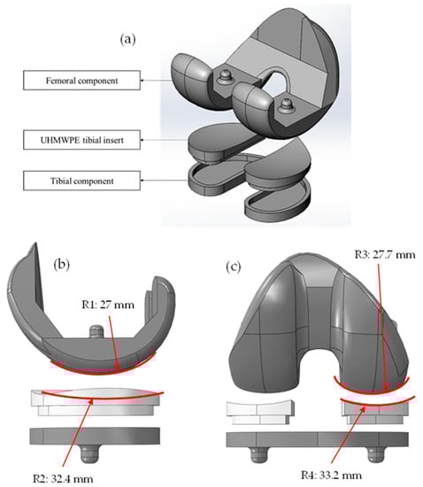
Figure 1.
(a) Components of BCR TKA knee implant model. (b) The radius of curvature of femoral and tibial inserts on sagittal plane. (c) The radius of curvature of femoral and tibial inserts on coronal plane. The curvature ratio is defined as the ratio of the tibial insert radius of curvature to the femoral radius of curvature.
Knee arthritis is a significant condition that affects around 70 million people globally, and total knee replacement has become a viable option for treating severe knee arthritis. In 2020, Zhang et al. showed that 8–25% of conventional TKA patients are not satisfied with their implant, whilst a greater satisfaction of patients who underwent the BCR TKA process has been reported [6]. Based on the report, it is necessary to construct mechanical studies to create biocompatible implants to optimise the design of knee implants; however, it is difficult to perform this on the structural mechanics of the human body, which involves bones, tissues, and other organs. Therefore, this study proposed the reduction of the peak value of the contact stress on the upper surface of the implant’s ultra-high-molecular-weight polyethylene (UHMWPE) tibial insert and its wear and to extend the life of the prosthesis by using the finite element (FE) model.
In designing a knee implant, considerations for its materials are needed because its design as well as the materials it is made of play critical roles in the effort to limit the stress level in the implant component [11]. The stresses accumulate at a faster rate when there is a greater load, and the contact stress that acts over the femoral component becomes more intense as the weight increases. Aseptic loosening is the most common type of knee implant failure, and this is because of UHMWPE wear [12,13,14]. Based on Archard wear law, volumetric wear is directly proportional to contact stress and sliding distance [15,16]. A retrieval study was performed that found that abrasive wear is initiated by third bodies and is determined by sliding distance and shear force. Meanwhile, surface wear, such as delamination and pitting, is affected by contact stress [17]. Thus, increasing the tibiofemoral conformity, which is defined as the femoral to tibial contact radii ratio [18], can reduce the contact stress and sliding distance, subsequently decreasing the occurrence of surface fatigue wear [19,20,21].
Taguchi’s orthogonal array method was initially developed by Genichi Taguchi; it is a statistical approach to optimise the selected experimental factor to improve the quality of the manufactured products [22,23]. The application of this method has been extended to chemistry, pharmaceuticals, and engineering [24,25]. The orthogonal array can efficiently decrease the number of computational simulations, thus leading to shorter preoperative planning time for TKA surgery. However, the application of the Taguchi orthogonal array in TKA finite element analysis was less pronounced by previous researchers. Recently, a study was conducted by Dong et al. to optimise the TKA implantation parameters using an orthogonal array based on finite element analysis [26]. Besides that, a very limited number of studies on the optimisation of tibiofemoral contact geometry have been performed. Previous researchers only conducted comparative studies to investigate the effect of tibiofemoral conformity of different implant designs on knee mechanics, i.e., knee kinematics and wear [27,28,29,30]. The optimisation of TKA implants was performed in recent studies to optimise the implantation parameters, i.e., varus–valgus angle and tibial rotation [26,31]; however, the optimisation of contact geometry at the tibiofemoral interface was not discussed.
Therefore, this study primarily aimed to investigate the effect of the design parameters of the BCR TKA knee implant on the mechanics of knee joints and optimise and individualise the knee implant design parameters using the Taguchi method incorporating finite element analysis (FEA). FEA is a powerful computational tool that has been applied in numerous structural analyses [26,32,33]. In this study, the design optimisation aimed to reduce wear at the tibial insert, hence improving the survival rate of the implant. In addition, clinical scores of the modern universal total knee arthroplasty system have been proven in studies to be of tremendous value not only to the surgeon but also to the healthcare system as a whole, thus making them an absolute necessity in the context of contemporary medical practice [34].
The scope of the study was to optimise and individualise the BCR TKA knee implant design parameters using FEA combined with the Taguchi technique. The significant design parameters that were taken into account were the curvature ratio of the sagittal plane, curvature ratio of the coronal plane, and tibial slope. The results of the peak contact stress and deformation of the developed designs were subsequently investigated to determine the best combination of design parameters. Nine FE models of BCR TKA knee joints were developed and then analysed using SIMULIA Abaqus to optimise the design parameters. ASTM F75 cobalt chromium molybdenum (Co-Cr-Mo) and UHMWPE were the materials used for the femoral component and tibial insert, respectively. They were used because, based on a study by Kohli et al. and static structural data, Co-Cr-Mo experienced the least amount of deformation as compared with titanium alloy and stainless steel [35]. Meanwhile, according to Bhandarkar et al., the stress behaviour of one of their material models with a tibial cushion constructed of UHMWPE material was superior to that of the other material models in terms of generating the least amount of stress [36].
2. Materials and Methods
An orthogonal array of the s element, denoted by LN (sm), was an N × m matrix. The number of rows, N of LN (sm), could be seen as a subset of the sm number of experiments for a complete factorial plan in the m experimental factor, each having s number of levels [37]. In this study, three different experimental factors were selected as the optimisation parameters of the BCR TKA UHMWPE tibial insert. The design parameters that were selected as experimental factors were A (curvature ratio of the UHMWPE tibial insert on the sagittal plane), B (curvature ratio of the UHMWPE tibial insert on the coronal plane), and C (tibial slope), as presented in Table 1. Taguchi’s orthogonal array, L9 (33), was utilised to estimate the factors that influence the contact stress and deformation of BCR TKA knee implants and to determine which factors were more important than others. Three levels were chosen for each factor, and these levels were used in the optimisation process. The curvature ratios of the UHMWPE tibial insert for both the sagittal and coronal planes were 1.0, 1.2, and 1.5, whilst the levels used for the tibial slope were 0°, 5°, and 10° [38]. Nine groups of experimental level combinations (the combinations of design parameters) were constructed based on the orthogonal experimental design proposed by Taguchi, as well as nine different BCR TKA knee implant models.

Table 1.
Knee implant experimental factors and design levels.
The combination of design parameters led to the development of nine different models of the BCR TKA knee implant, each of which featured nine different variations of the UHMWPE tibial insert. The base 3D model of BCR TKA was constructed based on the anatomical landmark of the knee joint of a female subject (age 29, mass = 70 kg, height = 170 cm) taken from a previous study [39]. Multiple assembled models with different parameters of the BCR TKA knee implant were established by altering this base model and reconstructing the UHMWPE tibial insert using SOLIDWORKS, thus meeting the requirements of factor combinations in Taguchi’s orthogonal experimental design. As shown in Figure 1a, each of these models was made up of a femoral component, a set of UHMWPE tibial inserts, and a tibial component. These three major components made up the entire model. Figure 1b,c show the radius of the curvature of the femoral component and the tibial insert on both the sagittal and coronal planes.
Herein, the FE model of this BCR TKA knee implant was developed using SIMULIA Abaqus. A validated FE model developed in our previous study was used [40,41]. Similar material properties, boundary conditions, and loads were set for each of the nine models to perform the FEA. The materials used for the femoral component and tibial insert were Co-Cr-Mo and UHMWPE, respectively. All materials were assumed to be homogeneous, isotropic, and linearly elastic [42]. The mechanical properties of the materials are presented in Table 2.
Table 2.
Mechanical properties of materials used in this study [43,44,45,46].
Then, to define the contact, the ‘hard’ contact model was used to prevent the transfer of tensile stress across the interface and decrease the penetration of the slave (femoral component) surface into the master (UHMWPE tibial insert) surface at the constraint points. A coefficient of friction of 0.04 was considered for the interaction between the femoral component and the UHMWPE tibial insert [47]. Surfaces on top of the femoral component and below the UHMWPE tibial insert were constrained to their reference points, as shown in Figure 2a. The UHMWPE tibial insert was set to be structurally fixed by prohibiting all translation degrees of freedom and by applying the boundary condition to their reference points. Meanwhile, the boundary condition for the femoral component was applied on its reference point to allow rotation and displacement on the vertical axis. Afterwards, each configuration of the models underwent the same load conditions. A vertical compressive load of 1000 N corresponding to the 100 kg mass of the subject was applied onto the midpoint of the transepicondylar axis of the femur along the y-axis to simulate the load, as shown in Figure 2 [48]. Subsequently, tetrahedral elements with an approximate element size of 1.2 mm [40,41,49,50,51,52] were used to mesh all models, and the number of elements of each component is presented in Table 3. Figure 2b shows the FE model of the knee implant. Finally, the FE simulations were performed.
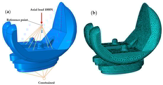
Figure 2.
(a) The boundary and loading conditions of the FE model. (b) FE model of the knee implant.
Table 3.
Mesh parameters of the BCR TKA knee implant model for each component.
An analysis of the range of the peak value of contact stress on the UHMWPE tibial insert was carried out to optimise the design. The range was determined using Equation (1):
where K is the mean of the peak values of contact stress, j is the experimental factor, i is the level, Rj is the range of experimental factor j, and m is the number of levels that were chosen based on a factor. The parameter that was most effective for the peak contact stress and deformation of the BCR TKA knee implant design can be determined from this equation. The greater range of factors indicates that the experimental factor gives a more significant influence on the results [26].
3. Results and Discussion
Each of the designs of the UHMWPE tibial insert affected different contact areas and stresses because of the variation of the BCR TKA knee design parameters. The values of deformation and the peak contact stress on the upper surface of the UHMWPE tibial insert of each model are shown in Table 4. The distribution of the contact stress on the UHMWPE tibial insert is shown in Figure 3. Meanwhile, the deformation of the UHMWPE tibial insert is shown in Figure 4. Stress and deformation were observed with an oval-shape that occurred in the region of the UHMWPE tibial insert.
Table 4.
Experimental level combinations of orthogonal experimental design.
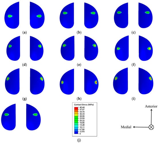
Figure 3.
Distribution of the contact stress on the UHMWPE tibial insert. (a) Model of the A1B1C1 group; (b) model of the A1B2C2 group; (c) model of the A1B3C3 group; (d) model of the A2B1C2 group; (e) model of the A2B2C3 group; (f) model of the A2B3C1 group; (g) model of the A3B1C3 group; (h) model of the A3B2C1 group; (i) model of the A3B3C2 group; and (j) model of the A1B1C2 group (optimised).
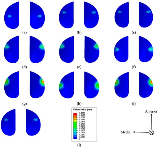
Figure 4.
Deformation of the UHMWPE tibial insert. (a) Model of the A1B1C1 group; (b) model of the A1B2C2 group; (c) model of the A1B3C3 group; (d) model of the A2B1C2 group; (e) model of the A2B2C3 group; (f) model of the A2B3C1 group; (g) model of the A3B1C3 group; (h) model of the A3B2C1 group; (i) model of the A3B3C2 group; and (j) model of the A1B1C2 group (optimised).
Observing the peak value of the contact stress, the highest peak value of the contact stress among the nine models was 40.44 MPa (group A3B2C1, Figure 3h), and it was found in the lateral compartment. The lowest value was 24.89 MPa (group A1B1C1, Figure 3a), which was also located in the lateral compartment. According to [42], every varus or valgus alignment causes a change in the medial and lateral contact stresses in comparison with the neutral-aligned model. The effect was stronger for more severe alignment configurations than it was for neutral alignment. However, the distribution of stress was mostly influenced by the design of the knee implant as well as the force that was delivered because of the static analysis that was performed and the absence of any alignment configurations. Given this, the maximum contact stress in each model was mostly on the lateral component. In addition to this, the maximal difference in the peak value of the contact stresses between the lateral and medial compartments was 6.32 MPa (group A3B2C1, Figure 3h). Based on these results, even minute alterations in the design parameters of the BCR TKA knee implant could lead to a relatively large change in contact stress (with a maximum change value of 15.55 MPa), thereby indicating the significance of an individualised and accurate design of the BCR TKA knee implant.
Observing the deformation of the UHMWPE tibial insert, the highest deformation among the nine models was 0.3714 mm (group A3B3C2, Figure 4i), which was found in the lateral compartment. The lowest value was 0.0822 mm (group A1B1C1, Figure 4a), which was also found in the lateral compartment. The deformation on the UHMWPE tibial insert surface was asymmetric on both sides, caused by the different contact stress distributions. In addition to this, the maximal difference in the deformation of the UHMWPE tibial insert between the lateral and medial compartments was 0.0718 mm (group A3B2C1, Figure 4h).
An analysis of the range of the peak values of the contact stress on UHMWPE was carried out for each of the nine different knee models using Equation (1). Moreover, the findings of the orthogonal experiment are provided in Table 5. As shown in the table, Kji denotes the mean of the peak values of the contact stress for the experimental factor j at level i. Based on the results of the calculation and the range analysis of the orthogonal experimental design, the curvature ratio on the sagittal plane had the greatest effect on the peak value of the contact stress, followed by the curvature ratio on the coronal plane, whilst the tibial slope had the smallest effect. The trend chart on the influence of various BCR TKA design parameters on the peak value of the contact stress was obtained through the range analysis and is depicted in Figure 5. The optimal design parameters for the BCR TKA UHMWPE tibial insert were obtained as A1B1C2, which had curvature ratios of 1.5 on both the sagittal and coronal planes, respectively, and a tibial slope of 5°.
Table 5.
Optimisation of the results of the orthogonal experimental design.
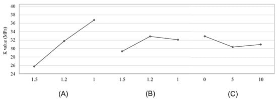
Figure 5.
Trend influence of implant design parameters at the peak value of the contact stress on the UHMWPE tibial insert. (A) Curvature ratio in sagittal plane. (B) Curvature ratio in coronal plane. (C) Tibial slope (°).
Individualised BCR TKA knee implant design parameters can be optimised to restore the mechanical alignment of the lower extremities, as well as promote consistent load distributions of both the medial and lateral compartments of the knee implant joint to reduce wear and extend prosthesis survival [53]. In this study, the result of the contact stress distribution of TKA models described was compatible with the previously published literature, particularly in terms of the tibial slope. The 3D model of the BCR TKA knee implant was reconstructed based on the optimised design parameters to verify the optimisation results of the orthogonal experimental design. For this optimised design, the number of elements in the meshing of the femoral component was 182,186, and the number of elements in the right and left tibia were 23,838 and 23,703 elements, respectively. The results showed that the peak value of contact stress on the UHMWPE tibial insert was 25.80 MPa (group A1B1C2, Figure 3j), which was located in the lateral compartment of the BCR TKA knee implant. The peak value of the contact stress was slightly higher than that of the lowest contact stress model, A1B1C1, by 0.91 MPa; however, it was reduced by 14.64 MPa from the highest value of 40.44 MPa (36.20%). The difference in the peak values of contact stress between the medial and the lateral compartments was only 0.48 MPa, and the load was more uniformly distributed than that of most of the other models. As for the deformation, the maximum deformation of this optimised model was 0.0835 mm, and the maximal difference in the deformation of the UHMWPE tibial insert between the lateral and medial compartments was only 0.0058 mm. In addition to this, the deformation was reduced by 0.2879 mm from the highest value of 0.3714 mm (77.52%).
This optimised implant design had a curvature ratio of 1.5 on the sagittal plane, a curvature ratio of 1.5 on the coronal plane, and a tibial slope of 5°. According to Shen et al., among four different posterior tibial slopes (0°, 3°, 6°, and 9°), the 3° and 6° posterior slopes showed more uniform distributions of contact stress in the medial and lateral compartments with the least polyethylene wear [54]. This was compatible with the findings of this study wherein the optimised design, model A1B1C2, also showed a uniform distribution of contact stress in both compartments. However, comparing it to the other models, the peak contact stress of the optimised design was slightly higher than in the models that had the lowest contact stress, A1B1C1 (with a curvature ratio of 1.5 on both the sagittal and coronal planes, respectively, and a 0° tibial slope) and A1B2C2 (with a curvature ratio of 1.5 and 1.2 on the sagittal and coronal planes, respectively, and a 5° tibial slope). This was caused by edge loading that induced a critical stress area on the tibial insert. According to Dhaka et al., the completeness and conformality of the contact are both directly impacted by the geometry of the contact [55]. It was found that the likelihood of crack initiation increased (because of the increase of contact stress) as the contact geometry became less flat and less conformal in the centre. The increase in crack length leads to a decrease in component fatigue life [33]. This indicates that the stress initiation increases as the corner becomes sharper at the tibiofemoral interfaces. From this, as the UHMWPE tibial insert was tilted 5° to fulfil the optimal design parameters, the UHMWPE tibial insert might have come in contact with a more acute geometry of the femoral component, thereby leading to a slightly higher contact stress than that of the other two models. Previous researchers [56,57] have investigated the effect that the radii of corners in a partially flat pad had on the fretting fatigue life and concluded that, in general, fretting fatigue life decreases with an increase in corner radii. This was attributed to increased stress caused by rounding the corners at the tibiofemoral contact.
However, this study had several limitations. We only simulated the variation of contact pressure on the plastic tibial insert under static conditions. The contact mechanics between the femoral component and the plastic insert under moving conditions, that is, flexional motion or under dynamic conditions, must be further studied to obtain more reliable data for optimisation purposes. To the best of our knowledge and according to the literature, these three parameters, which are the radius of curvature ratio on the sagittal plane, radius of curvature ratio on the coronal plane, and tibial slope, are important geometrical parameters that greatly affect the mechanics of knee implants including the contact stress distribution on the plastic insert as well as the kinematics (mobility) of the implanted knee joint. We selected three levels for each parameter to quantitatively represent the conformity of the tibial and femoral interface. Thus, more levels should be selected to perform more rigorous optimisation to study the effects of these parameters and investigate the effects of parameter variation on contact stress.
4. Conclusions
This study used the FEA method combined with Taguchi’s orthogonal experimental design to optimise the design parameters of the BCR TKA knee implant. This was to minimise the peak value of the contact stress and deformation of the UHMWPE tibial insert to reduce wear and extend the life of the implant. Even minute adjustments to the parameters of the design could result in large shifts in the peak value of the contact stress exerted on the UHMWPE, and this could negatively affect the implant’s ability to withstand wear over time. This method may be adopted for all patients undergoing TKA knee implants, and it can also be a new investigation for preoperative TKA planning. In addition, this study can offer a basis for the biomechanical decision of proper BCR TKA or other TKA knee implant designs. From this study, it was revealed that among the three parameters that affect the UHMWPE tibial insert’s peak contact stress and deformation, the curvature ratio on the sagittal plane had the greatest effect (range = 10.96), followed by the curvature ratio on the coronal plane (range = 3.54), and the tibial slope (range = 2.56). Finally, the optimal design parameters for the BCR TKA knee implant were a curvature ratio of 1.5 on both the sagittal and coronal planes and a tibial slope of 5°. Under these conditions, the peak contact stress and deformation were 25.80 MPa and 0.0835 mm, respectively.
Author Contributions
Conceptualisation, M.A.M.A. and M.F.M.M.; methodology, S.S. and M.A.A.; software, N.Q.M.M.; validation, S.S., M.A.M.A. and M.F.M.M.; formal analysis, N.Q.M.M.; investigation, N.Q.M.M.; resources, M.A.M.A.; data curation, S.S. and N.Q.M.M.; writing—original draft preparation, N.Q.M.M.; writing—review and editing, N.Q.M.M. and M.A.M.A.; visualization, N.Q.M.M.; supervision, M.A.M.A. and M.F.M.M.; project administration, M.A.A.; funding acquisition, M.A.M.A. All authors have read and agreed to the published version of the manuscript.
Funding
This research was funded by the Universiti Teknologi MARA, grant number 600-RMC/GPK 5/3 (098/2020).
Data Availability Statement
Not applicable.
Acknowledgments
The authors are pleased to acknowledge our undergraduate student, Muhammad Azim Mat Raffei, for the excellent assistance and technical support in the computational-aided drawing (CAD) model development.
Conflicts of Interest
The authors declare no conflict of interest.
References
- Comitini, S.; Tigani, D.; Leonetti, D.; Commessatti, M.; Cuoghi, F.; Barca, P.; Martucci, A.; Bettuzzi, C.; Amendola, L. Evolution in Knee Replacement Implant. Single Cell Biol. 2015, 4, 109. [Google Scholar] [CrossRef]
- Osmani, F.A.; Thakkar, S.C.; Collins, K.; Schwarzkopf, R. The utility of bicruciate-retaining total knee arthroplasty. Arthroplast Today 2017, 3, 61–66. [Google Scholar] [CrossRef]
- Dall’Oca, C.; Ricci, M.; Vecchini, E.; Giannini, N.; Lamberti, D.; Tromponi, C.; Magnan, B. Evolution of TKA design. Acta Biomed. 2017, 88, 17–31. [Google Scholar] [CrossRef]
- Mahomed, N.N.; Barrett, J.; Katz, J.N.; Baron, J.A.; Wright, J.; Losina, E. Epidemiology of Total Knee Replacement in the United States Medicare Population. J. Bone Jt. Surg. 2005, 87, 1222. [Google Scholar] [CrossRef]
- Traina, F.; De Fine, M.; Affatato, S. 5—Anatomy of the knee and suitable prostheses. In Wear of Orthopaedic Implants and Artificial Joints; Affatato, S., Ed.; Woodhead Publishing Series in Biomaterials; Woodhead Publishing: Sawston, UK, 2013; pp. 115–132. ISBN 978-0-85709-128-4. [Google Scholar]
- Zhang, Q.; Chen, Z.; Zhang, Z.; Jin, Z.; Muratoglu, O.K.; Varadarajan, K.M. Leveraging subject-specific musculoskeletal modeling to assess effect of anterior cruciate ligament retaining total knee arthroplasty during walking gait. Proc. Inst. Mech. Eng. Part H J. Eng. Med. 2020, 234, 1445–1456. [Google Scholar] [CrossRef]
- Pritchett, J.W. Bicruciate-retaining Total Knee Replacement Provides Satisfactory Function and Implant Survivorship at 23 Years. Clin. Orthop. Relat. Res. 2015, 473, 2327–2333. [Google Scholar] [CrossRef]
- Evans, J.T.; Walker, R.W.; Evans, J.P.; Blom, A.W.; Sayers, A.; Whitehouse, M.R. How long does a knee replacement last? A systematic review and meta-analysis of case series and national registry reports with more than 15 years of follow-up. Lancet 2019, 393, 655–663. [Google Scholar] [CrossRef]
- Kassam, A.-A.; Dieppe, P.; Toms, A. An analysis of time and money spent on investigating painful total knee replacements. Orthop. Proc. 2012, 94, 234. [Google Scholar] [CrossRef]
- Kallala, R.F.; Vanhegan, I.S.; Ibrahim, M.S.; Sarmah, S.; Haddad, F.S. Financial analysis of revision knee surgery based on NHS tariffs and hospital costs. Bone Jt. J. 2015, 97, 197–201. [Google Scholar] [CrossRef]
- Jackson Irudhayam, S.; Antony Prabu, D.; Jayakumar, K.S.; Hariram, V.; Sankaralingam, T. Stress distribution in knee Implant: A FEA study. Mater. Today Proc. 2022, 62, 977–980. [Google Scholar] [CrossRef]
- Haijie, L.; Dasen, L.; Tao, J.; Yi, Y.; Xiaodong, T.; Wei, G. Implant Survival and Complication Profiles of Endoprostheses for Treating Tumor Around the Knee in Adults: A Systematic Review of the Literature Over the Past 30 Years. J. Arthroplast. 2018, 33, 1275–1287.e3. [Google Scholar] [CrossRef] [PubMed]
- Henderson, E.R.; Groundland, J.S.; Pala, E.; Dennis, J.A.; Wooten, R.; Cheong, D.; Windhager, R.; Kotz, R.I.; Mercuri, M.; Funovics, P.T.; et al. Failure mode classification for tumor endoprostheses: Retrospective review of five institutions and a literature review. J. Bone Jt. Surg. Am. 2011, 93, 418–429. [Google Scholar] [CrossRef]
- Flannery, M.; McGloughlin, T.; Jones, E.; Birkinshaw, C. Analysis of wear and friction of total knee replacements: Part I. Wear assessment on a three station wear simulator. Wear 2008, 265, 999–1008. [Google Scholar] [CrossRef]
- Archard, J.F. Contact and Rubbing of Flat Surfaces. J. Appl. Phys. 1953, 24, 981–988. [Google Scholar] [CrossRef]
- Kauzlarich, J.J.; Williams, J.A. Archard wear and component geometry. Proc. Inst. Mech. Eng. Part J J. Eng. Tribol. 2001, 215, 387–403. [Google Scholar] [CrossRef]
- Wimmer, M.A.; Laurent, M.P.; Haman, J.D.; Jacobs, J.J.; Galante, J.O. Surface Damage Versus Tibial Polyethylene Insert Conformity: A Retrieval Study. Clin. Orthop. Relat. Res. 2012, 470, 1814–1825. [Google Scholar] [CrossRef]
- Pascau, A.; Guardia, B.; Puertolas, J.A.; Gómez-Barrena, E. Knee model of hydrodynamic lubrication during the gait cycle and the influence of prosthetic joint conformity. J. Orthop. Sci. 2009, 14, 68–75. [Google Scholar] [CrossRef]
- Bartel, D.L.; Bicknell, V.L.; Wright, T.M. The effect of conformity, thickness, and material on stresses in ultra-high molecular weight components for total joint replacement. J. Bone Jt. Surg. Am. 1986, 68, 1041–1051. [Google Scholar] [CrossRef]
- Huang, Z.; Ouyang, G.; Xiao, L. Rotating-platform knee arthroplasty: A review and update. Orthop. Surg. 2011, 3, 224–228. [Google Scholar] [CrossRef]
- Kurtz, S.M.; Bartel, D.L.; Rimnac, C.M. Postirradiation aging affects stress and strain in polyethylene components. Clin. Orthop. Relat. Res. 1998, 350, 209–220. [Google Scholar] [CrossRef]
- Sabarish, K.V.; Pratheeba, P. An experimental analysis on structural beam with Taguchi orthogonal array. Mater. Today Proc. 2020, 22, 874–878. [Google Scholar] [CrossRef]
- Tekade, R.K.; Chougule, M.B. Formulation Development and Evaluation of Hybrid Nanocarrier for Cancer Therapy: Taguchi Orthogonal Array Based Design. BioMed Res. Int. 2013, 2013, e712678. [Google Scholar] [CrossRef]
- Nagarjun, P.A.; Rao, R.S.; Rajesham, S.; Rao, L.V. Optimization of lactic acid production in SSF by Lactobacillus amylovorus NRRL B-4542 using Taguchi methodology. J. Microbiol. 2005, 43, 38–43. [Google Scholar]
- Varshosaz, J.; Eskandari, S.; Tabakhian, M. Production and optimization of valproic acid nanostructured lipid carriers by the Taguchi design. Pharm. Dev. Technol. 2010, 15, 89–96. [Google Scholar] [CrossRef]
- Dong, Y.; Zhang, Z.; Dong, W.; Hu, G.; Wang, B.; Mou, Z. An optimization method for implantation parameters of individualized TKA tibial prosthesis based on finite element analysis and orthogonal experimental design. BMC Musculoskelet. Disord. 2020, 21, 165. [Google Scholar] [CrossRef]
- Brockett, C.; Carbone, S.; Fisher, J.; Jennings, L. Influence of conformity on the wear of total knee replacement: An experimental study. Proc. Inst. Mech. Eng. Part H J. Eng. Med. 2017, 232, 127–134. [Google Scholar] [CrossRef]
- Koh, Y.-G.; Park, K.-M.; Kang, K.-T. The biomechanical effect of tibiofemoral conformity design for patient-specific cruciate retainging total knee arthroplasty using computational simulation. J. Exp. Orthop. 2019, 6, 23. [Google Scholar] [CrossRef]
- Khasian, M.; Meccia, B.A.; LaCour, M.T.; Komistek, R.D. Effects of the Medial Plateau Bearing Insert Conformity on Mid-Flexion Paradoxical Motion in a Posterior-Stabilized Total Knee Arthroplasty Design. J. Arthroplast. 2021, 36, 2386–2392. [Google Scholar] [CrossRef]
- Indelli, P.F.; Risitano, S.; Hall, K.E.; Leonardi, E.; Migliore, E. Effect of polyethylene conformity on total knee arthroplasty early clinical outcomes. Knee Surg. Sport. Traumatol. Arthrosc. 2019, 27, 1028–1034. [Google Scholar] [CrossRef]
- Mou, Z.; Dong, W.; Zhang, Z.; Wang, A.; Hu, G.; Wang, B.; Dong, Y. Optimization of parameters for femoral component implantation during TKA using finite element analysis and orthogonal array testing. J. Orthop. Surg. Res. 2018, 13, 179. [Google Scholar] [CrossRef]
- Tang, Q.; Twumasi, J.O.; Hu, J.; Wang, X.; Yu, T. Finite element simulation of photoacoustic fiber optic sensors for surface corrosion detection on a steel rod. In Proceedings of the Nondestructive Characterization and Monitoring of Advanced Materials, Aerospace, Civil Infrastructure, and Transportation XII, Denver, CO, USA, 5–8 March 2018; SPIE: Paris, France, 2018; Volume 10599, pp. 341–353. [Google Scholar]
- Masoudi Nejad, R.; Noroozian Rizi, P.; Zoei, M.S.; Aliakbari, K.; Ghasemi, H. Failure Analysis of a Working Roll Under the Influence of the Stress Field Due to Hot Rolling Process. J. Fail. Anal. Preven. 2021, 21, 870–879. [Google Scholar] [CrossRef]
- Bonner, B.; Law, J.I.; Dacus, E.; Hofmann, E. The Modern Universal Total Knee Arthroplasty: Maximized Value, Streamlined Efficiency. Available online: https://econpapers.repec.org/bookchap/itopchaps/226804.htm (accessed on 14 December 2022).
- Kohli, A.; Mathad, M.; V Hosamani, S.; Adagimath, M.K.; Kotturshettar, B.B. Finite element analysis of knee joint implant for varying bio material using ANSYS. Mater. Today Proc. 2022, 59, 941–950. [Google Scholar] [CrossRef]
- Bhandarkar, S.; Dhatrak, P. Optimization of a knee implant with different biomaterials using finite element analysis. Mater. Today Proc. 2022, 59, 459–467. [Google Scholar] [CrossRef]
- Kacker, R.N.; Lagergren, E.S.; Filliben, J.J. Taguchi’s Orthogonal Arrays Are Classical Designs of Experiments. J. Res. Natl. Inst. Stand. Technol. 1991, 96, 577–591. [Google Scholar] [CrossRef]
- Singerman, R.; Dean, J.C.; Pagan, H.D.; Goldberg, V.M. Decreased posterior tibial slope increases strain in the posterior cruciate ligament following total knee arthroplasty. J. Arthroplast. 1996, 11, 99–103. [Google Scholar] [CrossRef]
- Guess, T.M.; Razu, S. Loading of the medial meniscus in the ACL deficient knee: A multibody computational study. Med. Eng. Phys. 2017, 41, 26–34. [Google Scholar] [CrossRef]
- Mohd Anuar, M.A.; Todo, M.; Nagamine, R.; Hirokawa, S. Dynamic Finite Element Analysis of Mobile Bearing Type Knee Prosthesis under Deep Flexional Motion. Sci. World J. 2014, 2014, 586921. [Google Scholar] [CrossRef]
- Anuar, M.A.M.; Todo, M.; Nagamine, R. Computational Model for Mechanics of Total Knee Replacement: Effect of Tibial Rotation during Deep Flexion in Relation to Post-Cam Design. Int. J. Biosci. Biochem. Bioinform. 2014. [Google Scholar] [CrossRef]
- Innocenti, B.; Bellemans, J.; Catani, F. Deviations from Optimal Alignment in TKA: Is There a Biomechanical Difference Between Femoral or Tibial Component Alignment? J. Arthroplast. 2016, 31, 295–301. [Google Scholar] [CrossRef]
- Dayyoub, T.; Maksimkin, A.V.; Kaloshkin, S.; Kolesnikov, E.; Chukov, D.; Dyachkova, T.P.; Gutnik, I. The Structure and Mechanical Properties of the UHMWPE Films Modified by the Mixture of Graphene Nanoplates with Polyaniline. Polymers 2018, 11, 23. [Google Scholar] [CrossRef]
- Baron, S.; Desmond, D.; Ahearne, E. The fundamental mechanisms of wear of cemented carbide in continuous cutting of medical grade cobalt chromium alloy (ASTM F75). Wear 2019, 424–425, 89–96. [Google Scholar] [CrossRef]
- Wang, A.; Yau, S.-S.; Essner, A.; Herrera, L.; Manley, M.; Dumbleton, J. A Highly Crosslinked UHMWPE for CR and PS Total Knee Arthroplasties. J. Arthroplast. 2008, 23, 559–566. [Google Scholar] [CrossRef] [PubMed]
- Fleming, T.J.; Kavanagh, A.; Duggan, G. The effect of melt temperature on the mechanical properties of cast ASTM F75 CoCrMo alloy as explained by nitrogen and oxygen content. J. Mater. Res. Technol. 2020, 9, 9479–9486. [Google Scholar] [CrossRef]
- Takian, W.; Rooppakhun, S.; Ariyarit, A.; Sucharitpwatskul, S. Optimal Conformity Design of Tibial Insert Component Based on ISO Standard Wear Test Using Finite Element Analysis and Surrogate Model. Symmetry 2021, 13, 2377. [Google Scholar] [CrossRef]
- D’Lima, D.D.; Fregly, B.J.; Patil, S.; Steklov, N.; Colwell, C.W. Knee joint forces: Prediction, measurement, and significance. Proc. Inst. Mech. Eng. H 2012, 226, 95–102. [Google Scholar] [CrossRef]
- Kang, K.-T.; Son, J.; Kwon, S.K.; Kwon, O.-R.; Park, J.-H.; Koh, Y.-G. Finite element analysis for the biomechanical effect of tibial insert materials in total knee arthroplasty. Compos. Struct. 2018, 201, 141–150. [Google Scholar] [CrossRef]
- Kwon, O.-R.; Kang, K.-T.; Son, J.; Kwon, S.-K.; Jo, S.-B.; Suh, D.-S.; Choi, Y.-J.; Kim, H.-J.; Koh, Y.-G. Biomechanical comparison of fixed- and mobile-bearing for unicomparmental knee arthroplasty using finite element analysis. J. Orthop. Res. 2014, 32, 338–345. [Google Scholar] [CrossRef]
- Koh, Y.-G.; Park, K.-M.; Lee, H.-Y.; Kang, K.-T. Influence of tibiofemoral congruency design on the wear of patient-specific unicompartmental knee arthroplasty using finite element analysis. Bone Jt. Res. 2019, 8, 156–164. [Google Scholar] [CrossRef]
- Kang, K.-T.; Son, J.; Kim, H.-J.; Baek, C.; Kwon, O.-R.; Koh, Y.-G. Wear predictions for UHMWPE material with various surface properties used on the femoral component in total knee arthroplasty: A computational simulation study. J. Mater. Sci. Mater. Med. 2017, 28, 105. [Google Scholar] [CrossRef]
- Fang, D.M.; Ritter, M.A.; Davis, K.E. Coronal alignment in total knee arthroplasty: Just how important is it? J. Arthroplast. 2009, 24, 39–43. [Google Scholar] [CrossRef]
- Shen, Y.; Li, X.; Fu, X.; Wang, W. A 3D finite element model to investigate prosthetic interface stresses of different posterior tibial slope. Knee Surg. Sport. Traumatol. Arthrosc. 2015, 23, 3330–3336. [Google Scholar] [CrossRef] [PubMed]
- Dhaka, P.; Prakash, R.V. Effect of Contact Geometry on the Contact Stresses in a Flat with Round Edge Contact. Frat. Ed Integrità Strutt. 2019, 13, 630–638. [Google Scholar] [CrossRef]
- Mall, S.; Naboulsi, S.; Namjoshi, S.A. Contact geometry effects on fretting fatigue crack initiation behaviour of Ti–6Al–4V. Tribol. Mater. Surf. Interfaces 2008, 2, 25–32. [Google Scholar] [CrossRef]
- Juoksukangas, J.; Lehtovaara, A.; Mäntylä, A. The effect of contact edge geometry on fretting fatigue behavior in complete contacts. Wear 2013, 308, 206–212. [Google Scholar] [CrossRef]
Disclaimer/Publisher’s Note: The statements, opinions and data contained in all publications are solely those of the individual author(s) and contributor(s) and not of MDPI and/or the editor(s). MDPI and/or the editor(s) disclaim responsibility for any injury to people or property resulting from any ideas, methods, instructions or products referred to in the content. |
© 2023 by the authors. Licensee MDPI, Basel, Switzerland. This article is an open access article distributed under the terms and conditions of the Creative Commons Attribution (CC BY) license (https://creativecommons.org/licenses/by/4.0/).