1. Introduction
Today, reciprocating machines are used in various process installations and power plants: internal (and external) combustion engines, compressors, pumps, etc. Engineers and scientists are constantly looking for ways to improve their performance by redesigning or tweaking the operating cycle parameters [
1,
2]. For example, to increase the efficiency and performance of reciprocating engines, experimental data on the rate of heat transfer of gas flows in gas exchange systems (inlet and outlet systems) are needed [
3]. These data will make it possible to create new (more accurate) mathematical models and methods for calculating structures and processes in reciprocating machines. Therefore, one of the tasks of experimental research focussing on the rate of heat transfer of gas flows in inlet and outlet systems is to study the instantaneous local heat transfer under the conditions of gas-dynamic unsteadiness (pulsating flows), as well as the mathematical description of those processes. In the engineering aspect, needed are data on the influence of the initial parameters of the flow and the design of gas-dynamic systems on the heat-transfer coefficient. These data can be used to adjust (verify) mathematical models and refine methods for engineering calculations of gas exchange processes in reciprocating internal combustion engines (RICEs). The practical relevance of determining the rate of heat transfer in the RICE is that it is necessary to calculate the amount of heating of the working medium (cylinder filling process), exhaust gas cooling (cylinder cleaning, the amount of heat in the turbocharger) and determining thermal stresses in the nodes and parts of gas-dynamic systems.
Presented below are the latest achievements of scientists and engineers in the field of improving thermal and mechanical processes in the intake and exhaust systems of reciprocating machines.
There are studies assessing the level of heat transfer in the channels and elements of the head of a piston engine [
4,
5,
6]. M. Cerdoun and co-authors studied the mutual influence of heat flow for the inlet and outlet channels in the block head [
4]. The data obtained are important for assessing the heating of the working medium and taking into account thermal stresses in valves. X. Fan and others studied the rate of heat transfer in the block head during the compression of the working medium in the engine cylinder [
5]. It should be noted that heat transfer was studied in an unsteady statement of the problem. As a result, temperature fields and detailed information about the heat flow in the channels of the engine block head were obtained. M.A.S.M. Hassan and colleagues evaluated the rate of heat transfer in the parts of the engine block head, taking into account the flows in the intake and exhaust channels, as well as the engine cylinder [
6]. It was found that as the engine crankshaft speed increases, the thermal load on the elements in the engine block head also increases. There is focused research to assess thermal stresses in the outlet valves of the RIC engine, taking into account the unsteady heat exchange of gas flows in the channels of the block head and the engine cylinder [
7,
8]. This emphasizes the importance of obtaining experimental data on the rate of heat transfer of unsteady gas flows in the inlet and outlet pipelines in order to refine the boundary conditions in front of the channels in the block head.
In addition, it is known that the features of gas dynamics and the level of heat transfer in the gas exchange system have a significant effect on the thermomechanical processes in the RICE cylinder [
9,
10,
11]. Thus, L. Teodosio et al. proposed a one-dimensional mathematical model of a reciprocating engine, which contains a turbulent combustion sub-model and an improved sub-model for heat transfer in cylinders and outlet pipelines [
9]. The key purpose of this model is to determine the efficiency of RICE in a wide range of load changes and operating modes. A. Nemati et al. compared various turbulence models in forecasting the level of heat transfer and environmental friendliness in a cylinder [
10]. The authors formulated recommendations on the use of one or another turbulence model in a particular case. Z. Liu and J. Liu evaluated the rate of heat transfer under different conditions (pressures) at the inlet [
11].
There are a large number of articles focussing on the modernization of the design of inlet and/or outlet pipelines by improving the gas dynamics and heat transfer of flows in order to enhance the efficiency and environmental friendliness of RICE [
12,
13,
14,
15]. H. Talati et al. developed an original design of the intake system with a variable length of the pipeline and four controlled throttle valves [
12]. It is shown that the specific fuel flow decreased by 0.83%, and the torque increased by 7.23% compared to the basic configuration of the intake system. This was achieved through the gas-dynamic perfection of the design and optimization of heat transfer during the intake of the working medium into the engine cylinder. P.A. Lakshminarayanan and colleagues studied the effects of the diameter of the intake and outlet pipelines on the temperature after the turbocharger turbine during engine operation in a steady state and transient conditions [
13]. In turn, G. Wang et al. found that by upgrading the intake system and fuel supply system, it is possible to increase power by 3.5% and reduce specific fuel consumption by almost 2 g/(kWh) [
14]. Results in the field of ecology were obtained in articles [
16,
17]. Scientists carried out the modernization of the design of the intake system in order to reduce the amount of harmful substances in the exhaust gases. It has been established that the optimization of the gas-dynamic and heat-exchange characteristics of flows in the intake system can lead to an improvement in the environmental friendliness of the engine by up to 47%. This confirms the relevance of obtaining data on the local heat transfer of pulsating flows in the intake system of reciprocating machines.
It is also known that the physical conditions (pressure, temperature, humidity, etc.) at the inlet have a significant impact on the technical and economic parameters of RICE [
18,
19,
20]. Thus, W. Guan et al. refined and tuned the intake system of a gas engine by optimizing the initial conditions and the engine control system [
18]. As a result, the effective efficiency of the engine increased to 47.4%. W. Choi and H.H. Song studied the effects of initial conditions in the intake system on the gas-dynamic and thermal-mechanical characteristics of flows in the piston engine cylinder [
19]. An original mathematical model was created for this research. It is shown that the initial conditions at the inlet have a significant effect on the values of the maximum pressure and temperature of the cycle. S. Lee et al. studied the composition of the working medium and the initial conditions in the intake system on the technical and economic performance of a hydrogen engine [
20].
It is worth highlighting studies in which researchers and professionals develop special technical devices for their installation in the exhaust system in order to additionally use the energy (temperature) of the exhaust gases of RICE [
21,
22,
23,
24]. For example, P. Fernández-Yáñez and colleagues studied the thermoelectric generator installation in the exhaust system of RICE [
21]. Additional power generation, flow coefficient, and heat transfer rate were evaluated for various designs of thermoelectric generators and exhaust piping. It has been established that the energy produced from a thermoelectric generator is several times higher than the resistance losses. D. Jiang et al. studied the efficiency of a waste heat boiler for exhaust gases from a marine engine [
22]. Optimal operating modes of the engine and waste heat boiler were obtained on the basis of data on average speeds and temperatures in the exhaust system of the RICE. M. Bohm et al. proposed an original thermal energy storage system to improve the environmental performance of a reciprocating engine [
23]. This system is designed to equalize the temperature field in the exhaust system and control the rate of heat exchange in order to increase the efficiency of exhaust gas converters. F. Catapano and colleagues studied the efficiency of the joint operation of the Stirling engine and the internal combustion engine in order to enhance the efficiency of a power plant [
24]. The presented studies emphasize the importance of obtaining detailed information on local and average heat-transfer coefficients in intake and exhaust systems in order to find ways to enhance the efficiency and environmental friendliness of RICE. Moreover, reliable experimental data on the unsteady heat transfer of pulsating flows in gas dynamic systems are necessary for the development of new mathematical models and the verification of existing ones [
25,
26,
27,
28]. In addition, artificial intelligence algorithms are used to optimize thermophysical processes in the gas exchange system of reciprocating machines [
29]. Accordingly, it can be assumed that reliable experimental data on the instantaneous heat transfer of pulsating in the intake and exhaust systems and their mathematical description are needed to adjust these algorithms.
It should be noted that there are mathematical models of thermodynamic processes in RICE with different levels of detail [
30,
31,
32,
33]. X. Margot and colleagues developed a one-dimensional mathematical model for calculating heat losses in a single-cylinder gasoline engine with direct fuel injection into the cylinder [
30]. V. Ayhan et al. improved the environmental performance of the engine based on the simulation of thermodynamic processes in RICE with an emphasis on the gas exchange system [
31]. C. Depcik et al. developed an original mathematical model for engines with small cylinder volumes (up to 100 cm
3) [
33]. It should be noted that there are also mathematical models of thermodynamic processes in two-stroke engines [
34,
35]. Their key features lie in the correct description of the physical processes in the gas exchange system.
It should be noted that there is a limited number of experimental and numerical studies of processes in the intake and exhaust pipelines of reciprocating machines in dynamics, i.e., as applied to pulsating, unsteady gas flows. Thus, the main objectives of this research are:
- –
To create experimental benches (full-scale models) for the study of unsteady heat transfer of pulsating gas flows in gas-dynamic systems simulating the physical features of gas exchange processes in reciprocating engines.
- –
To obtain data on the instantaneous values of the local heat-transfer coefficient of unsteady gas flows in the inlet and outlet pipelines of the piston engine model based on experimental studies.
- –
To carry out a spectral analysis of experimental data on unsteady heat transfer in the inlet and outlet pipelines of the piston engine model.
- –
Mathematical description of the change in the local heat-transfer coefficient of gas flows in the inlet and outlet pipelines from the key physical parameters typical of gas exchange processes in reciprocating engines.
- –
Determination of the average rate of heat transfer in the inlet and outlet pipelines in dimensional and dimensionless form from the key parameters of the gas exchange process, as well as a mathematical description of those dependencies.
In this case, there is a mathematical problem, which consists of the possibility of an analytical description (approximation of experimental data) of a change in the local heat transfer coefficient of a pulsating flow in the inlet and outlet systems of reciprocating machines with acceptable accuracy. The solution to this problem contains several subtasks:
- –
Selection of a mathematical apparatus for approximating complex functions (experimental data).
- –
Choice of representation of the mathematical description of data, which is applicable for engineering calculations and the creation of mathematical models.
- –
Evaluation of the accuracy of the mathematical description of the experimental data.
2. Description of Experimental Benches and Measuring System
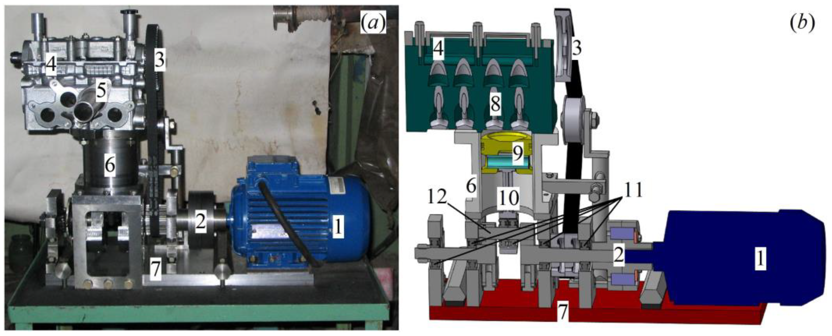
To study the unsteady heat transfer of gas flows in the intake system, a dynamic model of a piston engine driven by an electric motor was developed (
Figure 1).
The model contained all the key components of a piston machine, such as a crankshaft, a connecting rod, a piston, a cylinder, a valve mechanism with a camshaft, and intake and exhaust systems. The geometric dimensions and design of the main elements of the model were taken from the automobile RICE of the VAZ company (Togliatty, Russia). The cylinder diameter was 82 mm, and the piston stroke was 71 mm. The block head was completely borrowed from the Russian Oka car. The main parameters of the gas distribution mechanism for the study of the intake process were as follows:
- –
Inlet valve opening—33 degrees before the top dead center (TDC).
- –
Closing of the inlet valve—79 degrees after the bottom dead center (BDC).
- –
The inlet valve lift was 9.2 mm.
The crankshaft of the piston engine model was driven by an electric motor. The crankshaft speed was regulated in the range from 600 rpm to 3000 rpm by means of a frequency converter with an accuracy of 0.2%. The studies were carried out at a pitch of 500 rpm. Consequently, the camshaft speed ranged from 300 rpm to 1500 rpm. The pulsations of the airflow in the intake system were with a frequency of 5–25 Hz. The air circulation in the intake system was created due to discharging in the cylinder due to the movement of the piston from TDC to BDC and the valve mechanism operation. The piston engine model did not have a fuel system, so the fuel-air mixture in the cylinder was not combusted. Thus, the research results do not take into account the heat from the combustion process or hot combustion products. However, this is offset by the use of a thermal sensor with temperature conditions characteristic of piston engines. It can be stated that the developed experimental stand maximally imitates the physical features of the flows in the intake system during the operation of the RICE (pulsation frequency, velocity, pressure, and temperature).
The working medium in the studies was the air with temperature t = 21 ± 1 °C and pressure po = 98 ± 0.2 kPa.
To study the unsteady heat transfer of gas flows in the exhaust system of a reciprocating machine, developed was another experimental setup also driven by an electric motor (
Figure 2).
In this case, the model contained such elements as the cylinder, valve train with camshaft, intake, and exhaust systems. The cylinder diameter was 82 mm, height—71 mm. The block head was completely borrowed from the Russian car VAZ-Oka. The camshaft of the model was driven by an electric motor. The shaft rotation frequency was regulated in the range from 300 rpm to 1500 rpm by means of a frequency converter with an accuracy of 0.2%. Pulsations of the gas flow in the exhaust system were with a frequency of 2.5–12.5 Hz. The key parameters of the gas distribution mechanism to study the exhaust process were as follows:
- –
Opening of the outlet valve—47 degrees before BDC.
- –
Closing of the outlet valve—17 degrees after TDC.
- –
The height of the outlet valve lift was 9.2 mm.
Air circulation in the exhaust system was created due to excess pressure in the cylinder (pb = 0.05–0.2 mPa) and the operation of the valve mechanism. The initial pressure in the cylinder pb was created by an external source of compressed air. The working medium in the studies was air with a temperature of t = 31 ± 1 °C. Therefore, the developed experimental bench imitates the physical features of the flows in the exhaust system during the operation of reciprocating machines.
The key elements of gas dynamic systems for this study are shown in
Figure 3: straight pipe, curved channel in the head, valve, and cylinder.
The inlet pipeline had the following geometric dimensions: inner diameter—32 mm, length 350 mm. The outlet pipeline had a diameter of 30 mm and a length of 400 mm. The curved channel in the block head for the intake system had a length of 150 mm and a diameter of 31 mm. The length of the curved channel for the exhaust systems was 135 mm, and the diameter was 29 mm. The inlet valve had a bore diameter of 32 mm, and the outlet valve—30 mm. The cylinder in both cases had a diameter of 32 mm and a height of 71 mm.
During the experiments, the following parameters were measured: instantaneous values of the local air flow rate wx, local heat-transfer coefficient αx, crankshaft speed n, pressure p, and temperature t of the airflow.
The values of
wx and α
x were determined with the thermal anemometry method using a constant temperature hot-wire anemometer and two types of filament sensors [
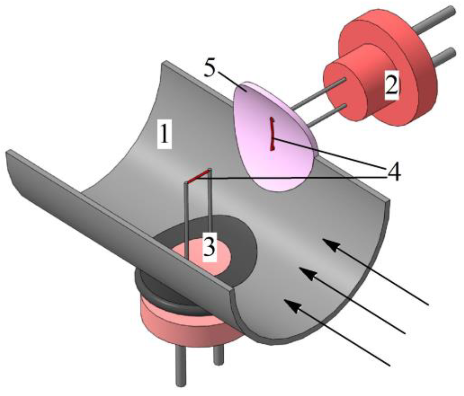
36]. A general view of the control section in the inlet or outlet pipeline is shown in
Figure 4. There were three control sections in the intake and outlet pipelines at distances of 40 mm, 100 mm, and 200 mm from the window in the cylinder head.
The thermal sensors used a nichrome filament with a diameter of 5 μm and a length of 5 mm. A hot-wire anemometer sensor with a thread located approximately in the center of the pipeline (perpendicular to the oncoming flow) was used to determine the instantaneous values of the airflow velocity. A sensor with a thread located on a fluoroplastic substrate flush with the pipeline surface (also perpendicular to the oncoming flow) was used to determine the local heat-transfer coefficient.
The rate of heat transfer of pulsating flows in gas-dynamic systems of complex configuration is affected by the smallest details of the thermohydraulic situation near the sensor, which should be the same as near the wall of a real object. Preliminary analysis and experiments have shown that it is not possible in this case to provide these conditions when implementing known methods for determining the local heat-transfer coefficient with either wire sensors or film sensors. Direct determination of α
x from the removed heat flux leads to disproportionately large values of the heat-transfer coefficient since a heated local microelement creates around itself a different gas-dynamic and thermal environment than an extended hot wall. Therefore, the indirect calibration method was chosen based on the indicators of the local rate of heat transfer of a well-studied process, steady heat transfer in a long straight pipe with a circular cross-section (
l/
d ≈ 50) [
37]. The method for determining the local heat-transfer coefficient is described in more detail in articles [
37,
38]. The typical relative uncertainty in determining the local flow rate was 5.3%, with the local heat-transfer coefficient being 10.1%.
The crankshaft speed was determined with a tachometer (relative uncertainty—1.5%).
Data from hot-wire anemometers and a tachometer were fed into an automated measuring system based on an L-Card analog-to-digital converter. Further, the data were received by a computer for processing in custom-made LGraph (v. 2.36.01) software (L-Card, Moscow, Russia).
The speed of the measuring system was sufficient to study the unsteady gas dynamics and heat transfer of pulsating air flows in the intake and exhaust systems of the piston engine model for the specified camshaft speeds.
3. Unsteady Heat Transfer in the Intake System
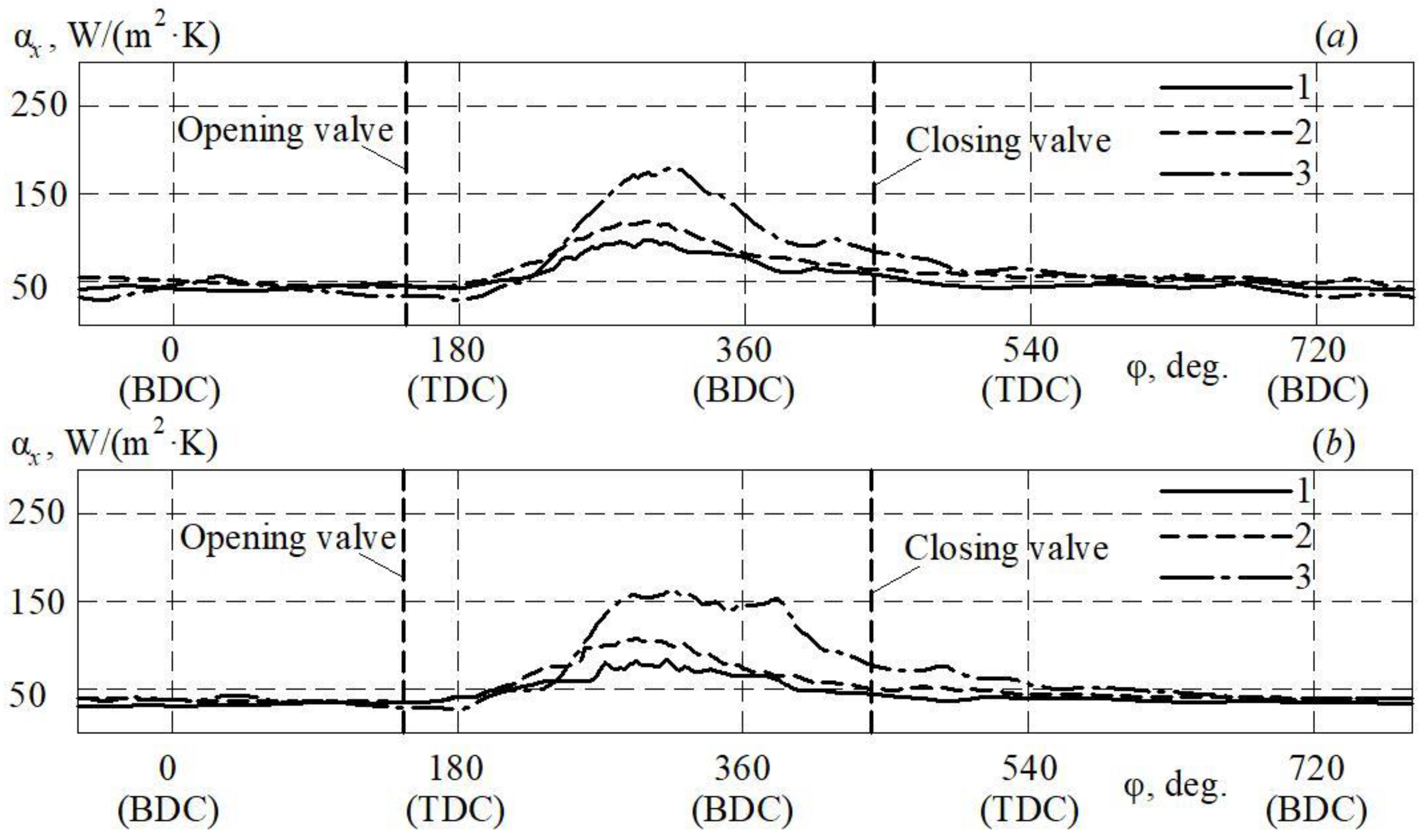
The change in the local heat-transfer coefficient of pulsating air flows in the inlet pipeline for a complete cycle of a piston engine (i.e., for two revolutions of the crankshaft) at different shaft speeds is shown in
Figure 5.
A complete engine cycle is carried out in two revolutions of the crankshaft (720 degrees). In this case, the intake process (cylinder filling) is carried out once from the opening of the intake valve to its closing. This cycle then repeats again. The movement of gas in the intake pipeline is carried out during the intake process. Accordingly, the heat transfer rate is also determined for the valve open period. From
Figure 5, it can be seen that the variation of the local heat-transfer coefficient is in the range of between 40 and 180 W/(m
2·K). The data obtained are in good agreement with the results from the article [
5]. It has been found that the maximum values of the local heat-transfer coefficient α
x increase with increasing crankshaft speed and are in the range from 95 to 180 W/(m
2·K) in the cross-section at a distance
lx = 100 mm. As the control section moves away from the block head (
lx = 200 mm), the maximum values of α
x decrease to 65–155 W/(m
2·K). The influence of the crankshaft speed on the rate of heat transfer in the RICE gas exchange system is well in line with the data of the article [
4]. At the same time, the most intense change in the local heat-transfer coefficient can be recorded during the period of the open inlet valve (the period when air flows through the inlet pipeline). α
x values grow from 180 degrees to 300 degrees. The local heat-transfer coefficient reaches its maximum value in the region of 300 degrees, which is typical of all control sections and all crankshaft speeds. Then there is a decrease in α
x up to 540 degrees, after which the dependence α
x =
f (φ) stabilizes around a constant value of 40–45 W/(m
2·K). Consequently, in a short period of time (hundredths of a second), the local heat-transfer coefficient changes from 40 to 180 W/(m
2·K). Such significant fluctuations in α
x should be taken into account when calculating gas exchange processes and when designing intake and exhaust systems in reciprocating machines. Moreover, it is known that the configuration of the pipeline also has a significant effect on the level of heat transfer in the gas exchange system of a reciprocating machine. [
39,
40].
Dependences αx = f (φ) can additionally be used as data for adjusting artificial intelligence algorithms for creating real-time control systems for reciprocating machines based on the level of heat transfer in the gas-dynamic system.
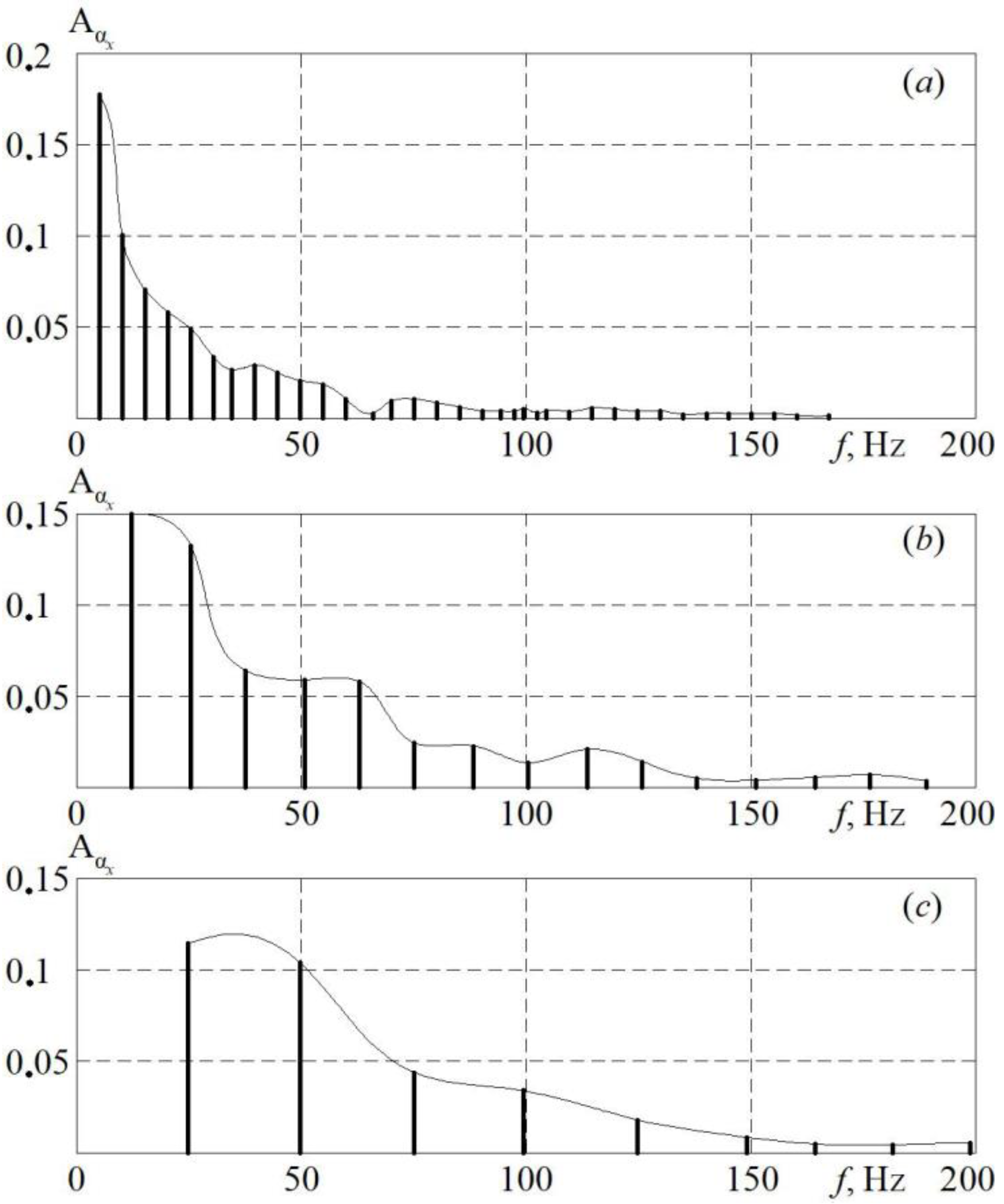
To assess dynamic changes in the local heat-transfer coefficient in the inlet pipeline, graphs of the spectrum amplitudes for the function α
x =
f (φ) were obtained (
Figure 6).
Physical processes in reciprocating machines are cyclic in accordance with the features of functioning. Therefore, the functions α = f (w) and α = f (n) are periodic in time. Accordingly, spectral analysis is an effective tool for revealing physical patterns.
Figure 6 shows that the first significant frequency of the spectrum corresponds to the camshaft speed of the RICE model: 10 Hz for
n = 600 rpm, 12.5 Hz for
n = 1500 rpm, and 25 Hz for
n = 3000 rpm. This is explained by the fact that the speed of rotation of the crankshaft determines the main frequency of oscillations of the local heat transfer coefficient. Subsequent amplitudes indicate that harmonics up to the tenth are observed in the signal spectrum. The first significant amplitude always has the largest value and is determined by the operating mode of the piston engine model (or, in other words, the crankshaft speed). As the pulsation frequency
f increases, the
Aα amplitudes decrease. In this case, at
n = 600 rpm, the significant frequencies of the spectrum extend up to 80 Hz, and at
n = 3000 rpm, up to 200 Hz. Accordingly, it can be concluded that with an increase in the frequency of rotation of the crankshaft, the dynamics of the process become more complicated. It should also be noted that significant frequencies have a multiplicity equal to the value of the first significant frequency for the corresponding mode of operation of the RICE model (10, 12.5, and 25 Hz, respectively).
Thus, as a result of the research, it was found that the instantaneous local heat transfer in the inlet pipeline of the RICE model depends on several parameters, such as crankshaft speed n, crankshaft rotation angle φ, distance from the inlet lx and environmental conditions (temperature t and pressure p), i.e., αx = f (n, φ, lx, t, p). As a result of experimental data approximation, obtained were equations for calculating the local heat-transfer coefficient with an error (root mean square deviation) of 12%. Approximation was with the least squares method. In order to obtain a simpler calculation equation, the dependence αx = f (φ) was divided into two sections, an uplift section (160° < φ < 300°) and a drop-down section (300° < φ < 540°). The proposed equations are dimensional since the mode of airflow in the intake system is determined by the crankshaft speed, and the working medium is exclusively air as an oxidizer for fuel combustion. The score equations for calculating αx, W/(m2∙K) are as follows:
- –
For the ascent stage I (160° < φ < 300°):
- –
For the drop-down stage II (300° < φ < 540°):
where
n—crankshaft speed, rpm (600 <
n < 3000); φ—crankshaft rotation angle, degrees (160° < φ < 540°);
T—ambient temperature, K (293 <
T < 313);
lx—length from the window in the block head to the control section, mm (40 <
lx < 220).
Accounting for changes in the local heat-transfer coefficient during the cycle will improve the accuracy of calculating the filling of the cylinder with the working medium and thermal stresses in the gas exchange system of the reciprocating machine.
The average heat-transfer coefficient α in the inlet pipeline was determined by finding the average value of the local heat-transfer coefficient in each section. In this case, the average value of the local heat-transfer coefficient was calculated by integrating the function αx = f (φ) for the period of the open inlet valve for a specific control section. It should be noted that the averaged heat-transfer coefficient in the outlet pipeline was determined in a similar way.
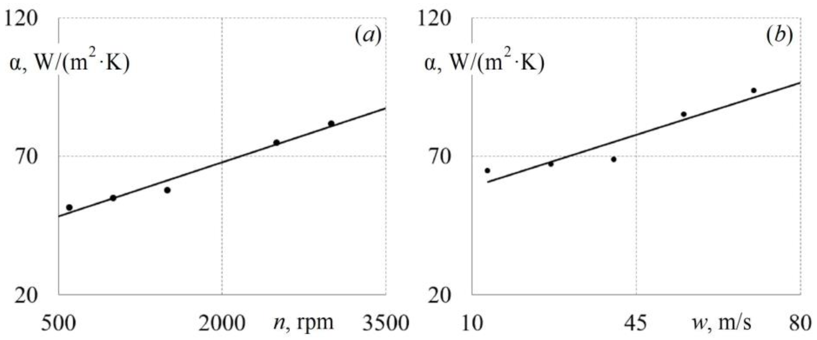
Patterns of changes in the average rate of heat transfer of pulsating flows in the inlet pipeline from the operation factors of the piston engine model are shown in
Figure 7. The average speed w in the intake pipeline was determined for the corresponding crankshaft speed
n in the function α =
f (
w). For example,
w ≈ 11.5 m/s corresponds to
n ≈ 600 rpm;
w ≈ 75 m/s corresponds to
n ≈ 2900 rpm. Engineers commonly use the α =
f (
n) function to design gas exchange systems for reciprocating machines. In turn, specialists usually use the α =
f (
w) function to create mathematical models of processes in the intake and exhaust systems.
From
Figure 7, it can be seen that a change in the average heat-transfer coefficient α of pulsating air flows in the inlet pipeline is linear. There is an increase in α with an increase in the frequency of rotation of the crankshaft (and the average flow rate in the intake system). The data obtained are in good agreement with the articles [
9,
10]. An increase in the shaft rotation frequency (average flow velocity in the inlet pipeline) causes a monotonous increase in the heat transfer intensity.
The dependence α =
f (
n) for the inlet pipeline is described by the following mathematical expression with an error of no more than 2.5%:
This linear equation is valid for values of n ranging from 600 to 3000 rpm and for the cylinder and intake system geometries presented above. Equation (3) can be applied in engineering calculations to assess the level of heating of the working medium during the intake process and thermal stresses for the intake system parts.
The dependence α =
f (
w) for the inlet pipeline is described by the following mathematical equation with an error of no more than 9.8%:
This equation is valid for w values in the range of 5 m/s to 75 m/s and for the cylinder and intake system geometries presented above. Equation (4) is convenient to use for creating or adjusting mathematical models for calculating the rate of heat transfer in gas-dynamic systems, the configuration of which is typical of reciprocating machines.
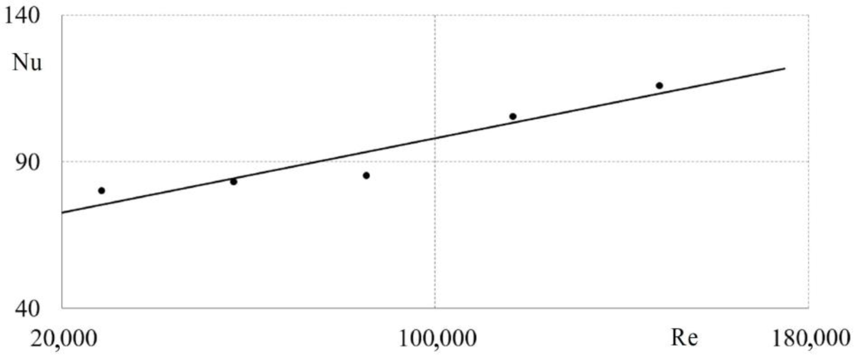
The rate of heat transfer of pulsating air flows in the intake system of a piston machine is presented in a dimensionless form in
Figure 8, i.e., in the form of dependence Nu =
f (Re). It is convenient to use such dependencies when creating mathematical models in specialist software applications.
Figure 8 shows that the dimensionless dependence retains the physical regularities obtained earlier. Thus, with an increase in the Reynolds number, the Nusselt number monotonously (linearly) increases. The dependence Nu =
f (Re) for the inlet pipeline can be mathematically described in the form as follows (error not more than 9.9%):
This equation is applicable for Re values from 20,000 to 160,000 and for the cylinder and intake system geometries presented above. Equation (5) can be used to create new mathematical models of gas dynamic systems, as well as to verify and improve the accuracy of existing mathematical models.
4. Unsteady Heat Transfer in the Exhaust System
A change in the local heat-transfer coefficient of pulsating flows in the outlet pipeline for a full cycle of a piston engine (i.e., for 720 degrees of crankshaft rotation) at various crankshaft speeds and for various initial pressures in the cylinder is shown in
Figure 9. A complete engine cycle takes two revolutions of the crankshaft (720 degrees). The exhaust process (cylinder cleaning) is carried out once from the opening of the exhaust valve to its closing. Then the full cycle repeats again. The movement of gas in the outlet pipeline is carried out only during the exhaust process. Accordingly, the heat transfer rate is also determined for the valve open period.
Figure 9 shows that an intense change (increase) in the local heat-transfer coefficient begins immediately after opening the outlet valve. This is due to the beginning of the gas flow in the outlet pipeline. At the same time, the values of the local heat-transfer coefficient do not become equal to zero after the outlet valve is closed. A change in α
x stabilizes in the region of 540 degrees of the angle of rotation of the crankshaft. It should be noted that the crankshaft speed does not significantly affect the maximum values of the local heat-transfer coefficient (differences are 10–17%). However, the frequency of the crankshaft rotation leads to a shift of the maximum α
x towards larger values of the crankshaft rotation angle. The dynamics of the process become easier as the control section moves away from the exhaust port in the head of the model engine block.
To assess the dynamic pattern of changes in the local heat-transfer coefficient in the outlet pipeline, graphs of the spectrum amplitudes for the function α
x =
f (φ) were obtained (
Figure 10). At the same time, it is known that gas-dynamic conditions (mode of operation) have a significant impact on the patterns of change in the rate of heat transfer [
41].
From
Figure 10, it can be seen that the first significant frequency of the spectrum corresponds to the rotational speed of the test camshaft: 5 Hz for
n = 300 rpm, 12.5 Hz for
n = 750 rpm, and 25 Hz for
n = 1500 rpm. The first significant amplitude is always the largest and is determined by the camshaft speed. With an increase in the pulsation frequency
f, a non-linear decrease in the amplitudes
Aα takes place. In this case, at
n = 300 rpm, the significant frequencies of the spectrum extend up to 170 Hz, and at
n = 1500 rpm, up to 250 Hz. It should be noted that the pulsation amplitudes at a camshaft speed of
n = 300 rpm have higher values than for
n = 750 rpm and
n = 1500 rpm. Consequently, it can be concluded that with an increase in the crankshaft speed, the process dynamics decrease (stabilize). It should also be noted that significant frequencies have a multiplicity equal to the value of the first significant frequency for the corresponding test bench operation mode (5, 12.5, and 25 Hz, respectively).
As a result of experimental data approximation, obtained were equations for calculating instantaneous local heat-transfer coefficients in a dimensionless form with an error of 9.3%. An approximation of the least squares method was carried out. It should be noted that in order to simplify the form of the calculation equation, the dependence αx = f (φ) was divided into two sections, the rise section I (150° < φ < 290°) and the decline section II (290° < φ < 430°). This equation is valid for air and flue gases since their thermophysical properties are close to each other. The score equations for calculating αx, W/(m2∙K) in the outlet pipeline are as follows:
- –
For the ascent stage I (150° < φ < 290°):
- –
For the drop-down stage II (290° < φ < 430°):
where
is the local Nusselt number for the ascent stage (I);
is the local Nusselt number for the drop-down stage (II); β =
po/
pb is the pressure ratio; β
c is the critical pressure ratio (β
c = 0.546); α
x is the local heat-transfer coefficient, W/(m
2·K); d—pipeline diameter, m; λ
t is the gas thermal conductivity coefficient, W/(m
2·K); φ is the crankshaft rotation angle, deg. (170° < φ < 430°); φ
max is the maximum crankshaft rotation angle, deg. (φ
max = 720°);
n is the crankshaft speed, rpm (1000 <
n < 3000);
nmax is the maximum crankshaft speed, rpm (
nmax = 3000 rpm);
lx is the distance from the window in the block head to the control section, m (0.02 <
lx < 0.3);
lmax is the length of the outlet pipeline, m (
lmax = 0.3 m);
po—atmospheric pressure, kPa;
pb is the initial overpressure in the cylinder, kPa; Pr is the Prandtl number.
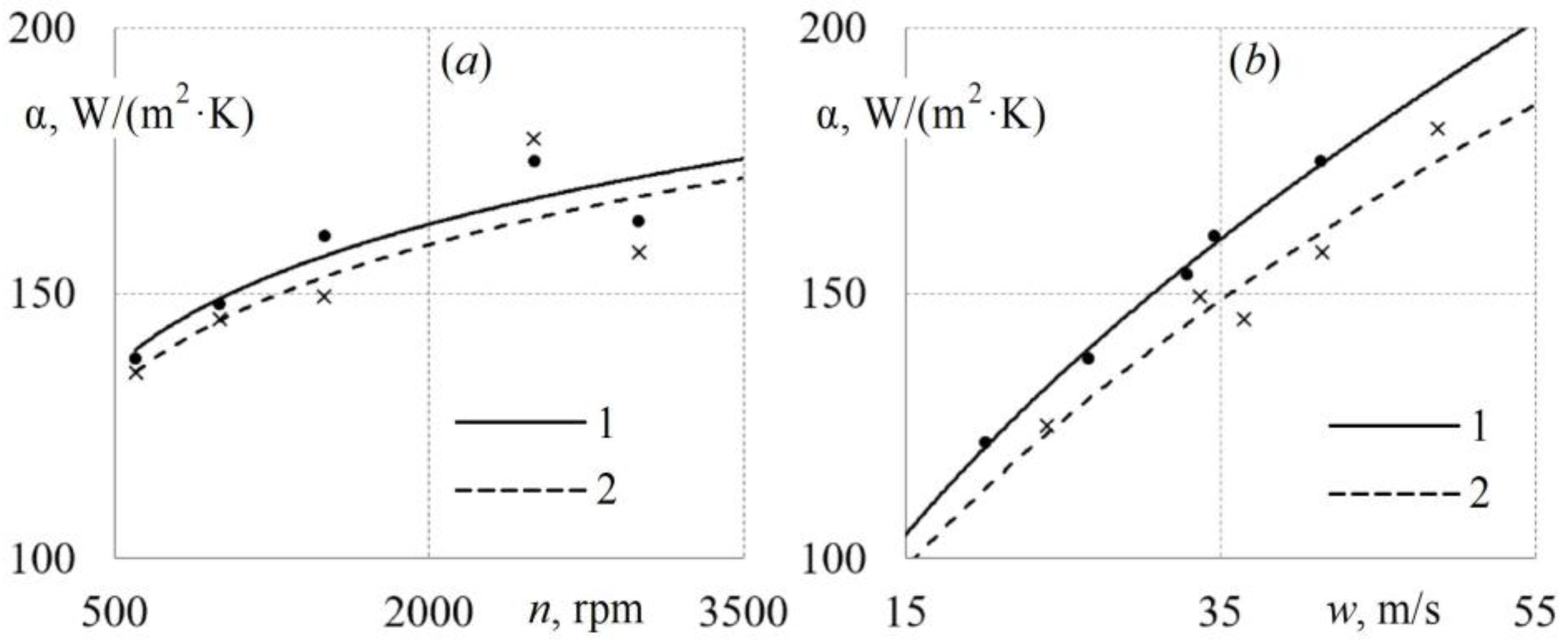
Patterns of changes in the average rate of heat transfer of pulsating flows in the outlet pipeline from physical and operation factors of the piston machine model are shown in
Figure 11.
Figure 11 shows that a change in the average heat-transfer coefficient α of pulsating air flows in the outlet pipeline is non-linear. The pattern of change in the average heat-transfer coefficient in the outlet pipeline is well described by a degree function. There is an increase in α with an increase in the crankshaft rotation frequency (and the average flow rate in the intake system). The data obtained are consistent with the results from the articles [
23,
25].
The dependence α =
f (
n) for the outlet pipeline is described by the following mathematical expression with an error of no more than 12.1%:
This linear equation is valid for values of n ranging from 600 to 3000 rpm, for values of initial cylinder pressure pb from 0.05 to 0.2 MPa, and for the geometrical dimensions of the cylinder and intake system presented above. Equation (8) can be useful in engineering calculations for estimating the level of thermal pressure of exhaust gases and thermal stresses for parts and assemblies of the exhaust system.
The dependence α =
f (
w) for the inlet pipeline is described by the following mathematical equation with an error of no more than 2.6%:
This equation is valid for values of w in the range from 15 m/s to 55 m/s, for values of the initial pressure in the cylinder pb from 0.05 to 0.2 MPa, and for the geometric dimensions of the cylinder and intake system presented above. Equation (9) is convenient to use for creating or adjusting mathematical models for calculating the rate of exhaust gas heat transfer in exhaust systems and turbocharging systems for reciprocating machines of various profiles.
It is known that detailed data on the intensity of heat transfer in the outlet pipeline are necessary for the development of various technical devices and heat exchangers for using the energy of exhaust gases [
42,
43]. These measures are aimed at increasing the efficiency of reciprocating engines.
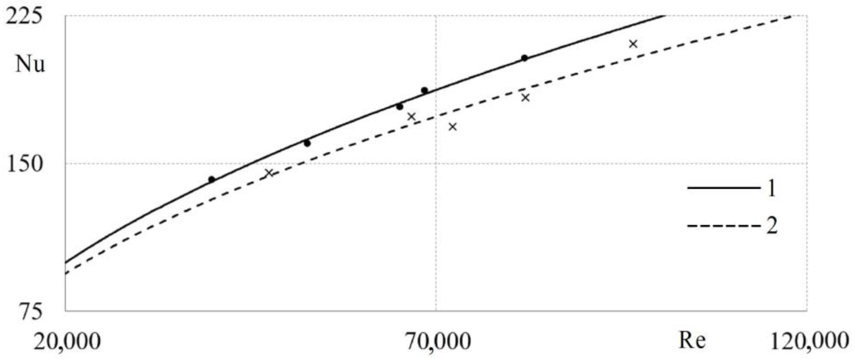
The rate of heat transfer of pulsating air flows in the exhaust system of a reciprocating machine is presented in a dimensionless form in
Figure 12, i.e., in the form of dependence Nu =
f (Re). This type of equation is convenient to use when creating mathematical models for modeling heat transfer in specialist software applications.
The dependence Nu =
f (Re) for the outlet pipeline can be mathematically described in the form (error not more than 3.4%) as follows:
This equation is applicable for Re values from 35,000 to 100,000, for initial cylinder pressures pb from 0.05 to 0.2 MPa, and for the cylinder and intake system geometries presented above. Equation (10) can be used to create mathematical models of exhaust systems, as well as to adjust and improve the accuracy of existing mathematical models of gas dynamic systems of reciprocating machines.
Thus, the obtained mathematical dependences can be used to describe the rate of heat transfer in the gas exchange systems of reciprocating machines in both engineering methods and mathematical models in specialist software applications. The data can also be used to tune machine learning algorithms and AI-based control systems.
