Abstract
In this work, the solidification and cooling process of an irregularly shaped splat is modeled using the network simulation method. The procedure for its implementation, which uses the finite difference method and optimized circuit analysis algorithms, allows the precise incorporation and assessment of the effect of certain conditions in the thermal process, offering its specificity and high performance in numerical simulation. It should be noted, on the one hand, that the geometry used for the simulation has been obtained from experimental splat data visualized using an electron microscope and, on the other hand, that the model implements both the phase change phenomenon and the variability of the material properties with temperature. Finally, the study of the physical behavior of the problem is carried out using the mathematical technique of nondimensionalization, allowing the interpretation of the results obtained by simulation, where the formation of horizontal bars and columns that maintain the structure of the splat while the solidification process is taking place stands out. It is worth highlighting the obtaining, among others, of two monomials. The first relates the phenomenon of radiation to conduction and is equivalent to the Nusselt number with convection, and the second relates the solidification time with the Stefan number.
Keywords:
network simulation method; nondimensionalization; ceramic coatings; phase change; differential equations; engineering problem MSC:
00A73; 00A69; 00A79; 00A72
1. Introduction
One technique for creating a protective layer consists of a thermal spraying of small molten particles of ceramics, alloys or metals. When the particles hit the substrate, they solidify and form splats, thin and dense sheets, whose shape depends on many variables such as temperature, size and properties of the sprayed drops, substrate temperature, etc. [1,2,3,4]. The importance of these factors lies in the properties that the splat acquires, that are, adhesion strength, interface stresses, etc. The final form that the splat acquires has been studied in numerous studies [4,5,6,7,8,9,10,11,12,13,14,15].
In this way, it is necessary to achieve a deep understanding of the phenomena involved in the splat creation process, including its cooling and solidification, in order to improve the quality of the final coating [16].
Therefore, one of the main factors involved in the process is the cooling speed, which various works have established to be in a range that covers from 1 to approximately 109 K/s depending on the phase (amorphous, gamma or alpha) or the process [1,17,18,19,20,21]. Various analytical models have established their dependence on the latent heat of fusion, the contact between the substrate and the splat, thermal diffusivities, etc. [1,21,22,23,24].
Another factor that influences the cooling rate is the so-called thermal contact resistance that forms between the substrate and the splat. On the other hand, the properties mentioned above, which influence the cooling rate, change with temperature, so to make a more accurate model, it is necessary to include these variations. In addition, it is necessary to include the irregularity that the splat presents in the model [25,26,27,28,29,30,31,32,33].
Therefore, the main objective of this study is twofold. On the one hand, the objective is to create a reliable and accurate network model for the solidification problem based on the network simulation method, which is an evolution of previous models, and which includes splat irregularities and properties variability with temperature. In addition, the model, which will be simulated using the free code NgSpice [34], should allow the study of both the evolution and distribution of temperatures in the splat as well as the cooling rate. The network simulation method, like other methodologies [35,36,37,38,39,40], makes it possible to solve coupled systems of partial differential equations that represent the science or engineering problem to be solved. The importance of this method lies in the fact that if any problem is well defined, it can be solved by following a series of application rules. The creation of the network model will be explained in depth in Section 4.
On the other hand, for a reliable and precise interpretation of the physical phenomena involved in the cooling and solidification process, the mathematical technique of nondimensionalization is used, which can obtain groupings of the variables that influence the process, indicating what weighting they have on the mentioned physical phenomena that take place, and can thus explain the behavior of the splat in its cooling and solidification.
Both the network simulation model and the nondimensionalization technique have demonstrated the effectiveness of their application in numerous engineering problems such as diffusion of chlorides, chemical reactors, soil consolidation, etc. [41,42,43,44]. Finally, there are several main contributions of this paper. On the one hand, the implemented network model encompasses both the phase change and the variability of the material properties with temperature, implying a change in the model to implement both phenomena. In addition, the splat shape obtained by electron microscopy is modeled. On the other hand, the application of the nondimensionalization technique has led to the appearance of, among others, two monomials. The first relates the phenomenon of radiation to conduction and is equivalent to the Nusselt number with convection, and the second relates the Stefan number to the time it takes for the phase change to occur. Thus, the combination of both methodologies allows us to interpret the results obtained as the appearance of horizontal bars and columns that maintain the splat structure while the solidification process is taking place.
2. Splat Morphology
Before employing the mathematical model to calculate the evolution of temperatures during the solidification and cooling process of the splat, we must know its geometry. For this, numerous splat sprays have been carried out under different thermal spraying conditions, obtaining similar geometries to those shown in the example below.
In a schematic way, the thermal spray is an ionized plasma gas produced using inert gases heated up by a DC electric arc. The sprayed material ceramic drops, which come from ceramic powder carried in an inert gas stream into the plasma jet, are propelled towards the substrate. The thermal spray system used was the SURFACE ONE from Oerlikon Metco, Switzerland, which includes a robot IRB 2600 of ABB, Switzerland. As González et al. [45] explain, the parameters that control the spray process are electric current and Ar/H2 gas flow.
The powder used in this work was Metco 450NS −90 + 45 µm, which means that its size distribution is such that 90% of the particles have a size equal to or less than 45 µm. Its composition is Ni5Al. A suitable torch speed and a low powder flow were chosen in order to obtain isolated splats.
Once the splats had been formed, they were visualized using an electronic microscope with the capacity to perform microscopic sections using a Ga beam. The microscope used was a field emission scanning electron microscope from Carl Zeiss Microscopy GmbH, Germany. The spraying parameters used for the figures shown below were 450, 550 and 650 A for the supply current, and 6.5, 9.5 and 12 slpm for the H2 flow.
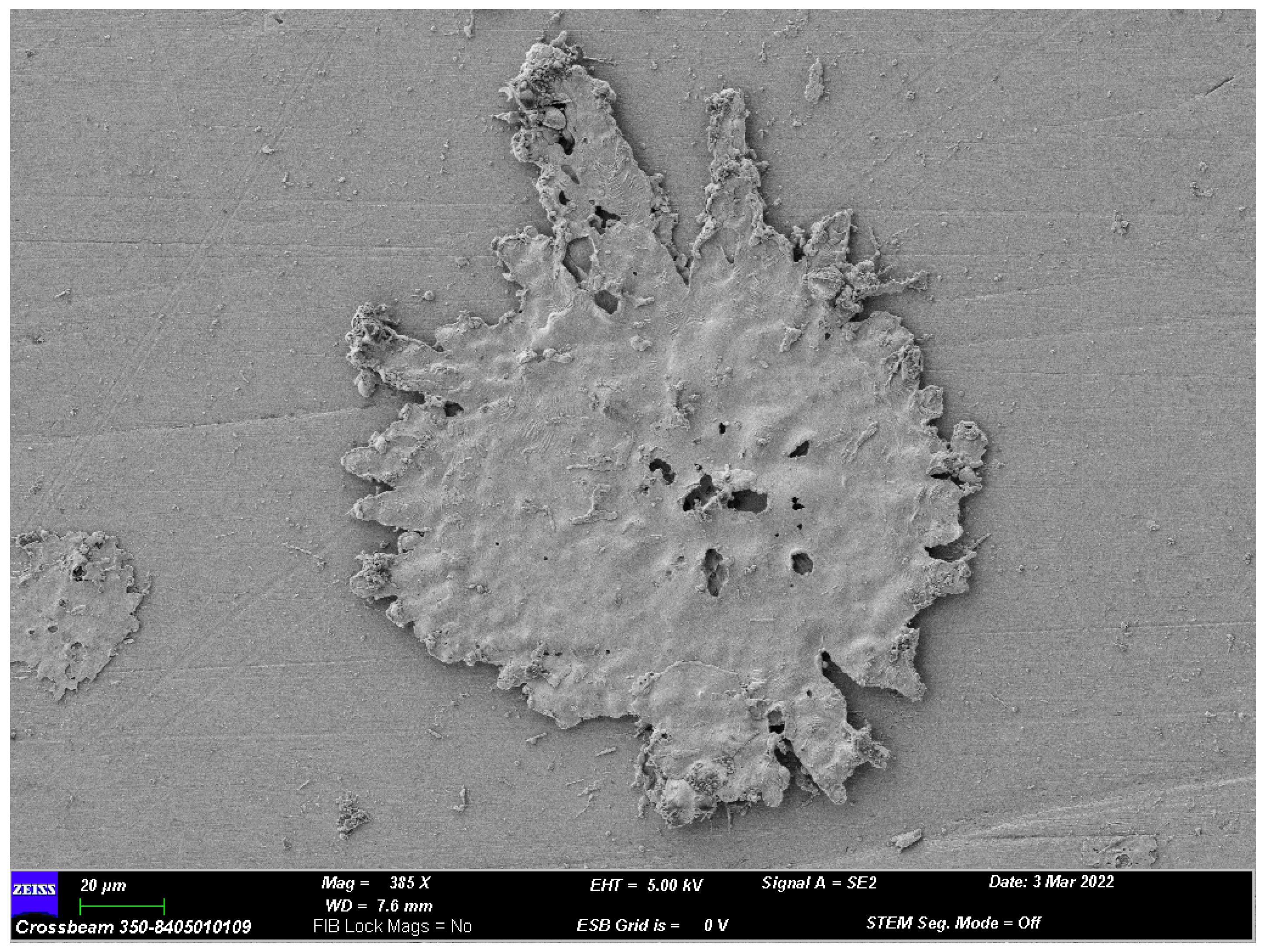
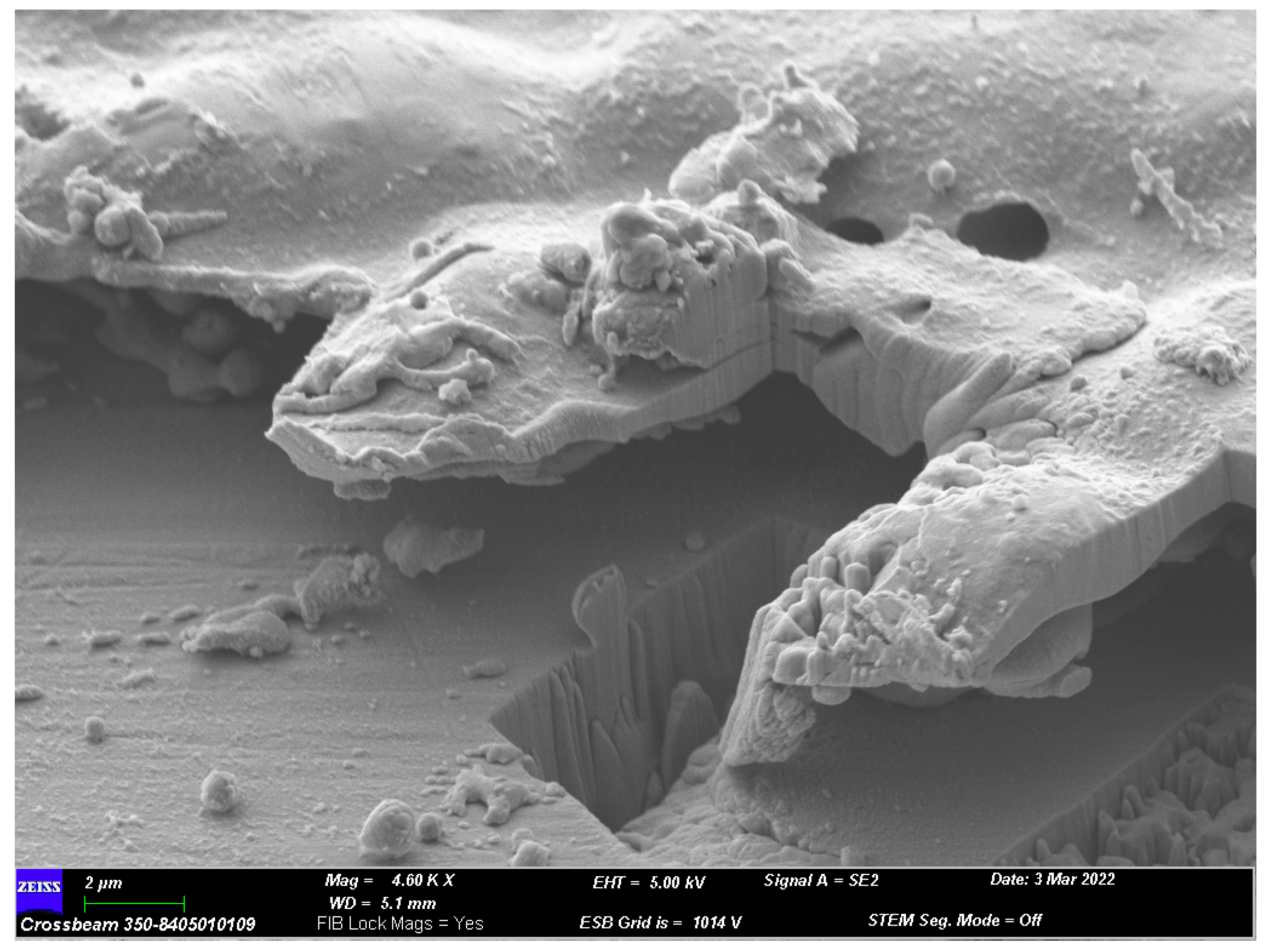
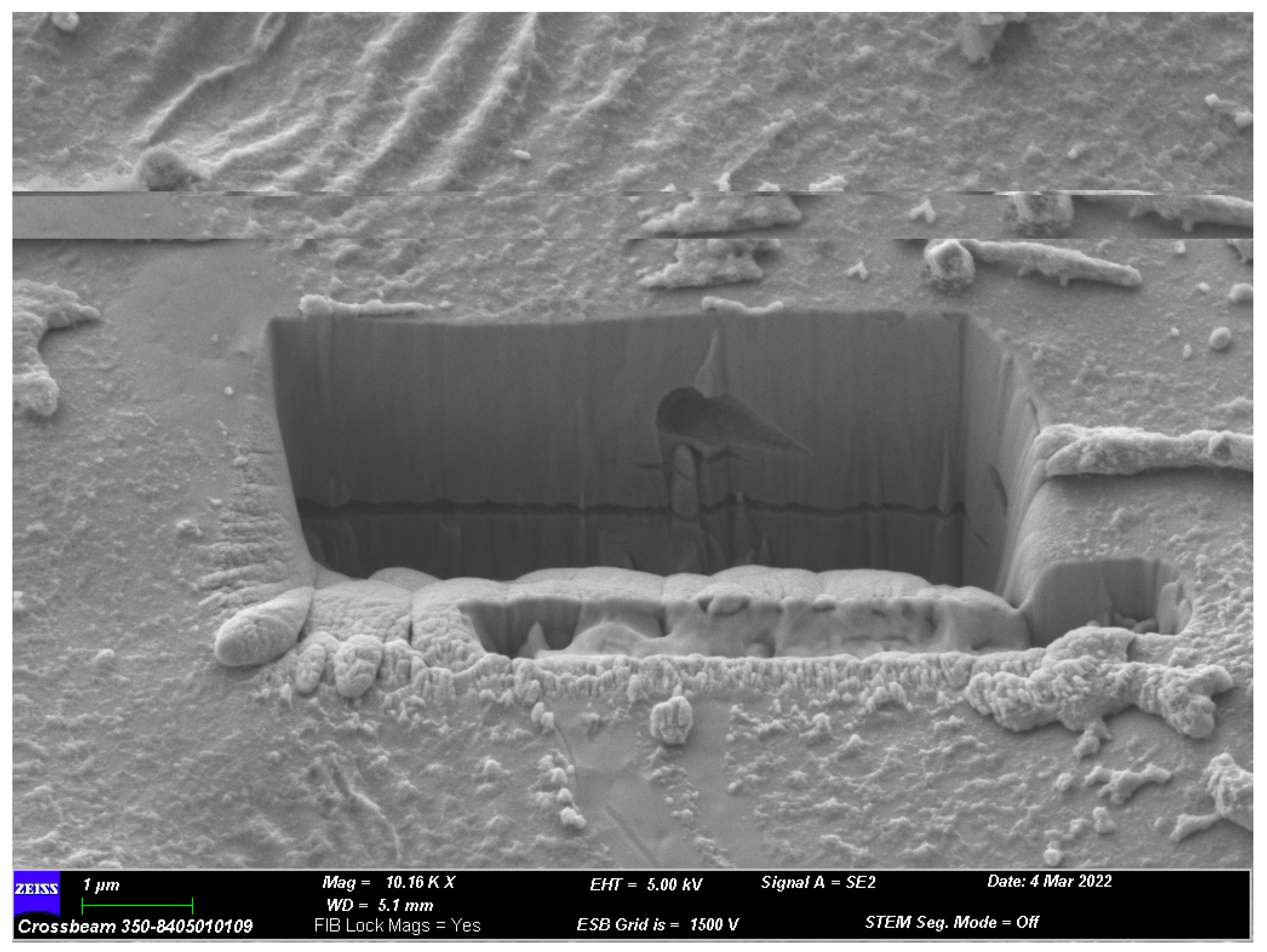
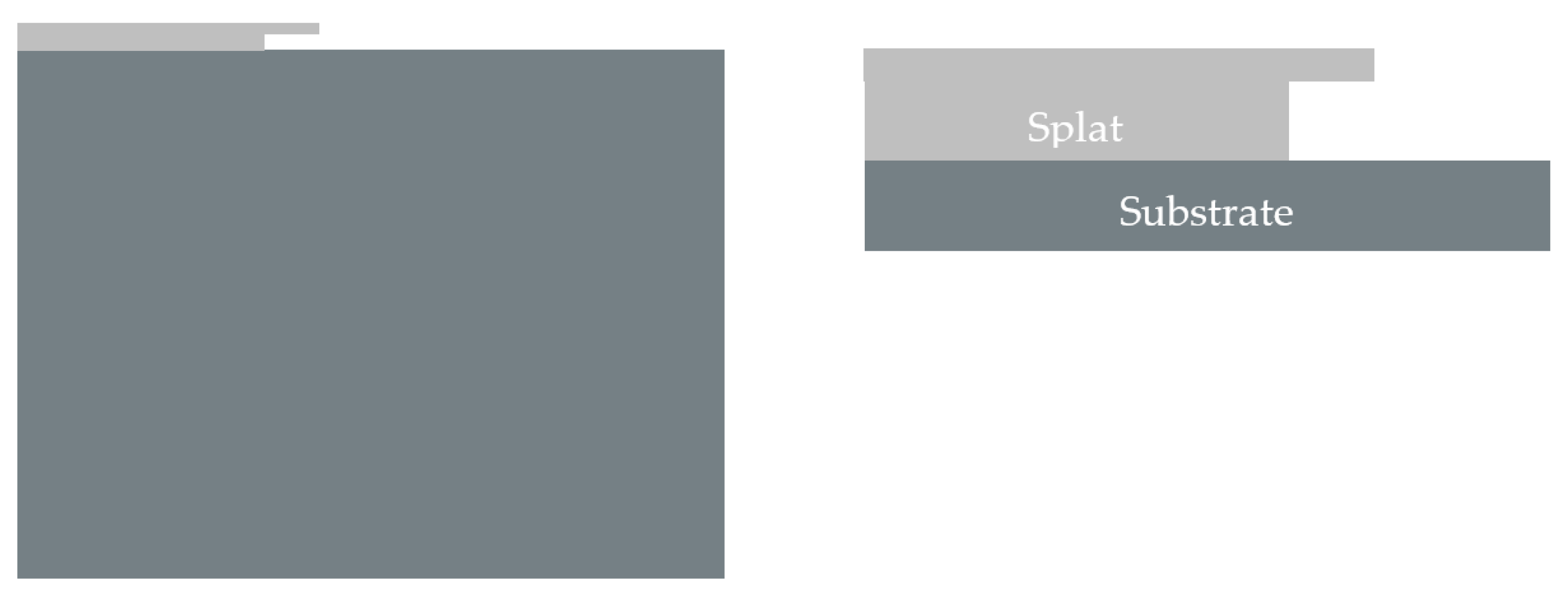
The splat obtained using 650 A and 6.5 slpm is shown in Figure 1. Figure 2 shows the way in which the edge of the splat has peeled off from the substrate. Figure 3 shows the section of the splat in the central zone. From this information, the diagram of the model represented in Figure 4 has been generated. This figure represents a cross-section of the splat, taking the dimensions of height and length from its centre and including the cantilever, as well as the cross-section of the substrate. Finally, Figure 5 shows the splat dimensions with the cantilever, where Lg and H are the splat length and height, respectively. These dimensions are the ones that will be used for the mathematical modeling and for its subsequent simulation.
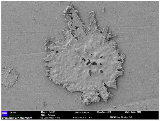
Figure 1.
Splat obtained using 650 A and 6.5 slpm.
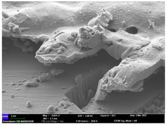
Figure 2.
Section of the splat edge in Figure 1.
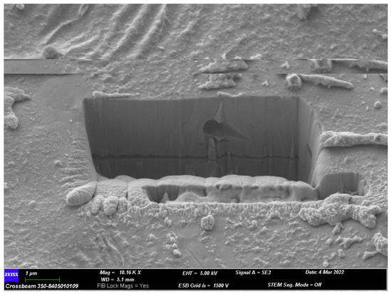
Figure 3.
Section of the inside of the splat in Figure 1.
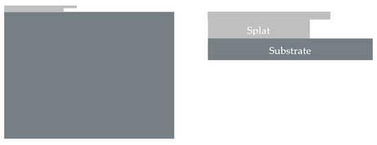
Figure 4.
Cross-section of the splat taken from its centre with the cantilever (light grey) and substrate (dark grey). Zoom on the splat.

Figure 5.
Splat dimensions with cantilever.
3. Mathematical Model
The system of coupled differential heat transfer equations for a homogeneous, constant, axisymmetric and isotropic domain, which absorbs or emits heat, is [1,46,47]:
where T is the temperature in K, D is the thermal diffusivity in m2/s, x and z indicates the spatial coordinates, and finally, the subscripts s and l denote the solid or liquid phase, respectively. In addition, k is the thermal conductivity in J/m K, cp is the specific heat in J/K kg and ρ is the density in kg/m3. On the other hand, another phenomenon involved is the phase change from liquid to solid that is taking place in the splat. Because when this change occurs, the material properties vary or the temperature remains constant while the change is taking place, it is necessary to implement where this change is taking place in the mathematical model. To determine the position of these zones, Stefan’s equation was used, which is given by:
where n is the norm to the surface and un is the displacement interface. An alternative expression for Equation (4) is to assume that an infinitesimal volume of liquid changes state, in this case from liquid to solid, when it reaches the temperature of solidification while latent heat is transferred [1]:
where Ω is the volume in m3 and L is the latent heat of fusion in J/Kg. When the equations are implemented in the model to be simulated, the splat can be studied as a rectangle (Figure 1) with a typical cantilever that appears in this type of splat, where the axis of symmetry is considered adiabatic, with the upper and lateral limit as radiant and convective:
where h is the heat transfer coefficient in W/m K, Q is the heat in J, σ is the Stefan–Boltzmann constant in W/m2 K4, ε is the emissivity, S is the contact surface with the air in m2, and finally, the subscripts env and splat denote contact with the air and contact with the splat surface, respectively. In addition, the union between the substrate and the splat must be considered due to the change in material and possible discontinuities. That is, heat transfer must be implemented between the area of the splat that is in contact with the substrate and the substrate itself. To implement it, a model similar to Sobolev’s is used, where the heat transfer through the thermal gradient between two adjacent cells, one in the splat and the other in the substrate, and the resistance to the transfer of this energy due to the change in medium are related [19,32,33]:
where hC is the transfer coefficient between the substrate and the splat in W/m K, A is the contact area between the splat and the substrate in m2, and hC is equal to 1/Rth, where Rth is the contact resistance in m K/W. Finally, the subscript subst denotes substratum and splat; subst is the splat area in contact with the substrate.
4. Network Model
The method selected to solve the complex system of equations above is the network simulation method. Both examples and descriptions of the foundations and applicability of the method to science and engineering can be found in descriptions by González-Fernández et al. [48] and Sánchez-Pérez et al. [41,49].
This methodology has been widely applied to different engineering problems such as chloride diffusion, heat transfer, oxidation problems, inverse problems and phase change problems [1,41,43,47,50]. All of the above problems present coupled and nonlinear systems.
However, a summary of the applied methodology will be presented. The network simulation method consists of creating a network of electrical circuits that is equivalent to the mathematical model that represents the physical problem, for which several well-differentiated stages must be followed for the construction of the model:
- In the first place, the relationship between the voltage in the central node and the variable to be studied is established;
- Each sum of the equations is implemented by means of currents that are balanced in a central node. For this, there are different electrical devices with which to implement the addend, such as resistors, current generators, capacitors, batteries, etc.;
- The circuit created must comply with Kirchhoff’s laws.
Once the network model has been built, it is simulated using an electrical circuit simulator such as NgSpice [34].
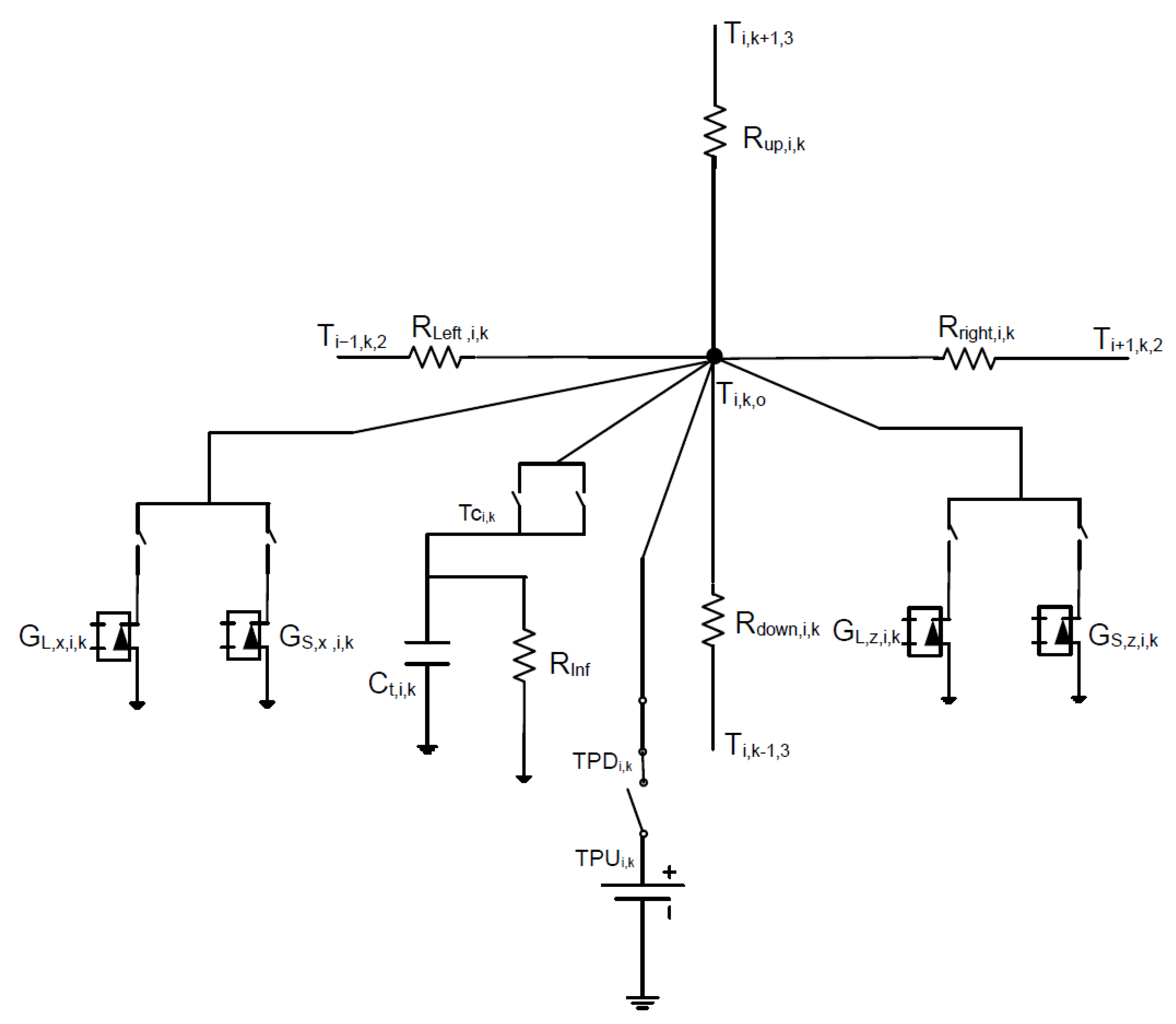
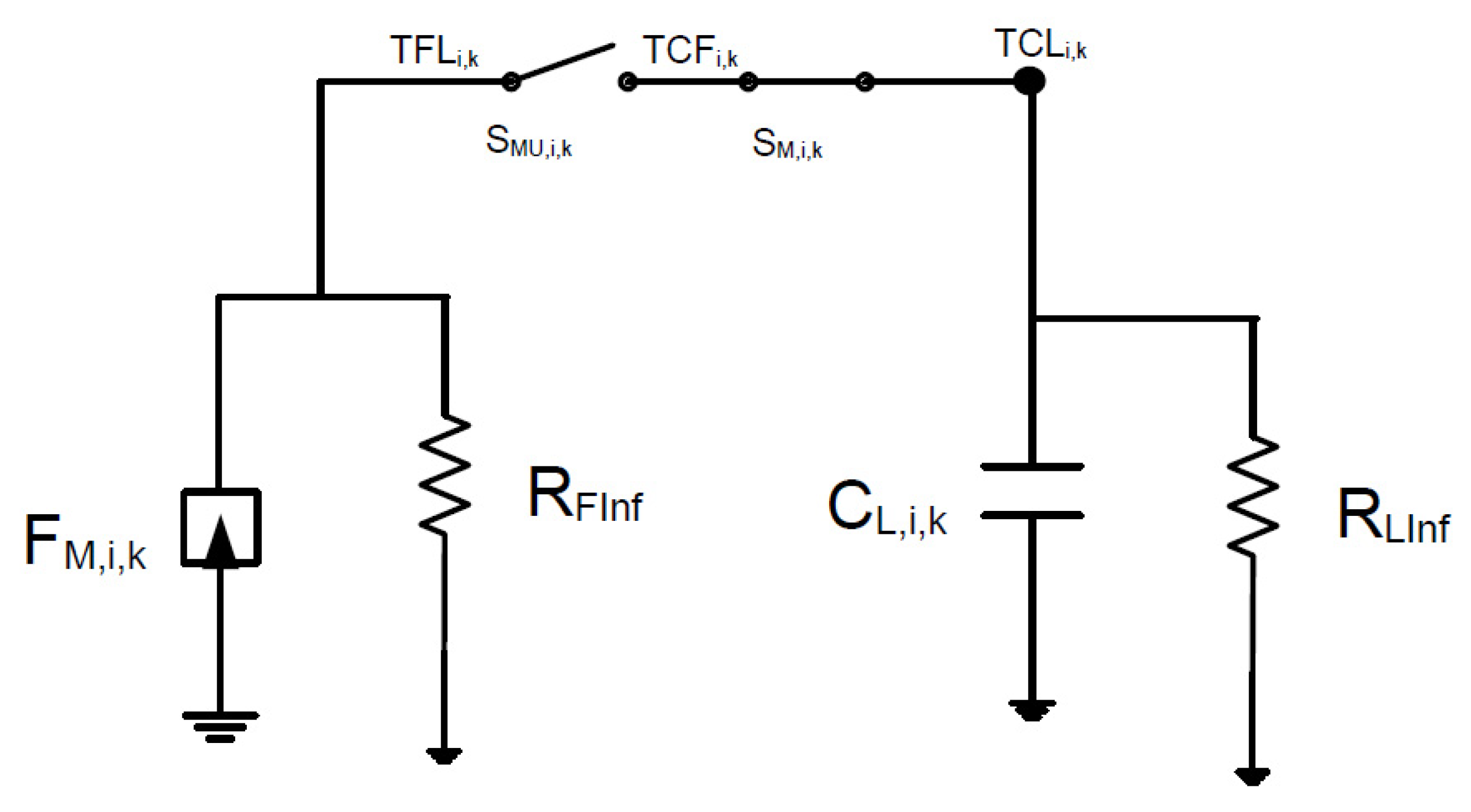
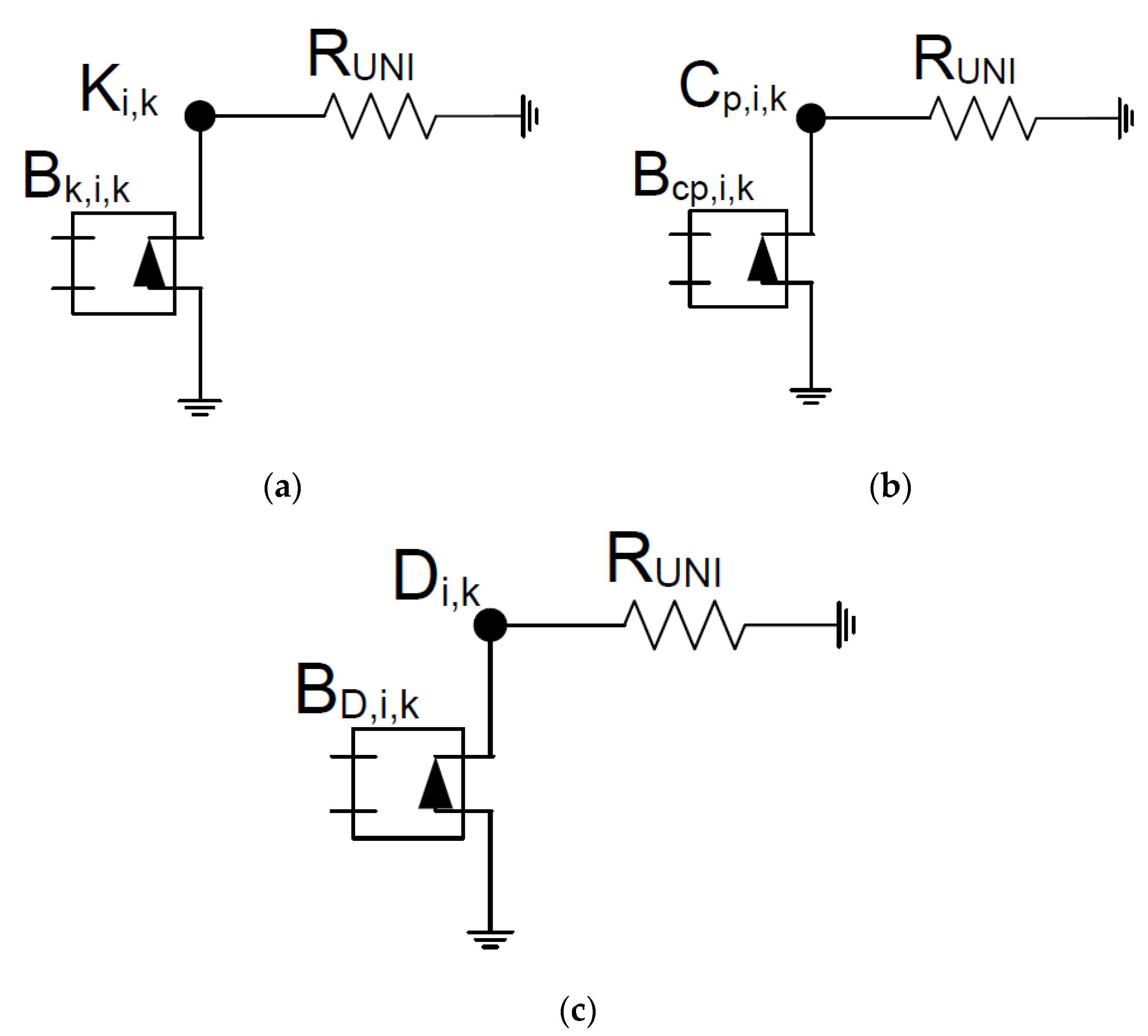
Thus, the network model used to solve the complex problem of solidification is shown, where the first circuit describes the thermal behavior of the splat, that is, the thermal diffusion equations. In order to implement the variability of the properties, that is, of the thermal diffusivity, Equations (1) and (2) have had to be developed, as shown in Equation (9). In this way, the second derivatives are implemented as resistors that include the first addends of Equations (9) and (10) to give stability to the circuit and as current generators, where two values regulated by switches appear, one for the liquid state and another for the solid state. As the value of the first addends in Equations (9) and (10) is the same, it is implemented as two resistors for each addend, where each of them links the central node with the extremes, as shown in Figure 6. The time derivative is implemented as a capacitor with infinite resistance to give stability when the solidification process occurs. Finally, during the phase change, the temperature remains constant with a voltage source, as shown in Figure 6. Equation (5), which regulates the phase change process, is implemented by means of a linear current-controlled current source, switches and a capacitor. Switches are used to start and end the solidification process. The circuit is programmed so that when the unitary value is reached in the capacitor, solidification ends, as shown in Figure 7 [1]. Finally, the variability of the properties is implemented with voltage sources and conditionals typical of the spice code, as shown in Figure 8.
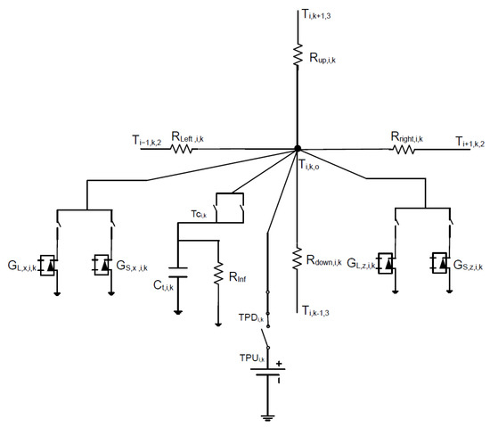
Figure 6.
Network model for the thermal diffusion equations.
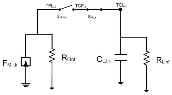
Figure 7.
Network model for the phase change equation.
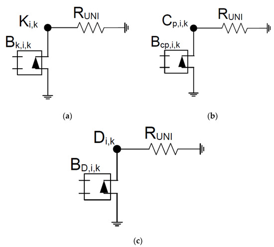
Figure 8.
Circuit to implement the variability of properties. (a) Thermal conductivity, (b) specific heat and (c) thermal diffusivity.
5. Nondimensionalization
In this section, a study of the behavior of variables will be carried out through their grouping into dimensionless monomials. For this, a mathematical procedure known as the nondimensionalization technique will be applied where the variables are grouped into monomials that have a physical meaning and that control the problem [44,51]. One of the major difficulties of this technique is the appropriate choice of references to obtain the dimensionless variables, which implies a deep knowledge of the physical phenomena involved. On the other hand, the discrimination technique must also be implemented, which implies, among other things, anisotropy. Despite the fact that in this problem some properties have values that vary with temperature, for the application of the technique it will be assumed that they take constant values, an assumption that will be justified below, thus facilitating its application.
Firstly, the dimensionless variables are established, which due to the correct choice of references are in the range of [0–1], Equation (11).
where Tenv is the ambient temperature in K, Ti is the initial temperature in K, Lg is the length in m, H is the height in m, and τ is the time at which the problem reaches a steady state in s. Obviously, because of the type of problem described in the previous sections, the splat is cooling down.
Once the dimensionless variables have been established, they are introduced into Equations (1) or (2) to obtain dimensionless equations.
Because dimensionless variables by definition are of the unit order of magnitude, it is assumed that their changes are also of this order of magnitude. Thus, the dimensionless equation gives three coefficients, shown in square brackets, and among them, two monomials which must be of the unit order of magnitude, as shown in Equation (14). As expected, the monomials that will be formed do not depend on the temperature variation.
where the monomial π1 relates the diffusive phenomena and the time to reach the steady state, and the monomial π2 relates the geometric relation of the splat.
Given that both convection and radiation phenomena occur in the process, if the dimensionless technique is applied to Equations (6) and (7), and knowing that , and the approximation , two coefficients appear for each equation that are grouped into the monomials π3 and π4.
Because the unknown τ appears in all three monomials, and it is interesting that it is found in only one of them, two new monomials without this unknown can be obtained by simple mathematical operations between the monomials.
It should be noted that the monomial π1 is the well-known Fourier number, and π5 is the Nusselt number, Nu [52]. Similarly, π6 is a dimensionless number similar to the Nusselt number, but which relates radiation and conduction phenomena.
Finally, the time in which the stationary state is reached, unknown τ, can be obtained by applying the π-theorem, π1 = Ψ (π2, π5, π6).
where Ψ is an unknown function.
On the other hand, this technique must also be applied to Stefan’s equation, which indicates the position at which solidification is occurring. Obviously, the time in which the solidification process takes place is different from that of the cooling process. Moreover, the solidification time influences the cooling time because before the end of this process, solidification has to take place. In this way, a new characteristic time must be introduced, which, in this case, is associated with the solidification process. Thus, the dimensionless variables for this process are the following:
where TM is melting temperature, Ti is the initial temperature and is the time in which solidification has finished. By introducing the above dimensionless variables into Equation (4), its dimensionless form can be obtained.
The equation provides six coefficients from which two monomials emerge, instead of five, because three of them are a combination of the other two. The first relates the change in thermal conductivity from liquid to solid and the geometrical relationship, and the second relates the solidification time to the geometrical variables of the problem and the material properties.
Finally, the time in which solidification has finished, unknown τs, can be obtained by applying the π-theorem, π8 = Ψ′ (π7).
Note that this expression includes Stefan’s number, [53,54]. Consequently, Equation (23) can be rewritten as:
Finally, as a conclusion, the influence of this solidification time on the final time of the process should be highlighted. Furthermore, it must be taken into account that the properties of materials vary with temperature, and the expression that defines them must be included in the monomials that have been obtained.
As previously stated, the nondimensionalization technique applied in this work is used to establish the behavior of the variables by grouping them into monomials and to be able to later interpret the results obtained from the simulation. Therefore, an in-depth study of the monomials and relations obtained in this work and the possibility of obtaining universal solutions remains for future work.
6. Material Properties
The material that solidified was a splat of Ni5Al on an AISI 1045 steel substrate. The properties of the materials and starting parameters are shown in Table 1, Table 2, Table 3, Table 4, Table 5 and Table 6 [55].

Table 1.
Ni5Al properties.

Table 2.
Specific heat of Ni5Al as a function of temperature.

Table 3.
Thermal conductivity of Ni5Al as a function of temperature.

Table 4.
AISI 1045 steel properties.

Table 5.
Specific heat of AISI 1045 steel as a function of temperature.

Table 6.
Thermal conductivity of AISI 1045 steel as a function of temperature.
7. Results
After implementing the network model corresponding to the equations in Section 3, the results of the simulations are shown.
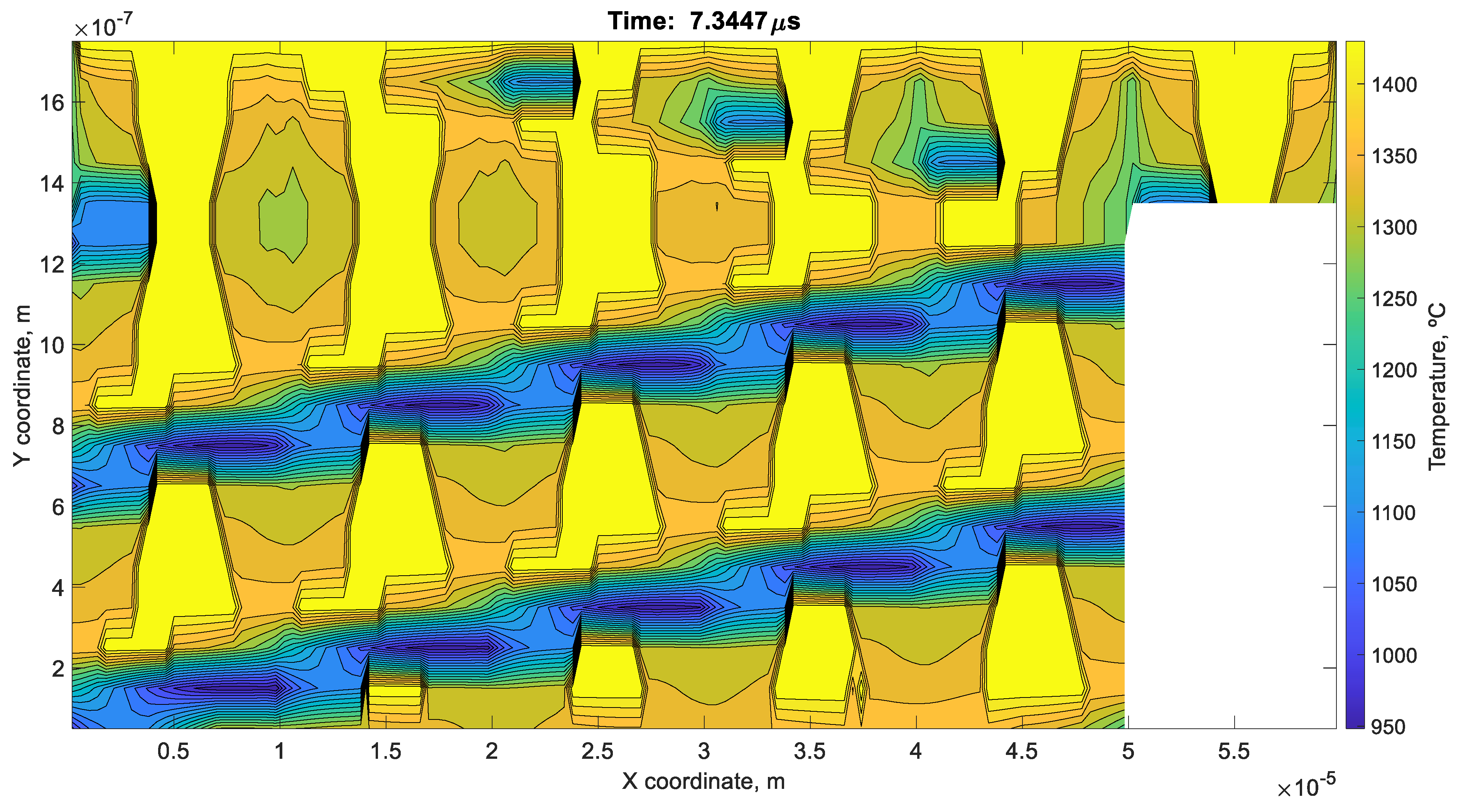
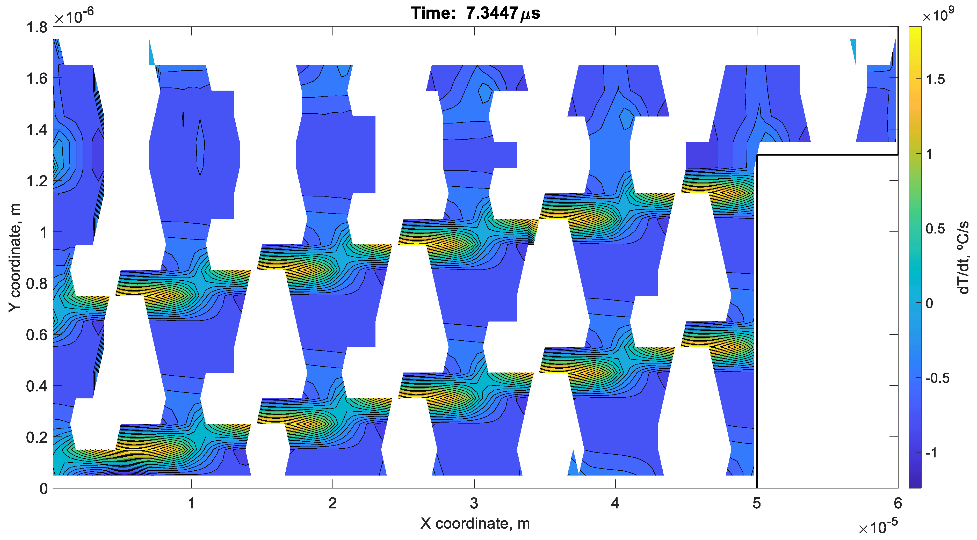
Figure 9 shows the temperature distribution at 7.3447 μs where three zones can be identified. In the first, the blue zone, solidification has already occurred, and it was the first to solidify. As can be seen, horizontal bars are formed that maintain the splat integrity. Next, in the second zone, mainly orange, columns are being formed that maintain the previous bars and therefore the splat structure. Finally, in the last zone, which is yellow in color, solidification is taking place. This is corroborated by Figure 10, which shows the cooling rate of the splat. As can be seen, the white areas have zero velocity, i.e., they neither cool down nor heat up, as the temperature remains constant during the solidification process.
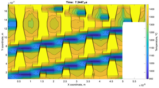
Figure 9.
Temperature distribution at 7.3447 μs.
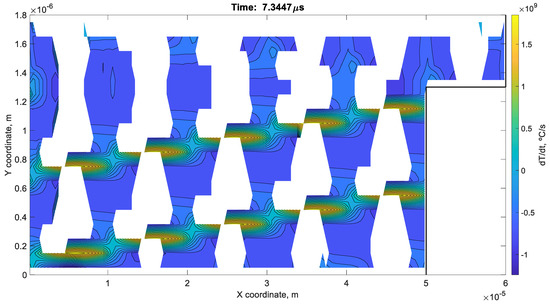
Figure 10.
Cooling speed at 7.3447 μs.
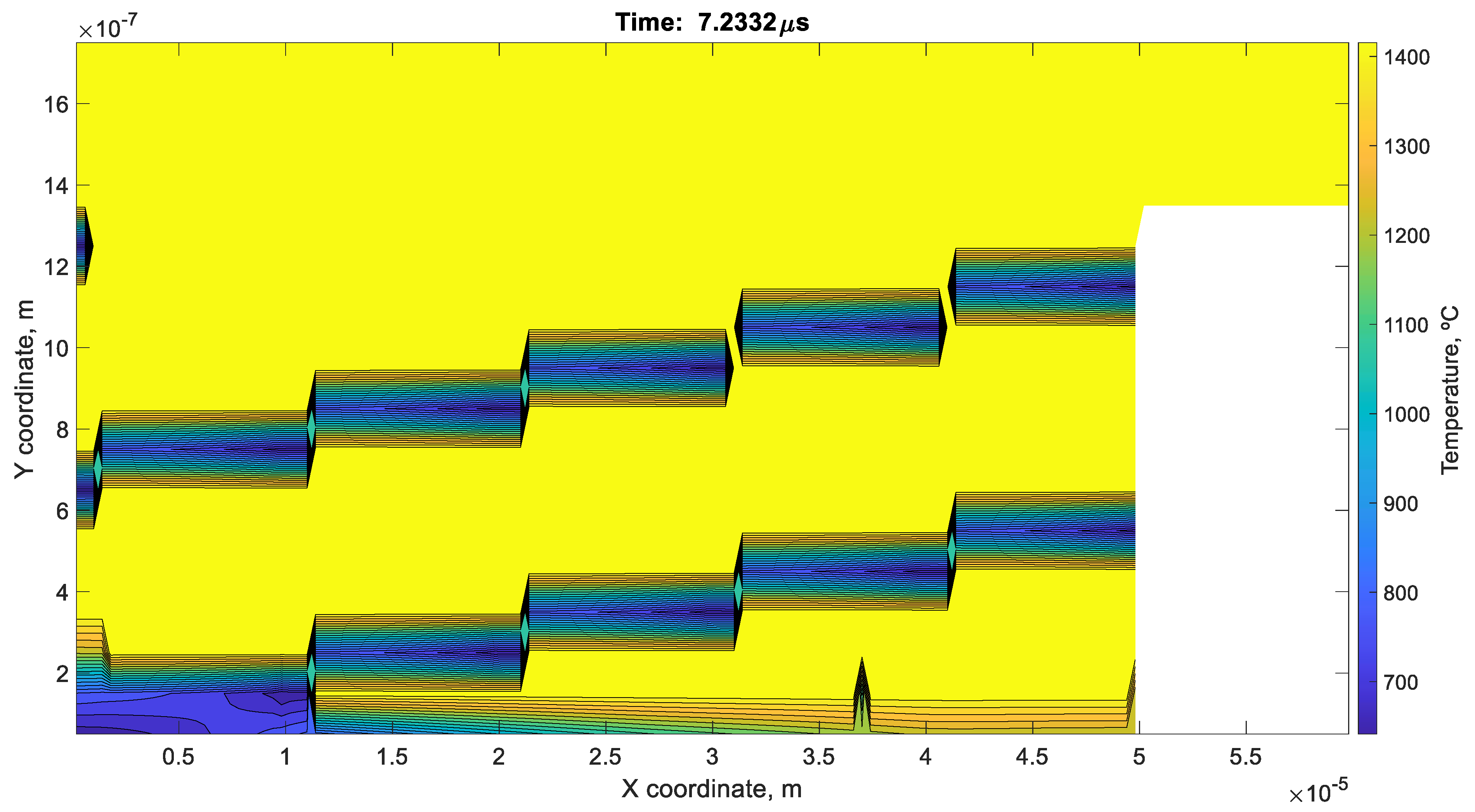
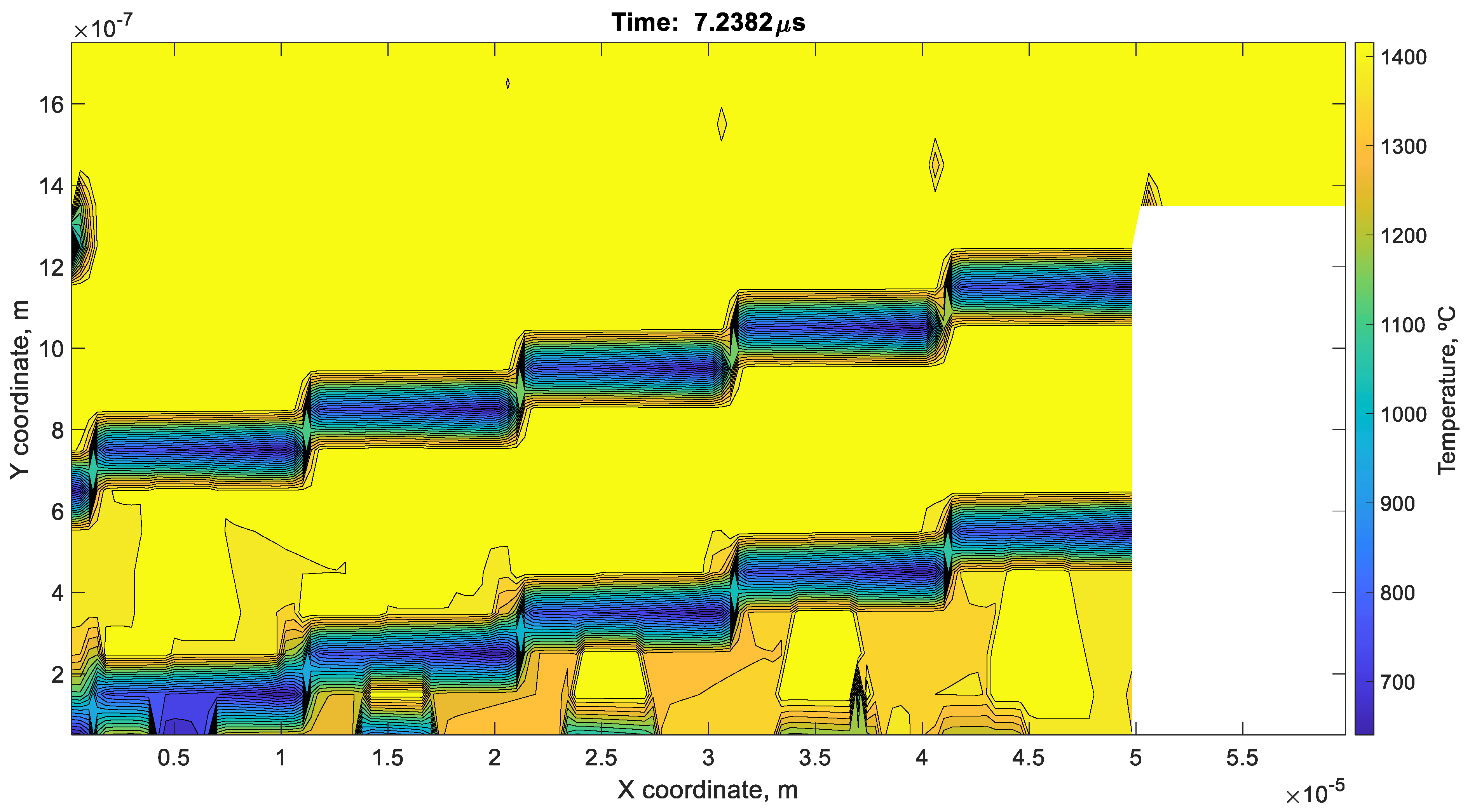
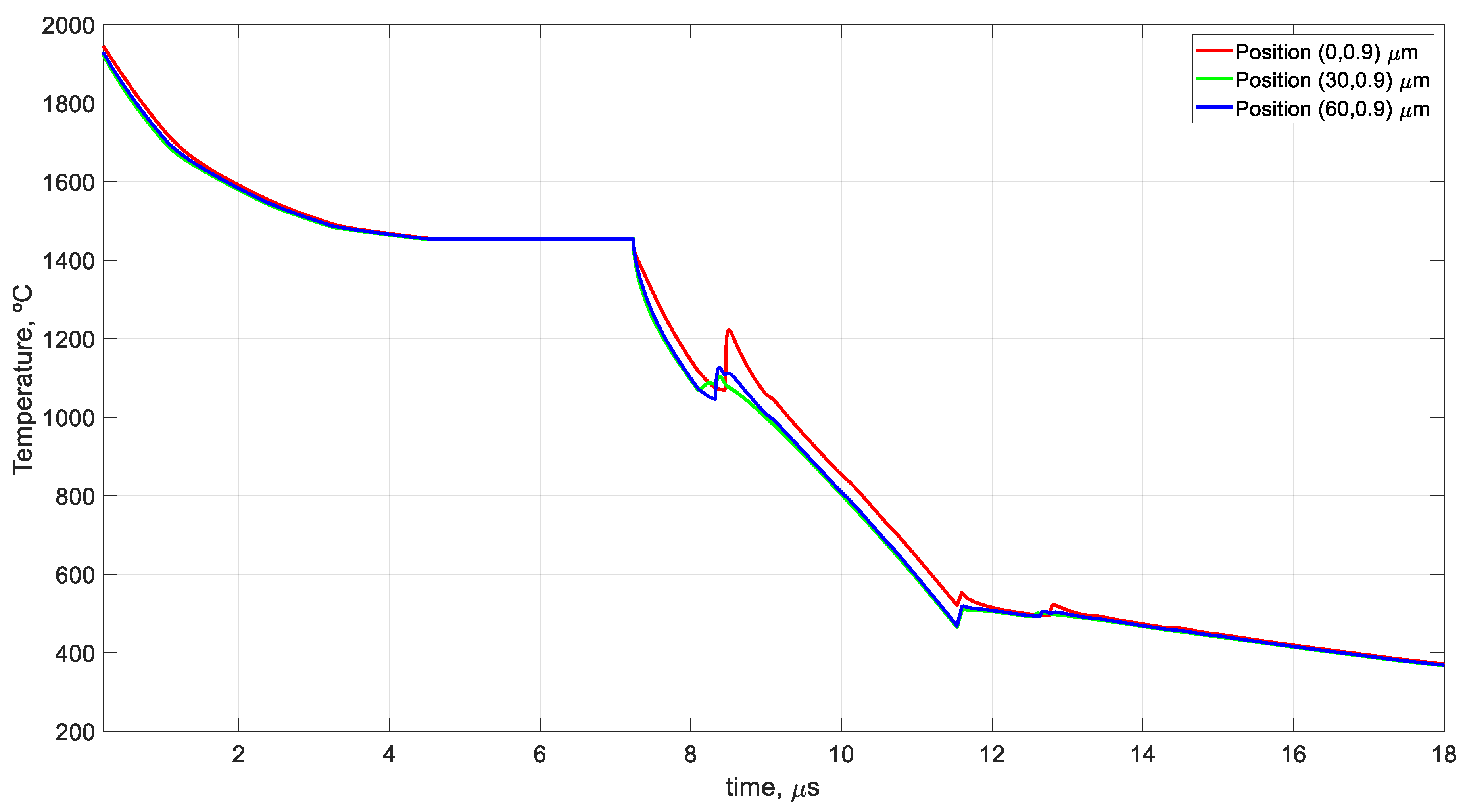
As previously shown in the mathematical analysis of the process by nondimensionalization, the cooling of the splat depends on four dimensionless numbers, the Fourier number, the Nusselt number, one that involves radiation phenomena (similar to the Nusselt number, but with radiation instead of convection phenomenon), and the geometric relationship between the height and width of the splat. The formation of the horizontal bars is due to the fact that the conduction phenomenon (Forurier number) predominates over the radiation and convection phenomena (Nusselt number and radiation monomial) on the vertical axis, together with the horizontal radiation and convection form the aforementioned horizontal bars. This behavior is also justified by the monomial that relates the geometry of the problem, because the width, Lg, is approximately 33 times the height, H. Next, the formation of the columns is due to cooling by conduction, convection and radiation on the vertical axis, with conduction again predominating, because the columns begin to form from the substrate. As already mentioned, the fact that the horizontal bars are formed before the vertical ones is also due to the dimensionless geometric number because the length is much greater than the height. This explains that because the bars and columns are formed first, there are areas that are the last to solidify (yellow areas). On the other hand, expression 24, which is related to the solidification process, corroborates the results and the analysis carried out because through geometric factors and changes in thermal conductivity, it favors the formation of columns through the cooling process by conduction, radiation and convection. Thus, this process can be clearly illustrated in Figure 11 and Figure 12. At 7.2332 μs, the bars that will support the structure have formed and the rest of the splat is in the process of solidification (yellow zone). A total of 5 ns later, the formation of columns begins (7.2382 μs) to be completely formed at 7.3447 μs (Figure 9). Finally, Figure 13 shows the evolution of the temperature at different points of the central axis in the y-coordinate of the splat, where it can be observed how the solidification process occurs practically simultaneously in this axis because it corresponds to the formation of a horizontal bar. It should be noted that after solidification, a rapid cooling of the cell occurs due to the release of energy and the change in the properties of the material. Afterwards, it suffers a temperature rise due to the release of energy in adjacent cells after completing its solidification process. As shown in Figure 13, this phenomenon is more pronounced the deeper the position of the cell as it will receive the energy released from a larger number of cells.
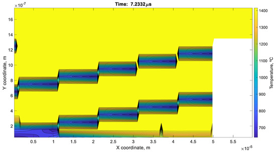
Figure 11.
Temperature distribution at 7.2332 μs.
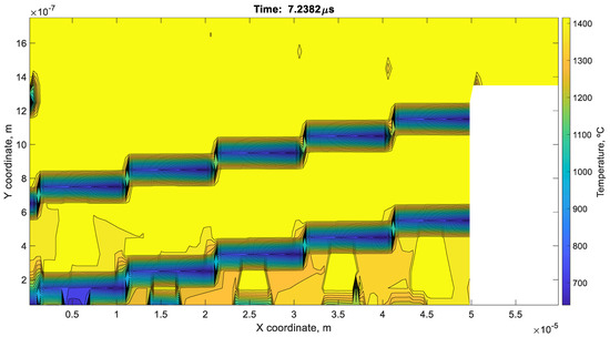
Figure 12.
Temperature distribution at 7.2382 μs.
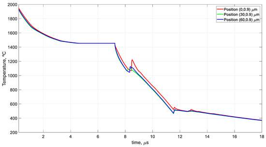
Figure 13.
Temperature evolution in the first cell in the central axis of the y-coordinate of the splat, (0,0.9) μm, in the centre of the splat, (30,0.9) μm, and finally, in the last cell in the central axis of the y-coordinate, (30,1,8) μm.
8. Conclusions
In this work, a network model has been presented for the simulation of the cooling and solidification process of an irregularly shaped splat. Furthermore, the study of the solutions obtained has been carried out using the nondimensionalization technique, which has made it possible to justify the results obtained by simulation, by grouping the variables that influence the process.
In this way, the model allows simulation of the cooling and solidification of the splat of different materials, facilitating the study of the factors that can influence the final shape of the splat. However, due to the meshing used and the phenomena that occur, which are implemented in the mathematical model, the time required to carry out the simulation is long.
This study shows that the process initially forms horizontal bars to maintain the splat structure, and then columns are formed to support them. Finally, the solidification of the gaps between the bars and the columns takes place. This behavior has been explained by grouping the variables into monomials, the main factors affecting it being the relationship between height and length and the relationship between the three phenomena that produce cooling, conduction, convection and radiation. Thus, the formation of the horizontal bars is due to the fact that the conduction phenomenon (Fourier number) predominates over the radiation and convection phenomena (Nusselt number and radiation monomial) on the vertical axis, together with the horizontal radiation and convection which form the aforementioned horizontal bars. This phenomenon is also related to the geometric relation of the problem, because the width is approximately 33 times the height. As mentioned, the columns are then formed where all the phenomena of heat transfer are involved, especially conduction through the substrate. Together, the horizontal bars and the columns maintain the structure of the splat until the solidification process is finished.
Finally, the study carried out using the nondimensionalization technique has been very interesting, because it has allowed us to differentiate two characteristic times, one for cooling and the other for solidification, the second influencing the first. In addition, from its application, dimensionless numbers that are already known as Nusselt, Fourier or Stefan have appeared, or the formation of groupings that relate the square of the geometric dimensions of the problem, among others, highlighting a monomial that relates the phenomenon of radiation and conduction, and is equivalent to the Nusselt number with the phenomenon of convection, and another that relates the solidification time to the Stefan number. Therefore, it will be interesting for future work to further investigate the monomials obtained, as well as the possibility of obtaining universal solutions for the problem.
Author Contributions
Conceptualization, J.F.S.-P. and J.A.M.-N.; methodology, J.F.S.-P., J.A.M.-N., G.J.-C. and A.F.-R.; software, J.F.S.-P. and J.A.M.-N.; validation, J.F.S.-P., J.A.M.-N., G.J.-C. and A.F.-R.; formal analysis, J.F.S.-P.; data curation, J.F.S.-P., J.A.M.-N., G.J.-C. and A.F.-R.; writing—original draft preparation, J.F.S.-P. and J.A.M.-N.; writing—review and editing, J.F.S.-P., J.A.M.-N., G.J.-C. and A.F.-R. All authors have read and agreed to the published version of the manuscript.
Funding
This work was supported by the European Union (FEDER funds) and the Institute for the Business Competitiveness of Castilla y Leon (ICE)—Junta de Castilla y León under project number CCTT3/20/BU/0001.
Data Availability Statement
Data sharing not applicable.
Acknowledgments
The study developed in this article is the result of a collaboration agreement between the Fundación Centro Tecnológico Miranda de Ebro and the Universidad Politécnica de Cartagena (UPCT). The authors appreciate the collaboration of all the institutions and companies mentioned.
Conflicts of Interest
The authors declare no conflict of interest.
References
- Morales, N.G.; Sánchez-Pérez, J.F.; Nicolás, J.A.M.; Killinger, A. Modelling of Alumina Splat Solidification on Preheated Steel Substrate Using the Network Simulation Method. Mathematics 2020, 8, 1568. [Google Scholar] [CrossRef]
- Fauchais, P.; Vardelle, M.; Goutier, S. Atmospheric Plasma Spraying Evolution Since the Sixties through Modeling, Measurements and Sensors. Plasma Chem. Plasma Process. 2017, 37, 601–626. [Google Scholar] [CrossRef]
- Dhiman, R.; McDonald, A.G.; Chandra, S. Predicting splat morphology in a thermal spray process. Surf. Coat. Technol. 2007, 201, 7789–7801. [Google Scholar] [CrossRef]
- Chandra, S.; Fauchais, P. Formation of Solid Splats During Thermal Spray Deposition. J. Therm. Spray Technol. 2009, 18, 148–180. [Google Scholar] [CrossRef]
- Tanaka, Y.; Fukumoto, M. Investigation of dominating factors on flattening behavior of plasma sprayed ceramic particles. Surf. Coatings Technol. 1999, 120–121, 124–130. [Google Scholar] [CrossRef]
- Jiang, X.; Wan, Y.; Herman, H.; Sampath, S. Role of condensates and adsorbates on substrate surface on fragmentation of impinging molten droplets during thermal spray. Thin Solid Films 2001, 385, 132–141. [Google Scholar] [CrossRef]
- McDonald, A.; Moreau, C.; Chandra, S. Thermal contact resistance between plasma-sprayed particles and flat surfaces. Int. J. Heat Mass Transf. 2007, 50, 1737–1749. [Google Scholar] [CrossRef]
- Fukumoto, M.; Huang, Y. Flattening Mechanism in Thermal Sprayed Nickel Particle Impinging on Flat Substrate Surface. J. Therm. Spray Technol. 1999, 8, 427–432. [Google Scholar] [CrossRef]
- Pershin, V.; Lufitha, M.; Chandra, S.; Mostaghimi, J. Effect of Substrate Temperature on Adhesion Strength of Plasma-Sprayed Nickel Coatings. J. Therm. Spray Technol. 2003, 12, 370–376. [Google Scholar] [CrossRef]
- Mantry, S.; Jha, B.; Mandal, A.; Mishra, D.; Mishra, B.; Chakraborty, M. Influence of in-flight particle state diagnostics on properties of plasma sprayed YSZ-CeO2 nanocomposite coatings. Int. J. Smart Nano Mater. 2014, 5, 207–216. [Google Scholar] [CrossRef]
- Zhang, C.; Kanta, A.-F.; Li, C.-X.; Li, C.-J.; Planche, M.-P.; Liao, H.; Coddet, C. Effect of in-flight particle characteristics on the coating properties of atmospheric plasma-sprayed 8mol% Y2O3–ZrO2 electrolyte coating studying by artificial neural networks. Surf. Coat. Technol. 2009, 204, 463–469. [Google Scholar] [CrossRef]
- Zhang, C.; Li, C.J.; Liao, H.; Planche, M.P.; Li, C.X.; Coddet, C. Effect of in-flight particle velocity on the performance of plasma-sprayed YSZ electrolyte coating for solid oxide fuel cells. Surf. Coat. Technol. 2008, 202, 2654–2660. [Google Scholar] [CrossRef]
- Yin, Z.; Tao, S.; Zhou, X.; Ding, C. Particle in-flight behavior and its influence on the microstructure and mechanical properties of plasma-sprayed Al2O3 coatings. J. Eur. Ceram. Soc. 2008, 28, 1143–1148. [Google Scholar] [CrossRef]
- Syed, A.; Denoirjean, A.; Hannoyer, B.; Fauchais, P.; Denoirjean, P.; Khan, A.; Labbe, J. Influence of substrate surface conditions on the plasma sprayed ceramic and metallic particles flattening. Surf. Coat. Technol. 2005, 200, 2317–2331. [Google Scholar] [CrossRef]
- Okumus, S.C. Microstructural and mechanical characterization of plasma sprayed Al2O3–TiO2 composite ceramic coating on Mo/cast iron substrates. Mater. Lett. 2005, 59, 3214–3220. [Google Scholar] [CrossRef]
- Zhang, H.; Wang, X.; Zheng, L.; Jiang, X. Studies of splat morphology and rapid solidification during thermal spraying. Int. J. Heat Mass Transf. 2001, 44, 4579–4592. [Google Scholar] [CrossRef]
- Pasandideh-Fard, M.; Pershin, V.; Chandra, S.; Mostaghimi, J. Splat Shapes in a Thermal Spray Coating Process: Simulations and Experiments. J. Therm. Spray Technol. 2002, 11, 206–217. [Google Scholar] [CrossRef]
- Robert, C.; Denoirjean, A.; Vardelle, A.; Wang, G.-X.; Sampath, S. Nucleation and Phase Selection in Plasma-Sprayed Alumina: Modeling and Experiment. In Proceedings of the International Thermal Spray Conference, Nice, France, 25–29 May 1998; pp. 407–412. [Google Scholar] [CrossRef]
- Pasandideh-Fard, M.; Bhola, R.; Chandra, S.; Mostaghimi, J. Deposition of tin droplets on a steel plate: Simulations and experiments. Int. J. Heat Mass Transf. 1998, 41, 2929–2945. [Google Scholar] [CrossRef]
- Fauchais, P.; Vardelle, M.; Vardelle, A.; Bianchi, L.; Léger, A.C. Parameters controlling the generation and properties of plasma sprayed zirconia coatings. Plasma Chem. Plasma Process. 1995, 16, S99–S125. [Google Scholar] [CrossRef]
- Levi, C.G.; Jayaram, V.; Valencia, J.J.; Mehrabian, R. Phase selection in electrohydrodynamic atomization of alumina. J. Mater. Res. 1988, 3, 969–983. [Google Scholar] [CrossRef]
- Wang, S.P.; Wang, G.X.; Matthys, E.F. Melting and resolidification of a substrate in contact with a molten metal: Operational maps. Int. J. Heat Mass Transf. 1998, 41, 1177–1188. [Google Scholar] [CrossRef]
- Vardelle, M.; Vardelle, A.; Fauchais, P.; Moreau, C. Pyrometer system for monitoring the particle impact on a substrate during a plasma spray process. Meas. Sci. Technol. 1994, 5, 205–212. [Google Scholar] [CrossRef]
- Allen, R.F. The role of surface tension in splashing. J. Colloid Interface Sci. 1975, 51, 350–351. [Google Scholar] [CrossRef]
- Fukumoto, M.; Suzuki, D.; Maeda, N.; Jinbo, M. The splat formation issue in thermal spray processes. WIT Trans. Eng. Sci. 2017, 116, 181–185. [Google Scholar] [CrossRef]
- Yang, E.J.; Luo, X.T.; Yang, G.J.; Li, C.X.; Li, C.J.; Takahashi, M. Epitaxial grain growth during 8YSZ splat formation on polycrystalline YSZ substrates by plasma spraying. Surf. Coat. Technol. 2015, 274, 37–43. [Google Scholar] [CrossRef]
- Pech, J.; Hannoyer, B.; Denoirjean, A.; Fauchais, P. Influence of Substrate Preheating Monitoring on Alumina Splat Formation in DC Plasma Process. In Proceedings of the International Thermal Spray Conference, Montreal, QC, Canada, 8–11 May 2000; pp. 759–765. [Google Scholar] [CrossRef]
- Espie, G.; Fauchais, P.; Hannoyer, B.; Labbe, J.C.; Vardelle, A. Effect of metal particles oxidation during the APS on the wettability. Ann. N. Y. Acad. Sci. 1999, 891, 143–151. [Google Scholar] [CrossRef]
- Pech, J.; Hannoyer, B.; Lagnoux, O.; Denoirjean, A.; Fauchais, P. Influence of preheating parameters on the plasma-jet oxidation of a low-carbon steel. High Temp. Mater. Process. 2011, 15, 51–60. [Google Scholar] [CrossRef]
- Valette, S.; Denoirjean, A.; Lefort, P.; Fauchais, P. Influence of dc plasma preheating on oxide layers formed by furnace heating on low carbon steel substrates and resulting adhesion/cohesion of alumina coatings. High Temp. Mater. Process. 2003, 7, 11–215. [Google Scholar] [CrossRef]
- Maitre, A.; Denoirjean, A.; Fauchais, P.; Lefort, P. Plasma-jet coating of preoxidized XC38 steel: Influence of the nature of the oxide layer. Phys. Chem. Chem. Phys. 2002, 4, 3887–3893. [Google Scholar] [CrossRef]
- Sobolev, V.V.; Guilemany, J.M. Flattening of Droplets and Formation of Splats in Thermal Spraying: A Review of Recent Work—Part 2. J. Therm. Spray Technol. 1999, 8, 301–314. [Google Scholar] [CrossRef]
- Sobolev, V.V.; Guilemany, J.M. Flattening of Droplets and Formation of Splats in Thermal Spraying: A Review of Recent Work—Part 1. J. Therm. Spray Technol. 1999, 8, 87–101. [Google Scholar] [CrossRef]
- Vogt, H.; Atkinson, G.; Nenzi, P.; Warning, D.; Ngspice Contributors Team. NgSpice. 2023. Available online: https://ngspice.sourceforge.io/docs/ngspice-html-manual/manual.xhtml (accessed on 26 May 2023).
- Jin, T.; Li, F.; Peng, H.; Li, B.; Jiang, D. Uncertain barrier swaption pricing problem based on the fractional differential equation in Caputo sense. Soft Comput. 2023, 27, 11587–11602. [Google Scholar] [CrossRef]
- Dutt, N.; Hedau, A.J.; Kumar, A.; Awasthi, M.K.; Singh, V.P.; Dwivedi, G. Thermo-hydraulic performance of solar air heater having discrete D-shaped ribs as artificial roughness. Environ. Sci. Pollut. Res. 2023, 1–22. [Google Scholar] [CrossRef] [PubMed]
- Du, X.; Liu, X.; Song, Y. Analysis of the Steady-Stream Active Flow Control for the Blended-Winged-Body Underwater Glider. J. Mar. Sci. Eng. 2023, 11, 1344. [Google Scholar] [CrossRef]
- Vitanov, N.K.; Dimitrova, Z.I. Computation of the Exact Forms of Waves for a Set of Differential Equations Associated with the SEIR Model of Epidemics. Computation 2023, 11, 129. [Google Scholar] [CrossRef]
- Cao, J.; Zhao, D.; Tian, C.; Jin, T.; Song, F. Adopting improved Adam optimizer to train dendritic neuron model for water quality prediction. Math. Biosci. Eng. 2023, 20, 9489–9510. [Google Scholar] [CrossRef]
- Yadav, H.; Roy, A.K.; Kumar, A. The influence of interactions between two high-rise buildings on the wind-induced moment. Asian J. Civ. Eng. 2023, 1–13. [Google Scholar] [CrossRef]
- Sánchez-Pérez, J.F.; Marin, F.; Morales, J.L.; Cánovas, M.; Alhama, F. Modeling and simulation of different and representative engineering problems using Network Simulation Method. PLoS ONE 2018, 13, e0193828. [Google Scholar] [CrossRef]
- García-Ros, G.; Alhama, I.; Cánovas, M. Use of discriminated nondimensionalization in the search of universal solutions for 2-D rectangular and cylindrical consolidation problems. Open Geosci. 2018, 10, 209–221. [Google Scholar] [CrossRef]
- Sánchez-Pérez, J.; Alhama, I. Universal curves for the solution of chlorides penetration in reinforced concrete, water-saturated structures with bound chloride. Commun. Nonlinear Sci. Numer. Simul. 2020, 84, 105201. [Google Scholar] [CrossRef]
- Sánchez-Pérez, J.F.; García-Ros, G.; Conesa, M.; Castro, E.; Cánovas, M. Methodology to Obtain Universal Solutions for Systems of Coupled Ordinary Differential Equations: Examples of a Continuous Flow Chemical Reactor and a Coupled Oscillator. Mathematics 2023, 11, 2303. [Google Scholar] [CrossRef]
- González, N.; Zapata, J.; Martínez, V.; Gadow, R.; García, J. Manufacturing parameter analysis for alumina coating on steel substrate by automated image processing of isolated splats samples. PLoS ONE 2020, 15, e0240928. [Google Scholar] [CrossRef]
- Bejan, A.; Kraus, A.D. Heat Transfer Handbook; John Wiley & Sons, Inc.: Hoboken, NJ, USA, 2003. [Google Scholar]
- Sánchez-Pérez, J.F.; Mascaraque-Ramírez, C.; Nicolás, J.A.M.; Castro, E.; Cánovas, M. Study of the application of PCM to thermal insulation of UUV hulls using Network Simulation Method. Alex. Eng. J. 2021, 60, 4627–4637. [Google Scholar] [CrossRef]
- Fernández, C.F.G.; Alhama, F.; Sánchez, J.F.L.; Horno, J. Application of the network method to heat conduction processes with polynomial and potential-exponentially varying thermal properties. Numer. Heat Transf. Part A Appl. 1998, 33, 549–559. [Google Scholar] [CrossRef]
- Perez, J.F.S.; Conesa, M.; Alhama, I. Solving ordinary differential equations by electrical analogy: A multidisciplinary teaching tool. Eur. J. Phys. 2016, 37, 065703. [Google Scholar] [CrossRef]
- Zueco, J.; Alhama, F.; Fernández, C.F.G. Inverse determination of heat generation sources in two-dimensional homogeneous solids: Application to orthotropic medium. Int. Commun. Heat Mass Transf. 2006, 33, 49–55. [Google Scholar] [CrossRef]
- Fernández, M.; Sánchez-Pérez, J.F.; del Cerro, F.; Conesa, M. Mathematical Model to Calculate Heat Transfer in Cylindrical Vessels with Temperature-Dependent Materials. Axioms 2023, 12, 335. [Google Scholar] [CrossRef]
- Kreith, F.; Manglik, R.M.; Bohn, M.S. Principles of Heat Transfer, SI Edition, 7th ed.; Global Engineering: Tokyo, Japan, 1999; Volume 2. [Google Scholar]
- Vuik, C. Some Historical Notes about the Stefan Problem. Unknown. 1993. Available online: https://www.researchgate.net/publication/2764813_Some_historical_notes_about_the_Stefan_problem (accessed on 29 May 2023).
- Lock, G.S.H. On the Use of Asymptotic Solutions to Plane Ice—Water Problems. J. Glaciol. 1969, 8, 285–300. [Google Scholar] [CrossRef]
- Valencia, J.J.; Quested, P.N. Thermophysical Properties, ASM Handbook; ASM: Almelle, The Netherlands, 2008; Volume 15. [Google Scholar]
Disclaimer/Publisher’s Note: The statements, opinions and data contained in all publications are solely those of the individual author(s) and contributor(s) and not of MDPI and/or the editor(s). MDPI and/or the editor(s) disclaim responsibility for any injury to people or property resulting from any ideas, methods, instructions or products referred to in the content. |
© 2023 by the authors. Licensee MDPI, Basel, Switzerland. This article is an open access article distributed under the terms and conditions of the Creative Commons Attribution (CC BY) license (https://creativecommons.org/licenses/by/4.0/).

