Abstract
Intelligent diagnosis of faults in an aero-hydraulic pipeline is important for condition monitoring of its systems. However, there are no more qualitative formulas or feature indicators to describe the faults of aero-hydraulic pipelines because of the complexity and diversity of aero-hydraulic pipeline systems, which leads to a very complex pipeline fault mechanism. In addition, although it is well known that the expression of interpretable and representable pipeline intelligent diagnosis models with pipeline fault characteristics are buried in high background noise and strong noise disturbance conditions in practical industrial scenarios, this has yet to be discussed. Inspired by the demand, this paper proposes a novel diagnosis strategy: the 1D-convolutional space-time fusion strategy for aero-engine hydraulic pipelines. Firstly, by optimizing the convolutional neural network and using it to design a one-dimensional convolutional neural network (1DCNN) with a wide input scale to expand the input field of perception, thereby obtaining more comprehensive spatial information of the pipeline data, which can effectively extract richer short sequence features. Secondly, a network of bidirectional gated recurrent Unit (Bi-GRU) is proposed, which integrates a short sequence of high-dimensional features for temporal information fusion, resulting in a certain degree of avoiding memory loss and gradient dispersion caused by the too-large step size. It is demonstrated that, for the noise signal and variable pressure signal, the fault identification accuracy approximated 95.9%, proving the proposed strategy’s robustness. By comparing with the other five methods, the proposed strategy has the ability to identify 10 different fault states in the aero-hydraulic pipeline with higher accuracy.
Keywords:
fault diagnosis; aero-hydraulic pipeline; 1D-convolutional neural network; bidirectional gated recurrent unit; spatial-time fusion MSC:
68T07
1. Introduction
The aero-engine hydraulic pipeline system plays an extremely crucial role in aero-engines. Meanwhile, as a complex power support system, it often works in extreme environments such as high pressure, high rotating speeds, high temperature, high strength and variable load. In this case, the failure of the aero-engine pipeline system will have a critical impact on its safety and reliability [1,2,3]. In engineering, several kinds of failures often occur in aero-engine hydraulic pipeline systems, which primarily exhibit vibration failures. According to statistics from relevant departments, 36.7% of the engine failures of civil aircraft are due to hydraulic piping system failures, and 30% of the engine failures of military aircraft are also due to the same reason [4]. Therefore, it is of great theoretical significance and engineering value to carry out research on the vibration failure mechanism of aero-engine hydraulic pipelines and accurately identify typical faults such as cracks, wear and pits of hydraulic pipelines, which will guarantee the safe and efficient service of aero-engines. The typical failure diagram of the aero-hydraulic pipeline body is shown in Figure 1. In recent years, to avoid the vibration failure of the aero-engine pipeline system, a few research studies have been conducted on the mechanical parameters and the pipeline model of the aero-engine. For example, Zhezhu Li et al. [5] proposed a crack fault diagnosis method for aero-hydraulic pipelines based on HHT. Hu Ding et al. [6,7,8] established a nonlinear coupled dynamics model for the hydraulic pipeline based on the Timoshenko beam. Yijiang Ma et al. [9,10] proposed a method for analyzing the natural frequency of a slant crack cantilever beam considering respiration. Bergant Anton et al. [11] used the finite element method to simulate and analyze the pipeline, discovering the fluid–structure coupling vibration characteristics of the pipeline, and applied it to the study of pipeline vibration faults. Hongzhen Zhu et al. [12] respectively analyzed the dynamic characteristics of hydraulic pipelines by using the dynamic stiffness method and spectral element method. Mingyao Liu et al. [13,14] studied the vibration response of pipelines under complex boundary conditions and bending loads. Jiantao Li et al. [15] analyzed the transient response of the flow pipeline under periodic excitation and proposed a vibration suppression method.

Figure 1.
Typical failure diagram of aero-engine hydraulic pipeline body [2,3].
Deep learning theory, which imitates the learning style of the human brain, constructs multiple nonlinear mapping-level network models to extract the features of the input vibration signals layer-by-layer, and then obtains the implied features in the data. This is an intelligent model that combines feature extraction and pattern recognition into one. The convolutional neural network proposed by G. E. Hinton et al. [16], as a new approach in the field of deep learning, has a unique network structure, powerful learning ability and high generalization capability. Therefore, this approach is widely used in the fields of image recognition, speech recognition and fault diagnosis [17,18,19,20,21,22,23,24].
During recent years, the convolutional neural network has been successfully applied in the field of fault diagnosis [25], especially in the pattern recognition of rotating machinery faults [26,27,28,29,30]; for example, Haidong Shao et al. [31] proposed a bearing fault feature learning method based on compressed sensing and an improved convolutional deep confidence network. Feng Jia et al. [32] proposed a convolutional neural network based on different weight loss functions to realize fault classification of unbalanced bearing samples. Han-Yun Chen et al. [33] discusses the convolutional neural network for vibration signal analysis, including applications in machining surface roughness estimation, bearing faults diagnosis and tool wear detection. Davor Kolar et al. [34] utilized an optimized convolutional artificial neural network to classify the raw triaxial accelerometer signal input. Shiue-Der Lu et al. [35] combined a CNN with the chaos theory and the EMD method for the attenuation fault recognition of power capacitors. Habbouche, et al. [36] proposed an approach for bearing fault early diagnosis based on the variational mode decomposition, for detection and diagnosis purposes. The achieved results show that the proposed approach is clearly promising for bearing degradation monitoring. Huichao Zhang, et al. [37] proposed a bearing fault diagnosis method based on adaptive multivariate variational mode decomposition (AMVMD) and multi-scale convolutional neural network (Multi-scale CNN). The results show that the fault diagnosis accuracy of AMVMDMSCNNs can achieve 98.60%.
In these works, the vibration-date’s temporal properties were usually omitted and led to less optimal results concerning both performance and the efficiency of solutions. The gated recurrent unit is an optimization of the long short-term memory [38], which has a simple model structure and strong convergence in order to effectively cope with the problem of gradient disappearance in the recurrent neural network. Compared with long short-term memory networks, a gated recurrent unit has the advantage of a 1/3 reduction in the number of parameters and the ability to reduce over-fitting. For example, a mechanical fault diagnosis algorithm based on the recurrent neural network was proposed by Li-peng Zhang et al. [39]. Qin, C., et al. [40]. proposed an enhanced transformer-based detection model for detecting the cutterhead clogging status of shield tunneling machines. The results show that the proposed model achieves accurate detection of shield machine cutterhead clogging status [41]. A diesel engine acoustic fault diagnosis method based on variational modal decomposition mapping Mel frequency cepstral coefficients (MFCC) and long-short-term memory network is proposed. To sum up the above, deep learning methods have witnessed many breakthroughs in the field of mechanical fault diagnosis; however, there is still a lot of potential to improve the intelligent diagnosis model for aero-engine hydraulic pipeline systems.
Due to the complexity and diversity of the structure of the aero-hydraulic pipeline, as well as the influence of fluid–structure coupling vibration characteristics and loud external noises, the fault mechanism of the hydraulic pipeline is relatively complex. Moreover, the fault vibration signals are significantly nonlinear and nonstationary, which makes it difficult to accurately capture the fault characteristics of the hydraulic pipeline. This paper proposes a novel 1D-convolutional spatial-time fusion strategy for data-driven fault diagnosis of the aero-engine pipeline. The major novelties and contributions are listed as follows.
- (1)
- In this paper, the three stages of vibration signal preprocessing, feature extraction and fault identification of an aero-engine hydraulic pipeline are unified into one model, and the end-to-end fault diagnosis mode of pipeline fault is truly realized. Furthermore, this method effectively avoids the problem of partial pipeline fault information loss caused by signal transformation processing.
- (2)
- To meet the challenge of powerful noise interference of aero-hydraulic engines, this paper introduces the designed spatial feature fusion module into the temporal feature fusion module to develop a new space-time fusion model. As a result, the model can fully integrate the spatial and temporal characteristics of aero-hydraulic pipeline vibration data, which is the first attempt in the hydraulic pipeline field. Thus, the nonlinear fitting capability of the proposed model is further improved.
- (3)
- The measured aero-engine hydraulic pipeline fault data were input into a 1D-convolutional spatial-time fusion strategy for training, and it was demonstrated that the proposed strategy could diagnose faults with 99.7% accuracy. It is noteworthy that the fault identification accuracy is close to 95.9% for noisy and variable pressure signals. And by comparing with the other five cutting-edge methods, the proposed strategy has the ability to identify 10 different fault states in the aero-engine hydraulic pipeline with higher accuracy. Consequently, it can meet the requirements of diagnostic accuracy and robustness for complex systems of aero-hydraulic pipelines.
The remaining parts of this paper are organized as follows. Section 1 demonstrates the basic theory of this paper and the framework of the proposed strategy. Section 2 presents the data collection from the test bed built independently in this paper, and the model building and debugging. Section 3 visualizes and analyzes the classification results. Section 4 presents the result and comparison analyses with several other models. Section 5 serves as the conclusion and the future outlook.
2. Fundamental Theory
In this part, firstly, the principles of convolutional neural networks and gated recurrent units are introduced. Secondly, mainly based on deep learning theory, a novel 1D-convolutional spatial-time fusion model. Finally, the parameters of the proposed model are explained.
2.1. Spatial Fusion
With the advantage of convolutional operation, the convolutional neural network [42] can express the original data at a higher level and in a more abstract way, which is mainly composed of five parts: the input layer, the convolutional layer, the pooling layer, the full connection layer and the output layer.
2.1.1. Convolution Layer
The convolution layer mainly carries out feature extraction through the convolution check feature maps [43,44]. The mathematical expression of the convolution process is:
In the equation, is the j-th convolution region of the feature map of l − 1 layer, is an element of it; is the weight matrix of the corresponding convolution kernel; is the offset term.
2.1.2. Activation Function
Activation functions are like the brain in a human neural network and play a central role in the training of deep neural networks. The rectified linear unit (ReLU), = ) is a commonly chosen activation function in deep learning because of its simplicity, but ReLU has a disadvantage: the dying ReLU problem. To overcome the shortcomings of ReLU, the activation function chosen in this paper is Leaky ReLU, whose mathematical equation is:
2.1.3. Pooling Layer
The pooling layer reduces the dimensionality of the feature map to reduce the computational complexity, while retaining the strong features and removing the weak ones, and making them scale invariant to prevent overfitting. Among them, the maximum pooling method is the most effective and widely used, and its mathematical expression is shown in Equation (3)
where represents the t-th neuron of the i-th feature map in layer 1. w represents the width of the convolution kernel and j represents the j-th pooling kernel.
2.2. Temporal Fusion
The gated recurrent unit (GRU) [45] is a very important popular variant of RNN, which solves the long dependency problem in RNN networks in the most cost-effective way [46], and it can complement the drawbacks of long training time, more parameters and complicated internal computation of LSTM. The GRU cell undergoes constant update processing internally, and the cell update process is shown in Equations (4)–(8). The structures of the gated recurrent unit cell and bidirectional gated recurrent unit is shown in Figure 2.
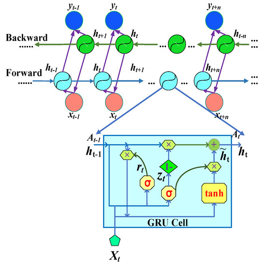
Figure 2.
The structures of GRU cell and Bi-GRU.
In Figure 2, zt represents the update gate and rt represents the reset gate. The update gate and the reset gate are responsible for controlling the input information, and the input is the information of the previous state, in which the updaters control the numerical degree of the previous state entering the current state; instead, resetting the door controls the amount of value omitted from the previous state to the current state. Its parts satisfy the relationship as follows:
Update the value of the gate at time t:
where Wz represents the weight of the update gate, [ ] represents the connection of two vectors, ht−1 represents the hidden state at time t − 1, and xt represents the input at time t.
Reset the value of the door at time t:
where, represents the weight of the reset gate.
The value of the candidate set at time t:
where, A weight that represents a hidden state.
The hidden state of the t-moment network:
Output of the t-moment network:
where, represents the weight of the hidden layer to the output layer.
Based on GRU, Bi-GRU is formed by modeling the data in a bidirectional way, in which the forward GRU models the data from front to back; in turn, the data are modeled from the back to the front to the GRU, and the output of each step is formed after the two types of GRU are merged, and compared with the general GRU; Bi-GRU can obtain data information more accurately and efficiently.
2.3. Proposed Strategy
Due to the complexity and diversity of the structure of the aero-hydraulic pipeline, as well as the influence of fluid–structure coupling vibration characteristics and loud external noises, the fault mechanism of the hydraulic pipeline is relatively complex. Firstly, this paper proposes a novel 1D-convolutional spatial-time fusion strategy for data-driven fault diagnosis of the aero-engine pipeline. Secondly, the 1D-convolutional spatial-time fusion strategy is verified to be robust to intense noise signals by adding Gaussian noise to the hydraulic pipeline vibration data. Finally, in this paper, the three stages of vibration signal preprocessing, feature extraction and fault identification of an aero-engine hydraulic pipeline are unified into one model, and the end-to-end fault diagnosis mode of pipeline fault is truly realized. Furthermore, this method effectively avoids the problem of partial pipeline fault information loss caused by signal transformation processing. It provides a novel idea for the intelligent diagnosis of early faults of the aero-hydraulic pipeline. The overall framework of the proposed 1D-convolutional spatial-time fusion strategy is shown in Figure 3.
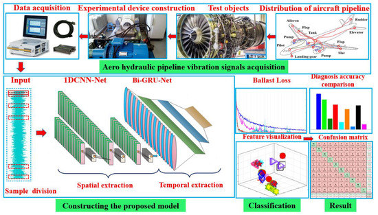
Figure 3.
Overall frame of the proposed 1D-convolutional spatial-time fusion strategy.
- (1)
- Signal acquisition and division: different types of aero-pipeline vibration data are acquired simultaneously using sensors and divided with windows of equal length to obtain sample signals.
- (2)
- Data set creation: the sample signals are stacked into a sample in a certain order. The data set is created after the above operation and divided into training and testing sets.
- (3)
- Model design and training: The spatial-time fusion strategy is designed according to Section 1. After that, the optimized 1D-CNN model is used to perform spatial information fusion on the aero-hydraulic pipeline vibration signal to enhance the extraction capability of local features. At the same time, the advantages of the Bi-GRU model on the global features of the vibration signal are exploited for temporal information fusion, and the 1D-convolutional spatial-time fusion strategy with better performance is obtained by debugging each parameter through many experiments.
- (4)
- Robustness verification: Gaussian noise was added to the aero-hydraulic pipeline testing set to verify the robustness of the model against strong noise signals.
- (5)
- Intelligent diagnosis: this paper proposes a novel 1D-convolutional spatial-time fusion strategy for data-driven fault diagnosis of the aero-engine pipeline, and it can consider the local characteristics and global characteristics of hydraulic pipelines, and realize the fusion of coarse and fine granular features, so as to comprehensively depict the fault data of aviation hydraulic pipelines, so that the proposed model can realize intelligent classification of aviation hydraulic pipeline faults. For the same data set, the 1D-convolutional spatial-time fusion strategy and other 5 models, including conventional one-dimensional convolutional neural network(1D-CNN), bi-directional gated recurrent unit (Bi-GRU), long short-term memory (LSTM), back propagation neural network (BPNN) and support vector machine (SVM), are trained separately to investigate the effectiveness and feasibility of the proposed method for the diagnosis of aero-hydraulic pipeline fault signals after comparison and analysis.
2.4. Strategy Architecture
In addition, deep learning methods have witnessed many breakthroughs in the field of mechanical fault diagnosis; however, there is still a lot of potential to improve the intelligent diagnosis model for aero-hydraulic pipelines. At the same time, a representative CNN model [47,48] (LeNet-5) is optimally designed in this paper to better process a 1D-CNN model hydraulic pipeline vibration signal as an input quantity. The design in this paper consists of 3 convolutional layers and 3 sampling layers alternately. Leaky ReLU is a variant of ReLU, which can not only can solve the gradient vanishing and explosion problems in traditional neural network training steps, but also speeds up the convergence rate of network models, and simplifies computational costs and avoids over-fitting problems, as well as mitigating the neuronal death caused by ReLU [49,50]. Thus, this paper chooses the Leaky ReLU function as the activation function of the 1D-convolutional spatial-time fusion strategy. The pooling layer uses Max Pooling, which obtains eigenvalues independent of the position of the input matrix, enhancing robustness to shifts. Thus, it is a critical step in the classification of features of the time-domain signal.
Moreover, the utilization of single-directional gated recurrent units in fault diagnosis and classification means that the transmission of data states is simply propagated from front to back in one direction; thus, it can only capture the previous information, which makes the important information easily lost and the vectors that best reflect the characteristics of the hydraulic pipeline data may not be fully fused [51,52]. To link the current moment’s output with the state information before and after the hydraulic pipeline data, this paper utilizes a bi-directional gated recurrent unit, which can make up for the defects of the single-directional gated recurrent unit model. Meanwhile, the bidirectional gated recurrent unit model provides the advantages of global characteristics of vibration signals for temporal information fusion. The classifier chosen for the fully connected layer in this paper is SoftMax regression, obtained by extending the logistic regression model and is well-suited for identifying multi-classified targets [53]. Finally, the weights and biases are updated using the Adam algorithm according to the output results. Furthermore, to meet the challenge of powerful noise interference of aero-hydraulic engines, this paper introduces the designed spatial feature fusion module into the temporal feature fusion module to develop a new space-time fusion strategy, illustrated in Figure 4. The coarse and fine-grained features are fused to comprehensively characterize the aero-hydraulic pipeline data with local correlation, and it can effectively avoid the characteristic extraction method of manual intervention, causing the difficulty of insensitive pipeline fault characterization.
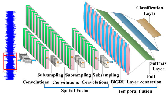
Figure 4.
Structure illustration of the proposed 1D-convolutional spatial-time fusion strategy.
In addition, the utilization of single-directional gated recurrent units in fault diagnosis and classification means that the transmission of data states is simply propagated from front to back in one direction; thus, it can only capture the previous information, which makes the important information easily lost and the vectors that best reflect the characteristics of hydraulic pipeline data may not be fully fused.
3. Experiment
In this part, firstly, the experimental bench of the aero-hydraulic pipeline system was built. Secondly, according to the experimental protocol, the sensor was used to collect the aero-pipeline fault signal and conduct a preliminary analysis. Finally, an appropriate amount of samples were selected and input to the built model for training, to obtain the best parameters of the model.
3.1. Data Source
The hydraulic pipeline material chosen for the experiment is stainless steel. The aero-engine hydraulic pipeline power system test device is shown in Figure 5, which consists of electromotor, plunger pump, exciter, pipeline system and control system, etc.
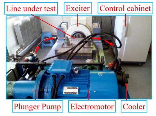
Figure 5.
Hydraulic power system measurement equipment.
In both straight and bent pipe structures, an acceleration sensor was placed at each end of the pipe and in the middle to collect vibration data synchronously, and the vibration signals were measured separately. Thirty types of sample data were obtained, as shown in Figure 6 and Figure 7. The measurement positions were arranged from left to right as 1, 2 and 3, and the measurement parameters were set as in Table 1.
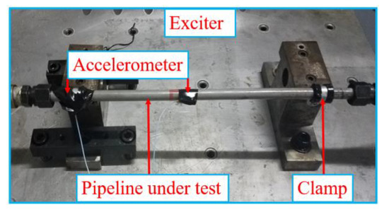
Figure 6.
Measurement diagram of pipeline fault of aero-hydraulic straight pipeline system.
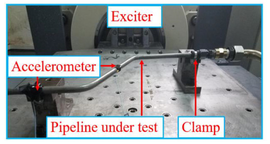
Figure 7.
Measurement diagram of pipeline fault of aero-hydraulic bending pipeline system.

Table 1.
Measurement parameter setting table.
3.2. Data Declaration
Air-frame noise and engine noise are the main noise sources of aircraft, with engine noise accounting for the largest proportion of aircraft noise [54]. The aero-hydraulic pipeline system is affected by the complex engine structure and harsh working environment, which leads to the powerful engine noise becoming the main disturbing factor when extracting aero-hydraulic pipeline fault characteristic information. On the one hand, the engine pipeline system has a large number of parts, limited space and a variety of complex structures. On the other hand, the pipeline system needs to be fixed on the air-frame with the complex shape of the aircraft wall plate and is subject to different levels of noise interference from different areas of the engine, such as engine jet noise, fan noise, combustion chamber noise and turbine noise. This leads to a strong uncertainty of the noise and the randomness of the noise level when it is variable [55].
In this case study, the actual measured fault data of the aero-engine hydraulic pipelines were obtained in the laboratory, which is less noisy than the application environment. So directly using it ignores the problem of noise interference generated by the actual operation of the aero-engine. To simulate the noise disturbance of the pipeline in the real-time complex environment more realistically, Gaussian white noise with SNR = 20 dB and SNR = 10 dB was added to the measured time-domain signal, respectively, which can be defined as:
where and are the amplitude of the signal and noise, respectively.
After that, the test set with mixed-noise signal was input to trained by the 1D-convolutional spatial-time fusion strategy, thus testing the robustness and accuracy of the proposed model. Specifically, the addition of white noise can simulate the signals present in complex environments, so the classification model must be resistant to noise. In addition, by experimenting with the addition of white noise of different intensities, it is also possible to evaluate the responsiveness and robustness of the model to different intensities of noise. This is an important guideline for selecting the appropriate noise suppression method and setting parameters in practical applications. The time-domain wave-forms of aero-hydraulic bend pipeline health vibration signal, pipeline end crack and middle crack fault, pipeline end crater and middle crater fault under five cases collected from measurement point 1 after noise dyeing are shown in Figure 8a–d.
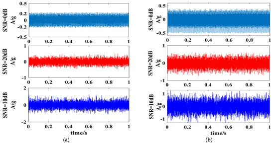
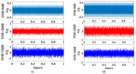
Figure 8.
(a) Time-domain waveform diagram of pipeline health status; (b) Time-domain waveform diagram of cracked middle of pipeline fault; (c) Time-domain waveform diagram of cracked pipeline end fault; (d) Time-domain waveform diagram of pipeline middle pit fault.
Figure 8 shows that the amplitude of the vibration signal of the aero-hydraulic pipeline before the dyeing noise is generally very small, and its time-domain waveform is quite regular. Figure 8a shows that when the hydraulic pipeline is healthy, the amplitude of its vibration signal is the smallest, and the magnitude is around 0.2 g.
From Figure 8b–d, it can be found that when cracks or pits appear in different locations of the aero-hydraulic pipeline, the amplitude of the vibration signal will increase significantly, and the magnitude is above 0.4 g, which is 2–3 times of the amplitude of the healthy state of the aero-hydraulic pipeline.
After adding noise, the change amplitude of the vibration signal of hydraulic pipeline increases, and the amplitude increases to about 1 time of the previous one. At the same time, the time-domain waveform changes significantly.
3.3. Model Parameter
The aero-hydraulic pipeline is excited by the pump source superimposed on the simple harmonic excitation of the dual-rotor base, resulting in its vibration response showing the characteristics of broadband multi-harmonic frequency. Moreover, the fault signal is accompanied by substantial noise interference. It is challenging to improve further the generalization performance of the hydraulic pipeline fault diagnosis strategy and find the hyperparameters suitable for the proposed strategy. Therefore, this thesis mainly analyzes the influence of two essential hyperparameters, learning rate and batch size, on the robustness of the proposed strategy.
Designing the learning rate size: the learning rate controls the degree of change of the network weights to meet the gradient loss, which significantly impacts the iteration rate and obtaining the optimal solution [56]. In this paper, the initial learning rate was set to 0.01, 0.001 and 0.0001, using the control variables method to ensure the other variables were the same. Then, the hydraulic pipeline faults data were input to the proposed strategy iteration for 20 rounds. Under different learning rates, the loss values during model training were obtained, as shown in Figure 9.
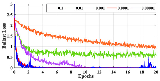
Figure 9.
Loss values at different learning rates.
Figure 9 shows that the learning rate decreases as training sessions increase. The test set works optimally at a learning rate of 0.0001, which means that the loss value of the model is very close to the minimum after 3 iterations. The model training curve converges quickly, and the loss value gradually stabilizes at zero for a learning rate of 0.0001. However, overfitting occurs at learning rates of 0.1, 0.01, 0.001 and 0.00001, indicating that the model’s classification performance is poor in these cases.
Choosing a batch size: the batch size requires an appropriate value in response to the demand of the actual model. Therefore, models with batch sizes 16, 32, 64 and 128 were designed based on the aero-hydraulic pipeline fault data set. Figure 10 shows that, when the batch value is 32, the model training curve rapidly converges and the loss value is zero, which is relatively the best result. However, when the batch value is set to 16, 64 and 128, the overfitting phenomenon occurs lightly or heavily, and the results are not very satisfactory.
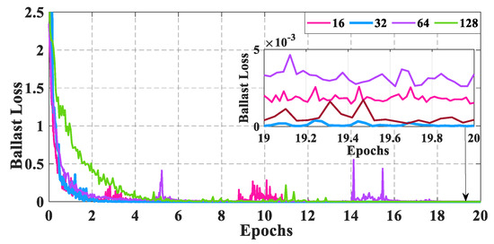
Figure 10.
Loss values at different batch sizes.
An appropriate amount of aero-hydraulic pipeline vibration data are used, and according to the basic principle of parameter setting, repeated debugging is carried out, and the specific parameters of the network model are finally obtained, as shown in Table 2. The size of convolutional kernels in each of these layers is 3 × 1.

Table 2.
Parameter Amount for 1D-convolutional spatial-time fusion strategy.
3.4. Training Setting
In deep learning, the loss value measures the difference between the output predicted by the model and the actual label. In general, the loss function is an important part of deep learning models, which defines the gap between the model output and the actual label. The role of the loss value mainly includes three aspects: first, by minimizing the loss value to adjust the model parameters, so that the model can better fit the training data and improve the diagnostic accuracy. Second, the loss value training curve can be used as one of the indicators to evaluate the performance of the model, and the optimal model is selected by comparing the loss values of different models on the same data set. Third, by controlling the size of the loss value, the model can be avoided from overfitting on the training data and the generalization ability of the model can be improved. Therefore, to demonstrate the stability of the 1D-convolutional spatial-time fusion strategy designed in this paper, the data set is trained by random sampling. Based on the same data set, 1D-convolutional spatial-time fusion was utilized to compare and analyze the hydraulic pipeline fault diagnosis with five fault diagnosis models, including conventional CNN, Bi-GRU, LSTM, BPNN and SVM. The correlation between the loss rate of the data set and the number of iterations is presented in Figure 11.
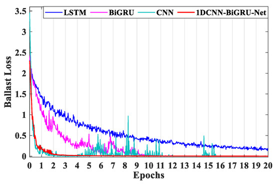
Figure 11.
Comparison curve of loss values the proposed method and other methods.
Figure 11 shows that the loss value of the training samples, based on the proposed 1D-convolutional spatial-time fusion strategy, decreases with the increase in the number of iterations and converges to zero after 2 iterations. Moreover, the model reaches the convergence condition. Meanwhile, the model remains very stable after 20 iterations, indicating the ideal training effect. This improves the convergence speed of the 1D-convolutional spatial-time fusion strategy, thus reducing the training time, and, thus, can be applied to the pattern recognition of aero-hydraulic pipeline fault diagnosis. Due to intense noise interference, the loss value of the conventional CNNs model fluctuates significantly in the early training period. When the conventional CNNs model reaches the convergence condition after 4 rounds of iteration, the loss value slowly converges to zero, except for some nodes. However, the model falls into local convergence after 14 rounds of iteration, indicating that the generalization performance of the conventional CNNs model is poor.
Bi-GRU extracts coarse-grained features from the fine-grained features of the hydraulic pipe vibration data extracted from the front end, and fine-tunes the features of different dimensions. However, it can be seen from Figure 11 that the Bi-GRU loss rate curve converges slowly and is very unstable in the early training period due to noise interference. However, the LSTM model still has fluctuating training errors as the number of iterations increases to 20 onwards, and the loss value does not yet converge to zero. This indicates that the LSTM network model training convergence is relatively poor and stability is not high.
4. Result
In this part, firstly, the model recognition results are evaluated and visualized. Secondly, for the same data set, the 1D-convolutional spatial-time fusion strategy and the other five models are to investigate the effectiveness and feasibility of the proposed method for the diagnosis of aero-hydraulic pipeline fault signals after comparison and analysis.
4.1. Evaluation Index
To validate the feasibility and effectiveness of the convolutional spatial-time fusion model established here to classify aero-hydraulic pipeline faults, four evaluation indexes such as accuracy, precision rate, recall rate and F1-sore are calculated as important indexes to evaluate the classification performance of this model [57].
4.2. Visualize
In order to further demonstrate the learning ability of 1D-convolutional spatial-time fusion strategies for different fault type features of aero-hydraulic pipelines, this paper utilized a t-SNE dimensionality reduction algorithm for feature visualization. Among them, the t-SNE visualization of the features in each full connection layer with different methods for aero-hydraulic pipeline fault diagnosis is shown in Figure 12a–d.
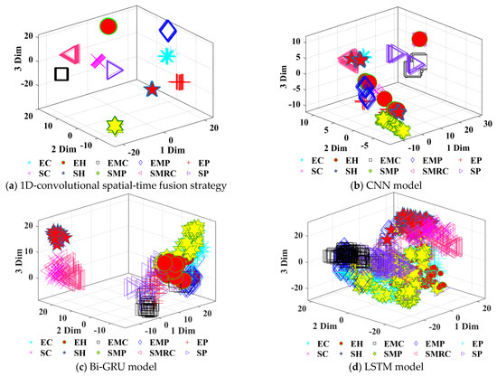
Figure 12.
t-SNE Visualization of the features in each full connection layer with different methods for aero-hydraulic pipeline fault diagnosis.
Figure 12a shows that the 1D-convolutional spatial-time fusion strategy based on the vibration sample data of an aero-hydraulic pipeline can clearly distinguish two types of health states and eight types of fault states in the straight and bent pipeline system. The different types of hydraulic pipeline fault data are distinctly clustered, with relatively high aggregation within clusters and relatively more distance between two clusters of data points. No crossover part is found. It can indicate that the clustering effect is pronounced and essentially achieves the ideal clustering effect.
In Figure 12b, the conventional CNNs model can roughly distinguish 10 types of aero-hydraulic pipeline fault data. The 10 types of data, such as bend middle crater fault, bend middle crack fault, straight pipeline middle crater fault and straight pipeline end crater fault, can form their sub-clusters. At the same time, the aggregation degree within the clusters is relatively inferior. It can also be seen that there is a serious crossover between the three types of sub-clusters, such as hydraulic bend health status, straight pipe intermediate crack status and hydraulic straight pipeline health status, and the distance between the two clusters of data points is relatively close.
As shown in Figure 12c,d, the aero-hydraulic straight pipeline health state can be distinguished relatively clearly based on the Bi-GRU and LSTM model, and the other nine hydraulic pipeline states are not clustered. The aggregation degree is very scattered, which indicates that the clustering effect of conventional CNNs, Bi-GRU and LSTM models is comparatively less effective.
5. Discussion
In this part, firstly, the confusion matrix is used to evaluate the performance of the classification model more comprehensively. And then, in order to avoid chance errors, 10 trials were conducted for each method, and the average value of each type of evaluation index was used as the evaluation index of the classification diagnosis performance of the method. Finally, the superiority of the proposed strategy was verified according to the evaluation indicators.
5.1. Performance Analysis
In this paper, different degrees of pipeline faults are set in the hydraulic straight pipe and hydraulic bend pipe system: a total of 10 kinds of faults. The label of the aviation hydraulic line is shown in Table 3.

Table 3.
Labeling of pipeline status.
With the same data set, the confusion matrix obtained by using the 1D-convolutional spatial-time fusion strategy proposed in this paper to train the aero-hydraulic pipeline fault data are shown in Figure 13.
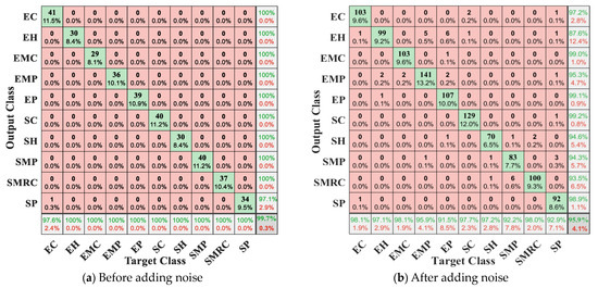
Figure 13.
Confusion matrix based on 1D-convolutional spatial-time fusion strategy for 10 types of hydraulic pipeline data.
After adding noise, the accuracy of the training results of the 1D-convolutional spatial-time fusion strategy for the data set consisting of two types of health states and eight types of fault states of the aero-pipeline listed in Figure 13a is more than 99.7% overall. Among them, for the straight pipeline end pit fault data in the identification of only one sample data identification error, resulting in the overall accuracy of this model 0.3% error rate, the accuracy of this data is 97.1% and the recall rate is 97.6%. In contrast, the evaluation indexes of the other nine sample data were 100%.
When noise was added to the data set, the accuracy of the training results using the 1D-convolutional spatial-time fusion strategy decreased in Figure 13b, with the accuracy rate dropping by 3.8% down to 95.9%. The accuracy rate of the model for single fault identification, in which the hydraulic elbow health status is reduced to 87.6%, and the remaining nine categories of data are above 93.5%. For the recall rate of single fault identification, in which the bend end crater fault, straight pipeline middle pit fault and end pit fault are reduced significantly by 8.5%, 7.8% and 7.1%, respectively. The figures for the remaining seven categories were above 95.9%. It is demonstrated that the proposed method can discriminate pipeline health status and pipeline fault status in both bend and straight pipeline systems, and it can also identify pipeline cracks and crater faults in different locations more accurately. Meanwhile, it is also found that the 1D-convolutional spatial-time fusion strategy still has a high recognition rate under the high-intensity noise interference, and the confusion matrix obtained by using conventional CNNs, Bi-GRU, LSTM, BPNN and SVM is shown in Figure 14, Figure 15 and Figure 16. The description of the hydraulic pipeline data labels is shown in Table 3.
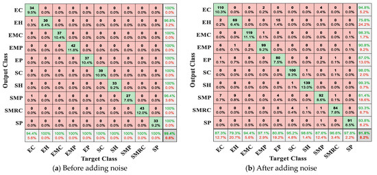
Figure 14.
Confusion matrix based on conventional CNNs model for 10 types of hydraulic pipeline data.
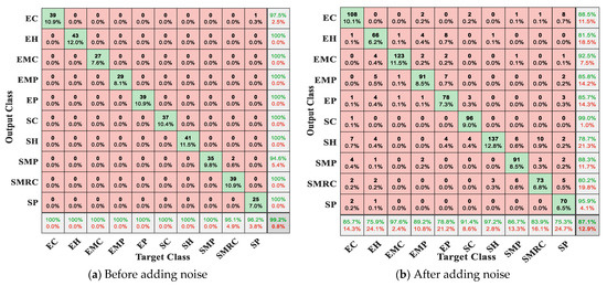
Figure 15.
Confusion matrix based on Bi-GRU model for 10 types of hydraulic pipeline data.
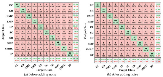
Figure 16.
Confusion matrix based on LSTM model for 10 types of hydraulic pipeline data.
By Figure 14 and Figure 15, it can be seen that, when the noise is added to the data set before, the recognition rate of both conventional CNNs and Bi-GRU models for aero-hydraulic pipelines is kept above 99.2% with high accuracy due to the strong structural advantage of deep learning. However, when noise is added to the data set, the accuracy of both models decreases due to noise interference, which decreases by 7.6% and 12.1%, respectively. The accuracy and recall rates of the conventional CNNs model for single-fault identification are both most significantly reduced for the hydraulic bend health state, by 21% and 20.7%, respectively. The accuracy rate of the Bi-GRU model for single-fault identification is most significantly reduced for the hydraulic straight pipeline health state, by 21.3%. For the recall rate of a single fault, among them the hydraulic bend health state was most significantly reduced, by 24.1%.
From Figure 16, the LSTM models for aero-hydraulic pipelines remained above 92.7% when noise was added to the data set, but when noise was added to the data set, the accuracy of both of these two traditional shallow network models decreased dramatically because of noise interference, by 17.1% and 16.5%, respectively. The accuracy rate of LSTM model for single fault identification, in which the reduction of hydraulic straight pipeline health is very significant, 64.4% reduction. With respect to the recall rate of a single fault, among which the straight pipeline end crack fault and the middle crack fault are reduced significantly, both by 33.3%.
5.2. Result Analysis
Table 4 and Table 5 summarize the training results using the 1D-convolutional spatial-time fusion strategy before and after adding noise to the data set, respectively, for further comparative analysis with the other 5 methods. The performance comparison between the proposed method and the other 5 methods before dyeing noise is shown in Table 4, and the performance comparison between the proposed method and the other 5 methods after dyeing noise is shown in Table 5.

Table 4.
Performance comparison of the proposed strategy with conventional CNNs, Bi-GRU, LSTM, SVM and BPNN, before adding noise.

Table 5.
Performance comparison of the proposed strategy with conventional CNNs, Bi-GRU, LSTM, SVM and BPNN, after adding noise.
It is observed from Table 4 that the 1D-convolutional spatial-time fusion strategy proposed in this paper is significantly better than 2 traditional diagnostic methods such as typical shallow BPNN model and SVM model in terms of diagnostic precision. And when compared with the typical deep learning model such as CNNs, Bi-GRU, and LSTM applied in recent years. The method proposed in this paper has higher average values in four classification performance indexes, such as accuracy, precision, recall and F1-sore, which all reach more than 99.71%.
With the addition of strong noise in the data set, the 1D-convolutional spatial-time fusion strategy still achieves an average of more than 95.8% in 4 classification performance metrics, including accuracy, while the conventional CNNs model, the Bi-GRU model, and the LSTM model both decrease in the average of 4 classification performance metrics, including accuracy, by 7.93%, 12.24%, and 16.06 respectively, as can be seen from Table 5.
Meanwhile, both the BPNN model and the SVM model showed a significant decrease in the average values of four classification performance indexes, including accuracy, by 24.26% and 26.52%, respectively. It indicates that the 1D-convolutional spatial-time fusion strategy can stably identify many different health states of hydraulic pipelines based on the 1D-convolutional spatial-time fusion strategy to comprehensively portray the time-series hydraulic pipeline data with local correlation.
Finally, the robustness of the present model to strong noise signals is confirmed by adding Gaussian noise to the hydraulic pipeline vibration data.
6. Conclusions
This paper proposes an innovative strategy called 1D-convolutional spatial-time fusion for fault diagnosis of aero-engine hydraulic pipelines, and its performance is verified based on measured fault data. This fascinating finding shows that the 1D-Convolutional space-time fusion strategy will apply to the actual condition monitoring of aero-engine hydraulic pipelines to reduce maintenance costs and machine downtime. At least four main conclusions can be drawn from the investigated work:
- (1)
- Due to the complexity and diversity of the structure of the aero-hydraulic pipeline, the fault mechanism of the hydraulic pipeline is relatively complex. An end-to-end aero-hydraulic pipeline fault identification model is established in this paper. To further improve the generalization performance of the proposed strategy and realize its adaptive extraction and classification, the hyperparameters of the proposed model are debugged based on the actual measured pipeline data. This method can effectively avoid the difficulties of insensitive pipeline faults caused by the feature extraction method of manual intervention and provides a novel idea for the intelligent diagnosis of early faults in aviation hydraulic pipelines.
- (2)
- Aiming at the problem of poor model nonlinear fitting ability due to the influence of fluid–structure coupling vibration characteristics and loud external noises. The designed spatial feature fusion module is introduced into the temporal feature fusion module to develop a new spatial-time fusion model, which fully integrates the global and local fault characteristics of hydraulic pipeline data and further improves the anti-interference ability of the model in engineering practice.
- (3)
- To link the current data output with the state information before and after the hydraulic pipeline data, this paper utilizes a bi-directional gated recurrent unit, which can make up for the defects of the single-directional gated recurrent unit model. Then, it is noteworthy that the model can still maintain 95.9% accuracy under Gaussian noise interference, thus verifying that the proposed strategy has better robustness and effectiveness for aero-hydraulic pipeline fault identification.
- (4)
- Compared with traditional CNNs models and advanced Bi-GRU and LSTM models applied in recent years, the average diagnostic accuracy of the proposed strategy exceeds 99.71% in four classification performance indexes, including accuracy, precision, recall and F1-sore. The superiority of the proposed model for pipeline fault identification is further verified, so as to provide a certain scientific reference for the intelligent diagnosis of aero-hydraulic pipeline systems.
While our research has yielded commendable results, it is important to acknowledge that the hydraulic line systems of aircraft engines operate in complex environments with numerous sources of excitation and a significant presence of fixed frequency disturbances. Consequently, future endeavors should focus on developing troubleshooting methods specifically tailored to address aero-hydraulic system faults encountered in real-world space conditions.
In the forthcoming investigations, by dedicating our efforts to exploring troubleshooting methods tailored to actual space pipeline failures in aero-hydraulic systems, we are poised to contribute to the advancement of aviation technology and ensure the utmost safety and reliability in future space missions.
Author Contributions
Conceptualization, T.Y., X.Y. (Xiaoguang Yu) and Q.H.; Methodology, T.Y., G.L. and X.Y. (Xueyin Yang); Software, G.L.; Validation, T.Y., G.L., S.Y. and X.Y. (Xueyin Yang); Formal analysis, T.W. and S.Y.; Investigation, T.Y. and S.Y.; Resources, G.L., T.W. and X.Y. (Xiaoguang Yu); Data curation, T.W., X.Y. (Xueyin Yang) and Q.H.; Writing—original draft, T.Y. and X.Y. (Xueyin Yang); Writing—review & editing, T.Y., X.Y. (Xueyin Yang), X.Y. (Xiaoguang Yu) and Q.H. All authors have read and agreed to the published version of the manuscript.
Funding
This research was supported in part by The National Natural Science Foundation of China (No. 51775257). National Science and Technology Professional Projects (No. J2019-I-0008-0008).
Conflicts of Interest
The authors declare that they have no known competing financial interest or personal relationship that could have appeared to influence the work reported in this paper.
References
- Gao, P.; Yu, T.; Zhang, Y.; Wang, J.; Zhai, J. Vibration analysis and control technologies of hydraulic pipeline system in aircraft: A review. Chin. J. Aeronaut. 2021, 34, 83–114. [Google Scholar] [CrossRef]
- Gao, P.; Zhai, J.; Yan, Y.; Han, Q.; Qu, F.; Chen, X. A model reduction approach for the vibration analysis of hydraulic pipeline system in aircraft. Aerosp. Sci. Technol. 2016, 49, 144–153. [Google Scholar] [CrossRef]
- Tian, J.; Yuan, C.; Yang, L.; Wu, C.; Liu, G.; Yang, Z. The vibration characteristics analysis of pipeline under the action of gas pressure pulsation coupling. Eng. Fail. Anal. 2016, 16, 499–505. [Google Scholar] [CrossRef]
- Yang, T.; Yu, X.; Li, G.; Dou, J.; Duan, B. An early fault diagnosis method based on the optimization of a variational modal decomposition and convolutional neural network for aeronautical hydraulic pipe clamps. Meas. Sci. Technol. 2020, 31, 055007. [Google Scholar]
- Li, Z.; Gao, P.; Tong, K.; Zhao, D.; Liu, J. Research of fault diagnosis method of hydraulic pipeline cracks based on HHT. Comput. Eng. Appl. 2016, 52, 221–226. [Google Scholar]
- Ding, H.; Ji, J.; Chen, L.Q. Nonlinear vibration isolation for fluid-conveying pipes using quasi-zero stiffness characteristics. Mech. Syst. Signal Process. 2019, 121, 675–688. [Google Scholar] [CrossRef]
- Tan, X.; Ding, H.; Chen, L. Nonlinear frequencies and forced responses of pipes conveying fluid via a coupled Timoshenko model. J. Sound Vib. 2019, 455, 241–255. [Google Scholar] [CrossRef]
- Tan, X.; Ding, H. Parametric resonances of Timoshenko pipes conveying pulsating high-speed fluids. J. Sound Vib. 2020, 485, 115594. [Google Scholar] [CrossRef]
- Zang, X.; Liu, W.; Zang, Y.; Zhao, Y. Experimental investigation and optimization design of multi-support pipeline system. Chin. J. Mech. Eng. 2021, 34, 10. [Google Scholar] [CrossRef]
- Ma, Y.; Chen, G. Natural Vibration of a Beam with a Breathing Oblique Crack. Shock. Vib. 2017, 2017, 8045347. [Google Scholar] [CrossRef]
- Bergant, A.; Kruisbrink, A.; Arregui, F. Dynamic Behaviour of Air Valves in a Laige-Scale Pipeline Apparatus. Stroj. Vestn.-J. Mech. Eng. 2012, 58, 225–237. [Google Scholar] [CrossRef]
- Zhu, H.; Wang, W.; Yin, X.; Gao, C. Spectral element method for vibration analysis of three-dimensional pipes conveying fluid. Int. J. Mech. Mater. Des. 2019, 15, 345–360. [Google Scholar] [CrossRef]
- Liu, M.; Wang, Z.; Zhou, Z.; Qu, Y.; Yu, Z.; Wei, Q.; Lu, L. Vibration response of multi-span fluid-conveying pipe with multiple accessories under complex boundary conditions. Eur. J. Mech./A Solids. 2018, 72, 41–56. [Google Scholar] [CrossRef]
- Pavlou, D.G.; Correia, J.A. Dynamic response of pipelines under impact and harmonic loading. Proc. ICE-Marit. Eng. 2019, 172, 15–22. [Google Scholar] [CrossRef]
- Li, J.; Deng, H.; Jiang, W. Dynamic response and vibration suppression of a cantilevered pipe conveying fluid under periodic excitation. J. Vib. Control 2019, 25, 1695–1705. [Google Scholar] [CrossRef]
- Hinton, G.E.; Salakhutdinov, R.R. Reducing the dimensionality of data with neural networks. Science 2006, 313, 504–507. [Google Scholar] [CrossRef]
- Khan, S.; Yairi, T. A review on the application of deep learning in system health management. Mech. Syst. Signal Process. 2018, 107, 241–265. [Google Scholar] [CrossRef]
- Hoang, D.; Kang, H.J. A survey on Deep Learning based bearing fault diagnosis. Neurocomputing 2019, 335, 327–335. [Google Scholar] [CrossRef]
- Mao, W.; Feng, W.; Liang, X. A novel deep output kernel learning method for bearing fault structural diagnosis. Mech. Syst. Signal Process. 2019, 117, 293–318. [Google Scholar] [CrossRef]
- Zhang, W.; Li, C.; Peng, G.; Chen, Y.; Zhang, Z. A deep convolutional neural network with new training methods for bearing fault diagnosis under noisy environment and different working load. Mech. Syst. Signal Process. 2018, 100, 439–453. [Google Scholar] [CrossRef]
- Eren, L.; Ince, T.; Kiranyaz, S. A Generic Intelligent Bearing Fault Diagnosis System Using Compact Adaptive 1DCNN Classifier. J. Signal Process. Syst. 2019, 91, 179–189. [Google Scholar] [CrossRef]
- Chen, Z.; Gryllias, K.; Li, W. Intelligent Fault Diagnosis for Rotary Machinery Using Transferable Convolutional Neural Network. IEEE Trans. Ind. Inform. 2020, 16, 339–349. [Google Scholar] [CrossRef]
- Shang, Z.; Li, W.; Gao, M.; Liu, X.; Yu, Y. An Intelligent Fault Diagnosis Method of Multi-Scale Deep Feature Fusion Based on Information Entropy. Chin. J. Mech. Eng. 2021, 34, 58–76. [Google Scholar] [CrossRef]
- Barcelos, A.S.; Cardoso, A.J.M. Current-Based Bearing Fault Diagnosis Using Deep Learning Algorithms. Energies 2021, 14, 2509. [Google Scholar] [CrossRef]
- Huang, R.; Liao, Y.; Zhang, S.; Li, W. Deep Decoupling Convolutional Neural Network for Intelligent Compound Fault Diagnosis. IEEE Access 2019, 7, 1848–1858. [Google Scholar] [CrossRef]
- Liu, R.; Yang, B.; Zio, E.; Chen, X. Artificial intelligence for fault diagnosis of rotating machinery: A review. Mech. Syst. Signal Process. 2018, 108, 33–47. [Google Scholar] [CrossRef]
- Wang, H.; Li, S.; Song, L. A Novel Convolutional Neural Network Based Fault Recognition Method via Image Fusion of Multi-vibration-signals. Comput. Ind. 2019, 105, 182–190. [Google Scholar] [CrossRef]
- Zhu, X.; Hou, D.; Zhou, P.; Han, Z.; Yuan, Y.; Zhou, W.; Yin, Q. Rotor fault diagnosis using a convolutional neural network with symmetrized dot pattern images. Measurement 2019, 138, 526–535. [Google Scholar] [CrossRef]
- Wang, S.; Xiang, J.; Zhong, Y.; Tang, H. A data indicator-based deep belief networks to detect multiple faults in axial piston pumps. Mech. Syst. Signal Process. 2018, 112, 154–170. [Google Scholar] [CrossRef]
- Pan, Z.; Meng, Z.; Chen, Z.; Gao, W.; Shi, Y. A two-stage method based on extreme learning machine for predicting the remaining useful life of rolling-element bearings. Mech. Syst. Signal Process. 2020, 144, 106899. [Google Scholar] [CrossRef]
- Shao, H.; Jiang, H.; Zhang, H.; Duan, W.; Liang, T.; Wu, S. Rolling bearing fault feature learning using improved convolutional deep belief network with compressed sensing. Mech. Syst. Signal Process. 2018, 10, 743–765. [Google Scholar] [CrossRef]
- Jia, F.; Lei, Y. Deep normalized convolutional neural network for imbalanced fault classification of machinery and its understanding via visualization. Mech. Syst. Signal Process. 2018, 110, 349–367. [Google Scholar] [CrossRef]
- Chen, H.-Y.; Lee, C.-H. Deep Learning Approach for Vibration Signals Applications. Sensors 2021, 21, 3929. [Google Scholar] [CrossRef]
- Kolar, D.; Lisjak, D.; Pajak, M.; Gudlin, M. Intelligent Fault Diagnosis of Rotary Machinery by Convolutional Neural Network with Automatic Hyper-Parameters Tuning Using Bayesian Optimization. Sensors 2021, 21, 2411. [Google Scholar] [CrossRef]
- Lu, S.; Sian, H.; Wang, M.; Kuo, C. Fault diagnosis of power capacitors using a convolution al neural network combined with the chaotic synchronisation method and the empirical mode decomposition method. IET Sci. Meas. Technol. 2021, 15, 551–561. [Google Scholar] [CrossRef]
- Habbouche, H.; Amirat, Y.; Benkedjouh, T.; Benbouzid, M. Bearing Fault EventTriggered Diagnosis using a Variational Mode Decomposition-based Machine Learning Approach. IEEE Trans. Energy Convers 2021, 37, 466–474. [Google Scholar] [CrossRef]
- Zhang, H.; Shi, P.; Han, D.; Jia, L. Research on rolling bearing fault diagnosis method based on AMVMD and convolutional neural networks. Measurement 2023, 217, 113028. [Google Scholar] [CrossRef]
- Yang, Z.; Zhang, J.; Zhao, Z.; Zhai, Z.; Chen, X. Interpreting network knowledge with attention mechanism for bearing fault diagnosis. Appl. Soft Comput. 2020, 97, 106829. [Google Scholar] [CrossRef]
- Zhang, L.; BI, F.; Cheng, J.; Shen, P. Mechanical fault diagnosis method based on attention Bi-GRU. J. Vib. Shock 2021, 40, 113–118. [Google Scholar]
- Qin, C.; Wu, R.; Huang, G.; Tao, J.; Liu, C. A novel LSTM-autoencoder and enhanced transformer-based detection method for shield machine cutterhead clogging. Sci. China Technol. Sci. 2023, 66, 512–527. [Google Scholar] [CrossRef]
- Yan, H.; Bai, H.; Zhan, X.; Wu, Z.; Wen, L.; Jia, X. Combination of VMD Mapping MFCC and LSTM: A New Acoustic Fault Diagnosis Method of Diesel Engine. Sensors 2022, 22, 8325. [Google Scholar] [CrossRef]
- Xu, K.; Ba, J.; Kiros, R.; Cho, k.; Courville, A.; Salakhutdinov, R.; Zemel, R.; Bengio, Y. Show, attend and tell: Neural image caption generation with visual attention. Proc. Int. Conf. Mach. Learn. 2015, 2048–2057. [Google Scholar]
- Zhu, H.; Wang, X.; Rui, T.; Zhang, Y.; Li, Y. Machinery fault diagnosis based on shift invariant CNN. J. Vib. Shock. 2019, 38, 45–52. [Google Scholar]
- Abdeljaber, O.; Avci, O.; Kiranyaz, S.; Gabbour, M.; Inman, D. Real-time vibration-based structural damage detection using one-dimensional convolutional neural networks. J. Sound Vib. 2017, 388, 154–170. [Google Scholar] [CrossRef]
- Zhang, C.; Peng, K.; Dong, J.; Miao, L. A comprehensive operating performance assessment framework based on distributed Siamese gated recurrent unit for hot strip mill process. Appl. Soft Comput. 2023, 132, 109889. [Google Scholar] [CrossRef]
- Wang, Y.; Wang, J.; Fan, S.; Wang, Y. Quick intention identification of an enemy aerial target through information classification processing. Aerosp. Sci. Technol. 2023, 132, 108005. [Google Scholar]
- An, J.; Ai, P.; Xu, S.; Liu, C.; Xia, J.; Liu, D. An intelligent fault diagnosis method for rotating machinery based on one-dimensional convolutional neural network. J. Nanjing Univ. (Nat. Sci.) 2019, 55, 133–142. [Google Scholar]
- Xiang, S.; Qin, Y.; Luo, J.; Pu, H. Spatiotemporally Multi-differential Processing Deep Neural Network and its Application to Equipment Remaining Useful Life Prediction. IEEE Trans. Ind. Inform. 2022, 18, 7230–7239. [Google Scholar] [CrossRef]
- Chen, Z.; Mauricio, A.; Li, W.; Gryllias, K. A deep learning method for bearing fault diagnosis based on Cyclic Spectral Coherence and Convolutional Neural Networks. Mech. Syst. Signal Process. 2020, 140, 106683. [Google Scholar] [CrossRef]
- Buchaiah, S.; Shakya, P. Bearing fault diagnosis and prognosis using data fusion based feature extraction and feature selection. Measurement 2022, 188, 110506. [Google Scholar] [CrossRef]
- Wang, S.; Yang, K.; Shi, Y.; Yang, F.; Zhang, H.; Ma, Y. Prediction of Over-the-Horizon Electromagnetic Wave Propagation in Evaporation Ducts Based on the Gated Recurrent Unit Network Model. IEEE Trans. Antennas Propag. 2023, 71, 3485–3496. [Google Scholar] [CrossRef]
- Lee, G.S.; Kim, S.; Bae, S. Efficient Design Method for a Forward-Converter Transformer Based on a KNN–GRU–DNN Model. IEEE Trans. Power Electron. 2023, 38, 73–78. [Google Scholar] [CrossRef]
- Chen, C. Text Categorization Based on Deep Belief Network. Comput. Syst. Appl. 2015, 24, 121–126. [Google Scholar]
- Yan, G.; Tan, X.; Lü, F. Prediction of aero engine fan noise based on Boeing algorithm. Sci. Technol. Eng. 2018, 18, 154–159. [Google Scholar]
- Li, D.; Yang, X. Research on low noise design of a large bypass ratio turbofan engine fan. Acoust. Technol. 2013, 32, 157–160. [Google Scholar]
- Sun, S.; Zhang, T.; Li, Q.; Wang, J.; Zhang, W.; Wen, Z.; Tang, Y. Fault Diagnosis of Conventional Circuit Breaker Contact System Based on Time–Frequency Analysis and Improved Alex-Net. IEEE Trans. Instrum. Meas. 2021, 70, 3508512. [Google Scholar]
- Yao, Q.; Wang, R.; Fan, X.; Liu, J.; Ye, L. Multi-class Arrhythmia detection from12-lead varied length ECG using Attention-based Time-Incremental Convolutional Neural Network. Inf. Fusion 2020, 53, 174–182. [Google Scholar] [CrossRef]
Disclaimer/Publisher’s Note: The statements, opinions and data contained in all publications are solely those of the individual author(s) and contributor(s) and not of MDPI and/or the editor(s). MDPI and/or the editor(s) disclaim responsibility for any injury to people or property resulting from any ideas, methods, instructions or products referred to in the content. |
© 2023 by the authors. Licensee MDPI, Basel, Switzerland. This article is an open access article distributed under the terms and conditions of the Creative Commons Attribution (CC BY) license (https://creativecommons.org/licenses/by/4.0/).