Abstract
The high-energy-level dynamic compaction method is widely used in various foundation treatment projects, but its reinforcement mechanism still lags behind the practice. In view of this, a three-dimensional fluid–solid coupling dynamic analysis model was established on the basis of the FDM–DEM coupling method. The variation trends of crater depth, soil void ratio, vertical additional dynamic stress, and pore water pressure during the process of dynamic compaction were analyzed. The results indicate that the curvature of the crater depth fitting curve gradually decreases with the increase in strike times, tending to a stable value. The initial particle structure is altered by the huge dynamic stress induced by dynamic compaction. As strike times increase, the soil void ratio decreases gradually. The vertical additional dynamic stress is the fundamental reason resulting in foundation compaction. Precipitation preloading before dynamic compaction can improve the reinforcement effect of dynamic compaction, making up for the deficiency that the vertical additional dynamic stress attenuates rapidly along the depth direction. The simulated CPT results illustrate that the modulus of foundation soil can be increased by 3–5 times after dynamic compaction. The research results can provide important reference for similar projects.
Keywords:
foundation treatment; high-energy dynamic compaction; FDM–DEM coupling; granular soil; vertical dynamic stress; effective reinforcement depth; reinforcement mechanism MSC:
65P99; 70-10; 74F10
1. Introduction
Dynamic compaction (DC) is an energy-saving and environmentally friendly foundation treatment method. In addition, it has a significant cost-effective advantage over conventional foundation treatment methods [1]. With the rapid development of large infrastructure and coastal land construction projects, the high-energy-level dynamic compaction method emerges to deal with the increasingly complex conditions [2]. In the foundation treatment of marine reclamation land and backfilled granular soil, due to the loose soil quality and large depth of backfill, it takes more than 6 months or even several years to complete the foundation treatment with the preloading method. However, the high-energy dynamic compaction can improve the bearing capacity of foundation in place at one time, shortening the construction period to several months [3].
Dynamic compaction is a design method with double control of deformation and bearing capacity, with an emphasis on deformation control, especially for high-energy dynamic compaction. As a systematic engineering, the following parameters need to be considered in the design of dynamic compaction: the size of the hammer, the energy level of dynamic compaction, the spacing and arrangement of compaction points, the number of strikes, the standard of hammer retraction, the crater depth, the effective reinforcement depth, and the influence range of dynamic compaction. Since dynamic compaction involves complicated transient dynamic response issues, studies on dynamic compaction are mainly conducted by numerical simulations [4,5,6,7,8,9,10,11,12,13,14,15,16,17,18,19,20], model tests [21,22,23], and field tests [24,25,26,27,28,29,30,31,32]. Numerical simulation methods adopted by scholars principally include the finite element method (FEM) [4,5,6,7,8,9,10,11], finite difference method (FDM) [12,13,14], discrete element method (DEM) [15,16], and coupling calculation of various numerical simulation methods [17,18,19,20]. Wang et al. [4] established a 2D axisymmetric numerical model in LS-DYNA to investigate the influence of dynamic compaction on the ground surface deformation. On the basis of the results obtained, a forecast model was proposed to assess ground deformation under dynamic compaction. However, the effect of excess pore water pressure generated by DC was not considered in the numerical model. Zhou et al. [5] analyzed the improvement on saturated foundation under dynamic compaction through a dynamic fluid–solid coupled finite element method with soil cap model. The results illustrated that it is crucial to lower the groundwater table before implementing dynamic compaction. Yao et al. [7] performed a parametric study on the densification of sandy soil by conducting three-dimensional finite element analyses. Lastly, a design procedure was proposed to predict the soil relative density associated with dynamic compaction projects. Li et al. [8] investigated the improvement mechanism of DC in saturated soil of a weak layer with high levels of groundwater by performing fluid–solid coupling simulations. The results indicated that, in order to achieve a better compaction effect during DC, the groundwater table should be lowered by dewatering or adding a drainage layer between the ground surface and the groundwater. Chen et al. [12] established a modified constitutive model considering the kinematic hardening effect in FLAC3D under the framework of the Mohr–Coulomb criterion to describe gravelly soils by grain crushing tests and large-scale direct shear tests. However, the dynamic loading was expressed as triangular loading, which could not accurately reflect the actual load effect. Yao et al. [13] chose two sites with different groundwater tables to assess the variation of excess pore pressure during DC and performed a numerical analysis by FLAC3D to examine the liquefaction potential of silty ground. The results demonstrated that a higher water table would lead to higher potential for the ground liquefaction. However, the Finn model adopted in the numerical model could not capture the modulus increase induced by DC. Ma et al. [15] simulated the dynamic compaction process of gravel soil foundation using PFC2D/PFC3D. The findings revealed that the maximum influence depth of the dynamic compaction obtained by the three-dimensional analyses using PFC3D was lower than that by the two-dimensional analyses using PFC2D. However, the accuracy of the results was affected to some extent by using round and spherical hammers. Li et al. [16] studied the micro-dynamic reinforcement mechanism of gravel soil through PFC2D. The results showed that the coordination number of soil particles increased, and the porosity decreased. However, the tamping energy was only 3000 kN·m, and the porosity in the two-dimensional mode was significantly different from that in the three-dimensional mode, which is difficult to promote in a wider application field.
In numerical simulation methods, FEM can only analyze small deformation issues, because, once the displacement gets too large, the mesh of finite elements will be distorted, resulting in inaccuracy of calculation results or nonconvergence of the calculation process. A substantial displacement of soil occurs instantly when a hammer strikes the ground. Therefore, it is difficult to obtain accurate calculation results by using the finite element method to analyze the displacement and additional stress variations induced by high-energy dynamic compaction. The DEM can simulate the large deformation of soil particles, which has unique advantages in reflecting the micromechanical behavior of soil, especially for backfilled granular soil. However, the DEM decomposes the soil mass into a series of particles in space and carries out iterative calculation over time, which requires a huge amount of computation and is far less efficient than continuum methods. As a result, the DEM is limited in model size or can only simplify the three-dimensional problem into a two-dimensional problem analysis. The finite difference method (FDM) provides an approach to solve the large deformation problem in a continuum. However, the necessity for mesh precision is significant when dealing with the dynamic problem of local impact load, and it is still difficult to fully reflect the local punching characteristics around the hammer. With the continuous development of numerical analysis technology, continuum–discrete coupling calculation methods, such as FDM–DEM coupling, provide a new possibility to solve the dynamic problem of local large deformation [33,34,35,36].
At present, only a few scholars have simulated the dynamic compaction process using a continuum–discrete coupling method. Jia et al. [17] reproduced the dynamic densification process of granular soils by analyzing the soil displacement field, motion of tracer particles, and evolution of local porosity through PFC/FLAC coupled simulation, but the research was presented for issues with two-dimensional planes. Wang et al. [18] established a 3D continuum–discrete coupling model to simulate the hammer–soil interaction process. The results illustrated that ellipsoidal compaction bands were formed inside the punching surface, and shear bands were formed outside the punching surface. However, the tamping energy was only 2000 kN·m. Meanwhile, the numerical model only considered the effect of one strike, ignoring the characteristics of multiple strikes, as well as the influence of groundwater. Jia et al. [19] introduced a coupled three-dimensional discrete element–finite difference simulation of dynamic compaction. The results indicated that the soil undergoes a transient weakening process induced by dynamic stress propagation. Allocating higher compaction energy to the bearing capacity mechanism could improve the efficiency of dynamic compaction. However, for dynamic analysis, the coupling model did not adopt a suitable boundary to absorb dynamic waves. It is not sufficiently clear how the crater changes during DC. Wang et al. [20] presented a 3D FEM–SPH coupling model in LS-DYNA. It was found that the penetration of the hammer increased with the increase in tamping energy. The coupled simulation method could deal with the DC problem even if the tamping energy was extremely high.
In practice, the design parameters still depend on engineering experience, especially the vertical additional dynamic stress and effective reinforcement depth with a high energy level. Most scholars primarily place emphasis on the influence of one DC on soil displacement, with few studies being performed on the vertical additional dynamic stress propagation law along depth and the effective reinforcement depth during high-energy-level dynamic compaction. Meanwhile, in the aforementioned studies, continuum–discrete two-phase media were rarely adopted to implement a dynamic simulation of high-energy dynamic compaction based on fluid–solid coupling, which is highly consistent with reality. In view of this, it is of great significance to study the reinforcement mechanism of high-energy-level dynamic compaction, which can help us better predict the effect of foundation treatment by high-energy dynamic compaction.
The outline of this paper is as follows: firstly, the soft soil foundation treatment project of Taiping Bay Cooperative Innovation Zone in Wafangdian City, Dalian City is taken as an engineering background. The foundation treatment scheme is determined on the basis of the geological conditions. Secondly, a three-dimensional continuum–discrete fluid–solid coupling dynamic analysis model is established using Particle Flow Code (PFC) and Fast Lagrangian Analysis of Continua (FLAC). The procedure of a hammer’s free fall from a given height to strike the ground is performed in clumps. The cumulative crater depth, the variation of soil void ratio, the changing process of vertical additional dynamic stress at different positions along the depth, and the pore water pressure after dynamic compaction were obtained. Lastly, the cone tip resistance before and after dynamic compaction at the center line of the crater was obtained by means of simulated static cone penetration tests (CPTs). Compared with field tests, the reliability of soil particle microparameters and the effectiveness of high-energy dynamic compaction in foundation treatment were verified.
2. FDM–DEM Coupling Numerical Simulation
2.1. Project Overview
Taiping Bay Cooperation Innovation Zone is located in the north of Dalian on the Bohai Sea side of Liaodong Peninsula, 240 km from Shenyang in the north and 106 km from Dalian in the south. The port area is about 13.86 km2. The port was originally the sea area, and the existing land was composed of new dredger fill. The proposed site is located in the coastal, shoal zone. The location of the foundation treatment project is shown in Figure 1. The site is backfilled with granular soils at present, and the average backfill thickness is 7.5 m. The current situation of the proposed site is shown in Figure 2. In Figure 2, the western side of the proposed site is close to the coastline.
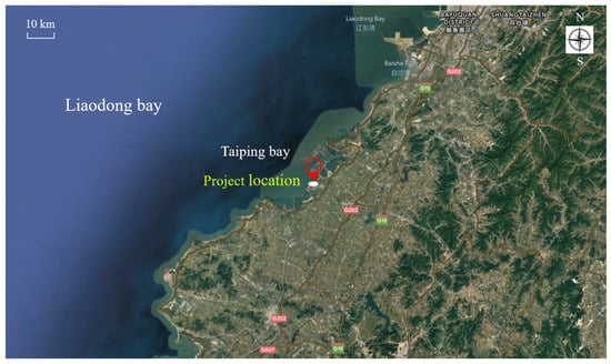
Figure 1.
Location of the foundation treatment project.
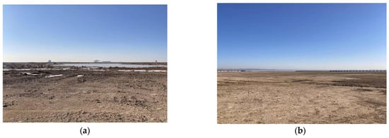
Figure 2.
Current situations of the proposed site: (a) western side; (b) southern side.
Comprehensive exploration methods combining drilling sampling, standard penetration tests (SPTs), dynamic penetration tests (DPTs), static cone penetration tests (CPTs), and laboratory soil tests were applied to investigate the soil layer on site. The site’s groundwater level is primarily affected by seawater, and the groundwater level is basically located at 3 m below the ground surface. The physical and mechanical properties of site soils are shown in Table 1. It should be noted that soil layer 3 contains silty sand interlayer and no mud; hence, this soil layer still has a certain degree of hardness which can be described by SPT.

Table 1.
Physical and mechanical properties of site soils.
2.2. Foundation Treatment Scheme
According to the geological conditions of the site and engineering experience, the available foundation treatment schemes for each soil layer to be treated include the dynamic compaction method, substitution method, vacuum preloading method, and surcharge preloading method. Among them, the substitution method is impracticable due to its substantial material consumption and poor economy. Partial substitution can be carried out in some special areas such as field roads. The project site belongs to the upper hard and lower soft strata, and the soft soil layer is buried deep. In order to reduce the post-construction settlement, the drainage plate needs to be set up at a greater depth, and the preloading period needs to be longer. Meanwhile, higher requirements are put forward for the machine’s insertion capacity. Therefore, the construction periods for the vacuum preloading method and the surcharge preloading method are excessively long, and the expenses are considerable.
The dynamic compaction method has higher construction efficiency, has lower project cost, can greatly shorten the construction period, and has a good foundation treatment effect. In addition, the huge shock wave caused by high-energy-level dynamic compaction can change the original structure of granular soil and reduce the soil void ratio. Under the impact of dynamic compaction, the granular soil of the upper hard layer will be squeezed into the lower dredger fill soft soil layer to increase the content of coarse particles in the deep soft soil layer, enhancing the bearing capacity of the entire foundation significantly. According to the previous engineering experience and specification suggestions, in order to make the effective reinforcement depth of dynamic compaction exceed the thickness of hard layer and affect the soft soil filled below, the dynamic compaction energy level of this project was set to 8000 kN·m.
2.3. FDM–DEM Coupling Technique
DEM can realize dynamic large deformation simulation based on Newton’s second law, but the size limitation of the numerical model affects the accuracy of the calculation results. FDM can reflect pore pressure changes, dynamic wave propagation, and continuous displacement trends, expand model size, and eliminate dynamic wave reflection through the free field boundary. The coupling calculation makes up for the corresponding shortcomings. In the FDM–DEM coupling calculation, FLAC3D was used to simulate the mechanical behavior of the medium in the continuous domain macroscopically, while PFC3D was used to simulate the mechanical behavior of the medium in the discrete domain microscopically. The flowchart for FDM–DEM coupling calculation is shown in Figure 3.
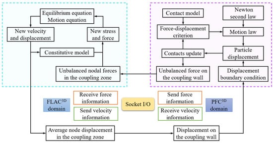
Figure 3.
Flowchart for FDM–DEM coupling calculation.
The process of FDM-DEM coupling is to follow the principle of virtual work of continuum element nodes and Newton’s second law of discrete element particles in the iterative calculation process. The data such as force and velocity are continuously transmitted through the coupling boundary. The consistency and continuity of the calculated data in the discrete domain and the continuum domain are ensured by timestep control, so as to realize the comprehensive analysis of the mechanical behavior of the medium from the perspective of continuum and discrete macro–micro synergy. At each calculation step, the continuum domain element node transmits the velocity to the discrete domain boundary particles, and then generates displacement and contact force inside the discrete domain material. The generated force is also transmitted to the element nodes of the continuum domain through the particles of the coupling boundary to complete the coupling loop operation.
At each cycle of PFC3D, a force–displacement criterion is applied to each contact, controlling the motion of particles according to Newton’s second law, while constantly updating the position of the particles and the wall. The unbalance force on the coupling wall is transmitted to FLAC3D through the embedded Socket I/O interface. After obtaining the new stress and force, the new velocity and displacement are calculated by calling the equilibrium equation (motion equation), and the node displacement on the coupling area is transformed into a new displacement boundary condition through the Socket I/O interface. The displacement of particles in the discrete domain is made, and the cyclic calculation is carried out successively.
2.4. The 3D FDM–DEM Coupling Numerical Model
In the dynamic analysis of geotechnical engineering, the fixed boundary conditions commonly used in static analysis will cause a reflection of dynamic waves on the model boundary, and this phenomenon can be reduced by adopting a wider model range [37,38]. For this reason, a larger model size was used in this numerical simulation, with a length and width of 40 m and height of 21 m. Free field boundaries were set at the four sides and four corners of the model, and a quiet boundary was set at the bottom of the model, which could eliminate the reflection of dynamic waves at the model bottom and achieve an effect similar to an infinite range boundary. The granular soil in the central area with a height of 5 m and a diameter of 5 m was discretized and surrounded by continuum. The size radius of the soil particles was between 0.035 and 0.04 m. In the initial stage, 238,214 balls were generated in the discrete domain. The three-dimensional FDM–DEM coupling numerical model is shown in Figure 4.
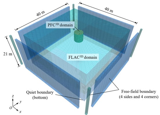
Figure 4.
Three-dimensional FDM–DEM coupling numerical model.
In order to simulate the process of dynamic compaction more realistically, the clump composed of pebbles was used to establish the actual size model of the hammer, which could realize the free fall motion of the hammer under the gravity. The hammer weighed 38.288 t, with a diameter of 2.5 m, a height of 1 m, and a density of 7800 kg/m3. The three-dimensional hammer model is shown in Figure 5.
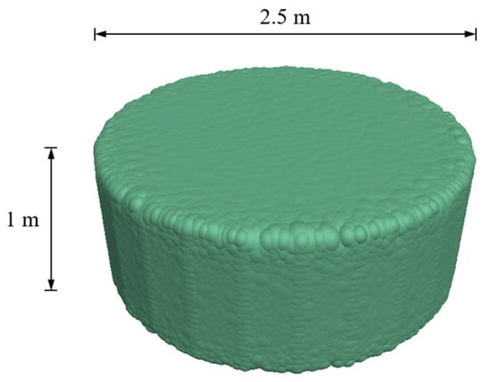
Figure 5.
Three-dimensional hammer model.
The linear parallel bond model was a contact constitutive model proposed by Potyondy [39] to represent the bond characteristics between particles, which could reflect the microscopic contact characteristics of rock and soil. The continuum adopted the Mohr–Coulomb constitutive model. The linear parallel bond constitutive model was used for the discrete medium. The microscopic parameters in the coupled numerical model are shown in Table 2. It is significant to note that the ball–wall parallel-bond strengths were set to be larger than normal to ensure that the balls at the boundary remained bonded to neighboring zones. The model parameters in Table 2 were verified by comparing the simulated CPT tests with the field CPT results.
Table 2.
Microscopic parameters in FDM–DEM coupled numerical model.
A flowchart of the methodology is shown in Figure 6.
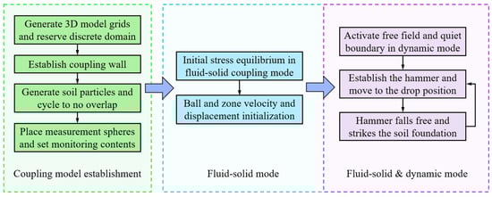
Figure 6.
Flowchart of the methodology.
3. Numerical Analysis Results
In order to reduce the impact of groundwater on the reinforcement effect of dynamic compaction, the foundation treatment scheme considered vacuum well point dewatering to drop the groundwater level from 3 m below the ground surface to 9 m below the ground surface. Before dynamic compaction, the groundwater level dropped to 9 m below the ground surface. The dynamic compaction process is shown in Figure 7, where h is the hammer drop height.
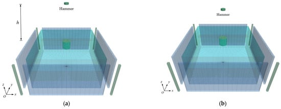
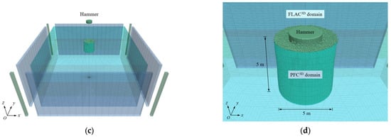
Figure 7.
Dynamic compaction process: (a) release from rest; (b) accelerating due to gravity; (c) approaching ground surface; (d) hammer–soil impact.
3.1. Crater Depth
According to the site strata and foundation treatment requirements, the 8000 kN·m dynamic compaction energy level was adopted to carry out continuous eight strikes at the same tamping point. The height at which the hammer was released freely from rest was 21.3 m. In the last strike of dynamic compaction, the changing process of hammer drop distance and hammer velocity with time is shown in Figure 8 and Figure 9.
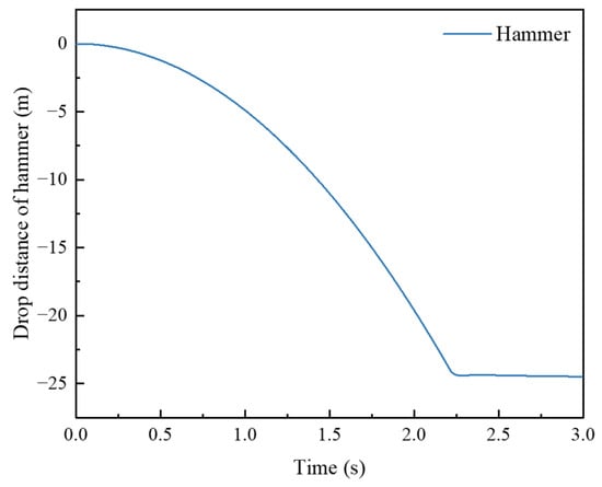
Figure 8.
Changing process of hammer drop distance with time.
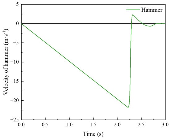
Figure 9.
Changing process of hammer velocity with time.
According to the calculation results of Figure 9, the instantaneous hammer–soil contact time was 50 ms at which point the speed of the hammer decreased to zero.
The vertical displacement contours of the crater after each strike are shown in Figure 10. It can be seen from Figure 10 that, with the increase in the number of strikes, the crater depth gradually increased. Due to the huge impact energy caused by DC, the soil around the hammer was squeezed after each strike, with some soil around the hammer exhibiting a certain degree of splash. A little uplift appeared on the ground surface around the crater. After removing the hammer, the surrounding soil progressively slid into the crater.
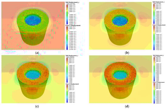
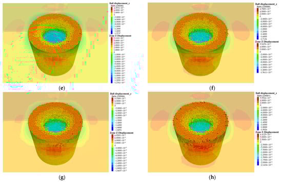
Figure 10.
Vertical displacement of crater (m): (a) first strike; (b) second strike; (c) third strike; (d) fourth strike; (e) fifth strike; (f) sixth strike; (g) seventh strike; (h) eighth strike.
The variations of the cumulative settlement at different depths of the tamping point center with the number of strikes are shown in Figure 11.
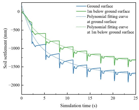
Figure 11.
Soil settlement at different depths in crater center.
Figure 11 describes the relationship between crater depth and strike times. Initially, backfilled granular soil would produce a certain amount of settlement under gravity. The soil settlement caused by the first strike was the maximum due to the large soil void ratio before dynamic compaction. The instant rebound at the crater bottom after the first removal of the hammer was small. With the increase in strike times, the instant rebound at the moment when the hammer was removed increased gradually. However, with the increase in strike times, the resilience of soil stabilized after hammer removal first increased and then decreased gradually. The reason is that there were large voids in the soil at first, and the particles were not wedged tightly. The first strike changed the soil from loose to compact. As the soil was gradually compacted, the resilience of he foundation was enhanced. However, the enhancement of resilience indicates that the compaction degree did not reach the requirement of foundation treatment. When the number of strikes reached seven and eight, the soil settlement of a single strike was reduced, and the rebound in the process of soil stabilization after hammer removal was close to zero, demonstrating that the soil foundation reached a satisfying compaction state at this time. In practical engineering, the standard of hammer retraction is determined by the average settlement in the crater of the last two strikes. When the dynamic compaction energy E of each strike is between 8000 kN·m and 12,000 kN·m, the average settlement in the crater of the last two strikes should be less than 200 mm. According to Figure 11, the total crater depth was 1669 mm, the soil settlement at the crater surface in the first strike was 460.7 mm, and the soil settlement at the crater surface in the last strike was 28.8 mm, meeting the standard of hammer retraction. Polynomial fitting of the soil settlement curves revealed that the curvature of the fitting curve gradually decreased, indicating that the foundation’s bearing capacity increased progressively with the increase in strikes of dynamic compaction and eventually tended to a stable value.
3.2. Soil Void Ratio
The soil void ratio e variations at different depths were monitored by placing measurement spheres in the discrete domain of the FDM–DEM coupled model. The principle of measurement spheres is to measure the volume of particles in the sphere domain and calculate the porosity. Then, the soil void ratio is obtained by the relationship between porosity and void ratio. The radius of the measurement sphere was 400 mm, and the centers of the sphere were distributed at −2 m, −3 m, and −4 m. The changing process of soil void ratio at different depths during dynamic compaction is shown in Figure 12.
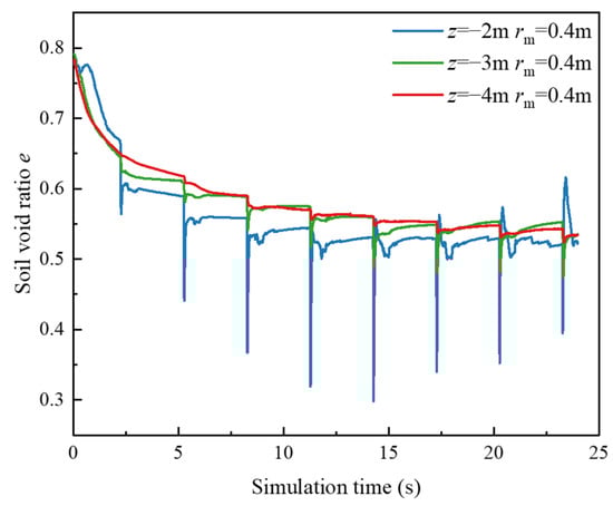
Figure 12.
Changing process of soil void ratio at different depths.
It can be seen from Figure 12 that, with the increase in strike times, the soil void ratio decreased gradually, and the soil void ratio reached the minimum value at the moment when the hammer contacted the soil instantaneously. It should be pointed out that the void ratio monitored at z = −2 m had an upward trend after the fifth strike. The reason is that the nearest distance between the measurement sphere and the surface was 1.6 m, and the crater depth at this time exceeded 1.6 m, resulting in excess void on the upper part of the measurement sphere. The actual trend was still that the soil void ratio gradually decreased. Through calculation and analysis, it was concluded that, after eight strikes of dynamic compaction, the final void ratio of granular soil could be reduced from 0.790 to 0.523. The soil void ratio could be reduced by 33.8%.
3.3. Vertical Additional Dynamic Stress
The vertical additional dynamic stress is the fundamental reason resulting in foundation compaction. The effective reinforcement depth of dynamic compaction can be deduced from the maximum propagation depth of vertical additional dynamic stress. The vertical additional dynamic stress can be obtained by recording the total vertical stress through measurement spheres and deducting the self-weight stress at the corresponding position. Measurement spheres with a radius of 200 mm were arranged vertically every 1 m in the discrete domain. The variation of the vertical additional dynamic stress at different depths in the discrete domain with strike times of dynamic compaction is shown in Figure 13.
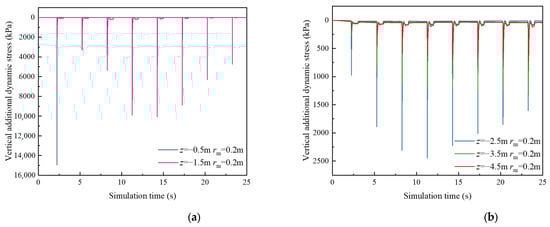
Figure 13.
Variation trends of the vertical additional dynamic stress at different depths: (a) range from −2.0 m to 0 m; (b) range from −5.0 m to −2.0 m.
It can be seen from Figure 13 that the maximum vertical additional dynamic stress decreased with the increase in depth, among which the maximum vertical additional dynamic stress at 0.5 m below the surface caused by the first strike was 14,953.2 kPa. The maximum vertical additional dynamic stress at 1.5 m below the surface was 2305.5 kPa, which decreased by 84.58% compared with that at z = −0.5 m. The maximum vertical additional dynamic stress at 2.5 m below the surface was 972.7 kPa, which decreased by 57.8% compared with that at z = −1.5 m. In Figure 10, the maximum vertical additional dynamic stress in part of the measurement spheres gradually decreased in the later period of dynamic compaction, which was caused by the decrease in the number of particles inside the measurement spheres as the crater depth increased. The results indicate that the vertical additional dynamic stress caused by dynamic compaction attenuated rapidly along the depth. When closer to the ground surface, the attenuation of vertical additional dynamic stress was more obvious.
Meanwhile, the fluctuations of the vertical additional dynamic stress of soil in the discrete domain shown in Figure 13 were obvious, indicating that the discrete domain within 5 m below the ground surface was in the effective reinforcement range of dynamic compaction. In order to further study the maximum effective reinforcement depth that the dynamic compaction energy level of 8000 kN·m could achieve onsite, the variation trends of vertical dynamic stress at the distance between −14 m and −9 m from the ground surface in continuum are shown in Figure 14. The vertical dynamic stress in Figure 14 includes the initial self-weight stress.
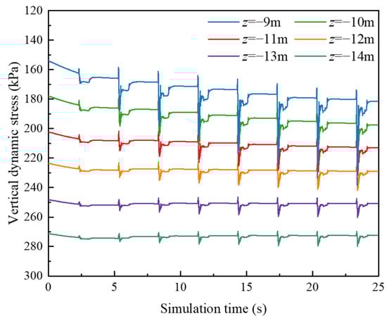
Figure 14.
Variation trends of vertical dynamic stress in continuum.
From Figure 14, it can be seen that the maximum vertical dynamic stress at 9 m below the ground surface during the dynamic compaction process could exceed the initial gravity stress at 12 m below the ground surface, indicating that the dynamic compaction continued to have the ability to compact the foundation soil at 9 m below the ground surface. Similarly, the maximum vertical dynamic stress at 11 m below the surface could also approach the initial self-weight stress at 12 m below the surface, while the fluctuations between the maximum vertical dynamic stress and the self-weight stress at −14 m to −12 m were not obvious. It could be determined that the maximum effective reinforcement depth hd of 8000 kN·m dynamic compaction energy level at this site was −11 m.
The effective reinforcement depth hd of dynamic compaction can also be estimated using Ménard’s empirical formula [1]:
where M is the mass of the hammer (t), h is the drop height (m), and α is a coefficient depending on the properties of foundation soil. For granular soil, the value of α is 0.5. A higher energy per strike results in a lower value of α [40]. Assuming that the reduction coefficient of α is 0.8, the effective reinforcement depth calculated using Menard’s modified formula is 11.42 m, which is in good agreement with the effective reinforcement depth of 11 m calculated by the FDM–DEM coupled numerical model.
hd = α(Mh)1/2,
3.4. Pore Water Pressure
After eight strikes of dynamic compaction, the pore water pressure at the site is shown in Figure 15.

Figure 15.
Pore water pressure at the site after eight strikes of dynamic compaction (mPa).
It can be seen from Figure 15 that the pore water pressure below the crater only increased slightly after dynamic compaction. Therefore, dewatering before dynamic compaction can significantly reduce the instantaneous increase in pore pressure induced by vertical additional dynamic stress. The dewatering depth should be determined according to the initial water level of the site and the dynamic compaction energy level. According to the numerical analysis results, it is generally accepted that the reduction in groundwater level to the effective reinforcement depth of the dynamic compaction can avoid the repeated increase in pore water pressure during the dynamic compaction process and reduce the waiting time for pore water pressure dissipation.
3.5. Total Reinforcement Pressure
Before dynamic compaction, the vacuum well point tubes and tube wells were set for dewatering preloading. As a result, the preloading load could be enhanced by decreasing groundwater, and the increase in pore water pressure could also be decreased during DC. In the dewatering dynamic compaction project, the total reinforcement pressure could be divided into preloading pressure of dewatering in the early stage and vertical additional dynamic stress pressure of dynamic compaction in the later stage. Both of them performed more effectively together to increase the reinforcement pressure and depth of foundation treatment. By superimposing the dewatering pressure and the maximum vertical additional dynamic stress of dynamic compaction, the total reinforcement pressure is shown in Figure 16.
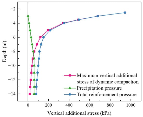
Figure 16.
Total reinforcement pressure.
As can be seen from Figure 16, the dewatering preloading induced by groundwater descending from z = −3 m to z = −9 m was trapezoidal. The vertical additional dynamic stress induced by dynamic compaction decreased rapidly along the depth. The superposition of both could increase the reinforcement effect on deep soil, making up for the limited reinforcement effect of dynamic compaction on deep soil.
3.6. Simulated Static Cone Penetration Tests
In order to verify the reinforcement effect of dynamic compaction on foundation soil, the PFC walls were used to establish a static cone penetration model. The cone tip angle was 60°, the diameter was 43.7 mm, and the penetration velocity was 1.2 m/min. The cone tip resistance qc along the depth direction was recorded during the penetration process. The simulated static cone penetration tests were carried out in the crater center before and after dynamic compaction. The penetration process of static cone penetration after dynamic compaction is shown in Figure 17. The comparison of simulated static cone penetration tests before and after dynamic compaction is shown in Figure 18.
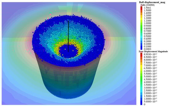
Figure 17.
Penetration process of CPT after dynamic compaction (m).
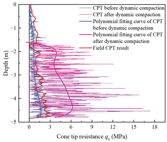
Figure 18.
Comparison of simulated CPTs before and after dynamic compaction.
The simulated results of CPT before dynamic compaction had a good agreement with the field CPT results, verifying the reliability of the numerical calculation parameters. It should be pointed out that, due to the computational efficiency of discrete elements, it is difficult for the particle size to be completely consistent with the size of real soil particles; hence, the cone tip resistance would be zero intermittently in the process of simulating CPT. Therefore, the simulated CPT result was slightly lower than the field CPT result. It can be seen from the comparison results that the simulated results of CPT after dynamic compaction were about 3–5 times higher than those before dynamic compaction. The results illustrate that the modulus of foundation soil could be increased by about 3–5 times after eight strikes of 8000 kN·m high-energy-level dynamic compaction.
4. Conclusions
This study established a three-dimensional fluid–solid coupling dynamic analysis numerical model based on the FDM–DEM coupling method. Clumps were adopted to realize the multiple dynamic simulation of a hammer’s free-falling compaction on foundation soil from a certain height. The reinforcement mechanism of high-energy-level dynamic compaction was studied. The main conclusions are as follows:
- (a)
- The FDM–DEM coupling method was adopted to realize the three-dimensional refined modeling of continuum–discrete coupling, effectively enlarging the model size, reflecting local large deformation during DC, and improving the efficiency of numerical calculation. The 3D coupled model realized the comprehensive analysis of the mechanical behavior of the medium from the perspective of continuum and discrete macro–micro synergy. Meanwhile, a free field boundary and quiet boundary were applied to eliminate the influence of dynamic wave reflection, obtaining a higher calculation accuracy than that in previous studies.
- (b)
- The crater depth and the instant soil rebound at the crater bottom increased with the number of strikes. After removing the hammer, the soil rebound in the process of soil stabilization increased first and then decreased as the number of strikes increased. The soil settlement at the crater surface in the first strike was 460.7 mm, and the soil settlement at the crater surface in the last strike was 28.8 mm The total crater depth was 1669 mm after eight strikes of 8000 kN·m DC. Through polynomial fitting of the soil settlement curve, it could be found that the curvature gradually decreased, revealing that the foundation bearing capacity eventually tended to a stable value as a result of DC.
- (c)
- In the process of dynamic compaction, the soil void ratio decreased gradually and reached the minimum value at the moment of compaction. The final void ratio of granular soil could be reduced from 0.790 to 0.523. The vertical additional dynamic stress induced by DC was the fundamental reason resulting in foundation compaction, but the vertical additional dynamic stress attenuated rapidly along the depth. The effective reinforcement depth could be determined according to the fluctuation of vertical dynamic stress in different measurement spheres. The effective reinforcement depth of 8000 kN·m DC at this site was 11 m, which is in good agreement with the effective reinforcement depth of 11.42 m calculated using Menard’s modified formula.
- (d)
- Dewatering before dynamic compaction could reduce the increase in pore water pressure induced by vertical additional dynamic stress and improve the reinforcement effect. The superposition of dewatering pressure and vertical additional dynamic stress could compensate for the rapid attenuation of vertical additional dynamic stress along the depth direction to a certain extent. By comparing with the field CPT results, the rationality of the microscopic parameters of the model was verified, and the reliability of the CPT simulation was confirmed. The simulated CPT results demonstrate that the dynamic compaction could increase the modulus of soil foundation by about 3–5 times.
Author Contributions
Conceptualization, Y.S.; methodology, Y.S.; software, Y.S., X.C. and D.Z.; validation, Y.S. and X.L.; investigation, Y.S. and Q.W.; resources, Y.S. and X.L.; data curation, X.L. and K.H. (Kaihang Han); writing—original draft preparation, Y.S.; writing—review and editing, Y.S. and X.L.; visualization, Y.S.; supervision, X.L and Z.H.; funding acquisition, K.H. (Kan Huang). All authors have read and agreed to the published version of the manuscript.
Funding
This research was funded by the National Key Research and Development Program of China (No. 2022YFC3800905), the National Natural Science Foundation of China (No. 52078060), and the International Cooperation and Development Project of Double-First-Class Scientific Research at Changsha University of Science and Technology (No. 2018IC19).
Data Availability Statement
The numerical data used to support the findings of this study are available from the corresponding author upon request.
Conflicts of Interest
The authors declare no conflict of interest.
References
- Ménard, L.; Broise, Y. Theoretical and practical aspect of dynamic consolidation. Géotechnique 1975, 25, 3–18. [Google Scholar] [CrossRef]
- Feng, S.J.; Tan, K.; Shui, W.H.; Zhang, Y. Densification of desert sands by high energy dynamic compaction. Eng. Geol. 2013, 157, 48–54. [Google Scholar] [CrossRef]
- Zhang, R.Y.; Sun, Y.J.; Song, E.X. Simulation of dynamic compaction and analysis of its efficiency with the material point method. Comput. Geotech. 2019, 116, 103218. [Google Scholar] [CrossRef]
- Wang, W.; Chen, J.J.; Wang, J.H. Estimation method for ground deformation of granular soils caused by dynamic compaction. Soil Dyn. Earthq. Eng. 2017, 92, 266–278. [Google Scholar] [CrossRef]
- Zhou, C.; Jiang, H.G.; Yao, Z.Y.; Li, H.; Yang, C.J.; Chen, L.C.; Geng, X.Y. Evaluation of dynamic compaction to improve saturated foundation based on the fluid-solid coupled method with soil cap model. Comput. Geotech. 2020, 125, 103686. [Google Scholar] [CrossRef]
- Zhou, C.; Yang, C.J.; Qi, H.; Yao, K.; Yao, Z.Y.; Wang, K.; Ji, P.; Li, H. Evaluation on improvement zone of foundation after dynamic compaction. Appl. Sci. 2021, 11, 2156. [Google Scholar] [CrossRef]
- Yao, Z.Y.; Zhou, C.; Lin, Q.Q.; Yao, K.; Satchithananthan, U.; Lee, F.H.; Tang, A.M.; Jiang, H.G.; Pan, Y.T.; Wang, S.T. Effect of dynamic compaction by multi-point tamping on the densification of sandy soil. Comput. Geotech. 2022, 151, 104949. [Google Scholar] [CrossRef]
- Li, J.L.; Zhou, C.; Xin, G.F.; Long, G.X.; Zhang, W.L.; Li, C.; Zhuang, P.Z.; Yao, Z.Y. Study on reinforcement mechanism and reinforcement effect of saturated soil with a weak layer by DC. Appl. Sci. 2022, 12, 9770. [Google Scholar] [CrossRef]
- Abedini, F.; Rafiee-Dehkharghani, R.; Laknejadi, K. Mitigation of vibrations caused by dynamic compaction considering soil nonlinearity. Int. J. Civ. Eng. 2022, 20, 809–826. [Google Scholar] [CrossRef]
- Bradley, A.C.; Jaksa, M.B.; Kuo, Y.L. Finite element modelling of rolling dynamic compaction. Comput. Geotech. 2023, 157, 105275. [Google Scholar] [CrossRef]
- Paulmichl, I.; Furtmüller, T.; Adam, C.; Adam, D. Numerical simulation of the compaction effect and the dynamic response of an oscillation roller based on a hypoplastic soil model. Soil Dyn. Earthq. Eng. 2020, 132, 106057. [Google Scholar] [CrossRef]
- Chen, L.; Qiao, L.; Li, Q.W. Study on dynamic compaction characteristics of gravelly soils with crushing effect. Soil Dyn. Earthq. Eng. 2019, 120, 158–169. [Google Scholar] [CrossRef]
- Yao, K.; Rong, Y.; Yao, Z.Y.; Shi, C.Y.; Yang, C.J.; Chen, L.C.; Zhang, B.S.; Jiang, H.G. Effect of water level on dynamic compaction in silty ground of Yellow River alluvial plain. Arab. J. Geosci. 2022, 15, 126. [Google Scholar] [CrossRef]
- Sun, Y.W. Vertical additional dynamic stress propagation characteristics of silty foundation reinforced by dynamic compaction. J. Transp. Sci. Eng. 2023, accepted. [Google Scholar]
- Ma, Z.Y.; Dang, F.N.; Liao, H.J. Numerical study of the dynamic compaction of gravel soil ground using the discrete element method. Granul. Matter 2014, 16, 881–889. [Google Scholar] [CrossRef]
- Li, Y.Q.; Ma, Z.Y.; Yang, F. Numerical study on micro-reinforcement mechanism and environmental control of gravel soil under dynamic compaction. Arab. J. Geosci. 2021, 14, 2682. [Google Scholar] [CrossRef]
- Jia, M.C.; Yang, Y.; Liu, B.; Wu, S.H. PFC/FLAC coupled simulation of dynamic compaction in granular soils. Granul. Matter 2018, 20, 76. [Google Scholar] [CrossRef]
- Wang, J.; Jiang, Y.; Ouyang, H.; Jiang, T.; Song, M.; Zhang, X. 3D continuum-discrete coupling modeling of soil-hammer interaction under dynamic compaction. J. Vibroeng. 2019, 21, 348–359. [Google Scholar] [CrossRef]
- Jia, M.C.; Liu, B.; Xue, J.F.; Ma, G.Q. Coupled three-dimensional discrete element–finite difference simulation of dynamic compaction. Acta Geotech. 2021, 16, 731–747. [Google Scholar] [CrossRef]
- Wang, W.; Wu, Y.J.; Wu, H.; Yang, C.Z.; Feng, Q.S. Numerical analysis of dynamic compaction using FEM-SPH coupling method. Soil Dyn. Earthq. Eng. 2021, 140, 106420. [Google Scholar] [CrossRef]
- Feng, S.J.; Du, F.L.; Chen, H.X.; Mao, J.Z. Centrifuge modeling of preloading consolidation and dynamic compaction in treating dredged soil. Eng. Geol. 2017, 226, 161–171. [Google Scholar] [CrossRef]
- Jia, M.C.; Cheng, J.X.; Liu, B.; Ma, G.Q. Model tests of the influence of ground water level on dynamic compaction. Bull. Eng. Geol. Environ. 2021, 80, 3065–3078. [Google Scholar] [CrossRef]
- Li, P.X.; Sun, J.Y.; Ge, X.S.; Zhang, M.; Wang, J.Y. Parameters of dynamic compaction based on model test. Soil Dyn. Earthq. Eng. 2023, 168, 107853. [Google Scholar] [CrossRef]
- Shen, M.F.; Martin, J.R.; Ku, C.S.; Lu, Y.C. A case study of the effect of dynamic compaction on liquefaction of reclaimed ground. Eng. Geol. 2018, 240, 48–61. [Google Scholar] [CrossRef]
- Wu, S.F.; Wei, Y.Q.; Zhang, Y.Q.; Cai, H.; Du, J.F.; Wang, D.; Yan, J.; Xiao, J.Z. Dynamic compaction of a thick soil-stone fill: Dynamic response and strengthening mechanisms. Soil Dyn. Earthq. Eng. 2020, 129, 105499. [Google Scholar] [CrossRef]
- Li, X.; Yang, H.; Zhang, J.Y.; Qian, G.P.; Yu, H.N.; Cai, J. Time-domain analysis of tamper displacement during dynamic compaction based on automatic control. Coatings 2021, 11, 1092. [Google Scholar] [CrossRef]
- Wei, Y.J.; Yang, Y.Y.; Wang, J.T.; Liu, H.C.; Li, J.G.; Jie, Y.X. Performance evaluation of high energy dynamic compaction on soil-rock mixture geomaterials based on field test. Case Stud. Constr. Mater. 2023, 18, e01734. [Google Scholar] [CrossRef]
- Wang, L.; Du, F.L.; Liang, Y.H.; Gao, W.S.; Zhang, G.Z.; Sheng, Z.Q.; Chen, X.S. A comprehensive in situ investigation on the reinforcement of high-filled red soil using the dynamic compaction method. Sustainability 2023, 15, 4756. [Google Scholar] [CrossRef]
- Wang, G.B.; Yin, Y.; Wang, J.N. Vibration safety evaluation and vibration isolation control measures for buried oil pipelines under dynamic compaction: A case study. Soil Dyn. Earthq. Eng. 2023, 167, 107783. [Google Scholar] [CrossRef]
- Alnaim, A.; AlQahtany, A.M.; Alshammari, M.S.; Al-Gehlani, W.A.G.; Alyami, S.H.; Aldossary, N.A.; Naseer, M.N. A systematic framework for evaluating the effectiveness of dynamic compaction (DC) technology for soil improvement projects using cone penetration test data. Appl. Sci. 2022, 12, 9686. [Google Scholar] [CrossRef]
- Yao, J.K.; Yue, M.; Ma, H.S.; Yang, C.W. Wave propagation characteristics and compaction status of subgrade during vibratory compaction. Sensors 2023, 23, 2183. [Google Scholar] [CrossRef]
- Gao, Q.Y.; Jin, Y.L.; Liu, Q.; Yan, P.; Zhang, H.Y.; Li, F.Y.; Wang, H. Monocular vision measurement technology applied in dynamic compaction ramming settlement monitoring. Measurement 2023, 216, 112941. [Google Scholar] [CrossRef]
- Wu, Z.X.; Lei, J.J.; Ye, C.P.; Yu, C.; Zhao, J.L. Coupled FDM-DEM simulations of axial compression tests on FRP-confined concrete specimens. Constr. Build. Mater. 2022, 351, 128885. [Google Scholar] [CrossRef]
- Zheng, Y.N.; Zheng, L.F.; Zhan, H.Y.; Huang, Q.F.; Jia, C.J.; Li, Z. Study on failure mechanism of soil–rock slope with FDM-DEM method. Sustainability 2022, 14, 17015. [Google Scholar] [CrossRef]
- Huang, K.; Sun, Y.W.; Kuang, X.L.; Huang, X.Q.; Liu, R.N.; Wu, Q.J. Study on the restraint effect of isolation pile on surface settlement trough induced by shield tunnelling. Appl. Sci. 2022, 12, 4845. [Google Scholar] [CrossRef]
- Huang, K.; Sun, Y.W.; Chen, X.S.; Deng, X.; Liu, R.N.; Wu, Q.J. Study on three-dimensional soil displacement characteristics in front of shield tunnel excavation face based on coupled FDM-DEM. China J. Highw. Transp. 2022; in press. [Google Scholar]
- Huang, Z.K.; Argyroudis, S.; Zhang, D.M.; Pitilakis, K.; Huang, H.W.; Zhang, D.M. Time-dependent fragility functions for circular tunnels in soft soils. ASCE-ASME J. Risk Uncertain. Eng. Syst. Part A Civ. Eng. 2022, 8, 04022030. [Google Scholar] [CrossRef]
- Huang, Z.K.; Zhang, D.M.; Pitilakis, K.; Tsinidis, G.; Huang, H.W.; Zhang, D.M.; Argyroudis, S. Resilience assessment of tunnels: Framework and application for tunnels in alluvial deposits exposed to seismic hazard. Soil Dyn. Earthq. Eng. 2022, 162, 107456. [Google Scholar] [CrossRef]
- Potyondy, D.O. Simulating stress corrosion with a bonded-particle model for rock. Int. J. Rock Mech. Min. Sci. 2007, 44, 677–691. [Google Scholar] [CrossRef]
- Feng, S.J.; Du, F.L.; Shi, Z.M.; Shui, W.H.; Tan, K. Field study on the reinforcement of collapsible loess using dynamic compaction. Eng. Geol. 2015, 185, 105–115. [Google Scholar] [CrossRef]


Disclaimer/Publisher’s Note: The statements, opinions and data contained in all publications are solely those of the individual author(s) and contributor(s) and not of MDPI and/or the editor(s). MDPI and/or the editor(s) disclaim responsibility for any injury to people or property resulting from any ideas, methods, instructions or products referred to in the content. |
© 2023 by the authors. Licensee MDPI, Basel, Switzerland. This article is an open access article distributed under the terms and conditions of the Creative Commons Attribution (CC BY) license (https://creativecommons.org/licenses/by/4.0/).