Article

Neuroadaptive Dynamic Surface Asymptotic Tracking Control of a VTOL Aircraft with Unknown Dynamics and External Disturbances

1
Key Laboratory of Electric Drive and Control of Anhui Higher Education Institutes, Anhui Polytechnic University, Wuhu 241000, China
2
Key Laboratory of Advanced Perception and Intelligent Control of High-End Equipment, Ministry of Education, Anhui Polytechnic University, Wuhu 241000, China
*
Author to whom correspondence should be addressed.
Mathematics 2023, 11(12), 2725; https://doi.org/10.3390/math11122725
Submission received: 11 April 2023 / Revised: 25 May 2023 / Accepted: 14 June 2023 / Published: 15 June 2023
(This article belongs to the Special Issue Artificial Neural Networks and Dynamic Control Systems)

Abstract

:
This work studies the asymptotic tracking control problem of a vertical take-off and landing (VTOL) aircraft with unknown dynamics and external disturbances. The unknown nonlinear dynamics of the VTOL aircraft are approximated via the introduction of radial basis function neural networks. Then, the weight update laws are designed. Furthermore, the parameter update control laws are presented to deal with the errors generated during the approximation process and the external disturbances of the aircraft system. Moreover, first-order filters are introduced to avoid repeated differentiation of the designed virtual control laws, thereby effectively eliminating the “complexity explosion” problem caused by traditional backstepping control. Based on the application of the neural network control method, dynamic surface control technique, weight update laws and parameter update control laws, neuroadaptive dynamic surface control laws for the aircraft system are finally proposed. Theoretical analysis shows that the proposed control law can ensure that the aircraft system asymptotically tracks the reference trajectories and the tracking errors can converge to a small neighborhood of zero by choosing the appropriate designed parameters. Finally, simulation examples are provided to verify the effectiveness of proposed control laws.

1. Introduction

In the past few decades, vertical take-off and landing (VTOL) aircrafts have received widespread attention due to their simple system model and the advantages of free take-off and land in a limited space. It is more noteworthy that the VTOL aircraft can be used to verify the effectiveness of flight control methods before conducting actual physical experiments. Therefore, control problems of the VTOL aircraft system have been discussed by many scholars, and a wide variety of control strategies have been presented. For example, in [1], a robust fault-tolerant control law for the tracking problem of VTOL with external disturbances and actuator faults was presented by applying optimization theory. By using the command-filtered control technique, the authors in [2] designed an adaptive tracking control law for the control problem of VTOL vehicle with mass uncertainty and thrust saturations. Based on the designed barrier Lyapunov function controller, the authors in [3] solved the position tracking control problem of a VTOL aircraft with position state constraints. In [4], the asymptotic trajectory tracking control problem of a VTOL aircraft with restricted inputs was achieved by utilizing the designed smooth bounded controller. In the work of [5], the authors applied the fuzzy adaptive output feedback tracking control method to solve the tracking problem of a VTOL aircraft with uncertain input coupling and input-dependent disturbances. For the planar VTOL aircraft system, a number of effective control methods have been proposed to solve the tracking control and stability problems such as the backstepping control method [6,7], the alternative nonlinear control strategy [8] and the gain-scheduled control method [9].
Despite the results achieved via these methods in the course of research into VTOL aircraft system control problems, only several have discussed the control problems accompanying unknown dynamics and external disturbances. Since it is an underactuated system with three degrees of freedom and two control inputs, the existence of unknown dynamics and external disturbances can have a significant impact on the control performance of the aircraft system while also posing great difficulties in regard to the design of control laws. Therefore, there is great practical significance in the efforts to design appropriate control laws for VTOL aircraft systems. This is one of the starting points of this work.
Currently, many control strategies for the control problems of nonlinear systems with unknown dynamics and external disturbances are presented, such as active disturbance rejection control [10], robust optimal control [11,12], sliding mode control [13], output feedback control [14,15], and reinforcement learning method [16,17]. As a powerful tool for handling unknown nonlinear dynamics, the neural network is commonly used to approximate unknown nonlinear dynamics. Combined with backstepping control or dynamic surface control techniques, neural network backstepping control strategies and neural network dynamic surface control strategies have been widely used in various complex nonlinear systems. The authors of [18] designed the command-filter-based adaptive multilayer neural network backstepping control law for a class of switched nonlinear systems, in which the backstepping tracking control problem was solved by using the designed control strategy. In [19], the authors designed a command-filter-based event-triggered backstepping tracking control strategy for uncertain nonlinear systems, in which the adaptive neural network technique was considered to cope with unknown input saturation. In [20], the authors studied a type of quadrotor unmanned aerial vehicle under uncertainties and disturbances and unknown dynamics. In this work, the robust tracking problem was solved by using the neural-network-based fractional-order backstepping control method. In addition, for the precise trajectory tracking and disturbance rejection problems of a class of robot manipulator, a neural-network-based adaptive observer backstepping terminal sliding mode control was developed in [21]. Based on the designed adaptive neural dynamic surface control scheme, the authors of [22] resolved the prespecified tracking accuracy problem of uncertain stochastic non-strict-feedback systems. In [23], a predictor-based neural dynamic surface control strategy for the bipartite tracking of a class of nonlinear multi-agent systems was investigated. Moreover, via the application of the proposed neural-network-based adaptive resilient dynamic surface control law, the authors in [24] successfully solved the unknown deception attacks problem of uncertain nonlinear time-delay cyberphysical systems. Furthermore, fuzzy-based adaptive command filtered backstepping control schemes were designed by the authors of [25,26]. Based on the application of these control laws, the tracking control problem of uncertain nonlinear systems can obtain good control performance.
The above-mentioned results amply illustrate the advantages of using neural-network-based backstepping control, fuzzy-based backstepping control and neural-network-based dynamic surface control to solve the control problems of complex nonlinear systems. However, the backstepping control requires the repeated differentiation of virtual control laws, which may lead to the “explosion of complexity” issue. For complex systems, this situation is particularly prominent. The dynamic surface control method effectively solves this defect of the backstepping control method by introducing a first-order filter. However, we found that only a small number of results have been discussed regarding the tracking control problem of VTOL aircraft system under dynamic surface control. Therefore, another starting point of this work is to apply neural-network-based dynamic surface control method to solve the tracking control problem of a VTOL aircraft.
Inspired by the above-mentioned analysis, this work investigates the asymptotic tracking control problem of a VTOL aircraft with unknown dynamics and external disturbances. By applying the neural network control method and dynamic surface control technique, neuroadaptive dynamic control laws are proposed in order to achieve the asymptotic tracking control of horizontal and vertical positions. In the recursive design of dynamic surface control, the unknown nonlinear dynamics of a VTOL aircraft are approximated by introducing the radial basis function neural network (RBFNN). Additionally, adaptive update laws for the weights of the neural network are designed. To cope with the errors generated during the approximation process and the external disturbances of the aircraft system, some parameter update laws are proposed. Moreover, the designed virtual control laws are introduced into the given first-order filter to avoid repeated differentiation. Through theoretical analysis, it can be proven that the asymptotic tracking control problem of a VTOL aircraft can be solved under the designed control laws. The simulation results verify the validity of the designed control laws.
The rest of this paper is arranged as follows. In Section 2, the problem statement and preliminaries are given. The detailed design process for neuroadaptive dynamic surface control laws and stability analysis are shown in Section 3. In the following Section 4 and Section 5, the simulation analysis and brief conclusions are laid out, respectively.

2. Problem Statement and Preliminaries

2.1. VTOL Aircraft System Model

As in [1,27], a simplified VTOL aircraft model in the vertical–lateral plane is shown in Figure 1.
Considering the existence of external disturbances, the motion model of the VTOL aircraft system in the vertical–lateral plane can be described as
M x ¨ = u 1 sin θ + u 2 ε 0 cos θ + d 1 ( t ) M y ¨ = u 1 cos θ + u 2 ε 0 sin θ M g + d 2 ( t ) J θ ¨ = u 2 + d 3 ( t ) ,
where x , y and θ represent the horizontal and vertical positions of the aircraft center of mass C and the roll angle, respectively. The control inputs u 1 and u 2 represent the thrust and the torque, respectively. M is the mass of the aircraft, g represents the gravitational acceleration, J is the motion of inertia on the center of mass, and ε 0 is a coupling coefficient between the rolling moment and the lateral force. d 1 ( t ) , d 2 ( t ) and d 3 ( t ) represent unknown external disturbances, which contain wind gusts, internal couplings, and so on.
Choosing x 1 = x , x 2 = x ˙ , x 3 = y , x 4 = y ˙ , x 5 = θ and x 6 = θ ˙ , the model of the VTOL aircraft system (1) can be rewritten as
x ˙ 1 = x 2 x ˙ 2 = u 1 sin x 5 M + u 2 ε 0 cos x 5 M + d 1 ( t ) M x ˙ 3 = x 4 x ˙ 4 = u 1 cos x 5 M + u 2 ε 0 sin x 5 M g + d 2 ( t ) M x ˙ 5 = x 6 x ˙ 6 = 1 J u 2 + d 3 ( t ) J .
The control objective of this work is to design neuroadaptive dynamic surface control laws u 1 and u 2 in such a way that the outputs of horizontal and vertical position x and y can asymptotically track the desired trajectories x d and y d in the presence of unknown external disturbances. Meanwhile, the output of roll angle θ can asymptotically track the given θ d under the designed control law.
Remark 1.
It should be noted that the coupling coefficient ε 0 is difficult to accurately calculate, and when designing u 1 , the control input u 2 is not known. Therefore, we consider u 2 ε 0 cos x 5 / M and u 2 ε 0 sin x 5 / M as unknown nonlinear dynamics in (2). Furthermore, we can introduce RBFNNs to approximate them.
In order to promote the design of neuroadaptive dynamic surface control laws, the following assumptions are made for the aircraft system.
Assumption 1.
The unknown external disturbances d i ( t ) , i = 1 , 2 , 3 are bounded, namely there unknown positive constants d i * exist such that | d i ( t ) | d i * .
Assumption 2.
The roll angle θ always lies in region π / 2 < θ < π / 2 .
Assumption 3.
The desired trajectories x d , y d and their time derivatives up to the second order are continuous and bounded.
Remark 2.
For Assumption 1, we require that the external disturbances of the system be bounded. Otherwise, excessive external disturbances may cause the system to lose stability. Assumption 2 is a prerequisite for the normal flight of the aircraft. Assumption 3 is a standard condition for the tracking control under the backstepping control or dynamic surface control design framework [21,22,23].

2.2. Radial Basis Function Neural Network

In what follows, the radial basis function neural network (RBFNN) is used to deal with unknown nonlinear function H N N ( x ) , which can be described as
H N N ( x ) = Ψ T ξ ( x ) ,
where x R n is the input of RBFNN, Ψ = [ ψ 1 , , ψ l ] T R l is the weight vector, l > 1 is the neural network node number, ξ ( x ) = [ ξ 1 ( x ) , , ξ l ( x ) ] T R l is the basis function vector, and ξ i ( x ) is Gaussian basis function with the following form:
ξ i ( x ) = exp ( ( x υ i ) T ( x υ i ) b i 2 ) ,   i = 1 , , l ,
where υ i = [ υ i 1 , , υ i n ] T is the center of the basis function and b i is the width of the Gaussian function.
Lemma 1 
([28]). For any continuous nonlinear function F ( x ) which is defined over a compact set Ω x R n , there exists an RBFNN ( Ψ * ) T ξ ( x ) in such a way that
F ( x ) = ( Ψ * ) T ξ ( x ) + ϖ ¯ ( x ) ,
where ϖ ¯ ( x ) is the approximation and bounded error, and Ψ * is the ideal weight vector with the following form:
Ψ * : = arg min Ψ R n { sup x Ω x | F ( x ) Ψ T ξ ( x ) | } .
In addition, the following lemmas are used in the design of control laws.
Lemma 2 
([22]). For any η > 0 and κ R , the following inequality holds:
0 | κ | κ 2 κ 2 + η 2 η .
Lemma 3 
(Young’s inequality [22]). For any a 1 R and a 2 R , the following inequality holds:
a 1 a 2 r p p | a 1 | p + 1 q r q | a 2 | q ,
where r > 0 , p > 1 , q > 1 and ( p 1 ) ( q 1 ) = 1 .
Lemma 4 
([29]). Let ¯ Z : = { ξ R : | ξ | < } R and N = R × ¯ Z R + 1 be open sets. Consider the system X ˙ = f ( t , X ) , where X : = [ ω , ξ ] T N is the state, and the function f : R + × N R + 1 is piecewise continuous in t and locally Lipschitz in ξ , uniformly in t , on R + × N . Suppose that there are functions Y : R × R + R + and V 1 : ¯ Z R + , continuously differentiable and positive definite in their respective domains, such that
{ V 1 ( ξ ) ,   as   | ξ | < m 1 ( ω ) Y ( ω ) m 2 ( ω ) ,
where m 1 and m 2 are class K functions. Let V ( X ) : = V 1 ( ξ ) + Y ( ω ) and ξ ( 0 ) ¯ Z . If the inequality holds,
V ˙ = V X f A V + B .
In the set, X N and A , B are positive constants; then, ω remains bounded and ξ ( t ) ¯ Z for t [ 0 , ) .

3. Main Results

In this section, we use the RBFNNs to approximate the unknown nonlinear functions and apply the dynamic surface control technique in order to design the neuroadaptive control laws. The entire design procedure includes six steps.

3.1. Control Law Design

Step 1. Define the horizontal position error z 1 = x 1 x d and coordinate transformation z 2 = x 2 x 2 d , where x 2 d is the output of a given first-order filter with virtual control law α 1 as the input. The virtual control law α 1 will be provided later. Design a Lyapunov function candidate V 1 = z 1 2 / 2 ; the time derivative of V 1 is given as
V ˙ 1 = z 1 z ˙ 1 = z 1 ( z 2 + x 2 d x ˙ d ) .
To avoid repeated differentiation of virtual control law α 1 in subsequent steps, let α 1 pass through a first-order filter with time constant τ 1 , where one obtains
τ 1 x ˙ 2 d + x 2 d = α 1 ,   α 1 ( 0 ) = x 2 d ( 0 ) .
Let γ 1 = x 2 d α 1 as the filter error. Applying (12), x ˙ 2 d = γ 1 / τ 1 can be obtained. Then, (11) can be rewritten as
V ˙ 1 = z 1 ( z 2 + γ 1 + α 1 x ˙ d ) .
Design virtual control law α 1 as
α 1 = k 1 z 1 + x ˙ d ,
where k 1 > 0 is the designed parameter.
In addition, for the subsystem x ˙ 2 = ν 1 + f 1 + d 1 ( t ) / M , where ν 1 = u 1 sin x 5 / M and f 1 = u 2 ε 0 cos x 5 / M , considering u 2 and ε 0 are unknown, introduce an RBFNN into approximate the unknown item, that is,
f 1 = ( Ψ 1 * ) T ξ 1 ( x 1 ) + ϖ ¯ 1 ,
where x 1 = [ x 5 ] T , ϖ ¯ 1 is the approximation error that satisfies | ϖ ¯ 1 |   ϖ ¯ 1 * with   ϖ ¯ 1 * > 0 . Let δ 1 = d 1 ( t ) / M + ϖ ¯ 1 ; then, there exists a positive unknown constant Δ 1 such that | δ 1 | d 1 * / M + ϖ ¯ 1 * = Δ 1 .
Step 2. Design a Lyapunov function candidate V 2 as
V 2 = V 1 + 1 2 z 2 2 + 1 2 γ 1 2 + 1 2 σ 1 Ψ ˜ 1 T Ψ ˜ 1 + 1 2 ρ 1 Δ ˜ 1 2 ,
where σ 1 > 0 and ρ 1 > 0 are the designed parameters, Ψ ˜ 1 = Ψ ^ 1 Ψ 1 * and Δ ˜ 1 = Δ ^ 1 Δ 1 , Ψ ^ 1 and Δ ^ 1 are the estimation of Ψ 1 * and Δ 1 , respectively.
Considering (13) and (14), obtain
V ˙ 1 = k 1 z 1 2 + z 1 z 2 + z 1 γ 1 .
Considering (15) and | δ 1 | Δ 1 , obtain
z 2 z ˙ 2 = z 2 ( x ˙ 2 x ˙ 2 d ) z 2 ( ν 1 + ( Ψ 1 * ) T ξ 1 ( x 1 ) x ˙ 2 d ) + Δ 1 | z 2 | .
Moreover,
γ 1 γ ˙ 1 = γ 1 2 τ 1 γ 1 α ˙ 1 .
Combining (17)–(19), determine that the time derivative of V 2 is
V ˙ 2 k 1 z 1 2 + z 1 z 2 + z 1 γ 1 + z 2 ( ν 1 + ( Ψ 1 * ) T ξ 1 ( x 1 ) x ˙ 2 d ) + Δ 1 | z 2 | γ 1 2 τ 1 γ 1 α ˙ 1 + 1 σ 1 Ψ ˜ 1 T Ψ ^ ˙ 1 + 1 ρ 1 Δ ˜ 1 Δ ^ ˙ 1 .
Applying Lemma 2, obtain
Δ 1 | z 2 | Δ 1 z 2 2 z 2 2 + η 2 + η Δ 1
Design the neuroadaptive control law ν 1 and adaptive update laws Ψ ^ ˙ 1 and Δ ^ ˙ 1 as
ν 1 = k 2 z 2 Ψ ^ 1 T ξ 1 ( x 1 ) Δ ^ 1 z 2 z 2 2 + η 2 z 1 + x ˙ 2 d ,
Ψ ^ ˙ 1 = z 2 σ 1 ξ 1 ( x ) μ 1 Ψ ^ 1 ,
Δ ^ ˙ 1 = ρ 1 z 2 2 z 2 2 + η 2 μ 2 Δ ^ 1 ,
where k 2 > 0 , μ 1 > 0 and μ 2 > 0 are the designed parameters.
Substitute (21)–(24) into (21) and yield
V ˙ 2 k 1 z 1 2 k 2 z 2 2 + z 1 γ 1 γ 1 2 τ 1 γ 1 α ˙ 1 + η Δ 1 + 1 σ 1 Ψ ˜ 1 T ( Ψ ^ ˙ 1 z 2 σ 1 ξ 1 ( x ) )   + 1 ρ 1 Δ ˜ 1 ( Δ ^ ˙ 1 ρ 1 z 2 2 z 2 2 + η 2 ) k 1 z 1 2 k 2 z 2 2 + z 1 γ 1 γ 1 2 τ 1 γ 1 α ˙ 1 + μ 1 σ 1 Ψ ˜ 1 T Ψ ^ 1 + μ 2 ρ 1 Δ ˜ 1 Δ ^ 1 + η Δ 1 .
Step 3. Define the vertical position error z 3 = x 3 y d and coordinate transformation z 4 = x 4 x 4 d , where x 4 d is the output of first-order filter with virtual control law α 2 as its input. The virtual control law α 2 is provided later. Design a Lyapunov function candidate V 3 = z 3 2 / 2 ; then, the time derivative of V 3 is
V ˙ 3 = z 3 ( z 4 + x 4 d y ˙ d ) .
Similar to Step 1, let α 2 pass through a first-order filter with time constant τ 2 and obtain
τ 2 x ˙ 4 d + x 4 d = α 2 ,   α 2 ( 0 ) = x 4 d ( 0 ) .
Let γ 2 = x 4 d α 2 and apply (27); determine that x ˙ 4 d = γ 2 / τ 2 . Then, further obtain
V ˙ 3 = z 3 ( z 4 + γ 2 + α 2 y ˙ d ) .
Design virtual control law α 2 as
α 2 = k 3 z 3 + y ˙ d ,
where k 3 > 0 is the designed parameter.
Substituting (29) into (28), obtain
V ˙ 3 = k 3 z 3 2 + z 3 z 4 + z 3 γ 2 .
Correspondingly, for the subsystem x ˙ 4 = ν 2 + f 2 g + d 2 ( t ) / M , where ν 2 = u 1 cos x 5 / M and f 2 = u 2 ε 0 sin x 5 / M , considering u 2 and ε 0 are unknown, an RBFNN is introduced to approximate the unknown item; then, obtain
f 2 = ( Ψ 2 * ) T ξ 2 ( x 2 ) + ϖ ¯ 2 ,
where x 2 = [ x 5 ] T , ϖ ¯ 2 is the approximation error that satisfies | ϖ ¯ 2 |   ϖ ¯ 2 * with   ϖ ¯ 2 * > 0 . Let δ 2 = d 2 ( t ) / M + ϖ ¯ 2 ; then, there exists a positive unknown constant Δ 2 such that | δ 2 | d 2 * / M + ϖ ¯ 2 * = Δ 2 .
Step 4. Design a Lyapunov function candidate V 4 as
V 4 = V 3 + 1 2 z 4 2 + 1 2 γ 2 2 + 1 2 σ 2 Ψ ˜ 2 T Ψ ˜ 2 + 1 2 ρ 2 Δ ˜ 2 2 ,
where σ 2 > 0 and ρ 2 > 0 are the designed parameters, Ψ ˜ 2 = Ψ ^ 2 Ψ 2 * and Δ ˜ 2 = Δ ^ 2 Δ 2 , Ψ ^ 2 and Δ ^ 2 are the estimation of Ψ 2 * and Δ 2 , respectively.
Considering (31) and | δ 2 | Δ 2 , obtain
z 4 z ˙ 4 z 4 ( ν 2 + ( Ψ 2 * ) T ξ 2 ( x 2 ) g x ˙ 4 d ) + Δ 2 | z 4 | .
Moreover,
γ 2 γ ˙ 2 = γ 2 2 τ 2 γ 2 α ˙ 2 .
Combining (30), (33) and (34), determine that the time derivative of V 4 is
V ˙ 4 k 3 z 3 2 + z 3 z 4 + z 3 γ 2 + z 4 ( ν 2 + ( Ψ 2 * ) T ξ 2 ( x 2 ) g x ˙ 4 d ) + Δ 2 | z 4 | γ 2 2 τ 2 γ 2 α ˙ 2   + 1 σ 2 Ψ ˜ 2 T Ψ ^ ˙ 2 + 1 ρ 2 Δ ˜ 2 Δ ^ ˙ 2 .
Applying Lemma 2, obtain
Δ 2 | z 4 | Δ 2 z 4 2 z 4 2 + η 2 + η Δ 2 .
Design the neuroadaptive control law ν 2 and the adaptive update laws Ψ ^ ˙ 2 and Δ ^ ˙ 2 as
ν 2 = k 4 z 4 Ψ ^ 2 T ξ 2 ( x 2 ) Δ ^ 2 z 4 z 4 2 + η 2 z 3 + g + x ˙ 4 d ,
Ψ ^ ˙ 2 = z 4 σ 2 ξ 2 ( x ) μ 3 Ψ ^ 2 ,
Δ ^ ˙ 2 = ρ 2 z 4 2 z 4 2 + η 2 μ 4 Δ ^ 2 ,
where k 4 > 0 , μ 3 > 0 and μ 4 > 0 are the designed parameters.
Substituting (36)–(39) into (35) yields
V ˙ 4 k 3 z 3 2 k 4 z 4 2 + z 3 γ 2 γ 2 2 τ 2 γ 2 α ˙ 2 + μ 3 σ 2 Ψ ˜ 2 T Ψ ^ 2 + μ 4 ρ 2 Δ ˜ 2 Δ ^ 2 + η Δ 2 .
Furthermore, according to the definitions of ν 1 and ν 2 , the control input u 1 ( t ) can be obtained by
u 1 ( t ) = M ν 1 2 + ν 2 2 .
Correspondingly, the desired angle of x 5 can be given as
θ d = a r c tan ( ν 1 ν 2 ) .
Step 5. Define the roll angle error z 5 = x 5 θ d and coordinate transformation z 6 = x 6 x 6 d , where x 6 d is the output of first-order filter with virtual control law α 3 as the input. The virtual control law α 3 will be given later. Design a Lyapunov function candidate V 5 = z 5 2 / 2 ; then, the time derivative of V 5 is
V ˙ 5 = z 5 ( z 6 + x 6 d θ ˙ d ) .
Similar to the above analysis, let α 3 pass through a first-order filter with time constant τ 3 ; then, obtain
τ 3 x ˙ 6 d + x 6 d = α 3 ,   α 3 ( 0 ) = x 6 d ( 0 ) .
Let γ 3 = x 6 d α 3 and apply (44). Obtain x ˙ 6 d = γ 3 / τ 3 . Then, further determine
V ˙ 5 = z 5 ( z 6 + γ 3 + α 3 θ ˙ d ) .
Design virtual control law α 3 as
α 3 = k 5 z 5 + θ ˙ d ,
where k 5 > 0 is the designed parameter.
Substituting (46) into (45), obtain
V ˙ 5 = k 5 z 5 2 + z 5 z 6 + z 5 γ 3 .
Correspondingly, for the subsystem x ˙ 6 = ν 3 + d 3 ( t ) / J , c x ˙ 6 = ν 3 + d 3 ( t ) / J . Let δ 3 = d 3 ( t ) / J ; there exists a positive unknown constant Δ 3 such that | δ 3 | d 3 * / J = Δ 3 .
Step 6. Design a Lyapunov function candidate V 6 as
V 6 = V 5 + 1 2 z 6 2 + 1 2 γ 3 2 + 1 2 ρ 3 Δ ˜ 3 2 ,
where ρ 3 > 0 is the designed parameter, Δ ˜ 3 = Δ ^ 3 Δ 3 and Δ ^ 3 is the estimation of Δ 3 .
Considering | δ 3 | Δ 3 , derive
z 6 z ˙ 6 z 6 ( ν 3 x ˙ 4 d ) + Δ 3 | z 6 | .
Moreover,
γ 3 γ ˙ 3 = γ 3 2 τ 3 γ 3 α ˙ 3 .
Combining (47), (49) and (50), the time derivative of V 6 is
V ˙ 6 k 5 z 5 2 + z 5 z 6 + z 5 γ 3 + z 6 ( ν 3 x ˙ 4 d ) + Δ 3 | z 6 | γ 3 2 τ 3 γ 3 α ˙ 3 + 1 ρ 3 Δ ˜ 3 Δ ^ ˙ 3 .
Applying Lemma 2, obtain
Δ 3 | z 6 | Δ 3 z 6 2 z 6 2 + η 2 + η Δ 3 .
Design the adaptive control law ν 3 and the adaptive update law Δ ^ ˙ 3 as
ν 3 = k 6 z 6 Δ ^ 3 z 6 z 6 2 + η 2 z 5 + x ˙ 6 d ,
Δ ^ ˙ 3 = ρ 3 z 6 2 z 6 2 + η 2 μ 5 Δ ^ 3 ,
where k 6 > 0 and μ 5 > 0 are the designed parameters.
Substituting (52)–(54) into (51), yield
V ˙ 6 k 5 z 5 2 k 6 z 6 2 + z 5 γ 3 γ 3 2 τ 3 γ 3 α ˙ 3 + μ 5 ρ 3 Δ ˜ 3 Δ ^ 3 + η Δ 3 .
According to the definition of ν 3 , the control input u 2 ( t ) can be obtained by
u 2 ( t ) = J ν 3 .

3.2. Stability Analysis

The main results of this paper can be summarized as Theorem 1.
Theorem 1.
Consider the VTOL aircraft (1) under Assumptions 1–3 and apply the virtual control laws (14), (29) and (46), the neuroadaptive control laws (22) and (37) with adaptive update laws (23), (24), (38) and (39), and the adaptive control law (53) with adaptive update law (54). Then, the aircraft system can asymptotically track the reference trajectories and the tracking errors can converge to a small neighborhood of zero by choosing appropriate designed parameters.
Proof. 
Considering the Lyapunov function candidate V = V 2 + V 4 + V 6 and combining (25), (40) and (55), the time derivative of V is
V ˙ = V ˙ 2 + V ˙ 4 + V ˙ 6 i = 1 6 k i z i 2 + z 1 γ 1 + z 3 γ 2 + z 5 γ 3 γ 1 2 τ 1 γ 2 2 τ 2 γ 3 2 τ 3 γ 1 α ˙ 1 γ 2 α ˙ 2 γ 3 α ˙ 3 + η Δ 1 + η Δ 2 + η Δ 3 + μ 1 σ 1 Ψ ˜ 1 T Ψ ^ 1 + μ 3 σ 2 Ψ ˜ 2 T Ψ ^ 2 + μ 2 ρ 1 Δ ˜ 1 Δ ^ 1 + μ 4 ρ 2 Δ ˜ 2 Δ ^ 2 + μ 5 ρ 3 Δ ˜ 3 Δ ^ 3 .
From (57), let
γ 1 α ˙ 1 = γ 1 H 1 ( x 2 , x ˙ d , x ¨ d ) ,
γ 2 α ˙ 2 = γ 2 H 2 ( x 4 , y ˙ d , y ¨ d ) ,
γ 3 α ˙ 3 = γ 3 H 3 ( x 5 , θ ˙ d , θ ¨ d ) .
Define the following compact sets:
γ 1 = { ( x d , x ˙ d , x ¨ d ) : x d 2 + x ˙ d 2 + x ¨ d 2 D 1 } ,
γ 2 = { ( y d , y ˙ d , y ¨ d ) : x d 2 + y ˙ d 2 + y ¨ d 2 D 2 } ,
γ 3 = { ( z 1 , z 2 , z 3 , z 4 , z 5 , γ 1 , γ 2 , γ 3 , Ψ ˜ 1 , Ψ ˜ 2 , Δ ˜ 1 , Δ ˜ 2 , Δ ˜ 2 ) : V ( t ) D 3 } ,
where D 1 , D 2 and D 3 are known positive constants. Note that the set of γ 1 × γ 2 × γ 3 is also a compact set. According to Lemma 4 and (58)–(63), it is easy to see that H i ( ) is bounded. Therefore, there exist positive constants H ¯ i such that | H i ( ) | H ¯ i on γ 1 × γ 2 × γ 3 ; then, H i 2 ( ) / H ¯ i 2 1 for i = 1 , 2 , 3 is obtained.
Applying Lemma 3, obtain
z 1 γ 1 1 2 z 1 2 + 1 2 γ 1 2 ,
z 3 γ 2 1 2 z 3 2 + 1 2 γ 2 2 ,
z 5 γ 3 1 2 z 5 2 + 1 2 γ 3 2 ,
γ i H i ( ) 1 2 γ i 2 H i 2 ( ) + 1 2 ,   i = 1 , 2 , 3 ,
Ψ ˜ i T Ψ ^ i 1 2 Ψ ˜ i T Ψ ˜ i + 1 2 ( Ψ i * ) T Ψ i * ,   i = 1 , 2 ,
Δ ˜ i Δ ^ i 1 2 Δ ˜ i 2 + 1 2 Δ i 2 ,   i = 1 , 2 , 3 .
Substituting (64)–(69) into (57), obtain
V ˙ ( k 1 1 2 ) z 1 2 k 2 z 2 2 ( k 3 1 2 ) z 3 2 k 4 z 4 2 ( k 5 1 2 ) z 5 2 k 5 z 6 2 ( 1 τ 1 H 1 2 ( ) 2 1 2 ) γ 1 2 ( 1 τ 2 H 2 2 ( ) 2 1 2 ) γ 2 2 ( 1 τ 3 H 3 2 ( ) 2 1 2 ) γ 3 2 μ 1 2 σ 1 Ψ ˜ 1 T Ψ ˜ 1 μ 2 2 ρ 1 Δ ˜ 1 2 μ 3 2 σ 2 Ψ ˜ 2 T Ψ ˜ 2 μ 4 2 ρ 2 Δ ˜ 2 2 μ 5 2 ρ 3 Δ ˜ 3 2 + μ 1 2 σ 1 ( Ψ 1 * ) T Ψ 1 * + μ 3 2 σ 2 ( Ψ 2 * ) T Ψ 2 * + μ 2 2 ρ 1 Δ 1 2 + μ 4 2 ρ 2 Δ 2 2 + μ 5 2 ρ 3 Δ 3 2 + η Δ 1 + η Δ 2 + η Δ 3 + 3 2 .
Take > 0 and
2 k 1 1 ,   2 k 2 ,   2 k 3 1 ,   2 k 4 ,   2 k 5 1 ,   2 k 6 ,
2 τ 1 H ¯ 1 2 1 ,   2 τ 2 H ¯ 2 2 1 ,   2 τ 3 H ¯ 3 2 1 ,
μ 1 σ 1 ,   μ 2 ρ 1 ,   μ 3 σ 2 ,   μ 4 ρ 2 ,   μ 5 ρ 3 ,
C = μ 1 2 σ 1 ( Ψ 1 * ) T Ψ 1 * + μ 3 2 σ 2 ( Ψ 2 * ) T Ψ 2 * + μ 2 2 ρ 1 Δ 1 2 + μ 4 2 ρ 2 Δ 2 2 + μ 5 2 ρ 3 Δ 3 2 + η Δ 1 + η Δ 2 + η Δ 3 + 3 2 .
Then, considering H i 2 ( ) / H ¯ i 2 1 , obtain
V ˙ V + ( H 1 2 ( ) H ¯ 1 2 1 ) H ¯ 1 2 γ 1 2 2 + ( H 2 2 ( ) H ¯ 2 2 1 ) H ¯ 2 2 γ 2 2 2 + ( H 3 2 ( ) H ¯ 3 2 1 ) H ¯ 3 2 γ 3 2 2 + C V + C .
Multiplying both sides of (71) by e t and integrating over [ 0 , t ] , easily determine that
V ( t ) ( V ( 0 ) C ) e t + C V ( 0 ) e t + C .
Moreover, there exists
lim t V ( t ) C .
Considering (73) and the definition of V , determine that z i ( i = 1 , , 6 ), Ψ ˜ 1 , Ψ ˜ 2 , Δ ˜ 1 , Δ ˜ 2 and Δ ˜ 3 are bounded.
Moreover, according to the definition of z i , further conclude that
lim t | z 1 | = lim t | x x d | 2 C ,
lim t | z 3 | = lim t | y y d | 2 C ,
lim t | z 5 | = lim t | θ θ d | 2 C .
From (74)–(76), it is not difficult to see that the desired trajectories can be asymptotically tracked and that the tracking errors z 1 , z 3 and z 5 can converge to a small neighborhood of zero by adjusting the designed parameters C and . This completes the proof. □
The control block diagram of the VTOL aircraft system is shown in Figure 2.
Remark 3.
From (74)–(76), the tracking errors z 1 , z 3 and z 5 can converge to a small neighborhood of the zero by appropriately increasing the value of and decreasing the value of C , thereby achieving the objective of asymptotic tracking control.
Remark 4.
Observing further the values of and C , we can adjust the values of and C by adjusting the values of k i ( i = 1 , , 6 ) , τ 1 , τ 2 , τ 3 , μ m ( m = 1 , , 5 ) , σ 1 , σ 2 , ρ 1 , ρ 2 and ρ 3 . However, the changes of μ m ( m = 1 , , 5 ) , σ 1 , σ 2 , ρ 1 , ρ 2 and ρ 3 cause simultaneous changes of and C . Therefore, it is appropriate at times to make a trade-off between them when selecting these design parameters.
Remark 5.
Considering that the VTOL aircraft system (2) is an underactuated system with three degrees of freedom and two control inputs, it is impossible to track all three degrees of freedom. Therefore, the control objective of this paper is that the horizontal and vertical positions x and y can asymptotically track the desired trajectories x d and y d . For the roll angle θ , the desired trajectory θ d is generated by (42).

4. Simulation Analysis

In this part, we provide two simulation examples in order to illustrate the effectiveness of proposed control laws.
Example 1.
Considering the VTOL aircraft system (1), the relevant parameters are set as: m = 3   kg , ε 0 = 0.3 , g = 9.8   m / s 2 and J = 0.01   kg · m 2 . It is assumed that the external disturbances are d 1 ( t ) = d 2 ( t ) = d 3 ( t ) = 0.01 sin ( t ) . The initial conditions of the aircraft system are x ( 0 ) = 1.0 , x ˙ ( 0 ) = 0.0 , y ( 0 ) = 0.5 , y ˙ ( 0 ) = 0.0 , θ ( 0 ) = 0.0 and θ ˙ ( 0 ) = 0.0 . The desired trajectories are x d = sin ( t ) and y d = cos ( t ) , and the simulation time is t = 20 s .
In this work, two RBFNNs are introduced in order to approximate the unknown nonlinear functions f 1 = u 2 ε 0 cos x 5 / m and f 2 = u 2 ε 0 sin x 5 / m . In view that the input of each RBFNN is x 5 , the number of nodes for each RBFNN is therefore given as l = 8 , and the center and width of the Gaussian function are selected as [ 7 , 5 , 3 , 1 , 1 , 3 , 5 , 7 ] and b i = 5 , respectively.
The designed parameters are set as η = 0.1 , τ 1 = τ 2 = τ 3 = 0.02 , k 1 = 1.8 , k 2 = 5 , k 3 = 2.8 , k 4 = 2 , k 5 = 6.3 , k 6 = 20 , σ 1 = 0.7 , σ 2 = 2 , ρ 1 = 8 , ρ 2 = 2.3 , ρ 3 = 0.3 , μ 1 = 0.5 , μ 2 = 0.3 , μ 3 = 0.03 , μ 4 = 0.5 and μ 5 = 2 . The initial conditions of adaptive update laws are α 1 ( 0 ) = x 2 d ( 0 ) = 0.0 , α 2 ( 0 ) = x 4 d ( 0 ) = 0.0 , α 3 ( 0 ) = x 6 d ( 0 ) = 0.0 , Ψ ˜ 1 ( 0 ) = Ψ ^ 2 ( 0 ) = [ 0.01 ] 8 × 1 T and Δ ^ 1 ( 0 ) = Δ ^ 2 ( 0 ) = Δ ^ 3 ( 0 ) = 0.01 .
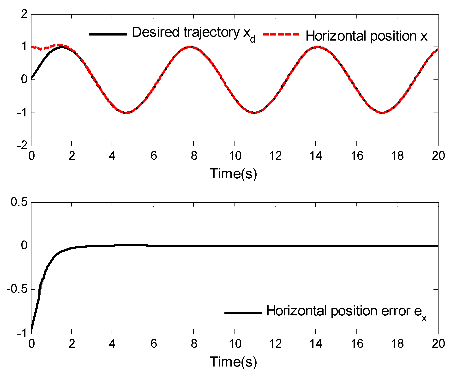
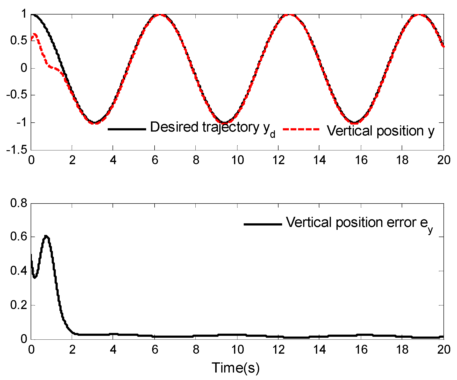
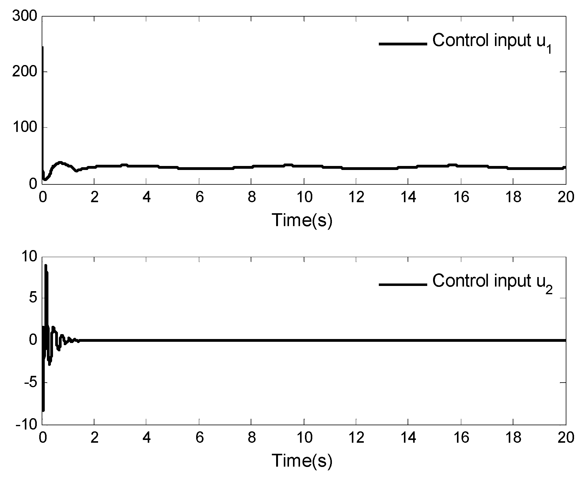
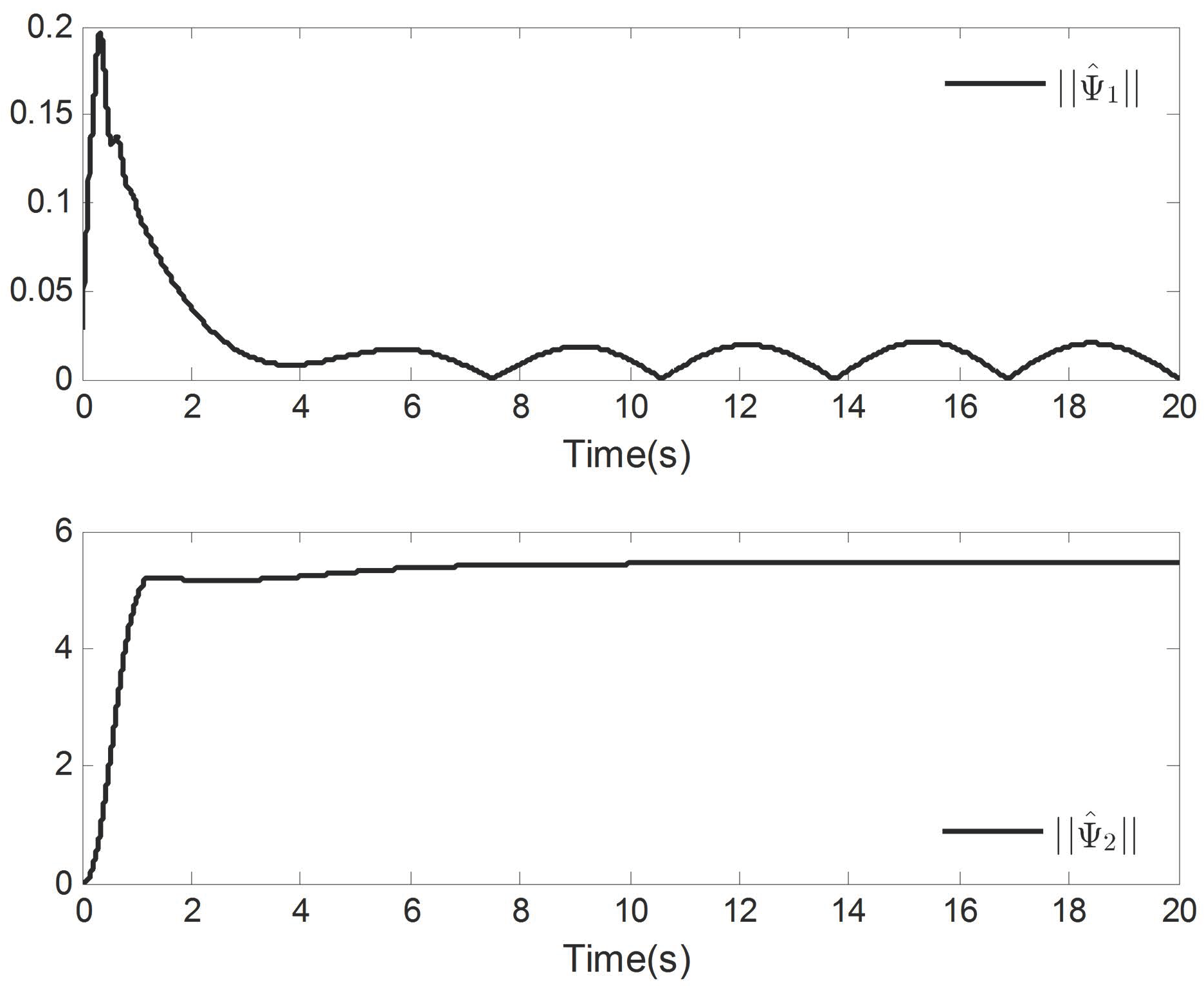
The simulation results as displayed in Figure 3, Figure 4, Figure 5, Figure 6, Figure 7 and Figure 8.
Figure 3, Figure 4 and Figure 5 provide the curves of horizontal position tracking and tracking error, vertical position tracking and tracking error, and roll angle tracking and tracking error, respectively. From these figures, it can be determined that the asymptotic tracking problem of a VTOL aircraft can be well solved by applying the designed neuroadaptive control law. Moreover, the tracking error can converge to a small neighborhood of zero. In other words, although the aircraft system is affected by external disturbances, better tracking performance can be achieved by applying the designed control laws.
Figure 6, Figure 7 and Figure 8 show the curves of the control inputs u 1 and u 2 , the adaptive update laws Ψ ^ 1 , Ψ ^ 2 , Δ ^ 1 , Δ ^ 2 and Δ ^ 3 , respectively. It is not difficult to determine that all signals of the closed-loop system of the VTOL aircraft are bounded. Further investigating Figure 3, Figure 4, Figure 5, Figure 6, Figure 7 and Figure 8, it is easy to see that the signals of the system are bounded, a fact which also indicates the correctness of the theoretical results.
Example 2.
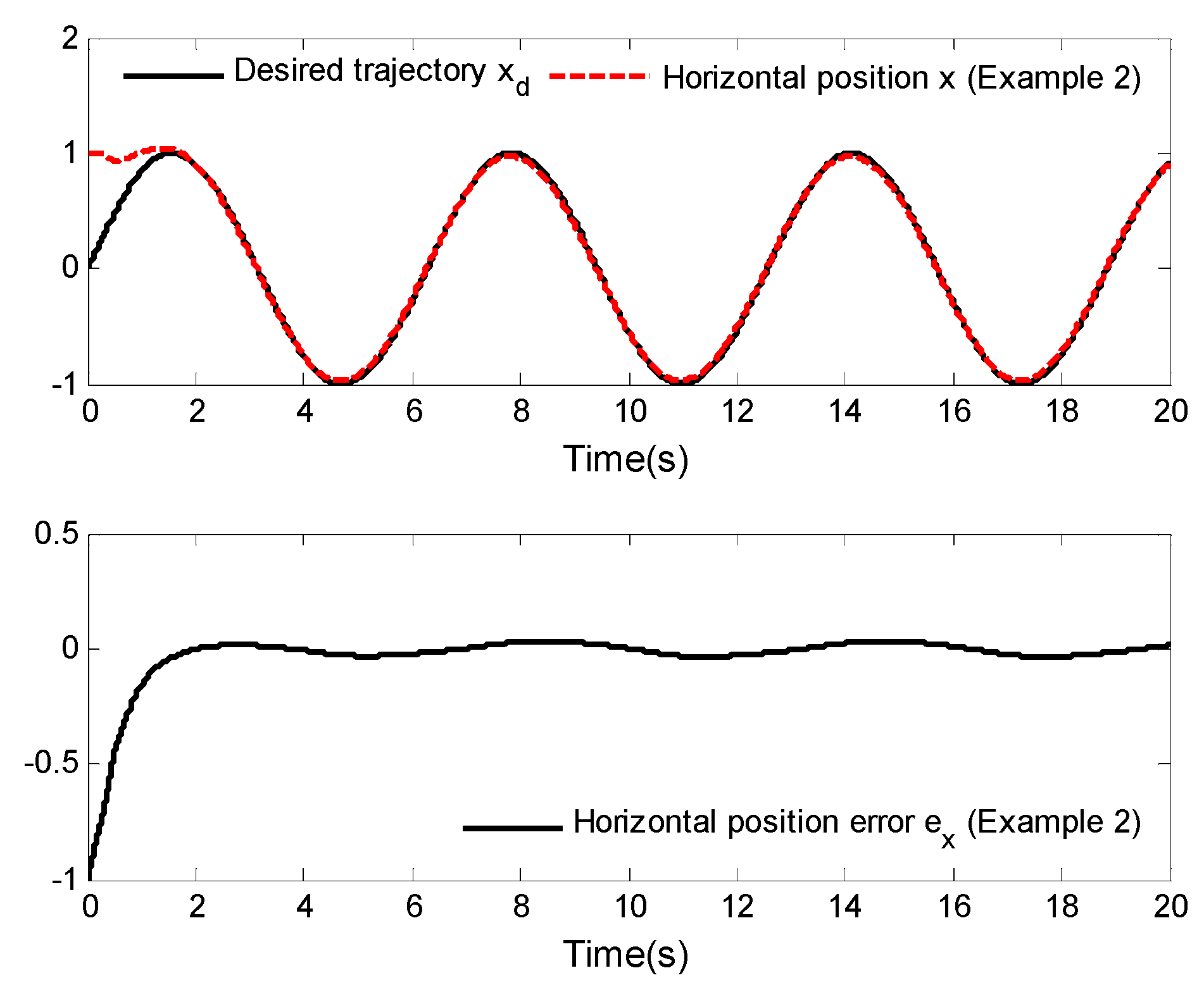
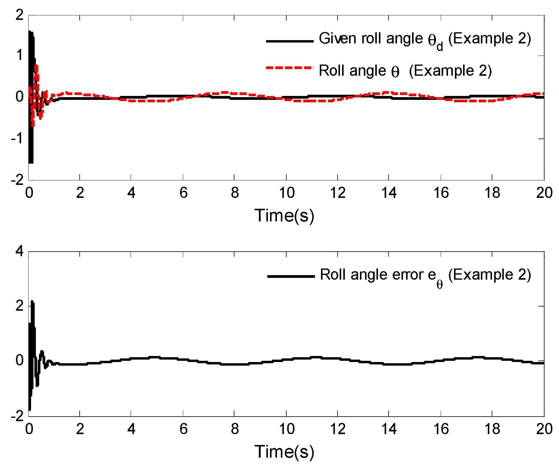
In this example, the external disturbances are given as d 1 ( t ) = d 2 ( t ) = d 3 ( t ) = 0.1 sin ( t ) ; the other parameters are the same as those given in Example 1. The simulation results are shown in Figure 9, Figure 10 and Figure 11.
Figure 9, Figure 10 and Figure 11 display the asymptotic tracking results of horizontal position tracking, vertical position tracking and roll angle tracking, as well as their corresponding tracking error curves. From these figures, it can be observed that the tracking errors become slightly larger compared to Example 1, but that they remain within the small neighborhood of zero. More specifically, although the external disturbances of the aircraft system are ten times larger than those in Example 1, the system can still achieve good tracking performance by applying the control law designed in this paper. This further demonstrates the effectiveness of the designed control law.
Example 3.
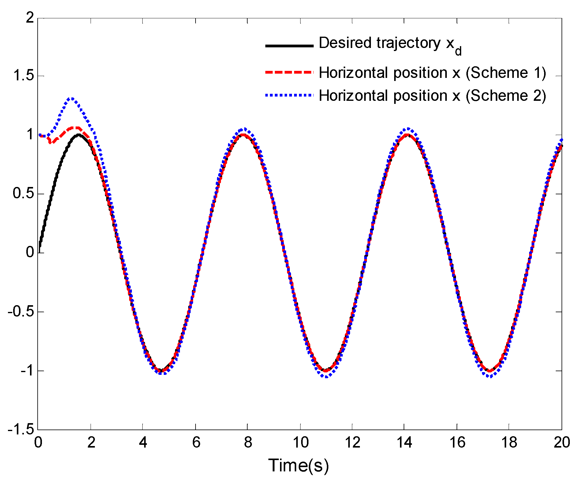
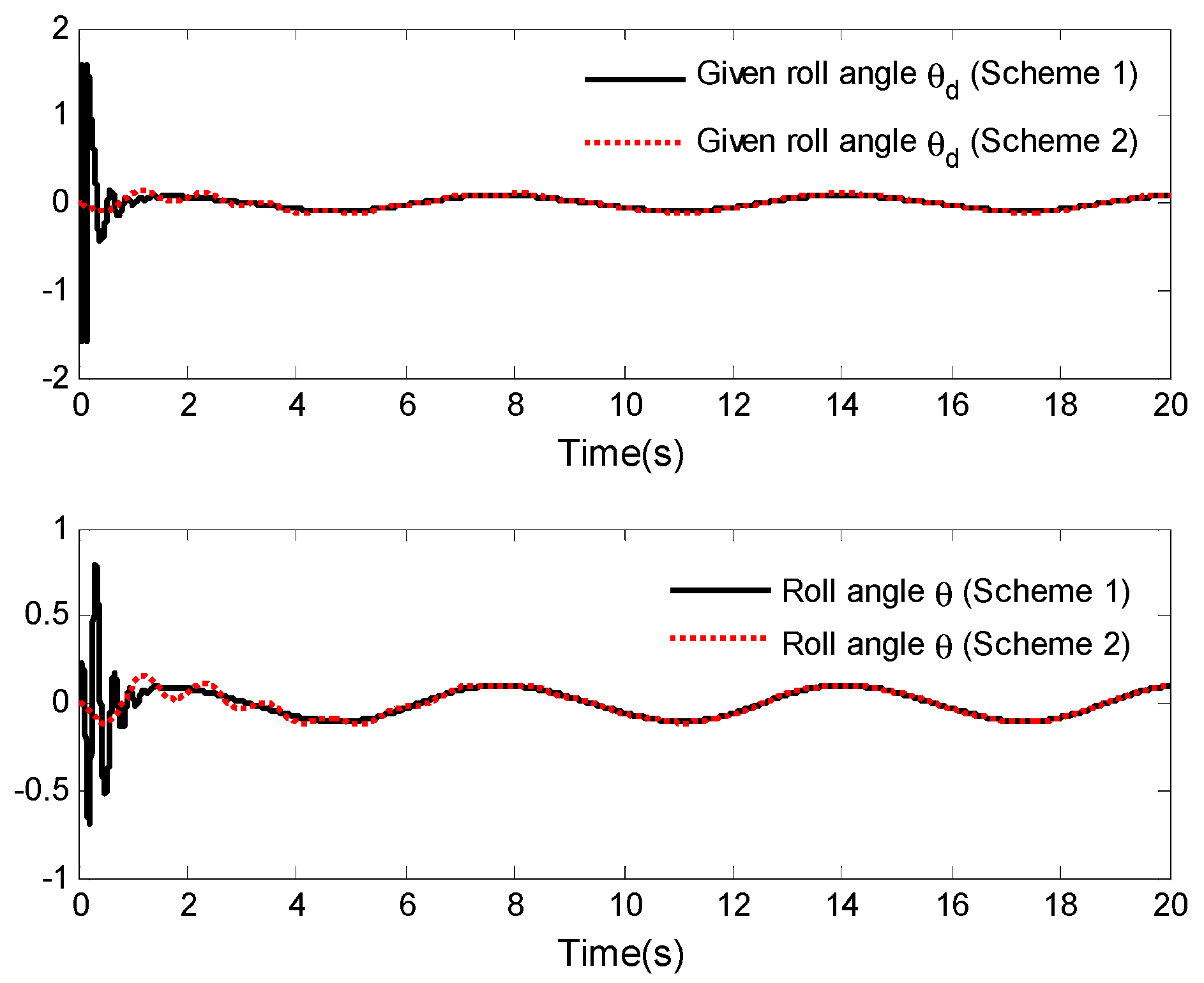
To further describe the validity of the designed control laws, a comparative analysis between the control laws proposed in this work (Scheme 1) and the control laws proposed in [4] (Scheme 2) is undertaken in this example. For the control laws proposed in [4] (Scheme 2), the parameters are set as α 1 = 3.5 , α 2 = 4.3 , β 1 = 1.2 , β 2 = 2.6 , k 1 = κ 2 = 10 , l 1 = l 2 = 9.5 , c = 11 and k = 5.0 . Other parameters are selected as in Example 1. Figure 12, Figure 13 and Figure 14 display the simulation results.
Under Scheme 1 and Scheme 2, the comparison results of the horizontal position tracking performance and vertical position tracking performance are given in Figure 12 and Figure 13. It is easy to see from the two figures that the tracking control of the considered VTOL aircraft is achievable. However, the tracking performance achieved in Scheme 1 is better than that in Scheme 2. The roll angle tracking performance is shown in Figure 14. Although under Scheme 1, the given roll angle and the output roll angle have significant amplitudes in the initial short period of time, they can achieve better control effect and have smaller adjustment time compared to those in Scheme 2. Through this example, the validity of control laws presented in this work is further elucidated.

5. Conclusions

In this work, we investigated the asymptotic tracking control problem of a VTOL aircraft with external disturbances. The dynamic surface control technique and RBF neural network were applied to design neuroadaptive dynamic surface control laws and adaptive update laws. During the recursive design process, first-order filters were introduced in order to avoid repeated differentiation of the designed virtual control laws, and the unknown nonlinear dynamics of the aircraft system were handled by using RBF neural networks. In addition, by using the designed parameter update laws, the approximation errors and external disturbances were effectively dealt with. In addition, by selecting different disturbance types and comparing them with other methods, it is evident that the control laws designed in this work possess better control effects.
We focused on the asymptotic tracking control problem of a VTOL aircraft in this work. We also hope that the VTOL aircraft will be able to achieve the desired target tracking within a predefined time or fixed time under the designed neuroadaptive dynamic surface control laws. Therefore, the predefined time or the fixed time tracking control problem of a VTOL aircraft with neural network dynamic surface control will be studied in our future research.

Author Contributions

Conceptualization, X.Y. and X.D.; Formal Analysis, L.T. and B.X.; Funding Acquisition, X.D., L.T. and B.X.; Investigation, X.D. and L.T.; Methodology, X.Y. and X.D.; Project Administration, L.T. and B.X.; Resources, X.Y. and L.T.; Software, X.Y., X.D. and B.X.; Supervision, L.T. and B.X.; Validation, X.Y.; Visualization, L.T. and B.X.; Writing—original draft, X.Y. and X.D.; Writing—Review and Editing, X.Y., X.D., L.T. and B.X. All authors have read and agreed to the published version of the manuscript.

Funding

This work was partially supported by the National Natural Science Foundation of China under Grant 62203011, the Pre-research Project of National Natural Science Foundation of Anhui Polytechnic University under Grant Xjky2022042, the Open Research Fund of Anhui Key Laboratory of Detection Technology and Energy Saving Devices under Grant DTESD2020B01, the Opening Project of Automotive New Technique of Anhui Province Engineering Technology Research Center under Grant QCKJ202207B, and the Program for the Top Talents of Anhui Polytechnic University.

Institutional Review Board Statement

Not applicable.

Informed Consent Statement

Not applicable.

Data Availability Statement

Not applicable.

Conflicts of Interest

The authors declare no conflict of interest.

References

  1. Chadli, M.; Aouaouda, S.; Karimi, H.; Shi, P. Robust fault tolerant tracking controller design for a VTOL aircraft. J. Frankl. Inst. 2012, 350, 2627–2645. [Google Scholar] [CrossRef]
  2. Hu, J.; Zhang, H. Immersion and invariance based command-filtered adaptive backstepping control of VTOL vehicles. Automatica 2013, 49, 2160–2167. [Google Scholar] [CrossRef]
  3. Zhao, D.; Liu, J. Control of VTOL aircraft with position state constraints using the Barrier Lyapunov Function. Asian J. Control. 2020, 22, 1221–1229. [Google Scholar] [CrossRef]
  4. Ailon, A. Simple Tracking Controllers for Autonomous VTOL Aircraft with Bounded Inputs. IEEE Trans. Autom. Control 2010, 55, 737–743. [Google Scholar] [CrossRef]
  5. Chwa, D. Fuzzy Adaptive Output Feedback Tracking Control of VTOL Aircraft with Uncertain Input Coupling and Input-Dependent Disturbances. IEEE Trans. Fuzzy Syst. 2015, 23, 1505–1518. [Google Scholar] [CrossRef]
  6. Aguilar-Ibanez, C.; Suarez-Castanon, M.S.; Sossa-Azuela, J.H. A backstepping-based procedure with saturation functions to control the PVTOL system. Nonlinear Dyn. 2016, 83, 1247–1257. [Google Scholar] [CrossRef]
  7. Zheng, X.; Yang, X. Improved adaptive NN backstepping control design for a perturbed PVTOL aircraft. Neurocomputing 2020, 410, 51–60. [Google Scholar] [CrossRef]
  8. Wood, R.; Cazzolato, B. An Alternative Nonlinear Control Law for the Global Stabilization of the PVTOL Vehicle. IEEE Trans. Autom. Control 2007, 52, 1282–1287. [Google Scholar] [CrossRef]
  9. Chen, P.; Wu, S.; Hsu, C.; Chang, K. Gain-scheduled control of PVTOL aircraft dynamics with parameter dependent disturbance. J. Frankl. Inst. 2008, 345, 906–925. [Google Scholar]
  10. Guo, B.-Z.; Wu, Z.-H.; Zhou, H.-C. Active Disturbance Rejection Control Approach to Output-Feedback Stabilization of a Class of Uncertain Nonlinear Systems Subject to Stochastic Disturbance. IEEE Trans. Autom. Control. 2016, 61, 1613–1618. [Google Scholar] [CrossRef]
  11. Han, H.; Zhang, J.; Yang, H.; Hou, Y.; Qiao, J. Data-driven robust optimal control for nonlinear system with uncertain disturbances. Inf. Sci. 2023, 621, 248–264. [Google Scholar] [CrossRef]
  12. Song, R.; Lewis, F.L. Robust optimal control for a class of nonlinear systems with unknown disturbances based on disturbance observer and policy iteration. Neurocomputing 2020, 390, 185–195. [Google Scholar] [CrossRef]
  13. Gil, J.; You, S.; Lee, Y.; Kim, W. Nonlinear sliding mode controller using disturbance observer for permanent magnet synchronous motors under disturbance. Expert Syst. Appl. 2023, 214. [Google Scholar] [CrossRef]
  14. Zhao, J.; Tong, S.; Li, Y. Fuzzy adaptive output feedback control for uncertain nonlinear systems with unknown control gain functions and unmodeled dynamics. Inf. Sci. 2021, 558, 140–156. [Google Scholar] [CrossRef]
  15. Zhang, K.; Sun, Z.-Y.; Chen, C.-C.; Meng, Q. Global stabilization via output feedback for a class of uncertainty nonlinear systems with time-varying delay and zero dynamics. ISA Trans. 2023, 132, 235–245. [Google Scholar] [CrossRef]
  16. Cui, R.; Yang, C.; Li, Y.; Sharma, S. Adaptive neural network control of AUVs with control input non-linearities using reinforcement learning. IEEE Trans. Syst. Man Cybern. Syst. 2017, 47, 1019–1029. [Google Scholar] [CrossRef] [Green Version]
  17. Zhao, J.; Yang, C.; Gao, W.; Zhou, L. Reinforcement Learning and Optimal Setpoint Tracking Control of Linear Systems with External Disturbances. IEEE Trans. Ind. Inform. 2022, 18, 7770–7779. [Google Scholar] [CrossRef]
  18. Yin, Q.; Zhang, H.; Mu, Q.; Yang, J.; Ma, Q. Multilayer-neural-network observer with compensator and command-filter-based adaptive backstepping tracking control of switched nonlinear systems. J. Frankl. Inst. 2023, 360, 2976–3000. [Google Scholar] [CrossRef]
  19. Liu, J.; Wang, Q.; Yu, J. Event-triggered adaptive neural network tracking control for uncertain systems with unknown input saturation based on command filters. IEEE Trans. Neural Netw. Learn. Syst. 2022. [Google Scholar] [CrossRef]
  20. Guettal, L.; Chelihi, A.; Ajgou, R.; Touba, M.M. Robust tracking control for quadrotor with un-known nonlinear dynamics using adaptive neural network based fractional-order backstepping control. J. Frankl. Inst. 2022, 359, 7337–7364. [Google Scholar] [CrossRef]
  21. Vijay, M.; Jena, D. Backstepping terminal sliding mode control of robot manipulator using radial basis functional neural networks. Comput. Electr. Eng. 2018, 67, 690–707. [Google Scholar] [CrossRef]
  22. Wu, J.; Chen, X.; Zhao, Q.; Li, J.; Wu, Z.-G. Adaptive Neural Dynamic Surface Control with Prespecified Tracking Accuracy of Uncertain Stochastic Nonstrict-Feedback Systems. IEEE Trans. Cybern. 2022, 52, 3408–3421. [Google Scholar] [CrossRef] [PubMed]
  23. Yang, Y.; Liu, Q.; Yue, D.; Han, Q.-L. Predictor-Based Neural Dynamic Surface Control for Bipartite Tracking of a Class of Nonlinear Multiagent Systems. IEEE Trans. Neural Netw. Learn. Syst. 2022, 33, 1791–1802. [Google Scholar] [CrossRef] [PubMed]
  24. Yoo, S. Neural-Network-Based Adaptive resilient dynamic surface control against unknown deception attacks of un-certain nonlinear time-delay cyberphysical systems. IEEE Trans. Neural Netw. Learn. Syst. 2020, 31, 4341–4353. [Google Scholar] [CrossRef] [PubMed]
  25. Liu, J.; Wang, Q.; Yu, J. Convex optimization-based adaptive fuzzy control for uncertain nonlinear systems with input saturation using command filtered backstepping. IEEE Trans. Fuzzy Syst. 2022, 31, 2086–2091. [Google Scholar] [CrossRef]
  26. Chen, L.; Wang, Q.; Hu, C. Adaptive fuzzy command filtered backstepping control for uncertain pure-feedback systems. ISA Trans. 2022, 129, 204–213. [Google Scholar] [CrossRef]
  27. Hauser, J.; Sastry, S.; Meyer, G. Nonlinear control design for slightly non-minimum phase systems: Application to V/STOL aircraft. Automatica 1992, 28, 665–679. [Google Scholar] [CrossRef]
  28. Deng, X.; Zhang, C.; Ge, Y. Adaptive neural network dynamic surface control of uncertain strict-feedback non-linear systems with unknown control direction and unknown actuator fault. J. Frankl. Inst. 2022, 359, 4054–4073. [Google Scholar] [CrossRef]
  29. Ren, B.; Ge, S.S.; Tee, K.P.; Lee, T.H. Adaptive Neural Control for Output Feedback Nonlinear Systems Using a Barrier Lyapunov Function. IEEE Trans. Neural. Netw. 2010, 21, 1339–1345. [Google Scholar] [CrossRef]
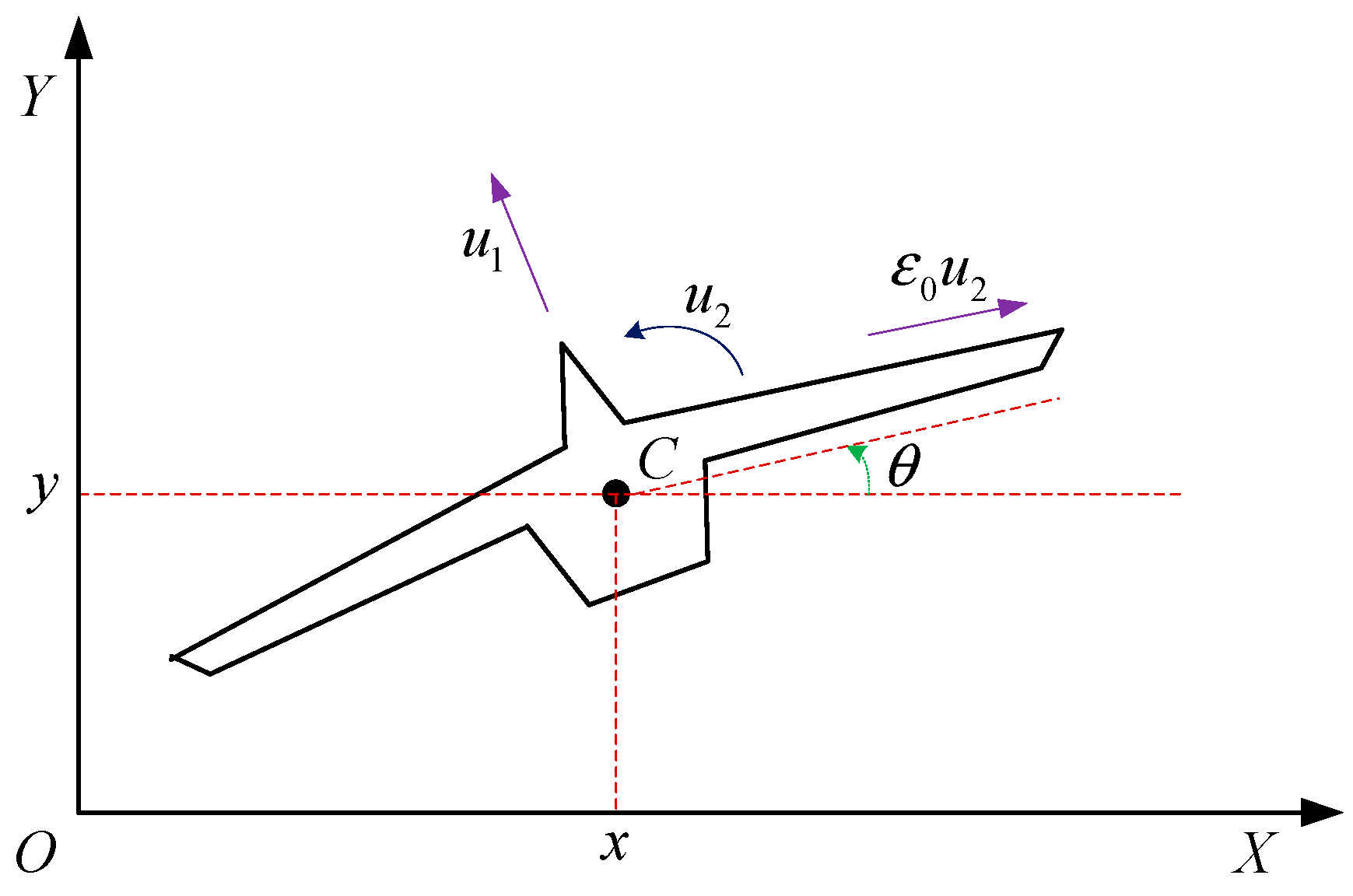
Figure 1. The VTOL aircraft.
Mathematics 11 02725 g001
Figure 2. Control block diagram of VTOL aircraft system.
Mathematics 11 02725 g002
Figure 3. Horizontal position tracking and tracking error.
Mathematics 11 02725 g003
Figure 4. Vertical position tracking and tracking error.
Mathematics 11 02725 g004
Figure 5. Roll angle tracking and tracking error.
Mathematics 11 02725 g005
Figure 6. Control input of VTOL aircraft.
Mathematics 11 02725 g006
Figure 7. Adaptive control laws Ψ ^ 1 and Ψ ^ 2 .
Mathematics 11 02725 g007
Figure 8. Adaptive control laws Δ ^ 1 , Δ ^ 2 and Δ ^ 3 .
Mathematics 11 02725 g008
Figure 9. Horizontal position tracking and tracking error.
Mathematics 11 02725 g009
Figure 10. Vertical position tracking and tracking error.
Mathematics 11 02725 g010
Figure 11. Roll angle tracking and tracking error.
Mathematics 11 02725 g011
Figure 12. Comparison results of horizontal position tracking performance.
Mathematics 11 02725 g012
Figure 13. Comparison results of vertical position tracking performance.
Mathematics 11 02725 g013
Figure 14. Comparison results of roll angle tracking performance.
Mathematics 11 02725 g014
Disclaimer/Publisher’s Note: The statements, opinions and data contained in all publications are solely those of the individual author(s) and contributor(s) and not of MDPI and/or the editor(s). MDPI and/or the editor(s) disclaim responsibility for any injury to people or property resulting from any ideas, methods, instructions or products referred to in the content.