1. Introduction
A new optimization model for the layout problem of a hierarchical orthogonal hypergraph is discussed in this paper. The outputs of the model are node coordinates and hyperedge routing. The number of hyperedge crossings is minimized for better visibility in the graph layout, and some aesthetic metrics are optimized as well [
1,
2].
Every orthogonal hyperedge
e is drawn with a set of upper vertical segments
, a horizontal segment
, and a set of lower vertical segments
. It is assumed in this paper that all hyperedges are directed downwards. Each upper vertical segment of
has the same length and starts in one of the ports of the source node; the number of ports and their coordinates are known for each node. The horizontal segment
is placed on the ordinate of the lower end of the vertical segments of
;
and each vertical segment of
have one conjunction point. The vertical segments of
start on the
segment and arrive at one of the ports of their target nodes.
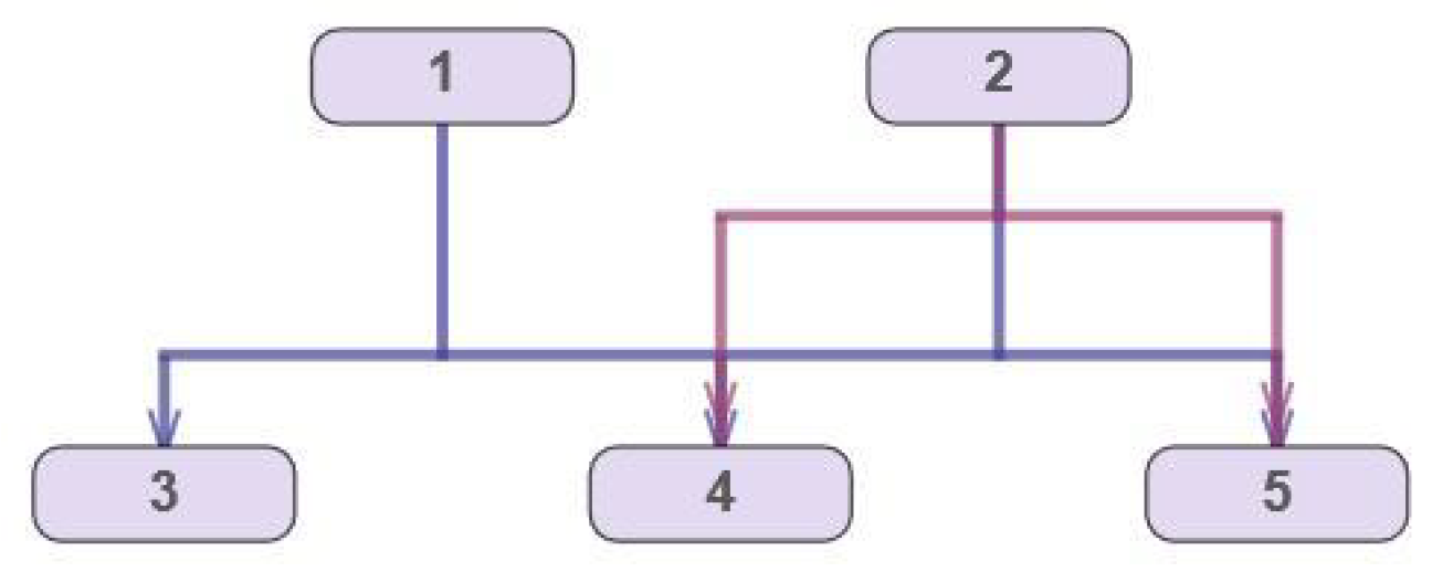
Figure 1 shows an example of the layering of a hierarchical hypergraph with orthogonal hyperedges according to the described rules.
A well-known approach to hyperedge visualization is the replacement of each hyperedge with a set of edges with one dummy node, followed by the use of traditional layout techniques for graphs; then, the hypergraph is restored from the graph layout obtained in the previous step [
3,
4]. Therefore, this problem is closely related to hierarchical (i.e., directed acyclic) graph drawing, and methods based on the Sugiyama approach [
5] will be applied.
To make this algorithm applicable to the hypergraph layout problem, Sander [
6] first proposed reordering the nodes on each layer to minimize the number of edge crossings, and then calculated the preliminary coordinates for the nodes and segments to avoid hyperedge crossings, finally obtaining the coordinates that rendered a balanced drawing. In [
7], an exact formulation of the mathematical problem of hyperedge routing was proposed, and it satisfied the constraints discussed above. The final step of the hypergraph drawing algorithm is assigning each upper vertical segment to a port of its source node and each lower vertical segment to a port of its target node.
Computing the optimal order of vertices for all layers of a graph is a highly time-consuming procedure. That is why it is reasonable to reorder vertices in each layer separately to minimize the number of edge crossings related to one of adjacent layers. A heuristic proposed in [
8] was improved in further work; see [
9].
Plenty of exact and heuristic algorithms have been presented for the minimization of edge crossings by reordering nodes on layers; see, e.g., [
8,
10]. However, application of these methods for a hypergraph might not provide acceptable results. It is known that decreasing the number of edge crossings does not ensure the same for the corresponding hypergraph [
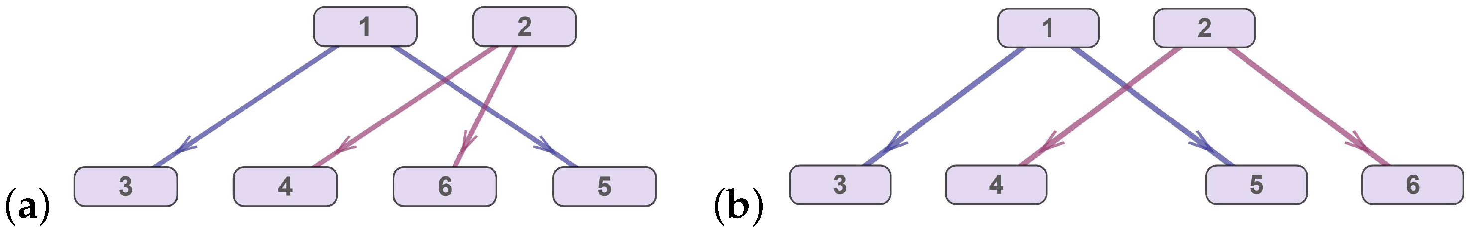
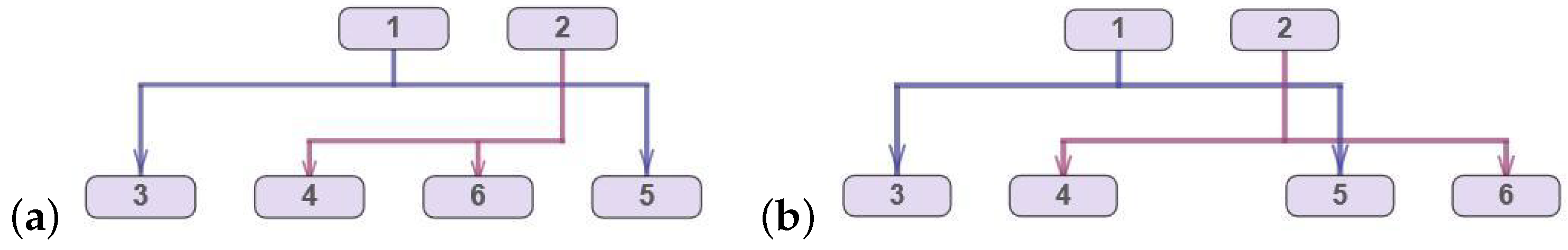
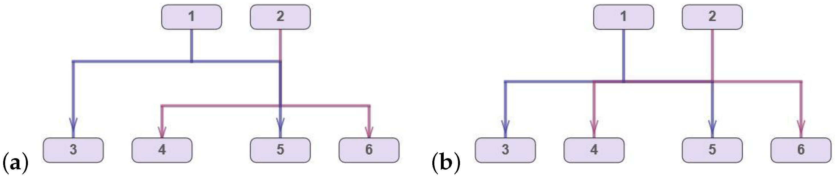
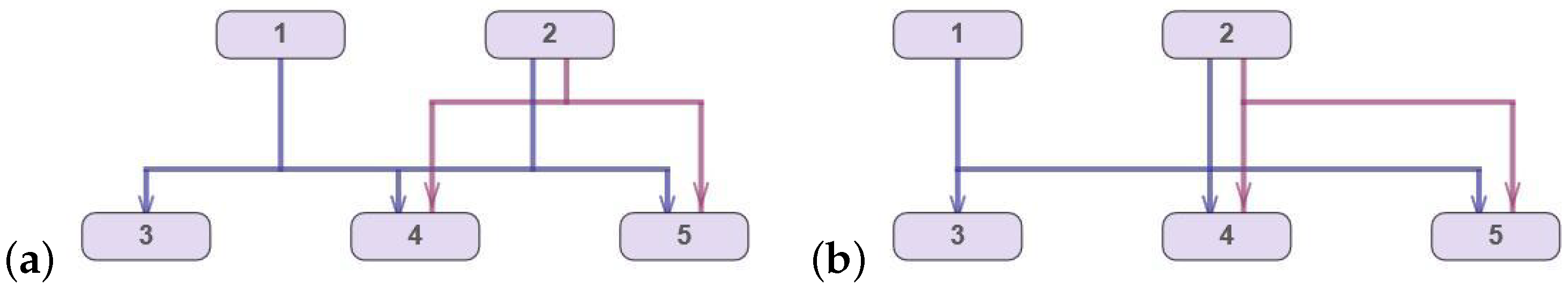
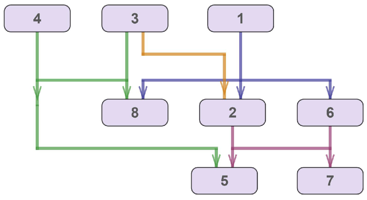
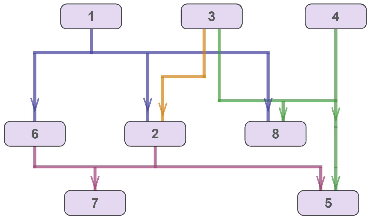
11]; see, for instance,
Figure 2 and
Figure 3, which present examples of single-source one-port hypergraphs.
An additional optimization problem arises if one takes ports for the source and target nodes into account because each vertical segment of a hyperedge must be assigned to a unique port. This problem should be considered as a part of a hierarchical hypergraph drawing problem, together with the reordering of nodes and horizontal segments.
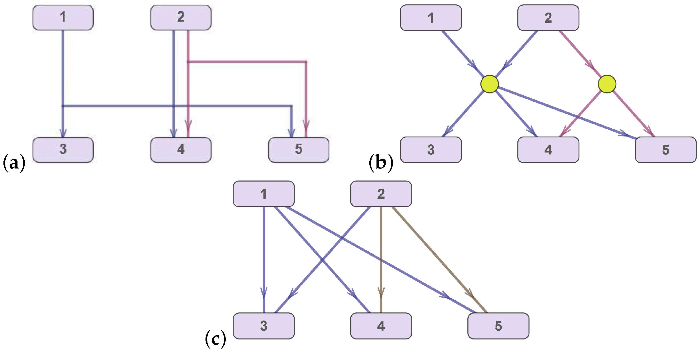
Figure 4 and
Figure 5 show three layouts of the same hypergraph: without ports (optimal layout), with the assignment of ports as a result of a post-processing procedure, and, finally, with the optimal assignment of ports.
The reordering heuristic by Eschbach et al. [
12] only gives a local minimum of the number of hyperedge crossings. Spönemann et al. [
11] proposed an algorithm for quite accurate (but not exact) counting of hyperedge crossings depending on the order of nodes without computing the hyperedge routing.
A hyperedge drawing is applied in a variety of practical areas: from cooperation scheme drawing and information and financial flow visualization to schematics of displays of automotive communication networks and VLSI design. Interesting applications of the hypergraph layout problem can be found in the development of effective routing protocols for IoT applications and in the development of energy-balanced routing protocols for terrestrial/underwater wireless sensor networks, as well as in the assessment of their safety.
The information system for the national investment projects that started in Russia in 2015 is an example of graphical data analysis [
7]. One of the goals of this information system is to control all financial transactions and contracts related to large-scale national projects, in which hundreds of companies are involved. The embedded software visualizes companies as nodes of a hierarchical hypergraph and their business links and financial transactions as directed hyperedges. This visualization scheme enables one to highlight potential risks and to estimate the status of a project under consideration. It is clear that this visualization is only helpful as an analytical tool if it is easy to understand. It is more to the point that the hypergraph density is high.
The neighboring area of application is financial flow visualization for corporations with large numbers of branch offices and commercial subsidiaries. The display of the flow of information within or between universities can be discussed as an application as well.
There are some novel approaches to nanostructures and material science with application of graph theory [
13,
14], where there is a large variety of applications connected with hierarchical hypergraphs with orthogonal hyperedges.
3. Mathematical Model for Drawing a Hierarchical Hypergraph with Orthogonal Hyperedges and Ports
If hypergraph H contains hyperedges connecting the vertices of non-adjacent layers, then every such “long” hyperedge e has to be transformed into several hyperedges that connect the vertices of adjacent layers only, with additional (dummy) vertices being introduced for every e in the following way:
Find adjacent vertices u and v such that ;
Insert a single dummy node on each layer l of hypergraph H, ;
Replace the long hyperedge e with hyperedges that connect the inserted dummy vertices with the incident vertices of the original long hyperedge e so that each new hyperedge connects the vertices of the adjacent layers. This step should hold all of the connections between nodes on adjacent layers that are defined by hyperedge e.
Consider the hypergraph
, which is constructed from the hypergraph
H (after inserting dummy vertices into it) by splitting each vertex into subsets of port vertices. For each vertex
(so-called “generating vertex”), sets
and
of the port vertices are introduced,
and
, where
and
denote the numbers of ports of vertex
u for the upper vertical segments and for the lower vertical segments of the incident hyperedges, respectively. Each port vertex in the set
is considered a vertex of hypergraph
. A function
C is introduced as well. For each port vertex, the function
C yields its generating vertex. Note that
.
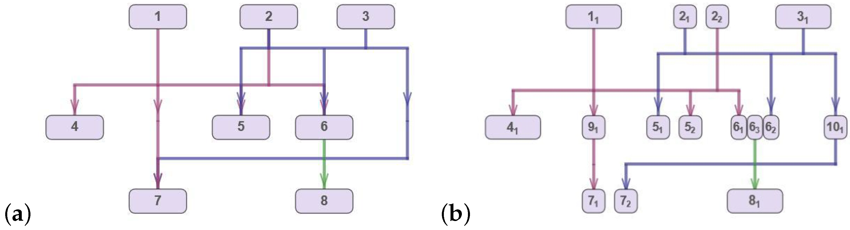
Figure 7 demonstrates an example of such a transformation of hypergraph
H into hypergraph
.
The following specific constraints are to be taken into account for the drawing of hypergraph : port vertices with the same value for function C (those generated by one generating vertex) should be neighboring ones, i.e., between any two port vertices with the same value for function C, on every layer, there is no port vertex with another value for function C.
For the mathematical formulation of the hypergraph drawing problem, three sets of real variables are introduced—X, , and —as well as four sets of integer variables—, , , and .
Variable denotes the x-coordinate of the vertex . The variables and are the x-coordinates of the leftmost and rightmost nodes of hyperedge e, respectively.
A minimum distance is known for each pair of port vertices : (or ), , or each pair of generating vertices : . The order relation for a pair of vertices u and v means that they are in lexicographic order on the same layer.
A maximum distance is known between each pair of port vertices (or ) of a generating vertex u, .
A minimum distance is known between vertical segments and or and for each pair of hyperedges : . The order relation for a pair of hyperedges and means that they are in lexicographic order, and their source vertices are on the same layer.
Each hyperedge has a so-called “area of crossings”. This can be defined as a set of points with coordinates
such that
and
y is between the ordinates of the source and target nodes.
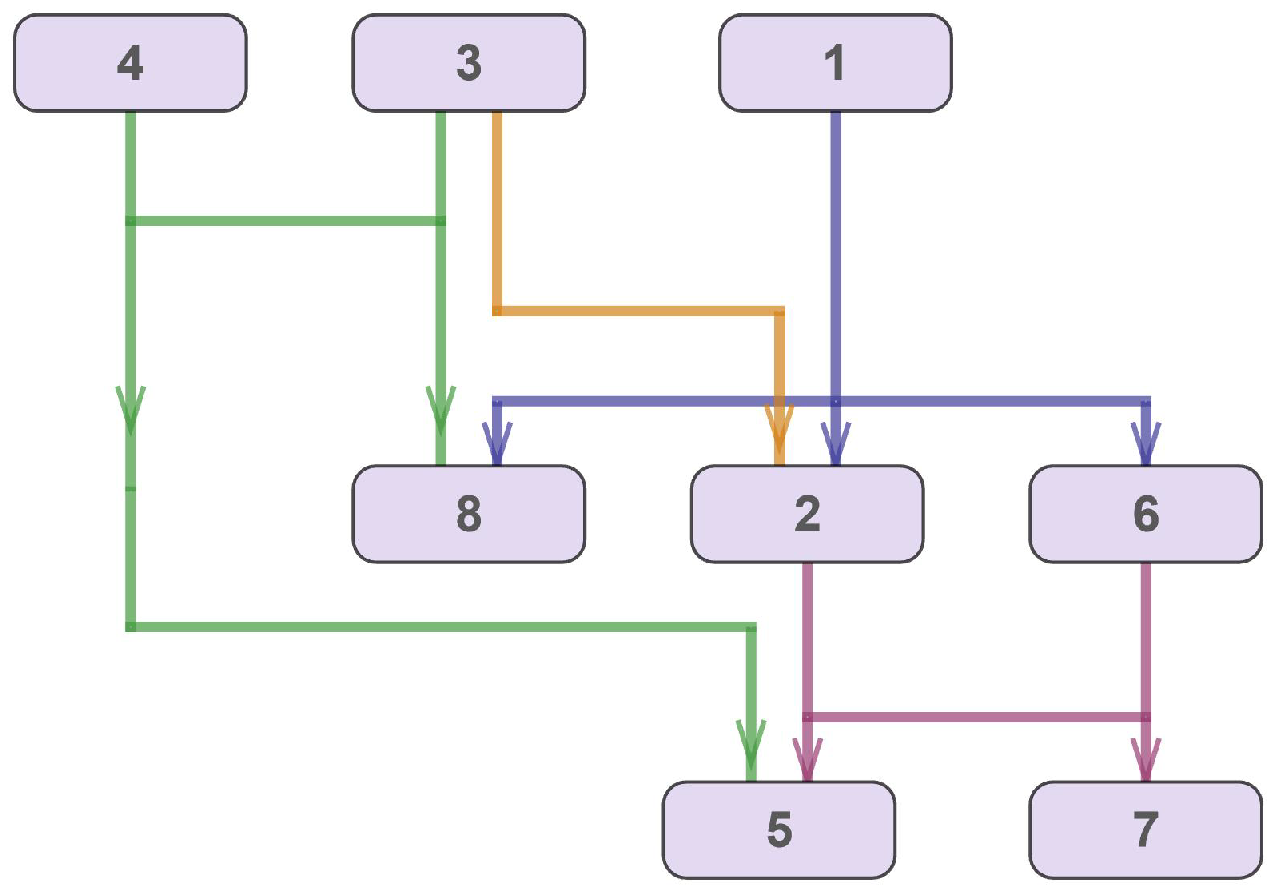
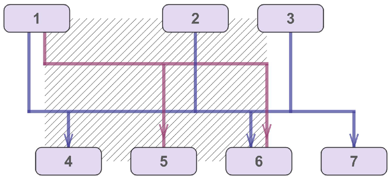
Figure 8 demonstrates the area of crossings of hyperedge
with the incident vertices
. Vertices
, which are incident to another hyperedge
, are inside this region, and vertices 3 and 6 are outside of it.
For each pair of hyperedges
with source vertices on the same layers, where
,
and
, the integer variables
and
and dummy variables
and
are introduced as follows:
The variable is the number of crossings between the horizontal segment of one hyperedge of a corresponding pair of hyperedges and the upper segments of the other hyperedge. Similarly, the variable is the number of crossings between the horizontal segment of one hyperedge of this pair and the lower segments of the other hyperedge. The number of crossings for a pair of hyperedges and depends on the number of port vertices inside the area of crossings of these hyperedges and the relative vertical positions of their horizontal segments.
The following optimization criteria are applied in the model:
These can be formulated in the form:
Note that, in all of the formulae below, denotes the set cardinality for sets and an absolute value for numerical expressions.
The following set of constraints (
7)–(
10) is imposed for the generating and port vertices.
To ensure that no vertices overlap in the hypergraph layout, the distance between every pair of generating vertices
u and
v on the same layer (
) should be equal to or greater than
, i.e.,
. Taking into account that the abscissa of a generating vertex
u can be calculated as the mean value of its port vertices with
abscissas, we re-write this condition in the form
Analogous conditions are to be imposed for the distance between each pair of port vertices
(or
) of every generating vertex
. Note that they set both the minimum and the maximum distance between
and
as follows:
The next set of conditions ensure that the mean value of the
x-coordinates of the port vertices in the sets
and
are equal such that all of the port vertices in
and
are to be merged back into one generating vertex in the hypergraph drawing:
The obvious condition that every port vertex
u incident to hyperedge
e lies between the leftmost and the rightmost vertices incident to hyperedge
e defines the following connection between variables
,
, and
for every hyperedge
e:
A set of constraints (
11)–(
17) is formulated for each pair of hyperedges
,
with source nodes on the same layer.
If the abscissa of a port vertex
u incident to the hyperedge
belongs to the interval that is defined by the
x-coordinates of the leftmost and the rightmost vertices incident to hyperedge
, then the vertex
u is inside the area of crossings of hyperedge
. In this case, there might be a crossing of a vertical segment of hyperedge
connected with the vertex
u and a horizontal segment of hyperedge
. The fact that a vertex is inside the area of crossings for a pair of hyperedges depends on the abscissa of the vertex and the values of the variables
and
in the following manner:
Note that in expression (
11) and in all of the formulae below,
M is an arbitrary large positive number,
.
The nonlinear conditions (
3) and (
4) are to be linearized in a standard manner as follows:
The vertical segments of every two hyperedges have no common point in the hypergraph layout. Hence, one has to ensure a minimum distance between the horizontal positions of the port vertices connected to these segments. The following conditions ensure the absence of non-feasible overlaps of hyperedge segments:
The transitivity condition is to be satisfied for the positions of the horizontal segments of any triplet of hyperedges:
Finally, we determine the domains for all of the variables in the problem:
The standard linearization procedure for nonlinear expressions (
6)–(
9), (
11), (
16), and (
17) allows one to obtain a multi-objective mixed-integer program (
5)–(
21).
Figure 9 illustrates an example of the optimal layout of a hypergraph that was obtained on the basis of the model discussed above.
Two additional post-processing steps are required for an optimal hypergraph layout: first, all dummy vertices must be rendered as points, and second, all subsets of the port vertices corresponding to a generated vertex must be merged back into one vertex.
5. A Mathematical Heuristic for the Hypergraph Layout
The problem of the hypergraph layout in (
5)–(
21) can be solved using the following five-step mathematical heuristic:
Find the order of the vertices on each layer;
Assign preliminary abscissas to the vertices;
Find the relative order of horizontal segments for orthogonal hyperedges with source nodes on the same layer;
Remove the non-feasible overlapping of vertical segments;
Assign ports to the vertical segments.
Note that the aesthetic criteria used in the heuristic coincide with those in
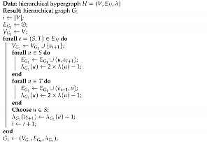
Section 3. The mathematical heuristic is sketched below; see Algorithm 1.
| Algorithm 1: A mathematical heuristic for the hypergraph layout. |
Data: hierarchical hypergraph |
Result: hypergraph drawing D |
; |
; |
; /∗ (26)–(30) ∗/ |
; |
; /∗ (31)–(33) ∗/ |
The first step (vertex ordering) includes a pre-processing procedure for the initial hypergraph
H; the corresponding function is denoted as
in Algorithm 1. A detailed description of this function that returns a graph corresponding to hypergraph
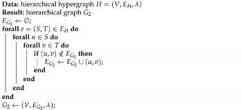
H is given in Algorithm 2.
| Algorithm 2: The function. |
![Mathematics 10 00689 i001]() |
To convert the hypergraph into a graph with the
function, the so-called “balancing vertex” is introduced for each hyperedge
; see
Figure 11a,b. Then, each vertex
incident to the hyperedge is connected by a directed edge to the balancing vertex. This approach enables one to correctly take into account all possible intersections of edges.
The order of the vertices on the layers from
is determined using the
function; see Algorithm 1. The vertex-ordering problem is solved using an integer program [
10] that minimizes the number of edge crossings in a directed acyclic graph.
To assign preliminary abscissas to the vertices (step 2 of the mathematical heuristic), the function
is used. Again, hypergraph
H is pre-processed with the
function; see Algorithm 3. As a result of the transformation, every pair of adjacent vertices on the adjacent layers is connected by a directed edge; see
Figure 11c.
| Algorithm 3: The function. |
![Mathematics 10 00689 i002]() |
Then,
x-coordinates are assigned to the vertices based on the solution to a linear programming problem with objective function (
6); see [
9]. Note that the relative vertex order on each layer remains.
Once step 2 is over, three introduced functions—, remove-Overlapping, and —are applied to obtain the hypergraph drawing. These functions correspond to steps 3, 4, and 5 of the mathematical heuristic, and their detailed description is presented below.
Knowing the
x-coordinates of the vertices, the order of the horizontal segments of the hyperedges is determined. The objective function
L that is minimized in step 3 is the number of hyperedge crossings:
For each pair of hyperedges
and
, one can calculate the number of source nodes
and target nodes
that are inside the area of crossings of hyperedge
. We denote these numbers as
and
, respectively. Then, the system of constraints for the integer programming problem with objective function (
26) is as follows:
Constraints (
27) and (
28) are a simplified version of conditions (
12)–(
15) from the optimization model described in
Section 3. The simplification is based on the fact that the
x-coordinates of vertices are known. Expression (
29) coincides with condition (
18) and ensures that the transitivity condition is satisfied for the positions of the horizontal segments of any triplet of hyperedges. Condition (
30) determines the domains of all of the variables in the problem.
The function
—see Algorithm 1—is the solution to the mixed-integer program in (
26)–(
30). It returns the relative order of horizontal segments of the hyperedges.
In step 4, all non-feasible overlaps of vertical segments of hyperedges are removed by using the integer program proposed in [
7]. This solution is denoted as the
removeOverlapping function in Algorithm 1. Non-feasible overlaps must be eliminated by shifting the vertices on layers by a certain integer number of “single shifts” for each corresponding vertex
x-coordinate while maintaining the relative order of the vertices on the layers. The objective function of the integer programming problem minimizes the total number of shifts of vertices, and the constraints are (
7)–(
21) with fixed values of the
variables for every pair of hyperedges.
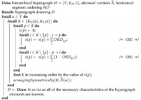
The last step of the mathematical heuristic is the port assignment procedure when the relative order of ports is determined by the
function for each hypergraph vertex—see Algorithm 4—where the
function determines the
x-coordinates of the port vertices by placing them symmetrically to the
x-coordinate of the generating vertex without breaking the relative order of the port vertices.
| Algorithm 4: The function. |
![Mathematics 10 00689 i003]() |
For every generating vertex
u, binary variables
are introduced for each pair of port vertices
or
(relation
holds) as follows:
A numerical parameter
is defined for each pair consisting of a hyperedge
and a generating vertex
:
Consider a pair of a hyperedge
and a generating vertex
. If
, then
u is the leftmost vertex in a set of vertices incident to
e, and if
, then
u is the rightmost one. The equality
means that vertex
u is between the leftmost and the rightmost vertices incident to
e. Parameter
enables one to define the value of
, i.e., the relative order of two port vertices
u and
v, as follows:
where
denotes the unit step function,
u and
v are incident to the hyperedges
and
, respectively,
or
,
, and a numerical parameter
takes the value 2 if port vertex
u for the upper vertical segment of
or 1 in the other case.
Once the relative order of all pairs of port vertices
,
is known, all of the port vertices of the generating vertex
u are positioned so that their mean
x-coordinate coincides with that of the center of
u. The minimal and maximal distances
and
(see
Section 3) should be taken into account.
Figure 12 illustrates a hypergraph layout that was obtained using the mathematical heuristic approach described above.


