Article

Numerical Study of Natural Convection of Power Law Fluid in a Square Cavity Fitted with a Uniformly Heated T-Fin

1
Department of Mathematics, AIR University, AIR Complex, Islamabad 44000, Pakistan
2
Department of Automation, Biomechanics and Mechatronics, Lodz University of Technology, 1/15 Stefanowski St., 90-924 Lodz, Poland
3
Department of Mathematics, Art and Science Faculty, Siirt University, Siirt 56100, Turkey
4
Department of Mathematics, University of Management and Technology, Lahore 54770, Pakistan
*
Author to whom correspondence should be addressed.
Mathematics 2022, 10(3), 342; https://doi.org/10.3390/math10030342
Submission received: 22 September 2021 / Revised: 4 December 2021 / Accepted: 16 December 2021 / Published: 24 January 2022
(This article belongs to the Special Issue Computational Fluid Dynamics II)

Abstract

:
Flow of a liquid in an enclosure with heat transfer has drawn special focus of researchers due to the abundant thermal engineering applications. So, the aim of present communication is to explore thermal characteristics of natural convective power-law liquid flow in a square enclosure rooted with a T-shaped fin. The formulation of the problem is executed in the form of partial differential expressions by incorporating the rheological relation of the power-law fluid. The lower wall of the enclosure along with the fin is uniformly heated and vertical walls are prescribed with cold temperature. For effective heat transfer within the cavity the upper boundary is considered thermally insulated. A finite element based commercial software known as COMSOL is used for simulations and discretization of differential equations and is executed incorporating a weak formulation. Domain discretization is performed by dividing it into triangular and rectangular elements at different refinement levels. A grid independence test is accomplished for quantities of engineering interest like local and average Nusselt numbers to attain accuracy and validity in results. Variation in the momentum and thermal distributions against pertinent parameters is analyzed through stream lines and isothermal contour plots. Measurement of the heat flux coefficient along with the calculation of kinetic energy against involved parameters is displayed through graphs and tables. After the comprehensive overview of attained results it is deduced that kinetic energy elevates against the upsurging magnitude of the Rayleigh number, whereas contrary behavior is encapsulated versus power-law index n . Elevation in the Nusselt number for the shear thinning case i . e . ,   n = 0.5 adheres as compared to Newtonian i . e . ,   n = 1   and shear thickening cases   i . e . ,   n = 1.5 . It is perceived that by the upsurging power-law index viscosity augmentations and circulation zones increases. Heat is transferred quickly against Rayleigh number (Ra) due to production of temperature difference in flow domain.

1. Introduction

The heat transfer phenomenon has always been regarded as an important challenge in engineering and its various mechanisms have been studied accordingly. The procedures are based on heat exchange mechanisms such as electronic cooling, solar collectors, heat exchangers, pollution removal and solar systems. In view of the mentioned practical essence of heat transfer processes researchers are focusing on optimization of the heat transfer process. Like, Eckert and Carlson [1] examined convective flow of air enclosed between two isothermal vertical plates and determined that convection generates fluctuations and wave motion within the flow domain. In addition, they determined that natural convection is dependent on Grashof number. A two-dimensional free convective isothermal flow of air enclosed in a horizontal cavity by prescribing temperature flux conditions at the wall was investigated computationally by Newel and Schdmit [2]. Bonnett and Mclntire [3] tested flow stability in the convective flow of the power law and Ellis models by employing the computational technique. They calculated the critical magnitude of Rayleigh numbers for which free convection converts to forced convection. Tamotusu et al. [4] presented analytical study on 2D laminar natural convection in a cavity filled with viscous liquid by providing heat at the base wall. Flack et al. [5] experimentally measured laminar convection in air flow in a triangular enclosure by providing heat at two side walls and considering the adiabatic bottom wall. Davis [6] computationally investigated the 2D natural convection phenomenon in a square enclosure with differentially heated boundaries. Hasnaoui et al. [7] discussed the convective heat transfer in a cavity by fixing the localized heater at the bottom wall for provision of uniform heat distribution and computed multiple steady state solutions elucidating oscillatory behavior against involved variables. To raise the interest of readers, some of the latest studies on heat transfer are recommended and gathered in references [8,9,10].
Consideration of a fin for the purpose of controlled heat energy propagation in an enclosure is highly recommendable and is a proven strategy. A few decades back, before the advancement in the constructal design industry, different types of cylinder were utilized for appropriate transfer of heat within the flow domain. Nowadays, the requirement of energy in industrial frameworks is fulfilled with the installation of the structured fin. Applications of fin are found in conventional furnaces, economizers, gas turbines, heat exchangers, super conductive heaters, among many other things [11,12,13]. Optimization in convection process in complex geometries with placement of fins was comprehensively explained by Lorenzini et al. [14]. Abdi et al. [15] utilized vertical fins for enhancement in heat flux and energy density in a thermal energy storage framework. Bendaraa et al. [16] explicated advancement in convection in a square enclosure with the placement of conducting fins positioned at different locations. Shi and Khodad [17] evaluated heat transfer attributes of viscous liquid with the placement of a permeable fin fixed on the hot wall. Horbach et al. [18] adumbrated thermal aspects of viscous fluid embedded in a square enclosure by installing the Y-shaped fin and utilized the principle of optimal distribution to minimize maximal excess of temperature for hot spot removal in the whole domain. Rehman et al. [19] investigated buoyantly driven flow of Casson liquid filled in a rhombus shaped chamber fitted with a T-shaped fin. Tavana et al. [20] demonstrated a comparative analysis by computing heat transfer rate of fluid flow containing T and triangular shaped fins and demarcated that the triangular fin is more influential in transferring energy than the T-shaped fin. Insertion of cold fins to control convective heat diffusion in a partially heated enclosure was depicted by Scozia and Frederick [21]. Facas et al. [22] scrutinized the influence of fin length variation on thermal aspects of liquid bounded by a differentially heated square enclosure. Bahiraei et al. [23] implemented a numerical approach to analyze the impression of different fins on convective single-phase nano liquid flow in a micro channel. Li et al. [24] probed the potential aspect of change in the length of rectangular parallel fins on thermal performance of nano particles suspended in base fluid.
Materials depending on viscosity respond differently to the application of stresses. The difference in behavior of liquid characterizes them into Newtonian and non-Newtonian liquids. The liquids whose strains remain linear against stress factors are known as Newtonian fluids, whereas fluids showing non-linear attributes are known as non-Newtonian fluids. Admirable applications of non-Newtonian liquids are accounted in oil-pipeline friction, surfactant, cooling systems, flow traces, the mining industry, slurries, lubrication and biomedical flows. For comprehensive examination of non-Newtonian liquids they are characterized into two main classes, namely, the shear thinning and thickening liquids. This classification has raised the essence of non-Newtonian fluids in multiple advanced processes like food formation, oil refining, heating and cooling systems and nuclear power plant, polymerization, friction reduction, flow traces and so forth. In this regard, the rheological experts have proposed various models to represent the classification. Among these propositions, there are various fluid models describing rheological attributes on non-Newtonian models. Among these models the most generic one describing the features comprehensively is the power-law fluid. Ozoe and Churchill [25] analyzed convection in power law fluid flow in horizontal cavity by measuring hydrodynamic stability and circulating zones against model parameters. Kaddiry et al. [26] calculated the range of the power-law index for which the fluid model depicts flow characteristics of shear thinning and thickening materials by considering flow in a square enclosure. Kim et al. [27] deliberated the buoyantly convective transient flow of the power-law liquid in an isothermal square enclosure, prescribing different temperature at boundaries. Some recent developments on non-viscous fluid flow in different domains are encapsulated in references [28,29,30].
Natural convection is an abundant phenomenon generated by density differences which may arise in many settings like air craft surfaces, melt spinning, drying and coating technologies, computers chips, solar paneling, wind chiller, hydraulic pumps, molten metals, heat dissipation fins, hydrothermal reservoirs, filtration processes, nuclear waste storing, solidification of castings, liquefaction gases and biofilm growth. In view of their superb practical utility, researchers have conducted studies. Like, Turan et al. [31] illuminated natural convection generated by the provision of differentially heated side walls of an enclosure filled completely with a non-Newtonian fluid obeying the power-law model. Ternik and Rudolf [32] simulated results for hydrodynamic and thermal fields for the power-law rheological model coupled with Boussinesq approximation by incorporating the finite volume method. Sajoudi et al. [33] performed delineated convection in a trapezoidal enclosure saturated with quiescent power-law liquid by keeping top and bottom surfaces adiabatic. Turan et al. [34] manipulated the influence of the aspect ratio of heaters placed on walls of a rectangular enclosure on steady state simulations of laminar natural convective flow. Ternik and Buchmiester [35] revealed the buoyantly induced flow of the power-law liquid in a square enclosure with Dirichlet heat flux conditions and measured variation in heat transfer against the dimensionless Prandtl number. Alloui and Vesseur [36] examined natural convection in a non-Newtonian liquid filled in a vertical enclosure by specifying Neumann type of thermal conditions. Some of the latest work on free convective heat transfer in power-law fluid is encapsulated in references [37,38,39,40,41,42,43,44,45].
From the aforementioned literature it is easy to conclude that flow and heat transfer characteristics of non-Newtonian power-law fluid in the presence of T-shaped fin have not yet been considered. This work is an extension of the study conducted by Roy et al. [30] in which they performed natural convection in a square enclosure filled with viscous fluid by providing uniform and non-uniform heating. So, this document contains innovative results and shows novelty concerning the investigation of the non-Newtonian model describing features of shear thinning and thickening fluids with the installation of a T-shaped fin. Formulation of the problem expressing the aspects of natural convection is represented in the form of partial differential equations. Then, variables are used for their non-dimensionalization for distinctive physical interpretation. Commercial software based on a finite element method known as COMSOL is used to find the solution. Variation in velocity and temperature against involved physical parameters is displayed through graphs. Quantities of engineering interest like local and average Nusselt numbers, kinetic energy and cutlines are shown through sketches and tables. Credibility of computed results are delineated by performing a grid independence test along with the provision of reference with published work. Agreement of the presently computed results is made by constructing a comparison with results published by Roy et al. [30].

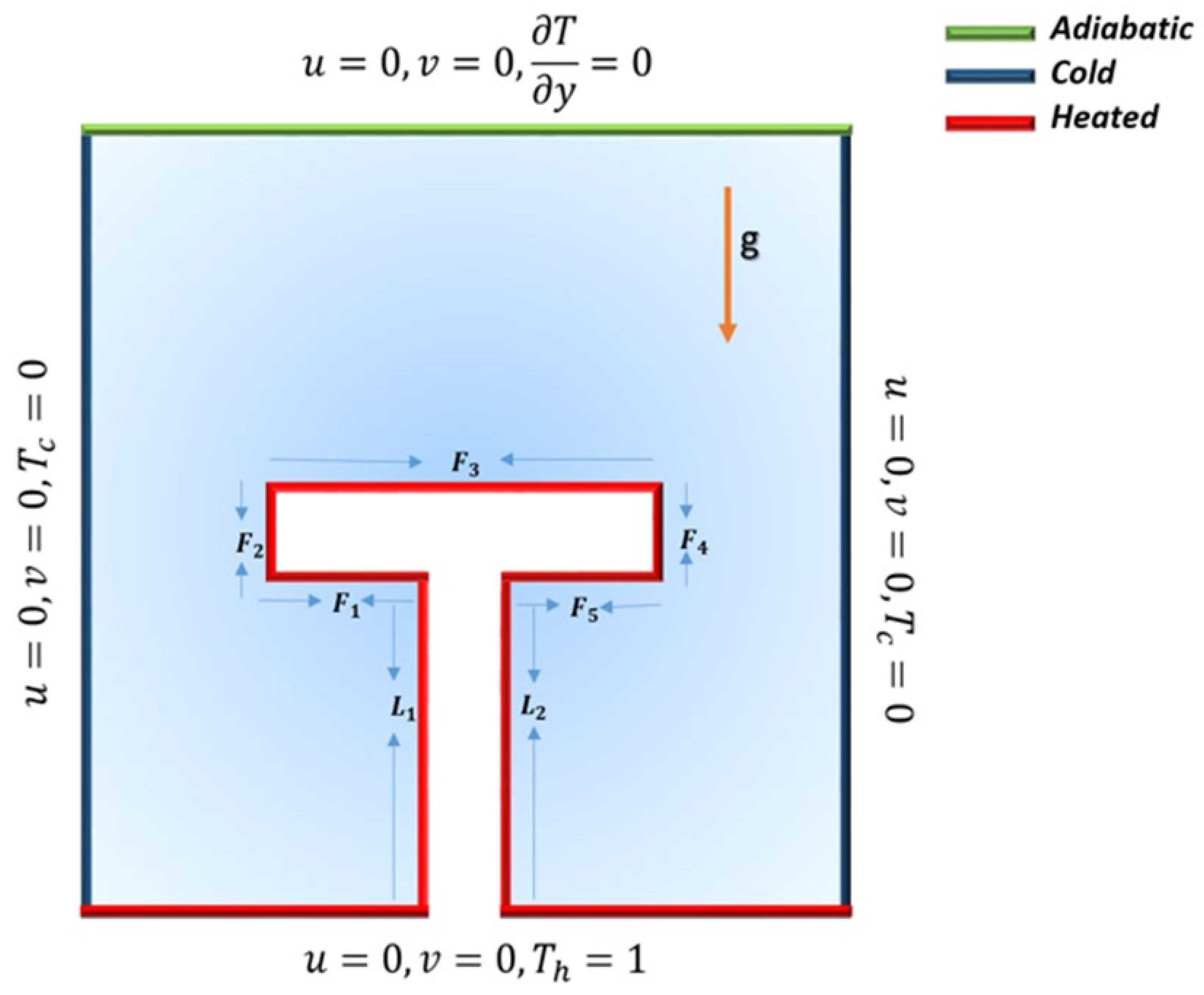
2. Problem Definition and Mathematical Formulation

Assume free convective 2D steady flow of an incompressible power-law fluid embedded with T-shaped fin. The square shape enclosure is taken into consideration and bounded by isothermal vertical walls along with uniformly heated lower wall. The T-shaped fin is rooted at the bottom surface of the enclosure and prescribed with uniform heating at all faces and ribs. The enclosure is considered to be impermeable along with the assumption of no wall motion. The physical configuration of the problem is illustrated in Figure 1.
The governing constitutive equations [36] are as follows
u x + v y = 0 ,
ρ ( u u x + v u y ) = p x + τ x x x + τ x y y ,
ρ ( u v x + v v y ) = p y + τ x y x + τ y y y + ρ g β ( T T c ) ,
u T x + v T y = α 2 T x 2 + 2 T y 2 .
The stress tensor τ i j of a non-Newtonian fluid is stated as
τ i j = 2 μ a D i j = μ a u i x j + u j x i .
where, D i j is the rate of the strain tensor; μ a is the apparent viscosity for 2D Cartesian coordinates.
μ a = K 2 u x 2 + v y 2 + v x + u y 2 n 1 2 .
The associate dimensional boundary conditions are as follows
u ( x , 0 ) = u ( x , L ) = u ( 0 , y ) = u ( L , y ) = 0 , v ( x , 0 ) = v ( x , L ) = v ( 0 , y ) = v ( L , y ) = 0 , T ( x , 0 ) = T h ,   T y ( x , L ) = 0 , T ( 0 , y ) = T ( L , y ) = T c .
Dimensionless quantities are defined as below,
X = x L , Y = y L , U = u L α , V = v L α ,
P = p L 2 ρ α 2 , θ = T T c Δ T , Δ T = q L k .
Dimensionless representation of governing equations is defined as follows
U X + V Y = 0 ,
U U X + V U Y = P X + Pr 2 X μ a * U X + Y μ a * U Y + V X ,
U V X + V V Y = P Y + Pr 2 Y μ a * V Y + X μ a * U Y + V X + R a Pr θ ,
U θ X + V θ Y = 2 θ X 2 + 2 θ Y 2 .
where μ a * is the non-dimensional apparent viscosity defined as,
μ a * = 2 U X 2 + V Y 2 + V X + U Y 2 n 1 2 .
Associated boundary conditions in dimensionless form are as follows,
U ( X , 0 ) = U ( X , 1 ) = U ( 0 , Y ) = U ( 1 , Y ) = 0 , V ( X , 0 ) = V ( X , 1 ) = V ( 0 , Y ) = V ( 1 , Y ) = 0 , T ( X , 0 ) = 1 ,   T y ( X , 1 ) = 0 ,   T ( 0 , Y ) = T ( 1 , Y ) = 0 .
Physical parameters are defined as under
R a = ρ g β Δ T L 2 n + 1 α n K , Pr = K L 2 2 n ρ α 2 n .

3. Numerical Details

Since the attained differential system presented in Equations (10)–(13) along with the associated boundary constraints given in Equation (14) are non-linear in nature, so analytical methods do not provide support for the solution of such complex coupled problems. In this regards, the computational scheme like the finite element method is the most efficient for finding the optimized solution along with the comprehensive physical description of the underlying physics of the problem. For the implementation of the finite element method firstly equations are discretized by incorporating weak formulation, then the underlying discrete non-linear system of equations is solved by the Newton method and the linear inner system in solved with the direct solver PARDISO (Advanced Computing Laboratory, Institute of Computing, Università della Svizzera italiana, Lugano, Switzerland) by accomplishing LU matrix factorization, reducing the number of iterations required for the desired level of convergence. This reduces the number of the iterations required. The Lagrangian system is used for velocity discretization (second order) of elements, whereas for pressure and temperature (linear order) the method is as shown in Figure 2.

3.1. Discretization of Equations

This section is presented to discuss the basis of the finite element procedure, i.e., discretization of modelled governing continuity, momentum and energy couple partial differential equations by constructing a weak formulation. The weak form is a mathematical manipulation to relax strong requirements on a PDE by reducing the continuity condition on basis functions. The weak form allows to capitalize on the lesser degree of polynomials to approximate field variables. In addition, there are two attributes of this finite element method; firstly it is based on the idea of partitioning bounded domain Ω into the I R n number of the small non-overlapping domains over which functions are approximated by test functions lying in the test spaces. Secondly, the systematic representation of the approximation of function spaces by piecewise approximation over subdomains produces the sequence of functions that can be approximated by Sobelev test spaces.
The test spaces for field variables like pressure, velocity and temperature are defined by considering W = H 1 Ω 3 to be the test subspaces for u , v , θ and Q = L 2 Ω to be the test space for pressure.
The weak form of the momentum equation in the x-direction for the whole domain Ω is given as
Ω U U X + V U Y w d Ω + Ω P X w d Ω Pr Ω 2 X μ a * U X + Y μ a * U Y + V X w d Ω = 0
Weak formulation of the momentum equation in the y-direction including natural convection over complete domain Ω is expressed as
Ω U V X + V V Y w d Ω + Ω P Y w d Ω Pr Ω 2 Y μ a * V Y + X μ a * U Y + V X w d Ω R a Pr Ω θ w d Ω = 0 ,
The continuity equation in integral form is defined as below
Ω U X + V Y q d Ω = 0 ,
The heat equation after using the weak formulation is described as
Ω U θ X + V θ Y w d Ω Ω 2 θ X 2 + 2 θ Y 2 w d Ω = 0 ,
μ a * = Ω 2 U X 2 + V Y 2 + V X + U Y 2 n 1 2 w d Ω
All physical phenomena are continuous, but solving a problem by using a computer with a continuous approach is very difficult. So, the basis of numerical methods is to discretize the continuous problem in discrete form for better understanding. The continuous solution fields such as pressure, velocity and temperature are discretized by using finite dimensional subspaces defined as below
U U h W h V V h W h θ θ h W h P P h Q h
Using Equation (22) in Equations (18)–(20), the following discrete version is attained
Discretized form of momentum equation in the x-direction is represented as
Ω U h U h X + V h U h Y w h d Ω + Ω P h X w h d Ω Pr Ω 2 μ a * X U h X + μ a * Y 2 U h Y 2 + 2 V h Y X w h d Ω = 0
Discretized version of the momentum equation in the y-direction is given below
Ω U h V h X + V h V h Y w h d Ω + Ω P h Y w h d Ω Pr Ω 2 μ a * Y 2 V h Y 2 + μ a * X 2 U h X Y + 2 V h X 2 w h d Ω R a Pr Ω θ h w h d Ω = 0 ,
The continuity equation in discretized form is represented as below
Ω U h X + V h Y q h d Ω = 0 ,
The discretized form of the energy equation is described as below
Ω U h θ h X + V h θ h Y w h d Ω Ω 2 θ h X 2 + 2 θ h Y 2 w h d Ω = 0 ,
The viscosity relation for the power-law fluid for each element is defined as below
μ a * = Ω 2 U h X 2 + V h Y 2 + V h X + U h Y 2 n 1 2 w h d Ω
The discrete solution in the form of basis functions of linear functionals is
U h k = 1 ndof U k φ k ( X , Y ) , V h k = 1 ndof V k φ k ( X , Y ) , P h k = 1 ndof P k ψ k ( X , Y ) , θ h k = 1 ndof θ k φ k ( X , Y ) .
where ndof represents the number of degrees of freedom and then Equations (18)–(21) give rise to the momentum equation in the x-direction at the element level for n degrees of freedom
Ω U h U h X + V h U h Y w h d Ω + Ω P h X w h d Ω Pr Ω 2 μ a * X U h X w h X + μ a * Y 2 U h Y 2 2 w h Y 2 + 2 V h Y X 2 w h Y X d Ω = 0
The momentum equation in the y-direction at the element level for n degrees of freedom is
Ω U h V h X + V h V h Y w h d Ω + Ω P h Y w h d Ω Pr Ω 2 μ a * Y 2 V h Y 2 2 w h Y 2 + μ a * X 2 U h X Y 2 w h X Y + V h X 2 w h X 2 d Ω R a Pr Ω θ h w h d Ω = 0 ,
The continuity equation at the element level for n degrees of freedom is
Ω U h X + V h Y q h d Ω = 0 ,
The temperature equation at the element level for n degrees of freedom is
Ω U h θ h X + V h θ h Y w h d Ω + Ω θ h X w h X + θ h Y w h Y d Ω = 0 .
The system of non-linear momentum and energy equations in matrix representation is given as below
Pr . L h + N U h , V h 0 B 1 0 0 Pr . L h + N h U h , V h B 2 R a Pr M h B 1 T B 2 T 0 0 0 0 0 L h + N h U h , V h U ¯ V ¯ P ¯ θ ¯ = F 1 F 2 F 3 F 4 .
which can be written as: A ξ = F
L h : Discrete Laplace matrix; N h : Non-linear convection matrix; M h : Mass matrix; ξ : Solution vector; F : Right-hand side after implementation of boundary condition. To compute the solution, this non-linear system is iterated till a specified convergence criterion is met. The nonlinear iterations are stopped when the residual is dropped by 10 6 .

3.2. Grid Independence Test

Quantities of Engineering Interest

Kinetic energy (K.E.) in the cavity, which is one of the global quantities, is defined mathematically as follows
E = 1 2 Ω u 2   d Ω .
Average Nusselt number N u A v g is computed and formulated by the expression:
N u A v g = 1 s s N u L o c a l d s .
The local Nusselt number N u L o c a l on the surface T shaped fin is estimated by the following expression:
N u L o c a l = θ n s .
where ( s ) and ( n ) are the surfaces of the thermal region and the normal direction to the surface.
Validation of the implemented computational scheme is assured by developing grid independence and is presented in Table 1. The quantities of engineering interest like kinetic energy and local Nusselt number defined in Equations (35)–(36) at different refinement levels are listed in Table 1, fixing R a = 1000 ,   P r = 6.2 and n = 1 . From the attained values of both physical quantities it is observed at the fine level that the values match the magnitude at the finer level. These benchmark results disclose the fact that the results at levels 6 and 7 are in close agreement. In view of this match all the simulations are computed at level 6 to save computational and time cost.

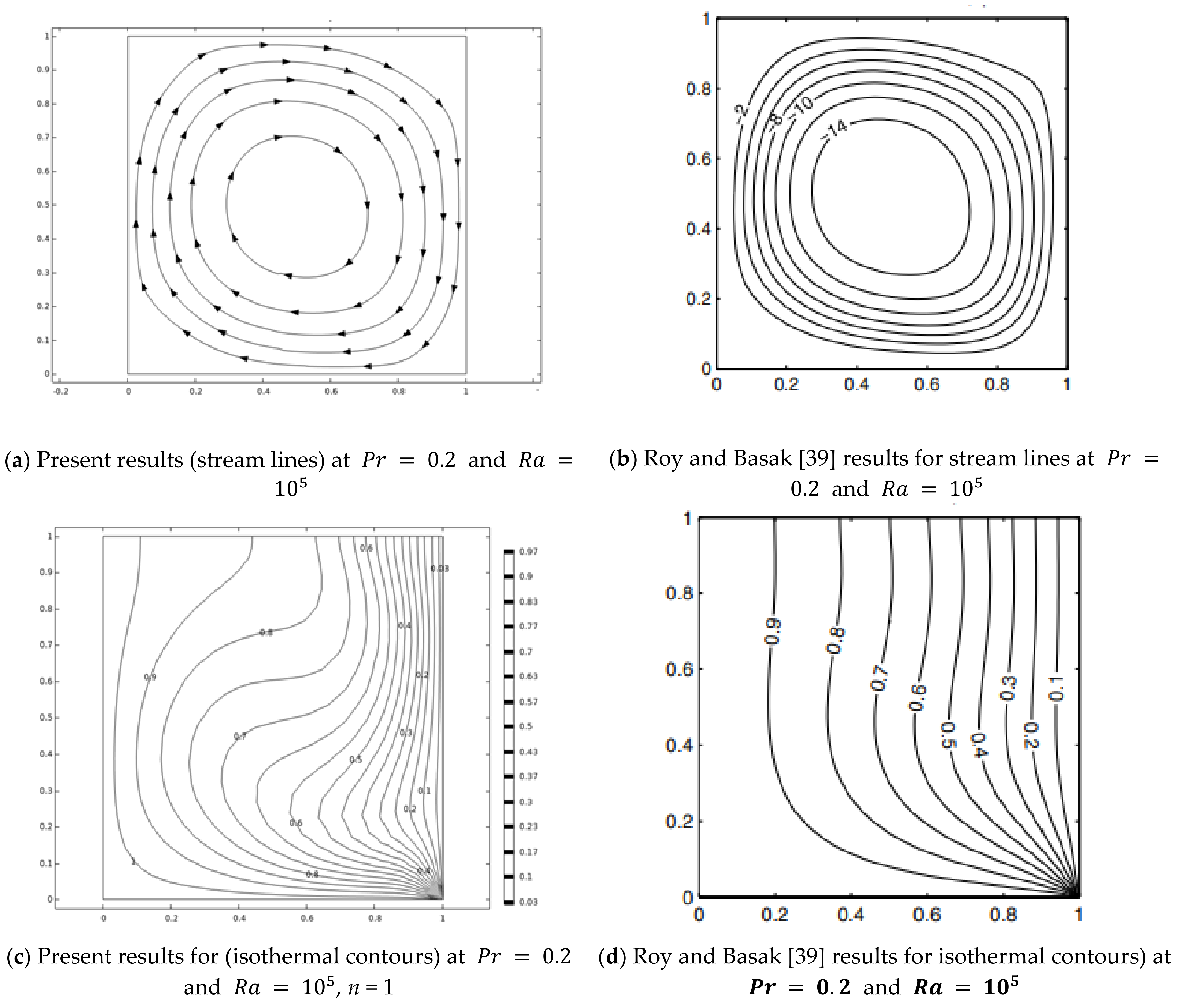
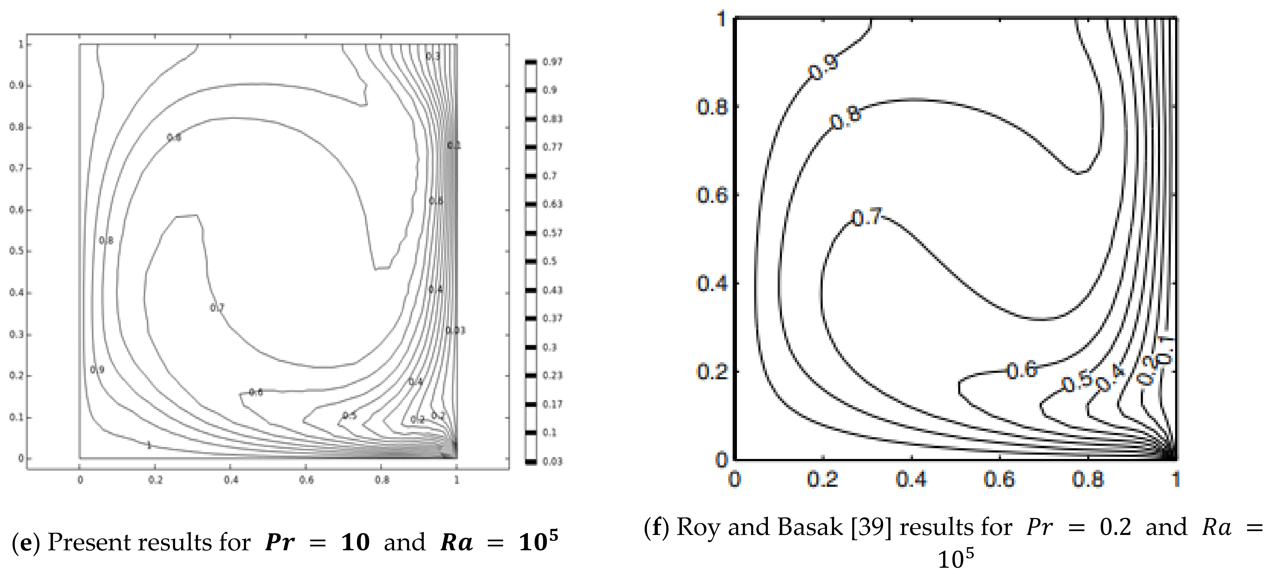
3.3. Result Validation

The credibility of currently conducted computations is assured by comparing with the work published by Roy and Basak [39]. For agreement of the present simulations, restriction of physical parameters is made where n = 1 . Graphical results for velocity stream lines and isothermal contours against Prandtl number P r and Rayleigh number R a are sketched. From graphical structures total agreement is accomplished. In addition, tabular values of average Nusselt number against (n) are compared with previous work published by Khezzar et al. [30] and Sojoudi et al. [33]. From the data it is also depicted that the average Nusselt number magnitudes are in complete agreement with each other.

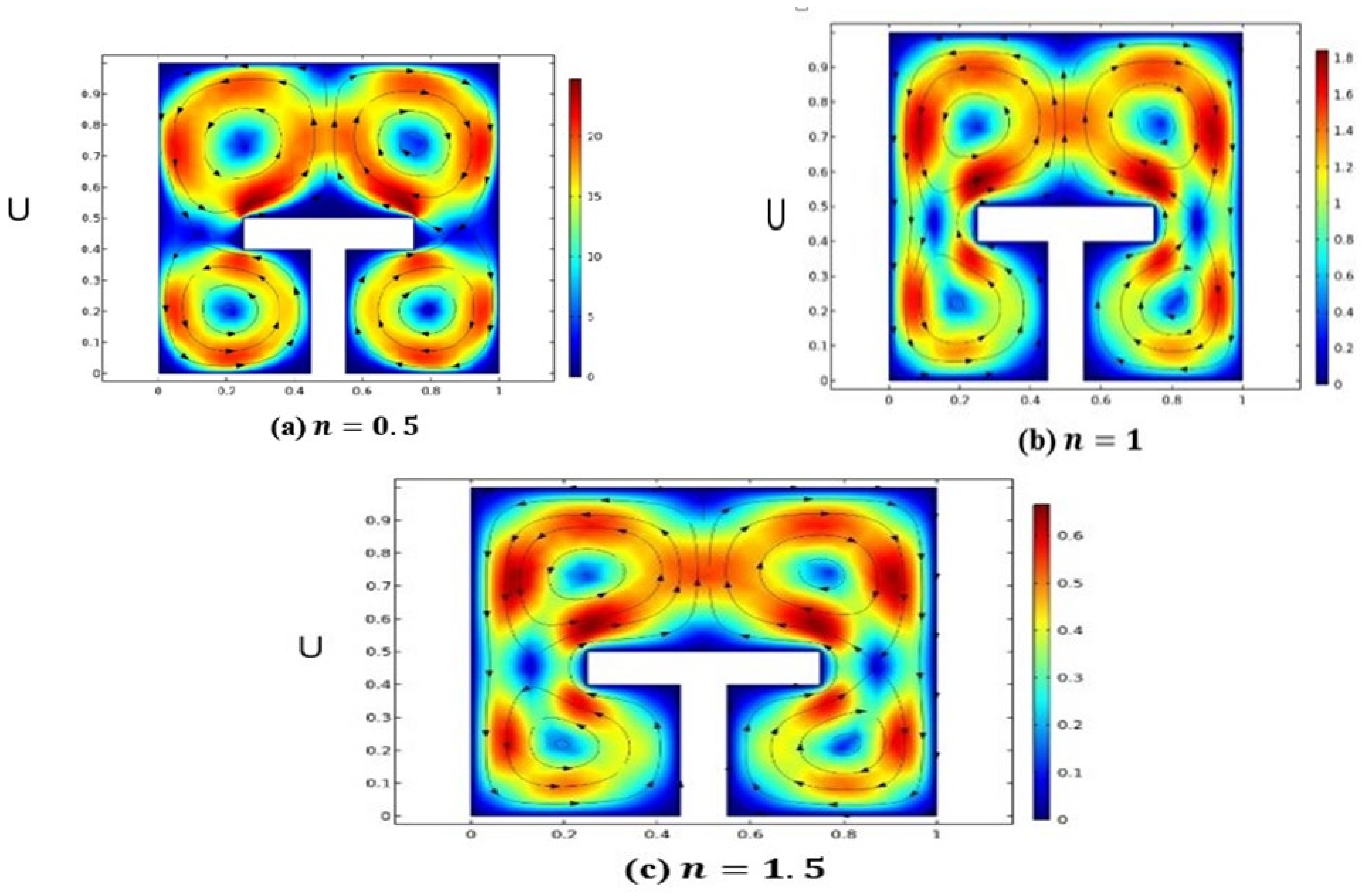
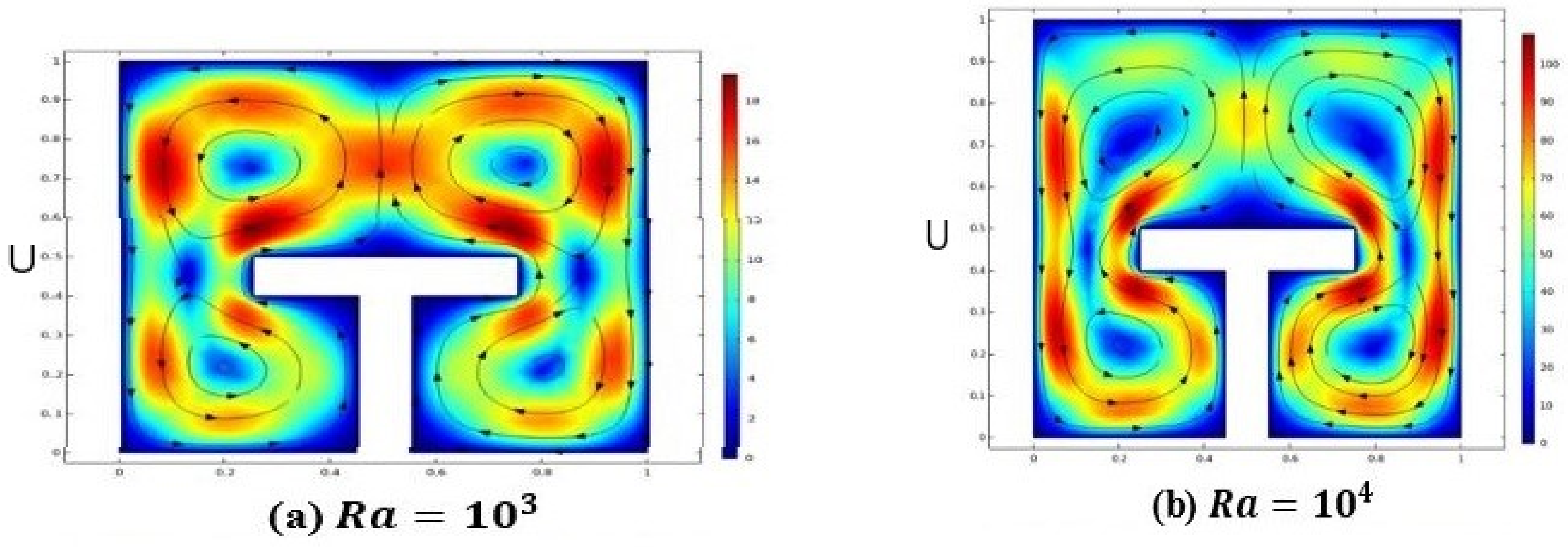
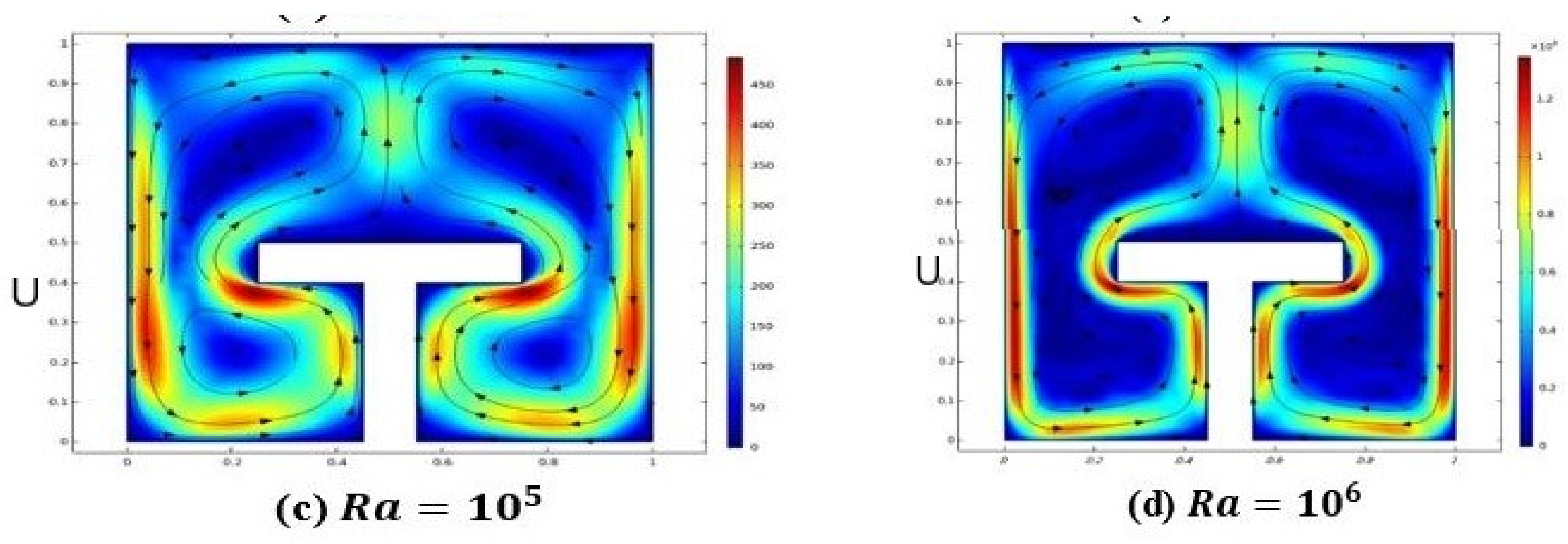
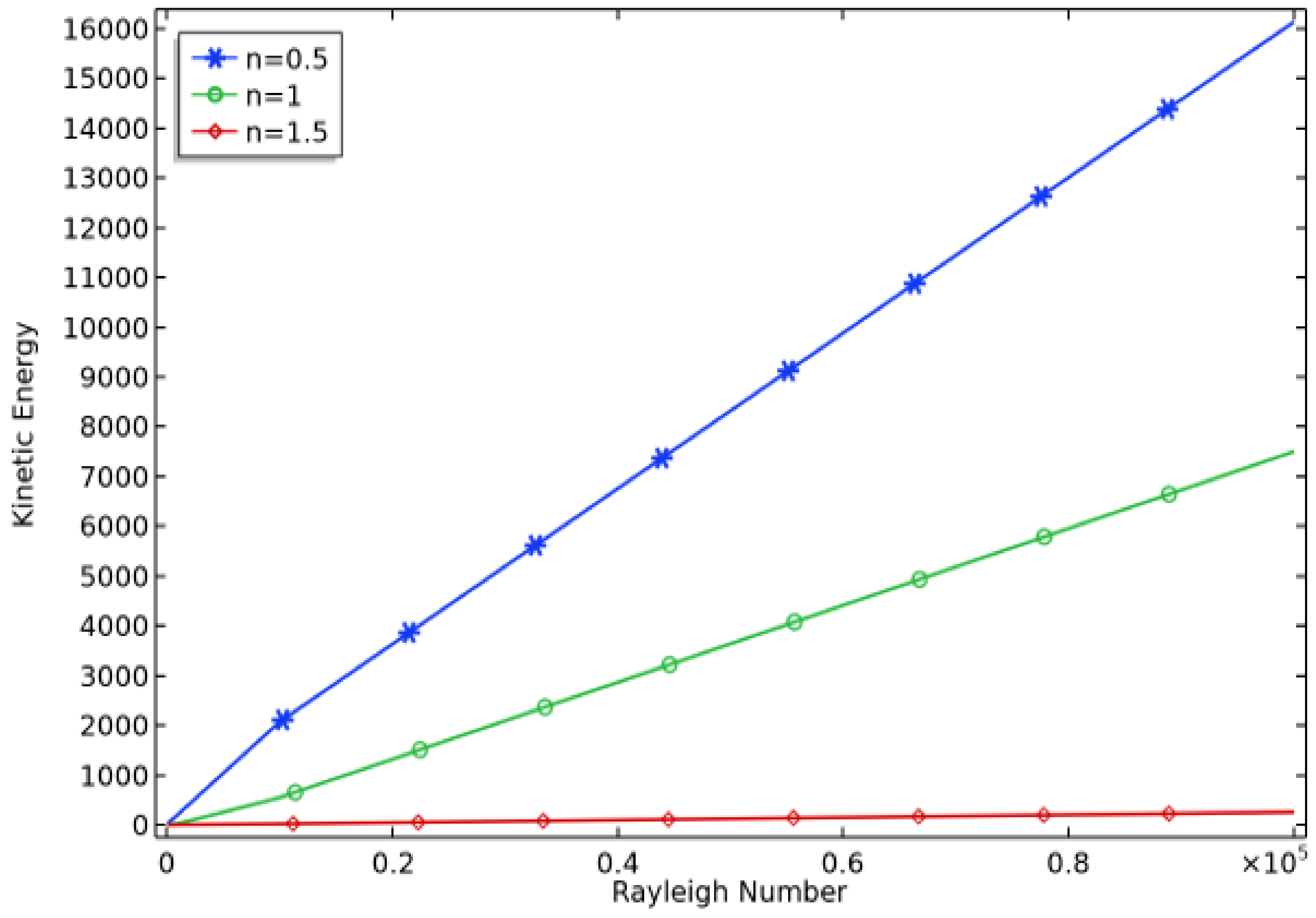
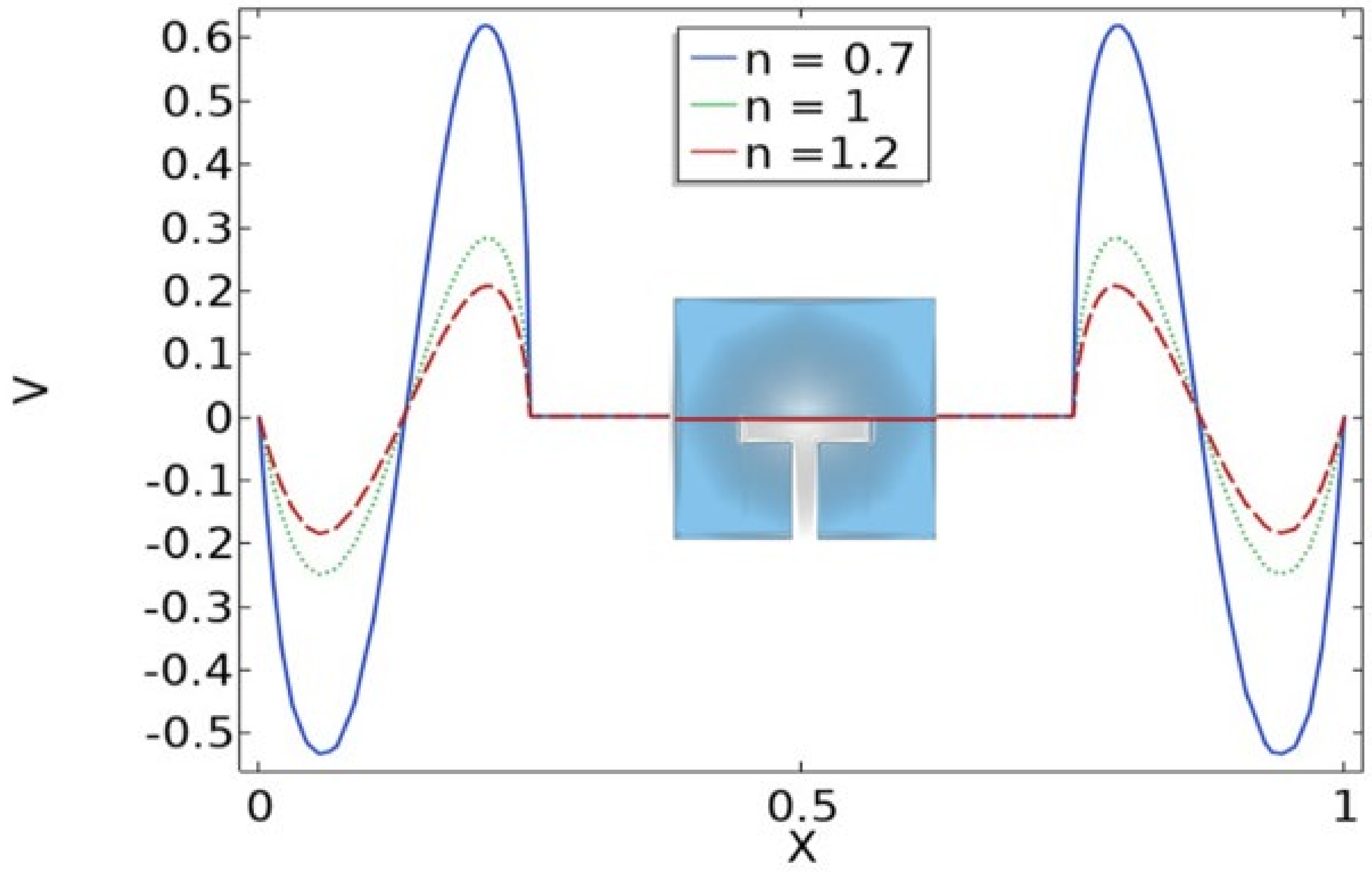
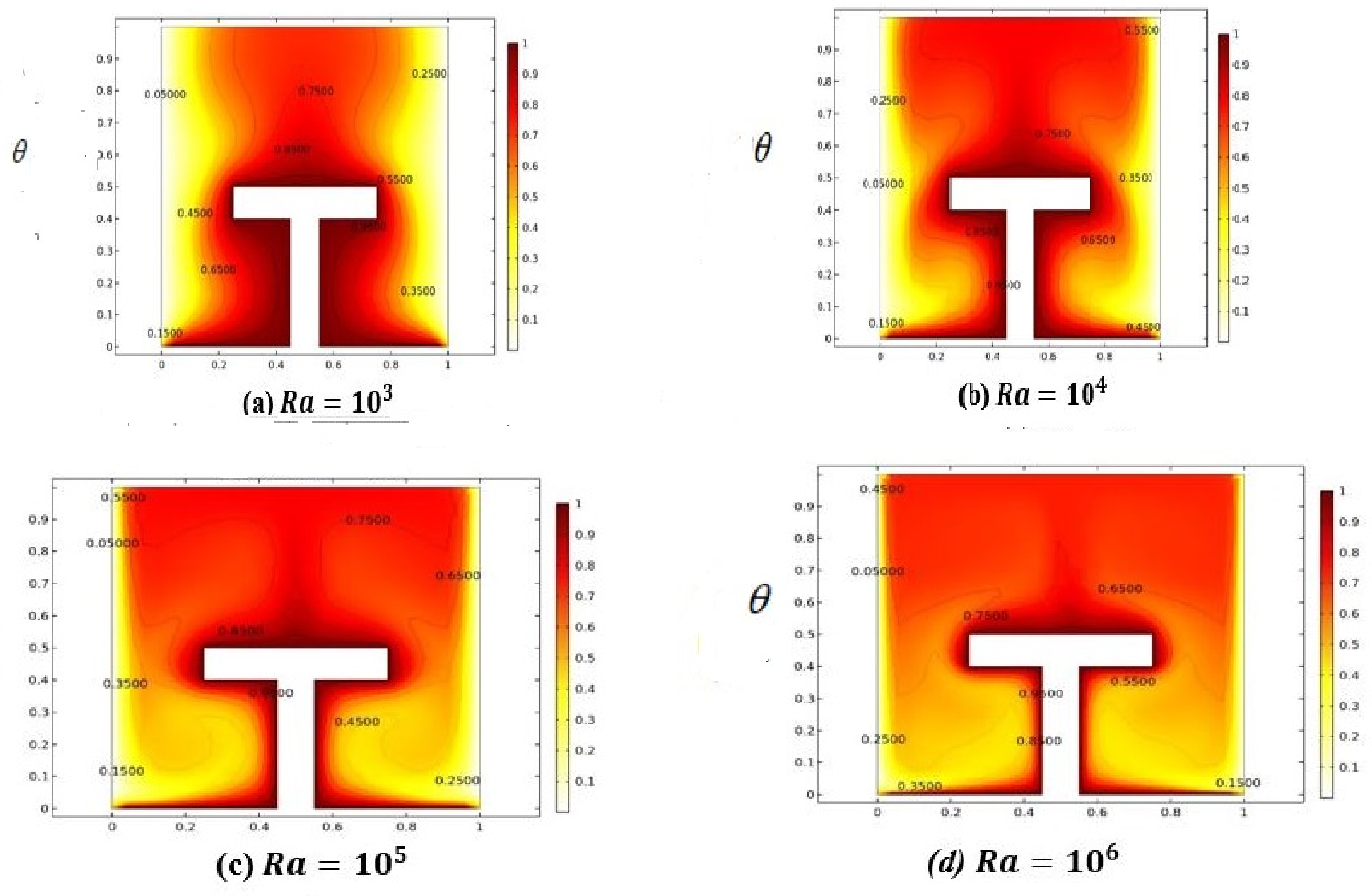
4. Discussion of Results

Results were interpreted by executing the finite element approach via COMSOL Multiphysics software regarding heat transfer attributes of power-law fluid enclosed in a square enclosure including the fitting of a T-shape fin. Deviation in velocity and temperature distribution against different magnitudes of involved parameters like Rayleigh number R a , power-law index n and Prandtl number P r . In addition, local and average heat transfer rates and kinetic energy measurements are enumerated against sundry variables. Variation in the Nusselt number and kinetic energy against the power-law index n is represented in Table 2. It is evaluated that by increasing n , local heat transfer and kinetic energy depreciate because of the fact that by increasing the power-law index fluid behavior changes from shear thinning to thickening. So, as an output fluid viscosity increments slow down the motion and heat transferring process from the flow domain. Deviation in local Nusselt number and kinetic energy against n is evaluated in the form of line charts and is represented in Figure 3, Figure 4 and Figure 5. It is manifested from these sketches that by increasing n the local Nusselt number as well as kinetic energy decreases because of the fact that by increasing n the fluid’s viscosity enriches and causes a reduction in the movement of particles and heat transfer within the flow domain. Table 3 demonstrates the behavior of the Nusselt number against R a and by specifying   ( n < 1 ) ,   n = 1 and   ( n > 1 ) . The increasing trend in the Nusselt number is depicted against the Rayleigh number R a , whereas it is also disclosed that the magnitude of the Nusselt number is greater in the shear thinning case, i.e., n < 1 , than n > 1 . This behavior is evidenced by the fact that an increment in R a increases thermal buoyancy forces due to which heat is transferred within the flow domain from one part of the enclosure to the other. Table 4 exhibits the change in kinetic energy against R a , fixing n = 0.5 ,   1 ,   1.5 . By increasing R a ranging from   10 2 10 5 kinetic energy increments abruptly. This is because of the fact that by varying R a molecular diffusion occurs quickly due to temperature difference and hence the global quantity shows elevation. In addition, the magnitude of the kinetic energy for   n = 1 compared to ( n > 1 ) and n < 1 is scrutinized. Figure 6a–c represents the impact power law index n on velocity distribution in the form of stream lines. The velocity profile for ( n = 0.5 ) showing the pseudo-plastic manner of the power-law fluid model is addressed in Figure 6a. The compact circular patterns in the flow field are noticed showing less dominating aspects of viscosity over inertial forces. Subsequently, it is found that fluid particles move with more speed and are dispersed in the form of circular motion around the fin. In Figure 6b,c elliptic shaped deformation zones are produced on all sides of the fin, which represents the dominating effect of viscous forces instead of thermal buoyancy forces. So, from these sketches it is revealed that at a lower magnitude of n , shear stresses generated due to viscous forces are impressive compared to the higher values of n .  Figure 7a–c describes momentum distribution against R a , ranging from   10 4 R a 10 6 . Intensification in stream line formation around the T-shaped fin is found. This is because of the fact that by increasing R a , dominance in the diffusion of particles takes place within the flow, which as an outcome raises the formation of the pattern around the fin. Figure 8a–d displays the behavior of temperature distribution against the increasing value of   R a due to the provision of uniform heating at the fin. It is seen from the corresponding figures that by increasing the magnitude of   R a , sharpness in the temperature profile is produced due to the enrichment in thermal driven buoyancy forces. In addition, it is worthwhile to mention that heat diffuses more quickly for higher magnitudes of R a .  Figure 9 expresses the comparative analysis between the average and local Nusselt numbers against flow behavior index n and P r . It is manifested that by increasing (n) and (Pr) the magnitude of local heat flux generated by the provision of uniform heating is extensive compared to the measurement of the average Nusselt number within the whole domain. Here, it is also measured that, by increasing (Pr), the Nusselt number is enhanced because the momentum of the fluid raises compared to the thermal diffusion, whereas contrary behavior in the heat flux against (n) is communicated for both local and average Nusselt numbers. Variation in kinetic energy against   R a and for different n values by drawing a cutline at X = 0.5 is displayed in Figure 10. It is scrutinized that the magnitude of kinetic energy for n = 0.5 against variation in (Ra) is comparatively higher than for n = 1 and   ( n = 1.5 ). In addition, it is illustrated that for (Ra = 0), kinetic approaches to zero due to the absence of temperature difference within the enclosure. Variation in kinetic is given in Table 5.
Variation in the vertical component of velocity by drawing the cutline at Y = 0.5 is inspected for different values of   n in Figure 11. In this sketch, the motion of the power-law fluid is expressed in the form of wave structures against three different magnitudes of n , i.e., n = 0.5, 1, 1.5, showing shear thinning, Newtonian and shear thickening aspects, respectively. It is analyzed from the sketch that velocity along a cutline varies in a wave form and a greater increase in the peaks of the profile is observed in the case of n = 0.5 than n = 1 and n = 1.5. In view of gaining an exclusive view concerning maxima or minima of velocity profiles it is observed that absolute maxima are achieved at   X = 0.21 and   X = 0.79 , whereas absolute minima are achieved at   X = 0.005 and   X = 0.95 .

5. Conclusions

The current disquisition analyzes the thermal attributes of the power-law liquid enclosed in a square cavity with the insertion of a uniformly heated T-fin. The formulation of the problem is demonstrated in the context of intricate dimensionless partial differential structuring. Finite element based software known as COMSOL is used to simulate results. Some salient outcomes are enlisted as below:
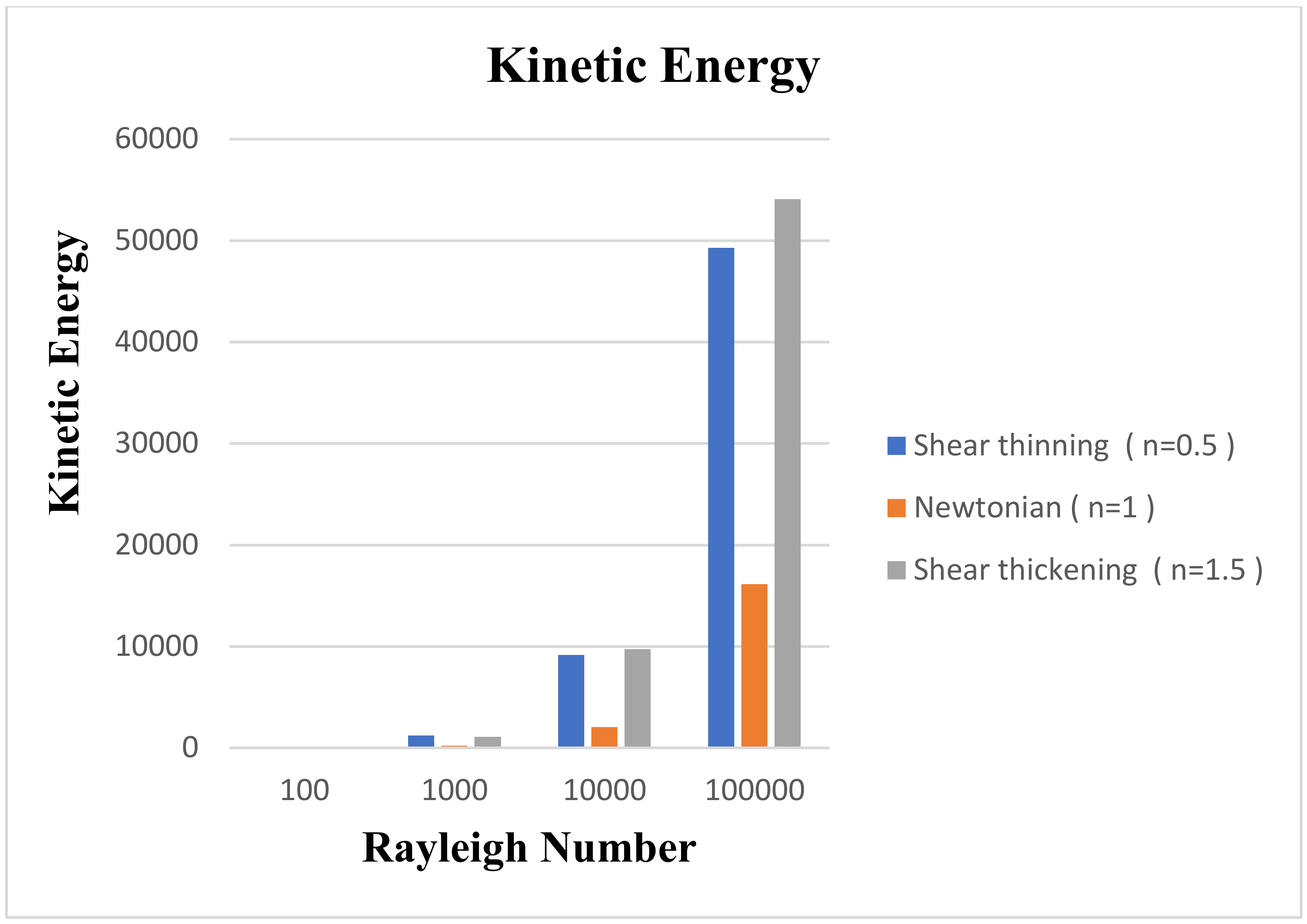
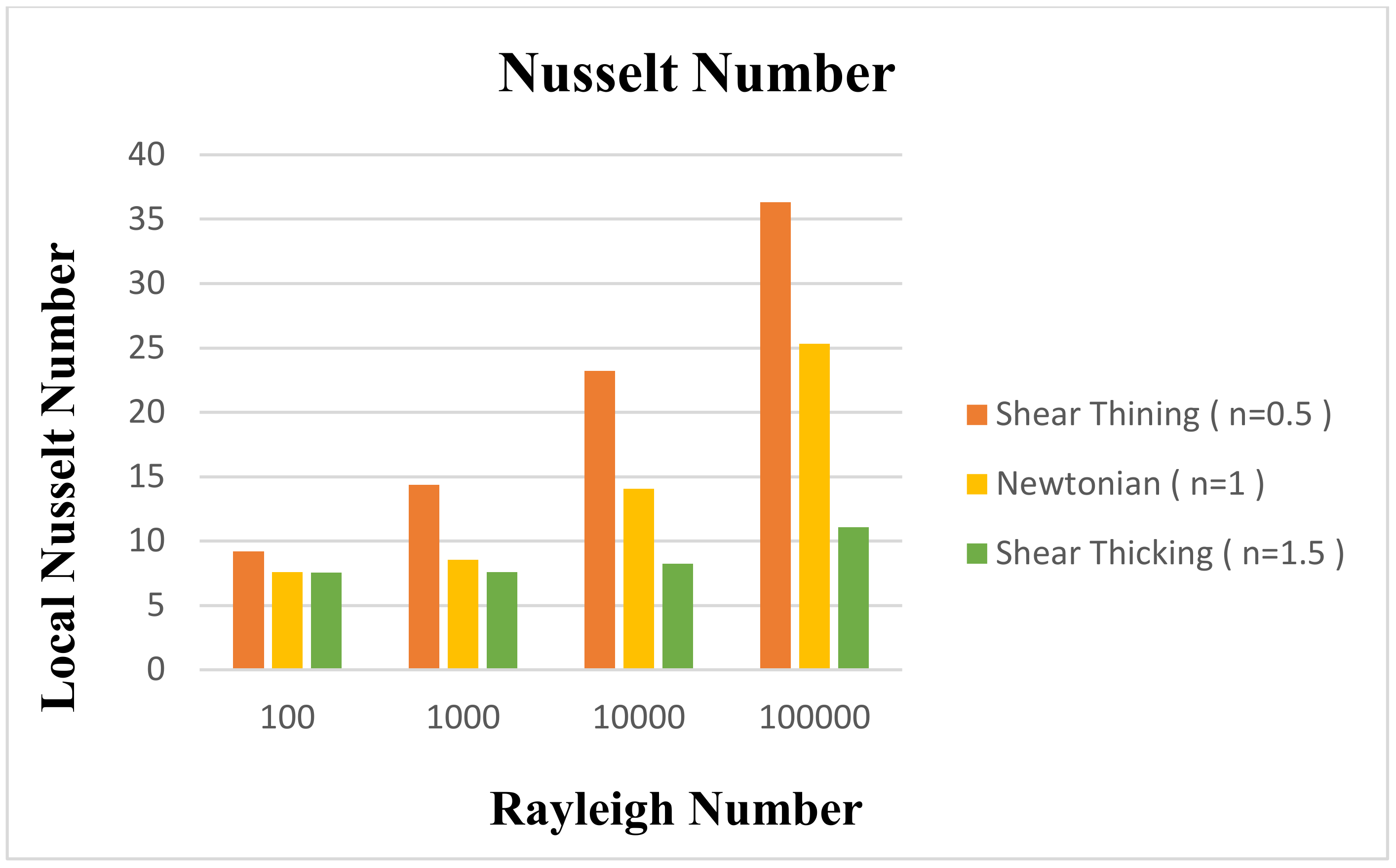
It is inferred that kinetic energy and heat flux coefficient increase with an increase in the Rayleigh number.
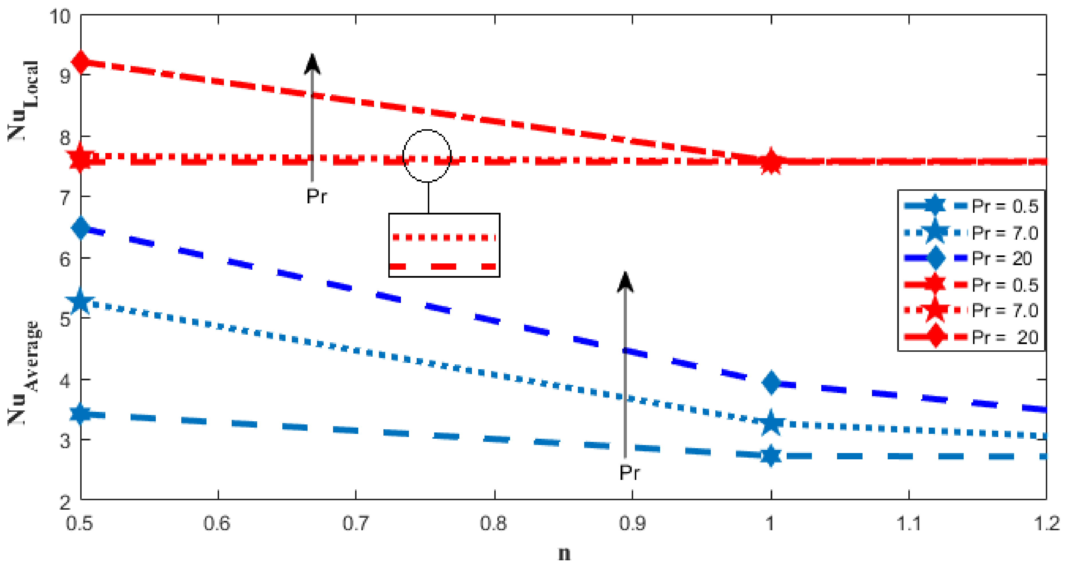
It is deduced that the increment in the power-law index decreases the kinetic energy and local and average Nusselt numbers.
The magnitude of kinetic energy and Nusselt number for shear thinning fluid is comparatively higher than for shear thickening and Newtonian cases.
Increase in temperature distribution is observed against the Rayleigh number due to the generation of temperature differences.
Local and average heat transfer coefficients enhance with increases in the Prandtl number.
Magnitude of heat transmission enriches with an increase in the Rayleigh number.

Author Contributions

Formal analysis, S.B., M.B.R., N.Z.K. and I.A.S.; Funding acquisition, M.B.R.; Investigation, A.A.; Methodology, N.Z.K. and I.A.S.; Writing-review & editing, J.A. and M.B.R. All authors have read and agreed to the published version of the manuscript.

Funding

This work has been supported by the Polish National Science Centre under the grant OPUS 18 No. 2019/35/B/ST8/00980.

Institutional Review Board Statement

Not applicable.

Informed Consent Statement

Not applicable.

Data Availability Statement

Not applicable.

Conflicts of Interest

The authors declare no conflict of interest.

References

  1. Eckert, E.R.G.; Carlson, W.O. Natural Convection in an Air Layer Enclosed Between Two Vertical Plates with Different Temperatures. Int. J. Heat Mass Transf. 1961, 2, 106–120. [Google Scholar] [CrossRef]
  2. Newell, M.E.; Schmidt, F.W. Heat Transfer by Laminar Natural Convection within Rectangular Enclosures. ASME J. Heat Transf. 1970, 92, 159–168. [Google Scholar] [CrossRef]
  3. Bonnett, W.S.; McIntire, V.L. Dissipation effects in hydrodynamic stability of viscoelastic fluids. AIChE J. 1975, 21, 901–910. [Google Scholar] [CrossRef]
  4. Tamotsu, H.; Utaro, I.; Teiriki, T. Heat Transfer by Natural Convection in an Enclosed Cavity—A Part of Bottom is Heated. Kagaku Kogaku Ronbunshu 1975, 1, 450–453. [Google Scholar]
  5. Flack, R.D.; Konopnicki, T.; Rooke, J.H. The measurement of natural convective heat transfer in triangular enclosures. J. Heat Transf. 1979, 101, 770–782. [Google Scholar] [CrossRef]
  6. Davis, G.D.V. Natural convection of air in a square cavity: A bench mark numerical solution. Int. J. Num. Methods Fluids 1983, 3, 249–264. [Google Scholar] [CrossRef]
  7. Hasnaoui, M.; Bilgen, E.; Vasseur, P. Natural convection heat transfer in rectangular cavities heated from below. J. Thermophys. Heat Transf. 1992, 38, 255–264. [Google Scholar] [CrossRef]
  8. Aydin, O.; Yang, J. Natural convection in enclosures with localized heating from below and symmetrical cooling from sides. Int. J. Numer. Methods Heat Fluid Flow 2000, 10, 518–529. [Google Scholar] [CrossRef]
  9. Shojaeian, M.; Kosar, A. Convective heat transfer and entropy generation analysis on Newtonian and non-Newtonian fluid flows between parallel-plates under slip boundary conditions. Int. J. Heat Mass Transf. 2014, 70, 664–673. [Google Scholar] [CrossRef]
  10. Sharif, M.A.R.; Mohammad, T.R. Natural convection in cavities with constant flux heating at the bottom wall and isothermal cooling from the sidewalls. Int. J. Therm. Sci. 2005, 44, 865–878. [Google Scholar] [CrossRef]
  11. Alebrahim, A.; Bejan, A. Constructal trees of circular fins for conductive and convective heat transfer. Int. J. Heat Mass Transf. 1999, 42, 3585–3597. [Google Scholar] [CrossRef]
  12. Almogbel, M.; Bejan, A. Cylindrical trees of pin fins. Int. J. Heat Mass Transf. 2000, 43, 4285–4297. [Google Scholar] [CrossRef]
  13. Kraus, A.D.; Aziz, A.; Welty, J.R. Extended Surface Heat Transfer; John Wiley: New York, NY, USA, 2002. [Google Scholar]
  14. Lorenzini, G.; Biserni, C.; Isoldi, L.A.; Dos Santos, E.D.; Rocha, L.A.O. Constructal design applied to the geometric optimization of Y-shaped cavities embedded in a conducting medium. J. Electron. Packag. 2011, 133, 041008. [Google Scholar] [CrossRef]
  15. Abdi, A.; Martin, V.; Chiu, J.N. Numerical investigation of melting in a cavity with vertically oriented fins. Appl. Energy 2019, 235, 1027–1040. [Google Scholar] [CrossRef]
  16. Bendaraa, A.; Charafi, M.M.; Hasnaoui, A. Numerical study of natural convectionin a differentially heated square cavity filled with nanofluid in the presence of fins attached to walls in different locations. Phys. Fluids 2019, 31, 5355. [Google Scholar] [CrossRef]
  17. Shi, X.; Khodadadi, J.M. Laminar natural convection heat transfer in a differentially heated square cavity due to a thin fin on the hot wall. J. Heat Transf. 2003, 125, 624–634. [Google Scholar] [CrossRef]
  18. Horbach, C.D.S.; dos Santos, E.D.; Isoldi, L.A.; Rocha, L.A.O. Constructal design of Y-shaped conductive pathways for cooling a heat-generating body. Defect Diffus. Forum 2014, 348, 245–260. [Google Scholar] [CrossRef]
  19. Rehman, K.; Kouz, W.A.; Sherif, E.S.; AbdelMalek, Z. Hybrid meshed analysis on rhombus shaped solid material domain (RSSMD) equipped with non-Newtonian liquid stream. J. Sci. Adv. Mater. 2020, 5, 476–486. [Google Scholar] [CrossRef]
  20. Tavana, M.; Pourmehran, O.; Aghaei, A.; Sangara, J.A.; Gorji, B.M. Numerical Analysis of Fluid Flow and Heat Transfer in Microchannels with Various Internal Fins. Int. J. Artif. Intell. Mechatron. 2015, 3, 2320–2331. [Google Scholar]
  21. Scozia, R.; Frederick, R.L. Natural Convection in Slender Cavities with Multiple Fins Attached on an Active Wall. Numer. Heat Transf. 1991, 20, 127–158. [Google Scholar] [CrossRef]
  22. Facas, G.N. Natural Convection in a Cavity with Fins Attached to Both Vertical Walls. J. Thermophys. Heat Transf. 1993, 7, 555–560. [Google Scholar] [CrossRef]
  23. Bahiraei, M.; Heshmatian, S.; Goodarzi, M.; Moayedi, H. CFD analysis of employing a novel ecofriendly nanofluid in a miniature pin fin heat sink for cooling of electronic components: Effect of different configurations. Adv. Powder Technol. 2019, 30, 2503–2516. [Google Scholar] [CrossRef]
  24. Li, Z.; Sarfaraz, M.M.; Mazinani, A.; Hayat, T.; Alsulami, H. Pool boiling heat transfer to CuO-H2O nanofluid on finned surfaces. Int. J. Heat Mass Transf. 2020, 156, 119780. [Google Scholar] [CrossRef]
  25. Ozoe, H.; Churchill, S.W. Hydrodynamic stability and natural convection in Ostwald–de Waele and Ellis fluids: The development of a numerical solution. AIChE J. 1972, 18, 1196–1207. [Google Scholar] [CrossRef]
  26. Kaddiri, M.; Naïmi, M.; Raji, A.; Hasnaoui, M. Rayleigh Benard convection of non-Newtonian power-law fluids with temperature-dependent viscosity. ISRN Thermodyn. 2012, 2012, 10. [Google Scholar] [CrossRef] [Green Version]
  27. Kim, G.B.; Hyun, J.M.; Kwak, H.S. Transient buoyant convection of a power-law non-Newtonian fluid in an enclosure. Int. J. Heat Mass Transf. 2003, 46, 3605–3617. [Google Scholar]
  28. Makayssi, T.; Lamsaadi, M.; Naïmi, M.; Hasnaoui, M. Natural convection heat transfer in shallow horizontal rectangular enclosures uniformly heated from the side and filled with non-Newtonian power law fluids. Energy Convers. Manag. 2006, 47, 2535–2551. [Google Scholar]
  29. Abderrahmane, H.; Brahim, N.; Abdelfatah, B.; Nouereddine, A.M. Laminar natural convection of power-law fluid in a differentially heated inclined square cavity. Ann. Chim.-Sci. Mat. 2017, 41, 261–281. [Google Scholar] [CrossRef]
  30. Khezzar, L.; Siginer, D.; Vinogradov, I. Natural convection of power law fluids in inclined cavities. Therm. Sci. 2017, 53, 8–17. [Google Scholar] [CrossRef]
  31. Turan, O.; Sachdeva, A.; Chakraborty, N.; Poole, R.J. Laminar natural convection of power-law fluids in a square enclosure with differentially heated side walls subjected to constant temperatures. J. Non-Newton. Fluid Mech. 2011, 166, 1049–1063. [Google Scholar] [CrossRef]
  32. Ternik, P.; Rudolf, R. Laminar natural convection of non-Newtonian nanofluid in a square enclosure whit differentially heated side walls. Int. J. Simul. Modeling 2013, 12, 5–16. [Google Scholar] [CrossRef]
  33. Sojoudi, A.; Saha, S.C.; Gu, Y.; Hossain, M.A. Steady natural convection of non-Newtonian power-law fluid in a trapezoidal enclosure. Adv. Mech. Eng. 2013, 53, 653–668. [Google Scholar] [CrossRef] [Green Version]
  34. Turan, O.; Sachdeva, A.; Poole, R.J.; Chakraborty, N. Aspect ratio and boundary conditions effects on laminar natural convection of power-law fluids in a rectangular enclosure with differentially heated side walls. Int. J. Heat Mass Transf. 2013, 60, 722–738. [Google Scholar] [CrossRef]
  35. Ternik, P.; Buchmeister, J. Buoyacy-induced flow and heat transfer of power law fluids in a side heated square cavity. Int. J. Simul. Model. 2015, 14, 238–249. [Google Scholar] [CrossRef]
  36. Alloui, Z.; Vasseur, P. Natural convection of Carreau–Yasuda non-Newtonian fluids in a vertical cavity heated from the sides. Int. J. Heat Mass Transf. 2015, 84, 912–924. [Google Scholar] [CrossRef]
  37. Nirmalkar, N.; Chhabra, R.P.; Poole, R.J. Effect of shear-thinning behavior on heat transfer from a heated sphere in yield-stress fluids. Ind. Eng. Chem. Res. 2017, 53, 13490–13504. [Google Scholar] [CrossRef]
  38. Ouertatani, N.; Ben Cheikh, N.; Ben Beya, B.; Lili, T. Numerical simulation of two-dimensional Rayleigh–Bénard convection in an enclosure. Comptes Rendus Mécanique 2008, 336, 464–470. [Google Scholar] [CrossRef]
  39. Roy, S.; Basak, T. Finite element analysis of natural convection flows in a square cavity with non-uniformly heated wall(s). Int. J. Eng. Sci. 2005, 43, 668–680. [Google Scholar] [CrossRef]
  40. Nirmalkar, N.; Gupta, A.K.; Chhabra, R.P. Natural Convection from a Heated Sphere in Bingham Plastic Fluids. Ind. Eng. Chem. Res. 2014, 53, 17818–17832. [Google Scholar] [CrossRef]
  41. Gupta, S.; Patel, S.A.; Chhabra, R.P. Pulsatile flow of power-law fluids over a heated cylinder: Flow and heat transfer characteristics. Int. J. Therm. Sci. 2020, 152, 106330. [Google Scholar] [CrossRef]
  42. Mishra, L.; Chhabra, R.P. Combined effects of fluid yield stress and geometrical arrangement on natural convection in a square duct from two differentially heated horizontal cylinders. J. Therm. Sci. Eng. Appl. 2020, 011016. [Google Scholar] [CrossRef]
  43. Sasmal, C.; Gupta, A.K.; Chhabra, R.P. Natural convection heat transfer in a power-law fluid from a heated rotating cylinder in a square duct. Int. J. Heat Mass Transf. 2020, 1, 975–996. [Google Scholar] [CrossRef]
  44. Mishra, L.; Chhabra, R.R. Natural convection in power-law fluids in a square enclosure from two differentially heated horizontal cylinders. Heat Transf. Eng. 2018, 39, 819–842. [Google Scholar] [CrossRef]
  45. Raisi, A. Natural Convection of Non-Newtonian Fluids in a Square Cavity with a Localized Heat Source. Stroj. Vestnik/J. Mech. Eng. 2016, 62, 10–22. [Google Scholar] [CrossRef]
Figure 1. Graphical illustration of the problem.
Mathematics 10 00342 g001
Figure 2. Mesh analysis at finer level.
Mathematics 10 00342 g002
Figure 3. Comparison of stream lines and isothermal contours with Roy and Basak [39].
Mathematics 10 00342 g003aMathematics 10 00342 g003b
Figure 4. Variation in Local Nusselt number against (n) at X = 0.5.
Mathematics 10 00342 g004
Figure 5. Line chart for variation in kinetic energy against (n) at X = 0.5.
Mathematics 10 00342 g005
Figure 6. Variation in velocity distribution against (n).
Mathematics 10 00342 g006
Figure 7. Variation in velocity distribution against (Ra).
Mathematics 10 00342 g007aMathematics 10 00342 g007b
Figure 8. Variation in temperature distribution against (Ra).
Mathematics 10 00342 g008
Figure 9. Variation in Nusselt number against (Pr) and (n).
Mathematics 10 00342 g009
Figure 10. Variation in kinetic energy against (Ra) and (n) at X = 0.5.
Mathematics 10 00342 g010
Figure 11. Cutlines for V at Y = 0.5.
Mathematics 10 00342 g011
Table 1. Grid independence test at different refinement levels.
LevelsNumber of ElementsDegree of Greedom N u L o c a l Kinetic Energy
Extremely Coarse45412645.7142 8.8560 × 10 5
Extra Coarse66018086.2082 9.6805 × 10 5
Coarser100826366.6154 1.0247 × 10 4
Coarse181245567.2062 1.0625 × 10 4
Normal267565288.5638 1.0894 × 10 4
Fine414797728.8640 1.1283 × 10 4
Finer10,68024,3688.8644 1.1284 × 10 4
Table 2. Comparison of average Nusselt number N u A v g   against ( n ) .
n N u A v g   in   [30] N u A v g   in   [33] N u A v g   in   Present   work
0.66.93457.0206.9872
0.85.51275.6200
1.04.69933.7414.6990
1.23.17093.1705
1.43.78693.7703.7870
Table 3. Variation of Nusselt Number and Kinetic Energy with power-law index (n).
Power Law Index (n)Local Nusselt NumberKinetic Energy
0.5 9.214687249105.4262823501
1 7.57983334434.408781197
1.5 7.56685379995.137400379
Table 4. Variation in local Nusselt number against (n) and (Ra) at X = 0.5.
RaShear Thinning
n = 0.5
Newtonian
n = 1
Shear Thickening
n = 1.5
1009.2147.5797.566
100014,3648.5287.607
10,00023,20814,0558.253
100,00036,32225,31111,063
Table 5. Variation in kinetic energy against (n) and (Ra) at X = 0.5.
Rayleigh NumberShear Thinning
n = 0.5
Newtonian
n = 1
Shear Thickening
n = 1.5
100105,42634,40895,137
10001,207,006211,4481,076,050
10,0009,173,7152,065,7249,719,185
100,00049,296,47316,134,38354,104,160
Publisher’s Note: MDPI stays neutral with regard to jurisdictional claims in published maps and institutional affiliations.

