Article

Mathematical Correlation Study of Nanofluid Flow Merging Points in Entrance Regions

by
Mostafa Mahdavi
1,
Mohsen Sharifpur
1,2,*,
Magda Abd El-Rahman
3,4 and
Josua P. Meyer
1,5
1
Department of Mechanical and Aeronautical Engineering, University of Pretoria, Pretoria 0002, South Africa
2
Department of Medical Research, China Medical University Hospital, China Medical University, Taichung 404, Taiwan
3
Department of Physics, College of Science, King Khalid University, Abha 61413, Saudi Arabia
4
Department of Radiation Physics, National Center of Radiation Research and Technology (NCRRT), Atomic Energy Authority, Cairo 11787, Egypt
5
Faculty of Mechanical Engineering, Stellenbosch University, Stellenbosch 7602, South Africa
*
Author to whom correspondence should be addressed.
Mathematics 2022, 10(21), 4148; https://doi.org/10.3390/math10214148
Submission received: 27 October 2022 / Revised: 3 November 2022 / Accepted: 4 November 2022 / Published: 6 November 2022
(This article belongs to the Special Issue Mathematical Methods on Mechanical Engineering)

Abstract

:
Here, hydrodynamic features of laminar forced nanofluid flow between two parallel plates are numerically investigated, and the results are mathematically discussed. The conventional understanding of developing flow in the entrance region of internal flows is based on the idea that boundary layers start forming at the inlet and merge at some point just before the fully developed section. However, because of the consideration of mass and flow conservation, the entire conception is required to be detailed with appropriate criteria according to the numerical simulations. Hence, nanofluid flow between two parallel plates is solved by ANSYS Fluent 19.3 for laminar forced in an isothermal condition. Two major criteria are studied to find the location of the boundary layer merging points: vorticity and velocity gradient in a direction perpendicular to the flow. The former presents the influential area of wall shear stress, and the latter is the direct infusion of the boundary layer induced by the solid walls. Vorticity for an irrotational flow is obtained by calculating the curl of the velocity. It is found that the merging points for the hydrodynamic boundary layers are considered before the fully developed region. For the first time, in this study, the results of various Reynolds numbers are collected, and correlations are proposed to predict the length of the boundary layer merging location by using a regression analysis of the data.

1. Introduction

There is no doubt that the boundary layer development caused by the contact between the solid wall and fluid has major impacts on the hydrodynamic and thermal features of the flow field [1,2,3,4,5,6]. In classical fluid mechanics, the uniform flow enters a channel and is affected by the shear stress of the wall, and then the boundary layers coming from all around will merge downstream. This means that two dominant regions can be identified in the internal flows—the entrance region where the boundary layers merge at the end of it, and the fixed velocity profile or fully developed region. Identifying such regions can improve the modelling and analysis of flows in pneumatic and hydraulic systems in many industries, such as gripping devices, as shown by Savkiv et al. [7].
In the conventional sense, it is believed that the entrance region is a direct consequence of the velocity boundary layer formation until the velocity reaches its fixed profile. This sectional division has been repeatedly mentioned in some major academic textbooks, considering the fact that fully developed flow appears immediately or slightly after the boundary layers meet [8,9,10,11,12,13,14]. In addition, because of the short length of the entrance region and the small impact on the average variables in the large section of the fully developed flow, the pre-proven facts from those textbooks were used in many other research areas regarding internal flows and developing sections [15,16,17,18,19].
In any internal flows, such as pipes and ducts, hydrodynamic boundary layers start growing from the walls that touch the fluid, until they meet somewhere downstream. From this point, the boundary layers cannot grow more, and the entire flow needs to adjust accordingly so as to conserve continuity, also known as the Hagen–Poiseuille flow. The flow is normally assumed to be uniform at the inlet of the channel and slows down near the wall due to shear stress. Before all of the surrounding boundary layers meet at the centreline, the core flow is still inviscid and unaware of the shear on the wall. However, it is noted that the velocity in the parallel core flow (inviscid region) and the centreline has to increase because of the conservation of mass.
Because of the importance of the entrance region, especially in heat transfer, researchers have mostly focused on considering the entrance region as one section and analysing its hydrodynamic and thermal characteristics [20,21,22,23,24]. However, there are only a few studies on the analysis of the entrance region by dividing it into different stages [25,26,27,28]. An analytical model was presented by Fargie and Martin [26] in the early 1970′s to explain the behaviour of fluid in the region before the fully developed section. They assumed two velocity functions in the entrance region: an inviscid core region with a parallel velocity changing only in the axial direction, and the region being affected by the viscus boundary layer, yet still a function of the boundary layer thickness and core velocity. Then, a core parallel velocity was proposed in terms of the boundary layer thickness. The total velocity profile was developed in a way that when the boundary layer reached its maximum, the velocity changed into parabolic or second order conventional profile in the fully developed region.
Mohanty and Asthana presented one of the major works regarding the entrance region [27]. They reported that the entrance region was divided into two parts. The first part that the boundary layers induced by the surrounding walls started growing, and they only met at the end of this part. The second section was the fully viscous region where the velocity was still adjusting so as to find its fully developed form eventually. They called these parts the inlet and filled regions, and the combination of these two forms was called the entrance region. To find the starting location of a fully developed region, they used the criterion that the centreline velocity must reach 99% of the fully developed maximum value, which has also been used by others [29]. They showed that the inlet region was less than a quarter of the full entrance length (contrary to the conventional approach), and the entrance length had been under-predicted previously. Nassri and Unny [25] conducted an experimental study to investigate the nature of flow and pressure drop in the entrance region. They also proposed that a fully developed region only reached downstream after the boundary layers met. Their test measurements were found to be in close agreement with the experimental study by Mohanty and Asthana [27] in terms of the total length of the entrance region. The entrance length was expressed in terms of the pipe diameter and Reynold number in the form of LE/D = C × Re. However, Durst et al. [30] proposed a different form for the non-dimensional entrance length by considering power for the Reynolds number.
Adding nanoparticles into different base fluids has been an important study case for researchers in recent years because of the modification in the thermo-physical properties [31,32,33,34,35,36,37,38,39,40,41]. The main applications have been in internal flows with heat transfer. However, attention was paid to the average effects in the fully developed region and not the entrance part [42,43]. Therefore, because of the significance of the entrance region in the boundary layer formation, it is essential to investigate the hydrodynamic features of the nanofluid flow in further detail. The literature review shows that despite some accepted fundamental conceptions about the velocity boundary layers in textbooks, it is critical to question and analyse the entrance region in the internal flows. Because of the improvement in computational fluid dynamics tools in recent years, this task can be carried out with a high accuracy of ANSYS Fluent 19.3 [44]. The results include flow variables and gradients in every computational cell at the vicinity of the wall to the core of the flow.

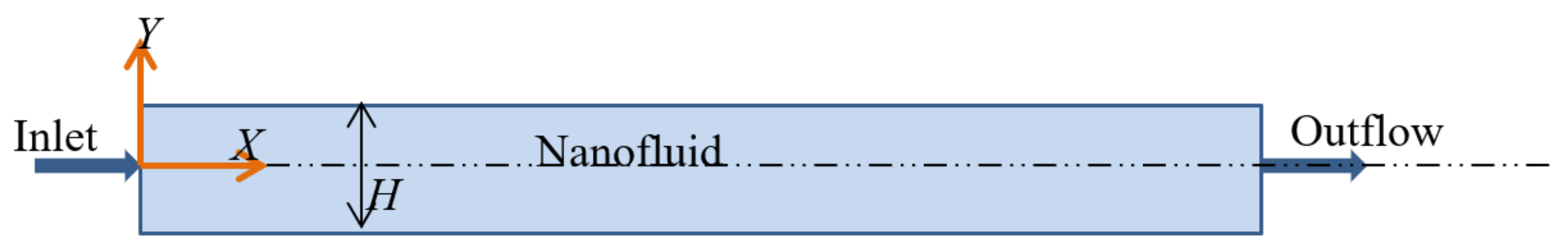
2. Geometry Description and Computational Method

Geometry Details

The purpose of this study is to firstly identify the different sections in the entrance region and secondly to propose a correlation between the location of the boundary layer merging point. Hence, 2D geometry of the nanofluid flow going through two plates was prepared here for the numerical simulations. The total section length was 6 mm, with 4 mm distance between the plates. Nanofluid entered the domain with a uniform velocity profile, and the flow was maintained at isothermal conditions. The general arrangement of the CFD simulation model is presented in Figure 1. To ensure laminar flow was achieved in all of these cases, the Reynolds number was kept under 1900, with a constant inlet temperature of 20 °C.

3. Mathematical Formulation and Nanofluid Properties

Continuity and momentum equations for the nanofluid are expressed here according to the following assumptions: steady laminar flow, two-dimensional, no body force, modified properties, non-Newtonian fluid, and incompressible flow.
u x + v y = 0
ρ u u x + v u y = P x + x μ u x + y μ u y  
ρ u v x + v v y = P y + x μ v x + y μ v y  
With the Reynolds definition:
R e = ρ u D h μ
where D h is hydraulic diameter, defined as:
D h = 4 A P = 4 H × w 2 × H + w
where w is the width of the channel perpendicular to the page. As the channel width is assumed to be long compared with its height, the hydraulic diameter will be D h = 2 H .
Alumina nanofluid was used in this study with an average nanoparticle size of 150 nm and various volume fractions of up to 6% vol. The water and nanoparticles properties are shown in Table 1.
The thermo-physical properties of the nanofluid are borrowed from the literature, with the density from the Sharifpur model [45] and the viscosity from Corcione [46]:
ρ = ρ l 1 φ + 8 φ d p 2 + t v 3 / d p 3
t v = 0.0002833   d p 2 2 + 0.0475 d p 2 0.1417
μ = μ l 1 34.87 d p 0.3 × 10 10 0.3 φ 1.03  

4. Numerical Scheme and Boundary Condition

Continuity and momentum equations were discretized by using a second-order upwind scheme due to the stronger convergence in the solution and the PRESTO! scheme for pressure because of its stability when calculating the pressure on the element faces. The solution algorithm used was the SIMPLE method, or the Semi-Implicit Method for Pressure Linked Equations. This method is used in most CFD simulations and provides fast convergence in the residuals of continuity and momentum. Uniform velocity is used at the inlet with the outflow condition at the outlet, which represents a fully developed flow condition. A no-slip boundary condition was applied to both parallel plates. As the flow was laminar, no boundary layer mesh was needed. A uniform structured mesh was generated at the inlet with 33 × 1363 nodes in the vertical direction and flow direction, respectively, with a total of 45,000 computational cells. The resolution for the laminar flow is normally smaller than this number of cells; however, for the purpose of this simulation and for extraction variables such as velocity gradient and vorticity, it was crucial to opt for a finer grid structure.

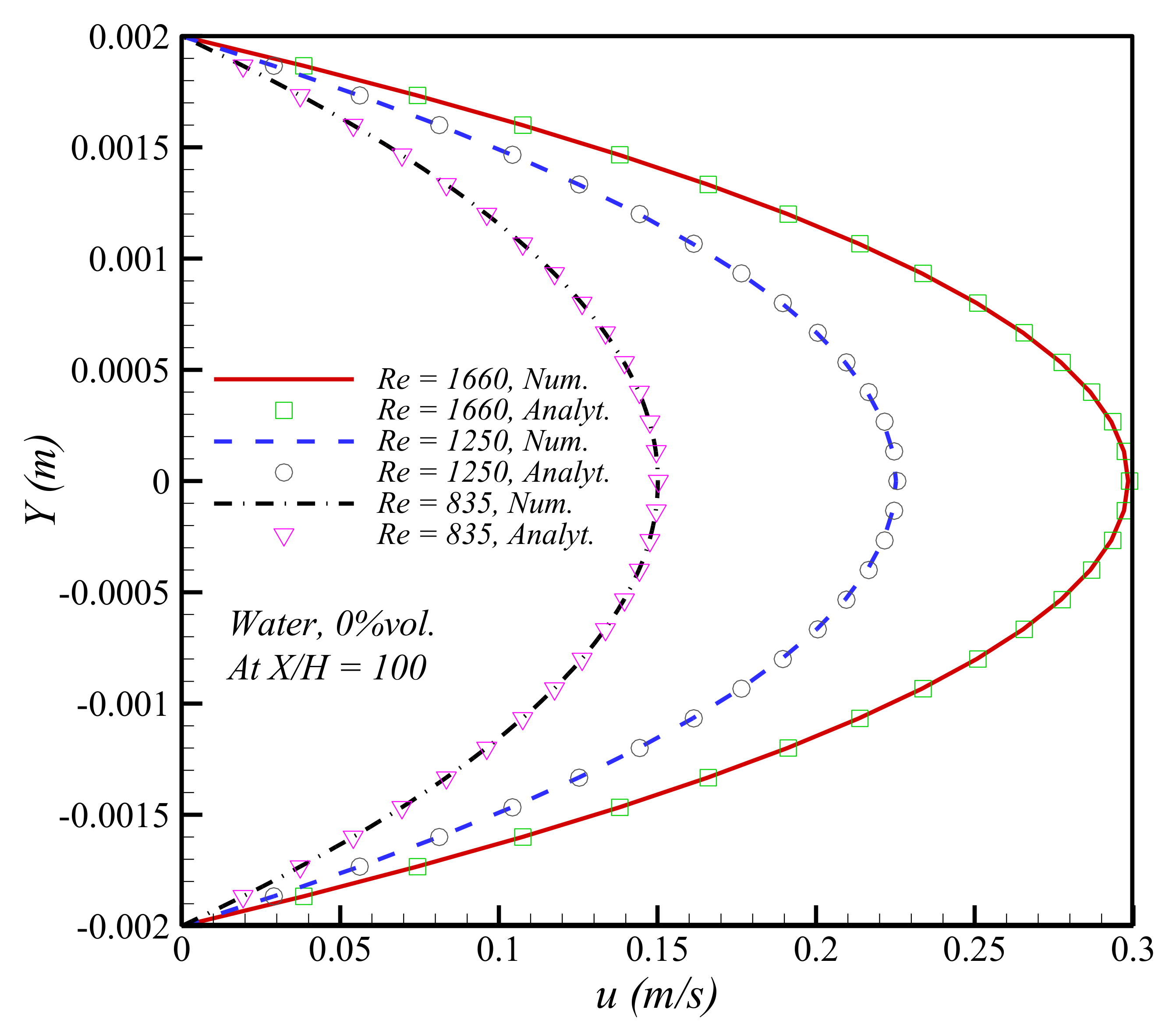
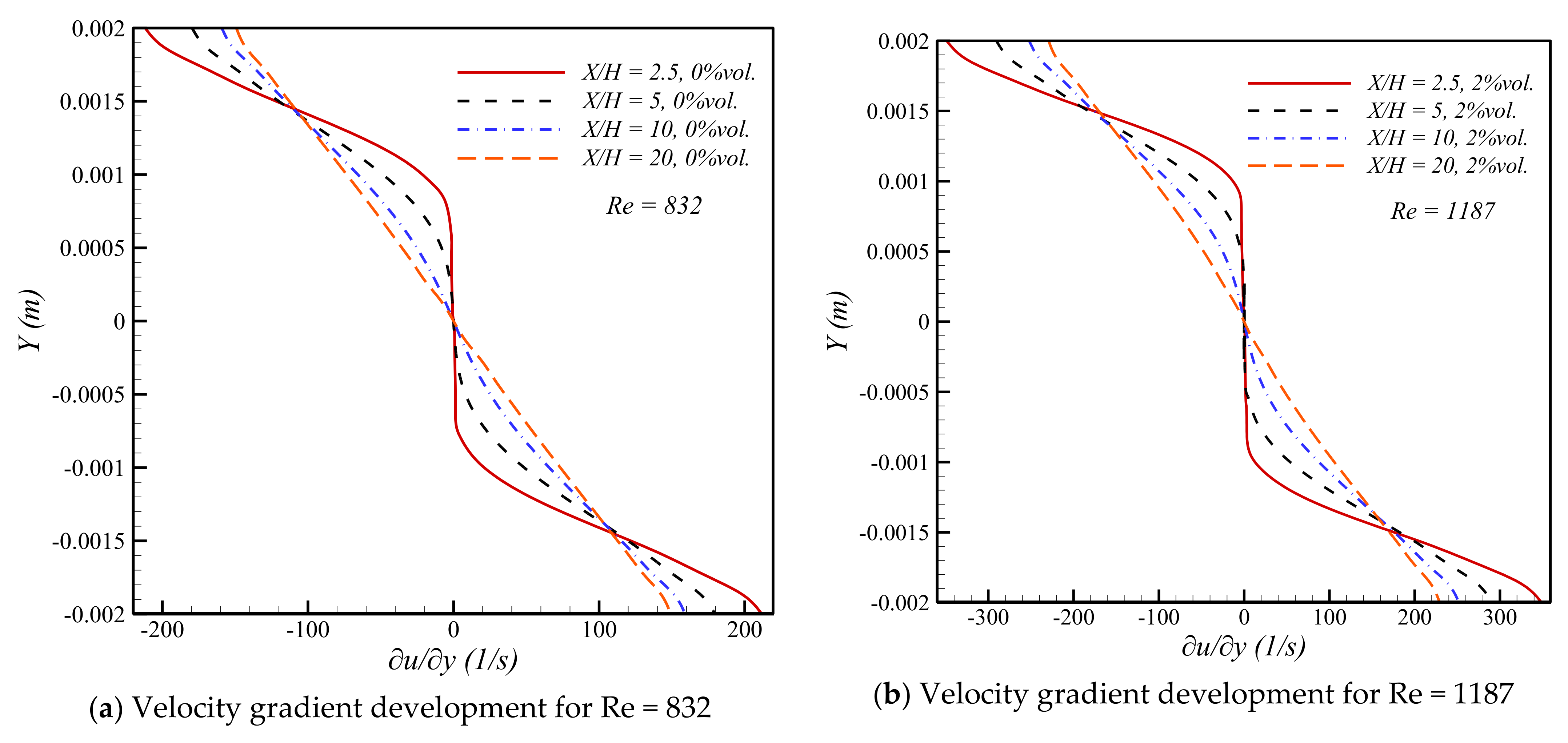
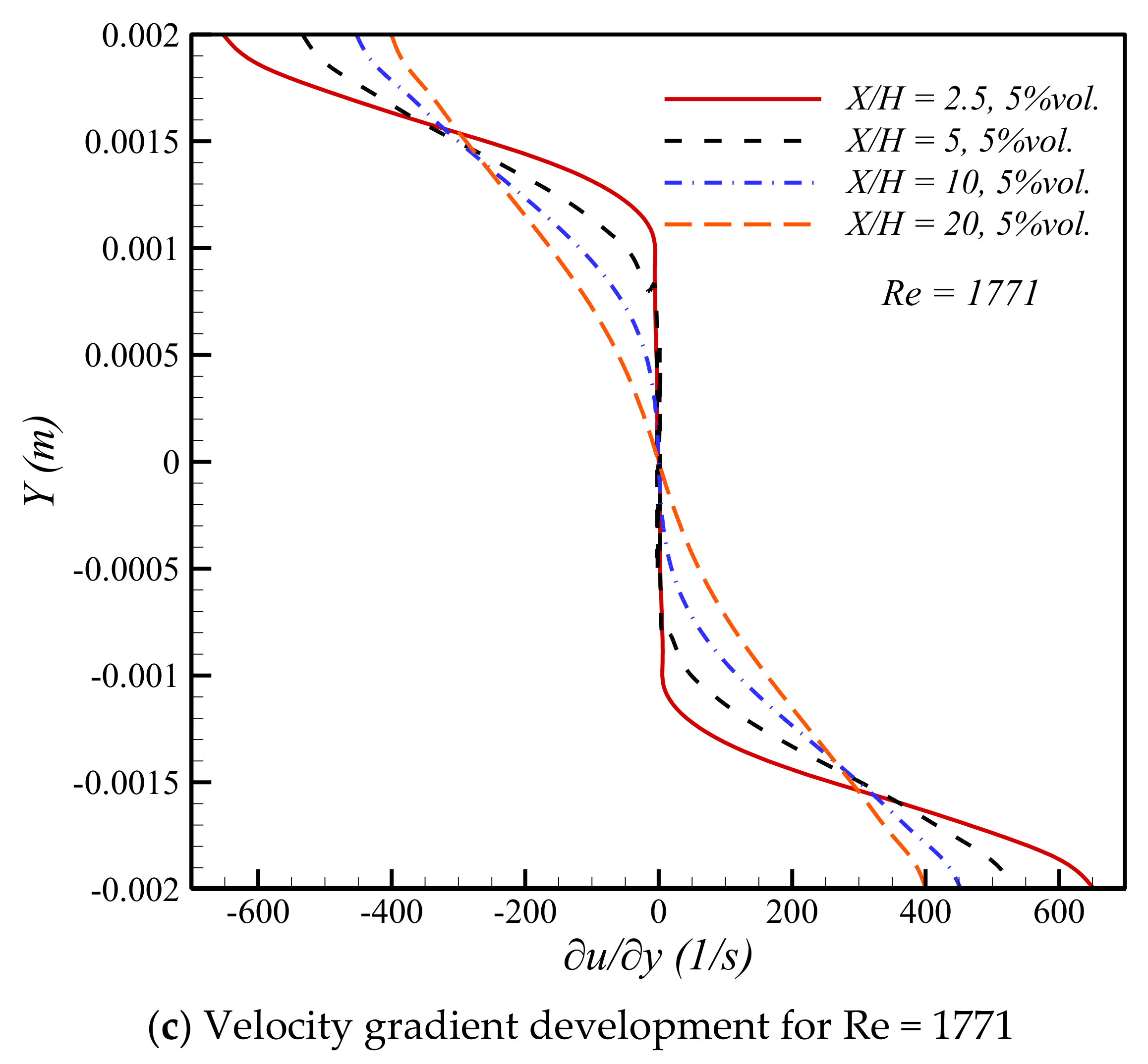
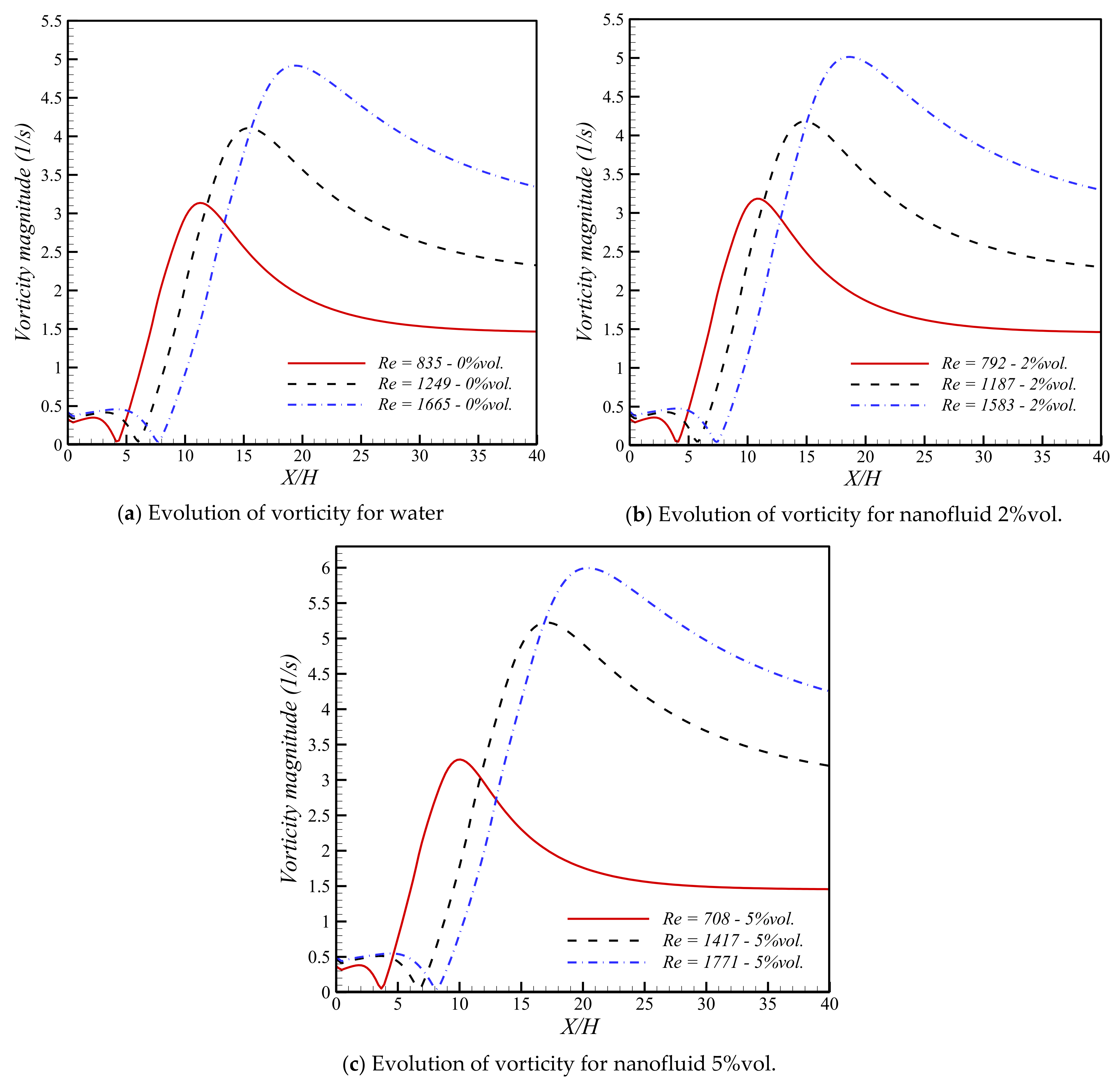
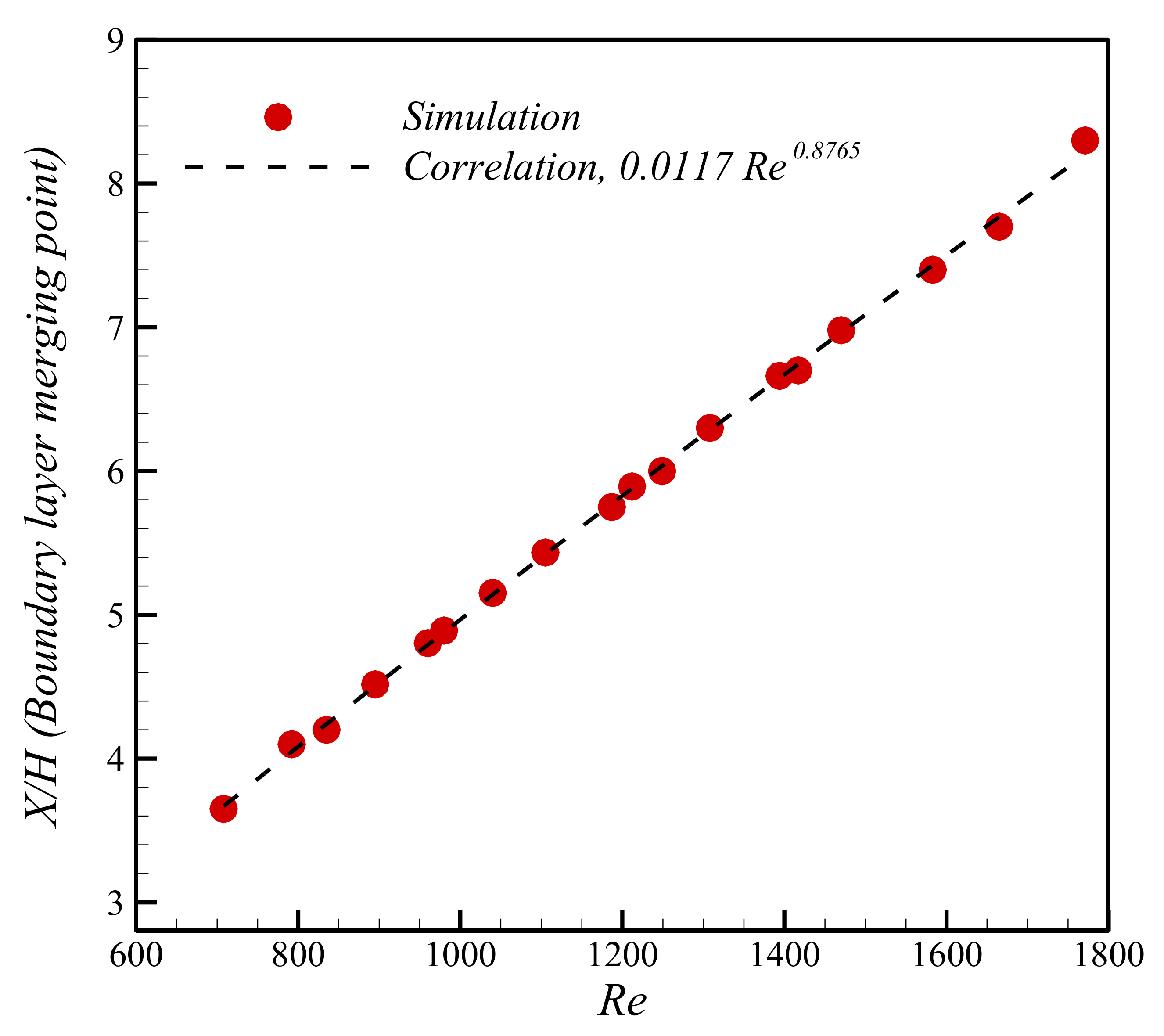
5. Results and Discussion

In the first step, it was essential to validate the modelling against a benchmark available in the literature. Therefore, a highly structured mesh was generated, and the results for the velocity profile in the fully developed region were compared to the available analytical profile in the mechanical engineering textbook [8] for the flow between two parallel plates. The results were found to be in excellent agreement, as shown in Figure 2.
The results of the velocity gradient in the flow direction are illustrated in Figure 3. As the flow at the core region was not affected until the boundary layers merged, the changes in this velocity gradient were caused by the growing boundary layers toward the centre of the channel, similar to the converging diffuser. There was an initial sharp increase due to the beginning of the boundary layer, and the gradient was adjusted according to the shear layer increase by dropping gradually. The location where the rate of the velocity gradient started changing direction is the merging point of the boundary layer. In addition, it was observed that adding nanoparticles could shift the magnitude of the velocity gradient.
The velocity gradient perpendicular to the flow direction is shown in Figure 4 for various nanofluid concentrations. Theoretically, the velocity gradient in the Y direction only appeared inside the boundary layer, and it was expected to reach zero in the inviscid core region with a parallel flow. This could be used as one of the criteria to find the boundary layer merging point. In other words, the merging point will be the first location where the gradient value is non-zero everywhere in the Y direction, except at the centre (due to the symmetry condition).
Despite the strong logic behind the velocity gradient in Figure 4 for finding the merging point, it still seems challenging to point out the exact location considering the shape of the graph. Although the trends are similar in all of the cases no matter the nanofluid volume fraction, and the location of the merging point only shifted due to the Reynolds number and no other factors. The other critical parameter that can involve the velocity gradient in all directions, is vorticity, which is defined as follows.
× u = v x u y
The main reason for using vorticity is that the boundary layer affects velocity in both directions simultaneously, and the vorticity magnitude can capture the entire impact of the shear stress on the flow field. The results of the vorticity magnitude for water and nanofluid at various Reynolds numbers are presented in Figure 5. A simple comparison between the velocity gradient in Figure 4 and vorticity in Figure 5 reveals that the exact location of the boundary layer merging point must be where the vorticity magnitude reaches its minimum value (close to zero) in the core region. The centreline was chosen because the boundary layers eventually met at the centreline and stayed at this elevation. The first flat part of the vorticity in Figure 5 occurs in the inviscid region, and is not affected by shear stress. The sudden drop to zero was caused by the interference of the boundary layer and merging point.
The findings of the boundary layer merging points obtained from simulations according to Figure 5 showed that the location depends only on the Reynolds number and not on the nanofluid volume fraction. Therefore, non-dimensional channel length was employed to formalize the merging point location in Figure 6. The most appropriate correlation is proposed as follows.
X / H B L m p = 0.0117 R e 0.8765
where B L m p indicates the boundary layer merging point location.

6. Conclusions

The hydrodynamic boundary layer development of the nanofluid flow between two parallel plates was numerically investigated in this research. The focus was the entrance region with boundary layer growth in the isothermal condition. With the CFD methods, the laminar flow was solved for various Reynolds numbers and nanoparticle volume fractions. The results consisted of the velocity gradient in two directions, as well as the vorticity magnitude. On the contrary to the literature and many fluid mechanics textbooks, it was found that boundary layers immediately started forming at the beginning of the entrance region and merged long before the fully developed section of the internal channel flow. For Reynolds numbers below 1000, the merging point of the boundary layer was only three to four times the channel’s height, which is rather short compared with the full length of the entrance region mentioned in the fluid mechanics textbooks. It was shown that the boundary layer merging location corresponded exactly to the minimum value of the vorticity magnitude on the centreline of the flow. The location of the merging points from both the water and nanofluid flows were collected via vorticity conception, proposed here for various Reynolds numbers. It was revealed that the boundary layer merging location had no dependency on the nanofluid concentration, and subsequently, a correlation was developed in terms of the Reynolds number accordingly.

Author Contributions

Conceptualization, M.S.; Funding acquisition, M.S. and M.A.E.-R.; Investigation, M.M.; Methodology, M.A.E.-R. and J.P.M.; Project administration, M.S.; Resources, J.P.M.; Software, M.M.; Writing—original draft, M.M.; Writing—review & editing, M.S., M.A.E.-R. and J.P.M. All authors have read and agreed to the published version of the manuscript.

Funding

Funding this work through Large Groups Project under grant number RGP. 2/73/43.

Institutional Review Board Statement

Not applicable.

Informed Consent Statement

Not applicable.

Data Availability Statement

Not applicable.

Acknowledgments

Magda Abd El-Rahman extends their appreciation to the Deanship of Scientific Research at King Khalid University, Abha, Saudi Arabia.

Conflicts of Interest

The authors declare no conflict of interest.

Nomenclature

A Channel cross section (m2)
D h Hydraulic diameter (m)
d p Nanoparticle diameter (nm)
H Parallel plates distance (m)
PPressure (Pa)
R e Reynolds number (-)
t v Nanolayer thickness (nm)
u ,   v Fluid velocity in x and y direction (m/s)
w Channel width (m)
Greek letter
φ Nanofluid volume fraction (-)
μ Viscosity (Pa.s)
ρ Density (kg/m3)
Subscript
lfluid

References

  1. Baghban, A.; Sasanipour, J.; Pourfayaz, F.; Ahmadi, M.H.; Kasaeian, A.; Chamkha, A.J.; Oztop, H.F.; Chau, K. Towards experimental and modeling study of heat transfer performance of water-SiO2 nanofluid in quadrangular cross-section channels. Eng. Appl. Comput. Fluid Mech. 2019, 13, 453–469. [Google Scholar] [CrossRef] [Green Version]
  2. Ramezanizadeh, M.; Alhuyi Nazari, M.; Ahmadi, M.H.; Chau, K. Experimental and numerical analysis of a nanofluidic thermosyphon heat exchanger. Eng. Appl. Comput. Fluid Mech. 2019, 13, 40–47. [Google Scholar] [CrossRef]
  3. Ahmadi, M.H.; Mohseni-Gharyehsafa, B.; Farzaneh-Gord, M.; Jilte, R.D.; Kumar, R.; Chau, K. Applicability of connectionist methods to predict dynamic viscosity of silver/water nanofluid by using ANN-MLP, MARS and MPR algorithms. Eng. Appl. Comput. Fluid Mech. 2019, 13, 220–228. [Google Scholar] [CrossRef]
  4. Ahmadi, M.H.; Ghahremannezhad, A.; Chau, K.-W.; Seifaddini, P.; Ramezannezhad, M.; Ghasempour, R. Development of simple-to-use predictive models to determine thermal properties of Fe2O3/water-ethylene glycol nanofluid. Computation 2019, 7, 18. [Google Scholar] [CrossRef] [Green Version]
  5. Bhushan, S.; Walters, D.K. Development of Parallel Pseudo-Spectral Solver Using Influence Matrix Method and Application to Boundary Layer Transition. Eng. Appl. Comput. Fluid Mech. 2014, 8, 158–177. [Google Scholar] [CrossRef] [Green Version]
  6. Pettersson, K.; Rizzi, A. Comparing different CFD methods accuracy in computing local boundary layer properties. Eng. Appl. Comput. Fluid Mech. 2009, 3, 98–108. [Google Scholar] [CrossRef] [Green Version]
  7. Savkiv, V.; Mykhailyshyn, R.; Fendo, O.; Mykhailyshyn, M. Orientation Modeling of Bernoulli Gripper Device with Off-Centered Masses of the Manipulating Object. Procedia Eng. 2017, 187, 264–271. [Google Scholar] [CrossRef]
  8. Bejan, A. Convection Heat Transfer; John Wiley & Sons: Hoboken, NJ, USA, 2013. [Google Scholar]
  9. Cengel, Y. Heat and Mass Transfer: Fundamentals and Applications; McGraw-Hill Higher Education: New York, NY, USA, 2014. [Google Scholar]
  10. Fox, R.W.; McDonald, A.T.; Pritchard, P.J. Introduction to Fluid Mechanics; John Wiley and Sons: Chichester, UK, 1998. [Google Scholar]
  11. Incropera, F.P.; Lavine, A.S.; Bergman, T.L.; DeWitt, D.P. Fundamentals of Heat and Mass Transfer; John Wiley & Sons: Hoboken, NJ, USA, 2007. [Google Scholar]
  12. Nakayama, Y. Introduction to Fluid Mechanics; Butterworth-Heinemann: Oxford, UK, 2018. [Google Scholar]
  13. White, F.M. Fluid Mechanics; McGraw-Hill: New York, NY, USA, 1999. [Google Scholar]
  14. Yunus, A.C. Fluid Mechanics: Fundamentals and Applications (Si Units); Tata McGraw Hill Education Private Limited: New York, NY, USA, 2010. [Google Scholar]
  15. Krishna, M.V.; Chamkha, A.J. Hall and ion slip effects on MHD rotating boundary layer flow of nanofluid past an infinite vertical plate embedded in a porous medium. Results Phys. 2019, 15, 102652. [Google Scholar] [CrossRef]
  16. Madhu, M.; Kishan, N.; Chamkha, A. Boundary layer flow and heat transfer of a non-Newtonian nanofluid over a non-linearly stretching sheet. Int. J. Numer. Methods Heat Fluid Flow 2016, 26, 2198–2217. [Google Scholar] [CrossRef]
  17. Mahdavi, M.; Sharifpur, M.; Meyer, J.P. Simulation study of convective and hydrodynamic turbulent nanofluids by turbulence models. Int. J. Therm. Sci. 2016, 110, 36–51. [Google Scholar] [CrossRef]
  18. Mahdavi, M.; Sharifpur, M.; Ghodsinezhad, H.; Meyer, J.P. A new combination of nanoparticles mass diffusion flux and slip mechanism approaches with electrostatic forces in a natural convective cavity flow. Int. J. Heat Mass Transf. 2017, 106, 980–998. [Google Scholar] [CrossRef] [Green Version]
  19. Sharifpur, M.; Tshimanga, N.; Meyer, J.P.; Manca, O. Experimental investigation and model development for thermal conductivity of α-Al2O3-glycerol nanofluids. Int. Commun. Heat Mass Transf. 2017, 85, 12–22. [Google Scholar] [CrossRef] [Green Version]
  20. Suzzi, N.; Lorenzini, M. Viscous heating of a laminar flow in the thermal entrance region of a rectangular channel with rounded corners and uniform wall temperature. Int. J. Therm. Sci. 2019, 145, 106032. [Google Scholar] [CrossRef]
  21. Yutaka, A.; Hiroshi, N.; Faghri, M. Developing laminar flow and heat transfer in the entrance region of regular polygonal ducts. Int. J. Heat Mass Transf. 1988, 31, 2590–2593. [Google Scholar] [CrossRef]
  22. Chebbi, R. Laminar flow of power-law fluids in the entrance region of a pipe. Chem. Eng. Sci. 2002, 57, 4435–4443. [Google Scholar] [CrossRef]
  23. Ma, J.-F.; Shen, X.-R.; Zhang, M.-K.; Zhang, B.-Z. Laminar Developing Flow in the Entrance Region of Rotating Curved Pipes. J. Hydrodyn. 2006, 18, 418–423. [Google Scholar] [CrossRef]
  24. Lin, C.; Zhang, P.; Ebadian, M.A. Laminar forced convection in the entrance region of helical pipes. Int. J. Heat Mass Transf. 1997, 40, 3293–3304. [Google Scholar] [CrossRef]
  25. Al-Nassri, S.A.; Unny, T. Developing laminar flow in the inlet length of a smooth pipe. Appl. Sci. Res. 1981, 36, 313–332. [Google Scholar] [CrossRef]
  26. Fargie, D.; Martin, W. Developing laminar flow in a pipe of circular cross-section. Proc. R. Soc. Lond. A Math. Phys. Sci. 1971, 321, 461–476. [Google Scholar]
  27. Mohanty, A.K.; Asthana, S.B.L. Laminar flow in the entrance region of a smooth pipe. J. Fluid Mech. 1979, 90, 433–447. [Google Scholar] [CrossRef]
  28. Mohanty, A.K.; Das, R. Laminar flow in the entrance region of a parallel plate channel. AIChE J. 1982, 28, 830–833. [Google Scholar] [CrossRef]
  29. Su, L.; Duan, Z.; He, B.; Ma, H.; Ding, G. Laminar flow and heat transfer in the entrance region of elliptical minichannels. Int. J. Heat Mass Transf. 2019, 145, 118717. [Google Scholar] [CrossRef]
  30. Durst, F.; Ray, S.; Ünsal, B.; Bayoumi, O.A. The Development Lengths of Laminar Pipe and Channel Flows. J. Fluids Eng. Trans. ASME 2005, 127, 1154–1160. [Google Scholar] [CrossRef]
  31. Ahmadi, M.H.; Sadeghzadeh, M.; Maddah, H.; Solouk, A.; Kumar, R.; Chau, K.-W. Precise smart model for estimating dynamic viscosity of SiO2/ethylene glycol–water nanofluid. Eng. Appl. Comput. Fluid Mech. 2019, 13, 1095–1105. [Google Scholar] [CrossRef] [Green Version]
  32. Bhushan, S.; Muthu, S. Parallel performance assessment of a pseudo-spectral solver for transition and turbulent boundary layer flows. Eng. Appl. Comput. Fluid Mech. 2019, 13, 763–781. [Google Scholar] [CrossRef] [Green Version]
  33. Ghalandari, M.; Koohshahi, E.M.; Mohamadian, F.; Shamshirband, S.; Chau, K.W. Numerical simulation of nanofluid flow inside a root canal. Eng. Appl. Comput. Fluid Mech. 2019, 13, 254–264. [Google Scholar] [CrossRef]
  34. Baghban, A.; Jalali, A.; Shafiee, M.; Ahmadi, M.H.; Chau, K.-W. Developing an ANFIS-based swarm concept model for estimating the relative viscosity of nanofluids. Eng. Appl. Comput. Fluid Mech. 2019, 13, 26–39. [Google Scholar] [CrossRef] [Green Version]
  35. Mahdavi, M.; Sharifpur, M.; Ahmadi, M.H.; Meyer, J.P. Nanofluid flow and shear layers between two parallel plates: A simulation approach. Eng. Appl. Comput. Fluid Mech. 2020, 14, 1536–1545. [Google Scholar] [CrossRef]
  36. Granados-Ortiz, F.-J.; Leon-Prieto, L.; Ortega-Casanova, J. Computational study of the application of Al2O3 nanoparticles to forced convection of high-Reynolds swirling jets for engineering cooling processes. Eng. Appl. Comput. Fluid Mech. 2021, 15, 1–22. [Google Scholar] [CrossRef]
  37. Fereidoon, A.; Saedodin, S.; Hemmat Esfe, M.; Noroozi, M.J. Evaluation of mixed convection in inclined square lid-driven cavity filled with Al2O3/water nano-fluid. Eng. Appl. Comput. Fluid Mech. 2013, 7, 55–65. [Google Scholar] [CrossRef]
  38. Mahdavi, M.; Sharifpur, M.; Ghodsinezhad, H.; Meyer, J.P. Experimental and Numerical Investigation on a Water-Filled Cavity Natural Convection to Find the Proper Thermal Boundary Conditions for Simulations. Heat Transf. Eng. 2018, 39, 359–373. [Google Scholar] [CrossRef]
  39. Mahdavi, M.; Sharifpur, M.; Meyer, J.P. A novel combined model of discrete and mixture phases for nanoparticles in convective turbulent flow. Phys. Fluids 2017, 29, 082005. [Google Scholar] [CrossRef] [Green Version]
  40. Mahdavi, M.; Sharifpur, M.; Meyer, J.P. Natural convection study of Brownian nano-size particles inside a water-filled cavity by Lagrangian-Eulerian tracking approach. In Heat Transfer. International Conference on Heat Transfer, Fluid Mechanics and Thermodynamics (HEFAT2016), Costa del Sol, Malaga, Spain 11–13 July 2016; University of Pretoria: Pretoria, South Africa, 2016; p. 17. [Google Scholar]
  41. Mahdavi, M.; Sharifpur, M.; Meyer, J.P. Implementation of diffusion and electrostatic forces to produce a new slip velocity in the multiphase approach to nano fluids. Powder Technol. 2017, 307, 153–162. [Google Scholar] [CrossRef] [Green Version]
  42. Teng, T.-P.; Hung, Y.-H.; Jwo, C.-S.; Chen, C.-C.; Jeng, L.-Y. Pressure drop of TiO2 nanofluid in circular pipes. Particuology 2011, 9, 486–491. [Google Scholar] [CrossRef]
  43. Bahremand, H.; Abbassi, A.; Saffar-Avval, M. Experimental and numerical investigation of turbulent nanofluid flow in helically coiled tubes under constant wall heat flux using Eulerian–Lagrangian approach. Powder Technol. 2014, 269, 93–100. [Google Scholar] [CrossRef]
  44. Ansys-Fluent 19.3 Theory Guide; ANSYS Inc.: Canonsburg, PA, USA, 2019.
  45. Sharifpur, M.; Yousefi, S.; Meyer, J.P. A new model for density of nanofluids including nanolayer. Int. Commun. Heat Mass Transf. 2016, 78, 168–174. [Google Scholar] [CrossRef] [Green Version]
  46. Corcione, M. Empirical correlating equations for predicting the effective thermal conductivity and dynamic viscosity of nanofluids. Energy Convers. Manag. 2011, 52, 789–793. [Google Scholar] [CrossRef]
Figure 1. Schematic of poiseuille flow domain under fixed heat flux.
Mathematics 10 04148 g001
Figure 2. Validation of the numerical modelling against the analytical velocity profile.
Mathematics 10 04148 g002
Figure 3. Evolution of the axial velocity gradient in the nanofluid flow direction for various Reynolds numbers.
Mathematics 10 04148 g003
Figure 4. Velocity gradient development in the Y direction at various cross sections for different nanofluid volume fractions.
Mathematics 10 04148 g004aMathematics 10 04148 g004b
Figure 5. Evolution of vorticity from the inlet on the central line for various Reynolds numbers and nanofluid volume fractions.
Mathematics 10 04148 g005
Figure 6. Proposed correlation for the location of the hydrodynamic boundary layer merging point according to the simulation results.
Mathematics 10 04148 g006
Table 1. Thermo-physical properties of water and nanoparticles at 20 °C.
ComponentDensity (kg/m3)Thermal Conductivity (W/m.K)Specific Heat (J/kg.K)Particle Diameter (nm)
Water998.20.64181-
A l 2 O 3 388036773150
Publisher’s Note: MDPI stays neutral with regard to jurisdictional claims in published maps and institutional affiliations.

