Article

Study on Overlying Strata Movement and Surface Subsidence of Coal Workfaces with Karst Aquifer Water

1
College of Mining, Guizhou University, Guiyang 550025, China
2
College of Energy and Safety, Anhui University of Technology, Hefei 243002, China
3
School of Engineering, University of Warwick, Coventry CV4 7AL, UK
*
Authors to whom correspondence should be addressed.
Mathematics 2022, 10(2), 169; https://doi.org/10.3390/math10020169
Submission received: 16 November 2021 / Revised: 1 January 2022 / Accepted: 2 January 2022 / Published: 6 January 2022

Abstract

:
The overlying strata layers of coal workfaces with karst aquifer water normally causes serious safety problems due to the precipitation, drainage and water inrush, such as a wide range and long term of surface subsidence. In this study, by taking 10,301 working faces of the Daojiao coal mine in Guizhou Province as the engineering background, the numerical model of water-bearing strata with fluid-solid coupling was established by using UDEC to illustrate the laws of overlying strata movement and surface subsidence. A theory model was proposed to calculate the surface settlement caused by the drainage of aquifer based on the principle of effective stress modified by the Biot coefficient αb. The results showed that the corresponding maximum value (0.72 m) and the range of the surface subsidence with the occurrence of karst aquifer water were larger than that of the overlying strata without karst aquifer water (e.g., the maximum value of surface subsidence with 0.1 m). Moreover, the surface subsidence caused by the drainage of aquifer accounted for 17.8% of the total surface subsidence caused by coal mining. According to the field monitoring of surface subsidence in 10,301 working faces, the maximum value was 0.74 m, which was highly consistent with the results of numerical simulation and theoretical analysis. It verified the accuracy and reliability of the numerical model and the theory model in this study.

1. Introduction

As one type of geological disaster, surface subsidence generally occurs slowly and is difficult to detect, and once the surface has subsided it is almost impossible to completely recover. The ecological environment has obviously deteriorated due to surface subsidence. It has caused serious safety problems and economic losses in industrial and agricultural production, transportation and people’s lives.
The whole dynamic movement, deformation and failure process of overlying strata in the period of coal mining was complex due to the special conditions of coal bed and the particularity mechanism of coal seam failure. Therefore, the accuracy regarding the overlying strata movement and surface subsidence played a vital role to ensure coal mining with safety, efficiency, intelligence and green practices. Normally, the overlying strata can be divided into three different moving zones in longwall mining, and the general understanding of the three zones in the horizontal and vertical directions have been proposed, respectively [1,2,3,4,5,6]. Liang et al. established the ANSYS numerical model to illustrate the surface-subsidence laws of thick alluvium caused by coal mining [7]. Xu et al. revealed that the number of key overburdened strata in deep mining was generally larger than that in shallow mining, and that the distance between the main key overburdened strata and the mining coal seam in deep mining was generally greater than that in shallow mining [8]. Therefore, the characteristics of surface subsidence in deep mining and shallow mining were different. However, especially for the shallow coal-seam mining, the overlying strata movement normally caused the surface subsidence, which had undesirable effects on ground vegetation and the ecological environment [9].
Guo et al. proposed a surface-subsidence-prediction method based on equivalent mining height theory and elaborated the parameter selection guide of this method [10]. With the development of computer technology, synthetic aperture radar interferometry (DInSAR) technology has been used by many scholars. This technology can monitor the dynamic evolution process in a wide range surface-subsidence basins and better reflect the surface-subsidence morphology at various stages [11,12,13]. Singh et al. illustrated the surface movement and deformation under hilly conditions [14]. However, with the occurrence of aquifer, which was composed of solid and liquid phases, the overlying strata stress was jointly borne by the rock and soil particles in the solid phase and the pore water in the liquid phase before the drainage of the aquifer. After drainage, the stress originally borne by the liquid phase was transferred to the solid phase, resulting in an increase in the stress borne by the solid particles, and then causing the consolidation and compaction of the rock and soil mass. Therefore, it is also important to determine the laws of surface subsidence caused by the joint action of coal-seam mining and aquifer drainage.
Liu et al. adopted comprehensively methods (e.g., theoretical analysis, physical test and numerical simulation) to illustrate the surface subsidence caused by aquifer drainage, and the relationships between the consolidation drainage settlement, pore pressure variation, permeability coefficient and effective stress were also revealed [15]. Zhang et al. illustrated that the technology of water-conservation mining can be successfully applied by modifying a few mining parameters (e.g., mining height and advancing rate) and adopting a serial of boreholes to monitor the water level of loose aquifer, surface cracks and surface subsidence [16]. Through a large-scale physical test that revealed confined water loss in unconsolidated strata, the evolution laws of water level declining in unconsolidated aquifer caused by coal mining were studied [17]. Li et al. adopted the model of GGU-SS-FLOW3D to predict the groundwater level and surface subsidence in each mining period, and it was calibrated by using the field data in the shallow coal seam, which was beneficial to reveal the dehydration of shallow aquifer and surface water [18]. Nie et al. adopted the arctangent function model to fit the nonlinear curve of the monitoring data, and the final surface subsidence of all the monitoring points were predicted [19]. In addition, a few studies also comprehensively illustrated the laws of rock crack propagation, the mechanical properties of coal and rock mass, and the failure mechanism of overlying strata [20,21,22,23,24,25,26,27].
Karst terrain is the typical geomorphic terrain in Guizhou Province, China, and its surface subsidence due to underground activities should be paid more attention because karst terrain has the main characteristics of multi-porosity and a strong water yield, which is obviously different than other regions in China. Therefore, one should not only consider the compression subsidence of the rock itself, but also fully consider the impact of karst water loss in the process of rock-compression subsidence when studying the surface-subsidence laws caused by coal mining in karst aquifer zones. Throughout the literature review, the above-mentioned studies mainly focused on the mine pressure behaviors and roof-collapse mechanism in shallow coal-seam mining, and the influences of aquifer on overburden movement and surface subsidence were mostly illustrated by the perspective of water-conservation mining and the geological conditions of overburden with loose strata. However, there were limited studies on the surface subsidence laws, especially for the karst terrain regions.
Therefore, in this study, by taking 10,301 working faces of the Daojiao coal mine in Guizhou Province as the engineering background, comprehensive research methods (e.g., numerical simulation, theory analysis, field test) were adopted to illustrate the laws of overlying strata movement and the mechanism of surface subsidence with multi-karst aquifers.

2. Numerical Simulation

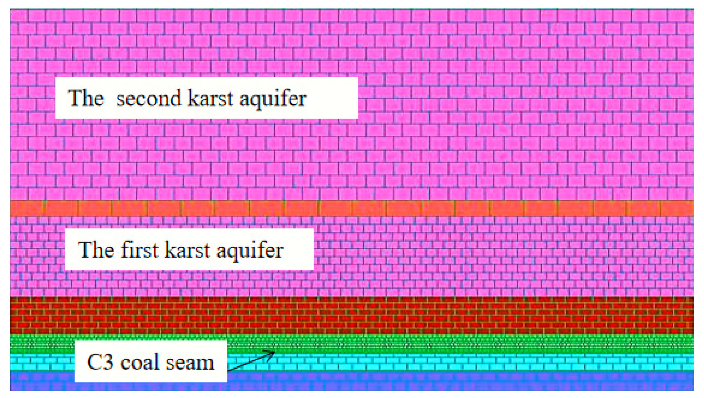
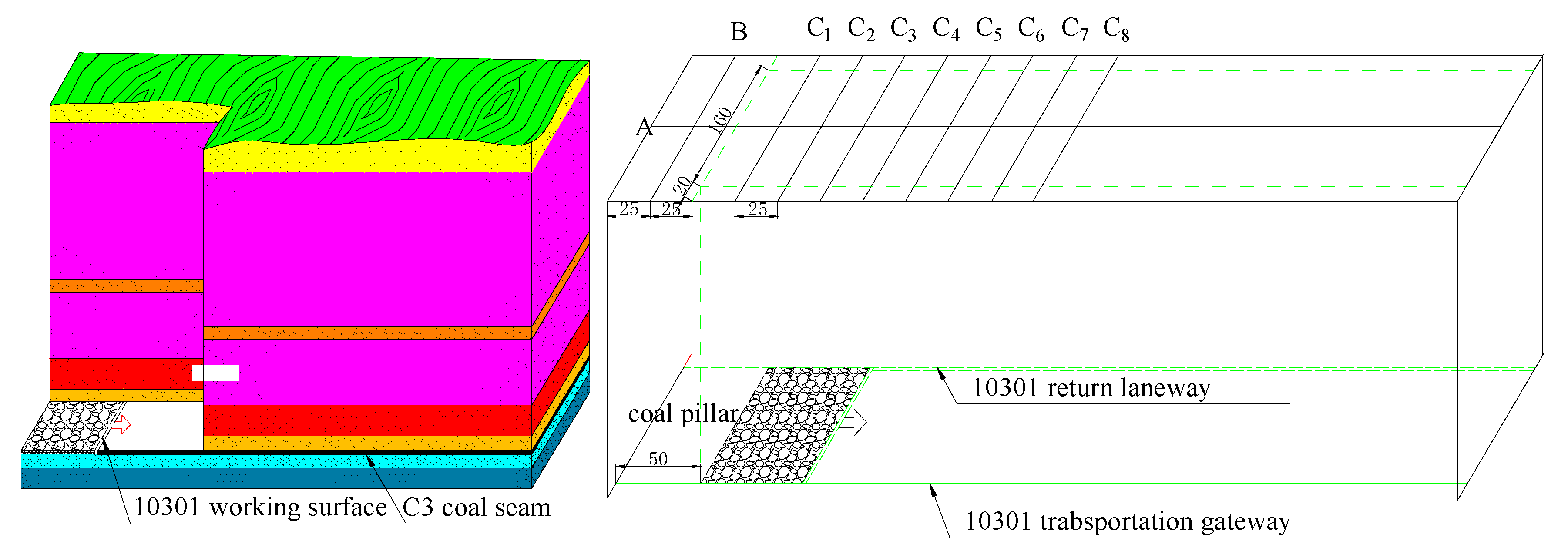
2.1. Engineering Background

The Daojiao coal mine is located in Songkan Town, Tongzi County, Guizhou Province with geographical coordinates 106°53′49″–106°54′25″ E and 28°30′14″–28°31′32″ E. The designed production capacity of the technical transformation of the mine was 300,000 t/A. C3 as the main coal seam in the Daojiao coal mine was located in the middle and upper part of Longtan Formation, about 26 m away from the limestone of Maokou Formation, and the thickness of the coal seam was in the range of 1.86 to 2.26 m with an average thickness of 2.02 m. In addition, the dip angle and the average buried depth were 7° and 210 m, respectively. The 10,301 working faces were laid out in this main coal seam, and the length, mining height and advancing length were 160 m, 2.02 m and 540 m, respectively. Moreover, the roof lithology in the 10,301 working faces was mudstone, carbonaceous mudstone and locally intercalated siltstone, while the floor lithology was clay rock and mudstone as shown in Figure 1. The main aquifers and impermeable stratum in the mining area were Quaternary (Q) pore aquifer, impermeable stratum of Triassic system (T1y3, T1y1), aquifers of Triassic system (T1y2), impermeable stratum of Permian (P3l) and aquifers of Permian (P3c, P3c).

2.2. Model Establishment and Parameters Selection

By taking 10,301 working faces of the Daojiao coal mine in Guizhou province as the engineering background, numerical simulation models using fluid-solid coupling with the length and height of 500 m × 240 m, respectively, were established to illustrate the influence of coal mining on the overlying strata movement and surface subsidence while both considering karst aquifer and not, as shown in Figure 2. In this study, the Mohr–Coulomb theory was adopted as the failure yield criterion and the contact Coulomb slip model was selected for the structural plane. Moreover, the upper part of the model was the free boundary and the lower part of the model was restrained vertically with lateral constraints on the left and right boundaries. In terms of overlying strata containing two extremely thick karst aquifers, a smaller block in these layers was set because its integrity and strength were porous. In addition, there was an impermeable stratum of mudstone between the two karst aquifers with good integrity and high strength to set as the larger block, and the block size of other overlying strata gradually increased with the distance away from coal seam. Moreover, the 50 m coal pillars were reserved on the left and right to eliminate the boundary effect with the working face total advancing 400 m.
According to the field-monitoring hydrogeological data from the coal mine, the average buried depth of the static water level in the mining area was 10 m, and there was a certain hydraulic connection between the two aquifers. Therefore, a water head pressure of 1.8 MPa varying in gradient along the gravity direction was applied at the bottom of the first karst aquifer, and the left and right lower boundaries were set as impervious boundaries. The flow steady was set for seepage calculation. For comparing the influence of water drainage in the karst aquifer on the overlying strata movement and surface subsidence, a reference numerical simulation model of a karst aquifer without water was also established while keeping the other conditions constant, and the monitoring line was set along the strike on the surface with 30 points to analyze the overlying strata movement and surface subsidence. Table 1 illustrates the physical, mechanical and hydraulic parameters of each overlying strata layer.

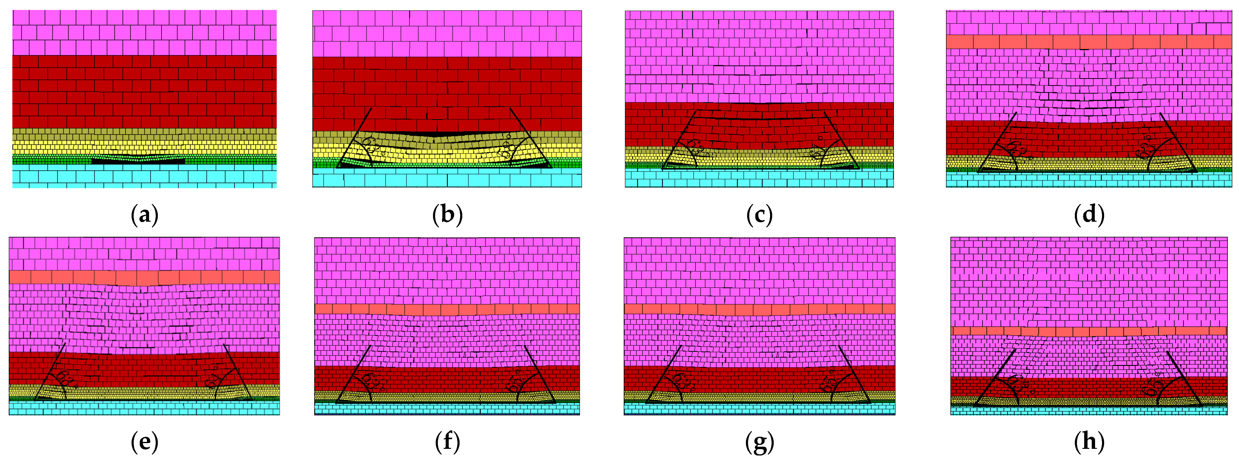
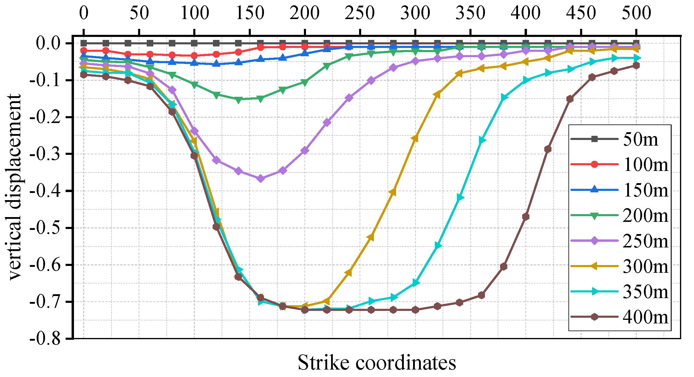
2.3. Overlying Strata Movement under the Condition of Karst Aquifer without Water

With the advance of the working face, the overlying strata movement and surface subsidence for the karst aquifer without water in the model are illustrated in Figure 3. When the advance of working face was 50 m, the immediate roof was suspended firstly under the action of self-weight stress, and the separation of strata or even collapses could be observed in the middle part of the overlying strata. With the working face advancing to 100 m, the overlying strata began to move, separate and sink due to the varying physical and mechanical properties of each rock layer, and the rock stratum in the middle of the goaf was collapsed and compacted. In addition, there was a large separation in the rock strata above the middle. With the continuous advancing of the working face as shown in Figure 3c–h, the caving strata in the middle of the goaf was continuously compacted, and large separation fractures appeared in the overlying strata near the open cut and the working face. The cantilever structure of the overlying strata was formed at the open cut and working face due to the support of the coal wall. Therefore, a similar triangular area could be observed between the open cut and the working face. Generally, the overlying strata undergo the processes of deformation, separation and collapse with the generation of three zones in the horizontal and vertical directions.
Table 2 illustrates the front and rear collapse angles of the overlying strata with the different advance distances. It can be observed that the rear collapse angle of the overlying strata stayed constant at 63°, and that the front collapse angle of the overlying strata increased with the increase in advancing distance at first, and then kept stable at 65° after advancing 300 m. In addition, the front collapse angle of the overlying strata was equal to the rear collapse angle when the advance distance of the working face was 200 m.
Figure 4 illustrates the surface vertical displacement with the increase in advancing distance of the working face for the karst aquifer without water. It can be observed that the surface subsidence caused by coal mining was relatively small (<0.06 m) until the working face advanced to 150 m. When the advancing distance of the working face was 200 m, the surface subsidence in the middle of the goaf was greater than that of both sides, and the growth rate of the maximum surface subsidence increased significantly until the advancing distance of the working face increased to 300 m. Correspondingly, the maximum surface subsidence reached to 0.62 m. And the maximum point of surface subsidence was close to the middle of goaf. In addition, the surface-subsidence curve was symmetrical with the center of the overlying strata in the goaf. Moreover, the surface subsidence above the open cut was always greater than that of above the working face in the whole advancing process of the working face.
In terms of the vertical displacement of different overlying strata layers, the curves were generally symmetrically distributed as shown in Figure 5, and the vertical displacement of the overlying strata in the goaf decreased with the increase in the distance away from the coal seam, while the vertical displacement of the overlying strata above the open cut and the coal wall slightly increased with the increase in the distance away from the coal seam. To be specific, the maximum vertical displacement of the overlying strata away from coal seam with 10 m, 34 m and 84 m was 1.79 m, 1.65 m and 0.94 m, respectively.

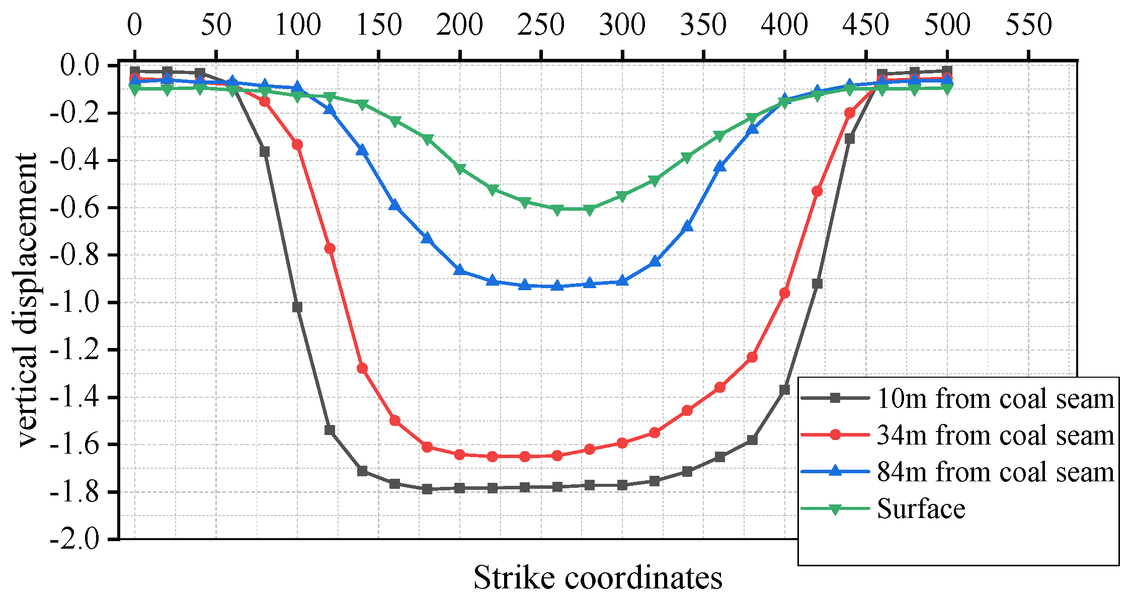
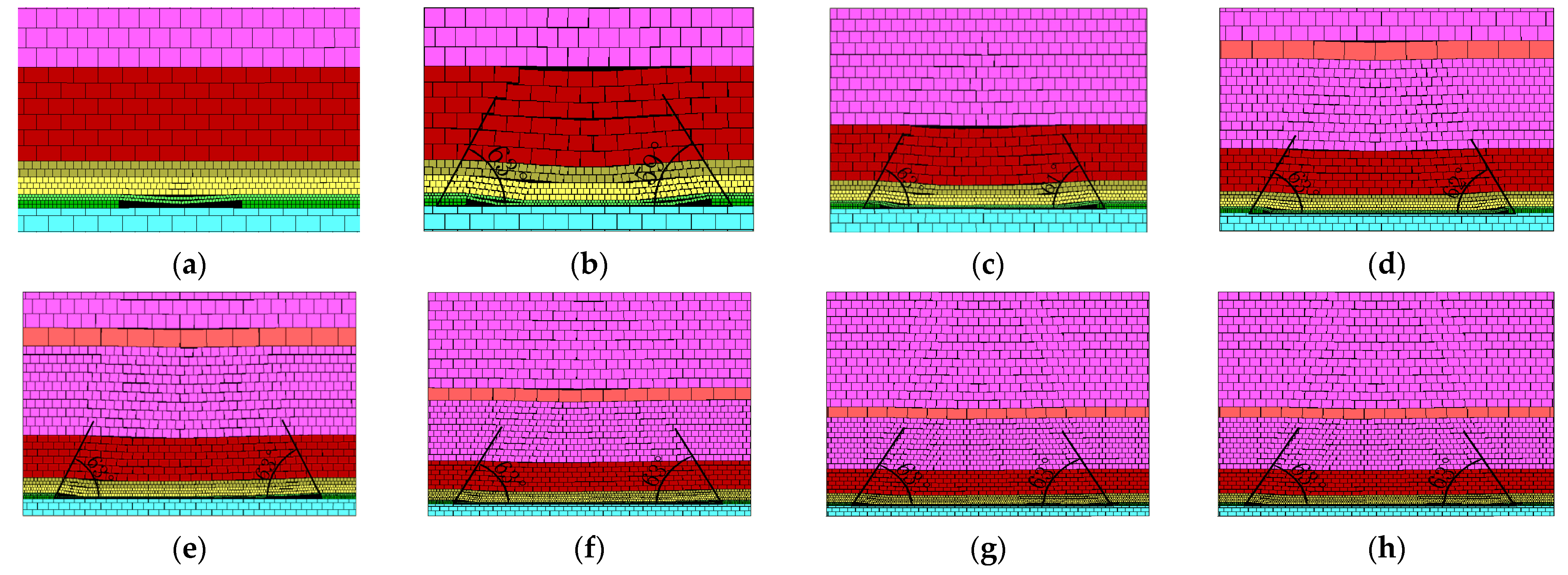
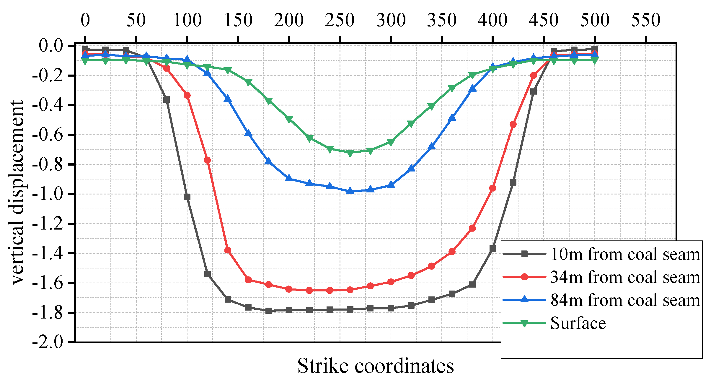
2.4. Overlying Strata Movement under the Condition of Karst Aquifer with Water

Figure 6 illustrates the overlying strata movement for the karst aquifer with water. The separation and collapse of the overlying strata could be firstly observed in the middle position when the advance distance of the working face was 50 m, and a further large separation between the sandy mudstone and the bottom of the first karst aquifer was revealed due to the influence of mining stress and aquifer seepage when the advance distance of the working face was 100 m. With the advance distance of the working face increasing to 150 m, the separation range between the sandy mudstone and the bottom of the first karst aquifer continued to expand, and then this separation was compacted when the advance distance of working face was 200 m, which could not be observed in the overlying strata movement for the karst aquifer without water. Meanwhile, a large separation between the bottom of the second karst aquifer and the mudstone was generated. With the continuous advancing of the working face, the separated strata were gradually compacted again.
Table 3 illustrates the collapse angle of the overlying strata for the karst aquifer with water. Similarly, the rear collapse angle was still 63°, while the front collapse angle increased at first and then kept constant with the increase in the workface advancing, and the front collapse angle was equal to the rear collapse when the advance distance of the working face was 250 m. Generally, the overburden collapse angle in this condition was roughly the same for the karst aquifer without water under each advancing distance of the working face.
Figure 7 illustrates the surface vertical displacement with the increase in advancing distance of the working face for the karst aquifer with water. It can be observed that the surface subsidence caused by coal mining was relatively small (<0.07 m) until the working face advanced to 150 m. When the advancing distance of the working face was 200 m, the surface subsidence in the middle of the goaf was greater than that of both sides, and the growth rate of the maximum surface subsidence increased significantly until the advancing distance of the working face increased to 300 m. Correspondingly, the maximum surface subsidence reached 0.72 m, which was greater than that of the karst aquifer without water.
In terms of the vertical displacement of the different overlying strata layers for the karst aquifer with water, the curves were generally symmetrically distributed as shown in Figure 8, and the vertical displacement of the overlying strata in the goaf decreased with the increase in the distance away from the coal seam, while the vertical displacement of the overlying strata above the open cut and the coal wall slightly increased with the increase in the distance away from the coal seam. Compared with the condition of the karst aquifer without water, the vertical displacement in the different rock layers for the karst aquifer increased. To be specific, the maximum vertical displacement of the overlying strata away from coal seam with 10 m, 34 m and 84 m was 1.87 m, 1.74 m and 1.2 m, respectively.
As shown in Figure 9, the surface subsidence for the karst aquifer with water was greater than the karst aquifer without water. To be specific, the maximum vertical displacement was 0.62 and the subsidence coefficient was 0.305 in the condition of the karst aquifer without water, while the corresponding values were 0.72 m and 0.35, respectively, for the karst aquifer with water. This can be explained by the fact that the water in the karst aquifer flowed to the working face along the fracture with the advance of the working face because the fracture in the rock strata was connected to the karst aquifer. In addition, the drainage of the working face led to a decrease in osmotic pressure of the karst aquifer and the increase in the effective stress of the fractured limestone.

3. Theory Model of Surface Subsidence under the Condition of Karst Aquifer with Water

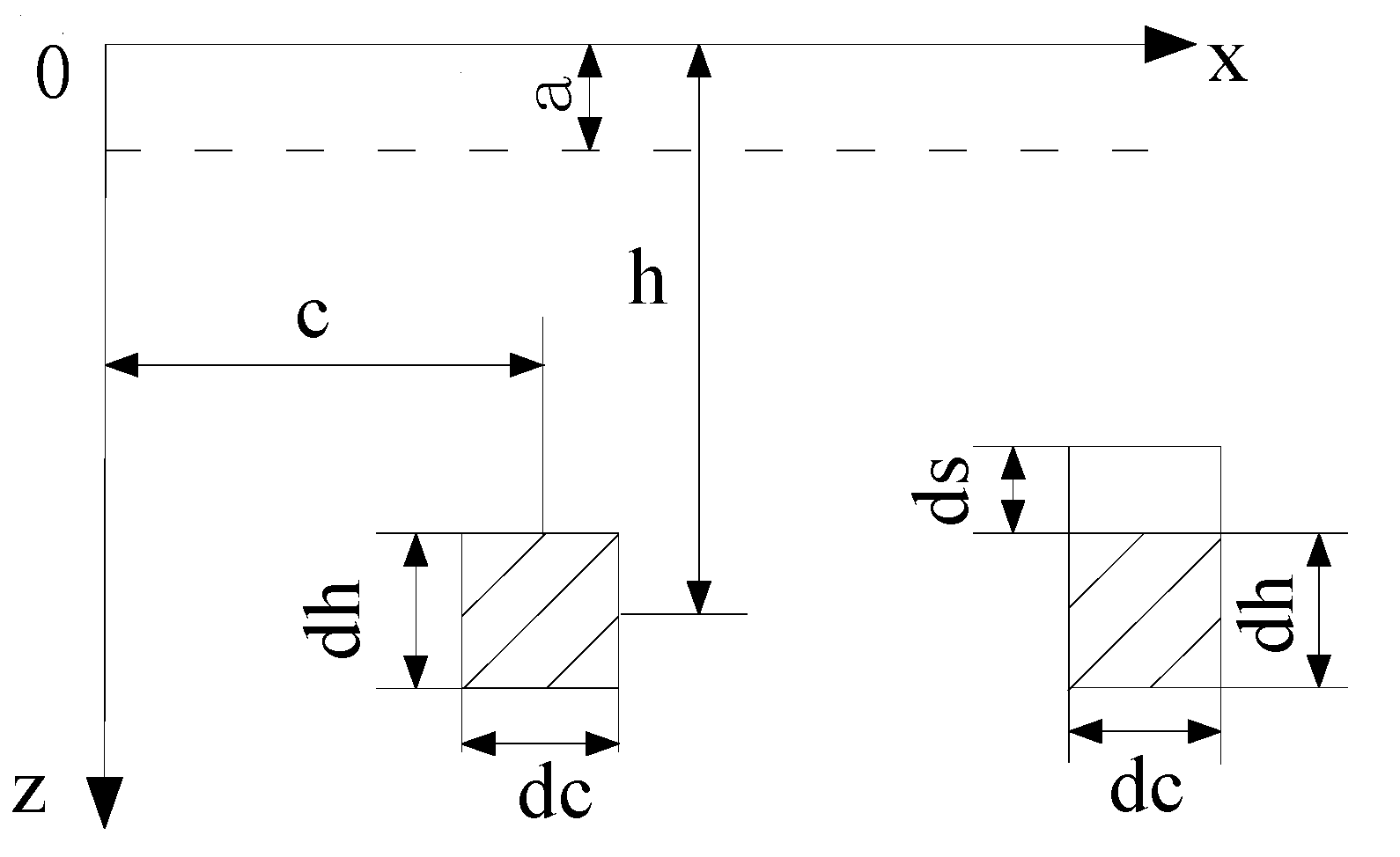
3.1. Calculation Model of Surface Subsidence Caused by Aquifer Drainage

When considering the consolidation drainage of a soil aquifer, the compression deformation is usually calculated by formula (1) [28]. The corresponding principle of effective stress can produce an increment of Δp when the pore-water pressure in the soil decreases Δp and the axial deformation of limestone aquifer (εz) is related to various factors such as osmotic pressure drop (Δp), initial seepage pressure (p0), confining pressure (σ3) and other factors in the calculation of drainage deformation of the karst aquifer. However, the osmotic pressure in the fractured limestone can decrease Δp, and the stress increment is different due to the difference in initial osmotic pressure (p0) and confining pressure (σ3), which did not agree with the principle of effective stress. Therefore, the principle effective stress modified by the Biot coefficient αb can be used in the calculation of consolidation-drainage deformation of the karst aquifer, and Equation (1) can be changed to Equation (2).
ε z = a v Δ p 1 + e 0
ε z = α b a v Δ p 1 + e 0
where αb is the Biot coefficient; εz is the axial displacement deformation; av is the compressibility coefficient of rock and soil mass; e0 is the initial void ratio of rock and soil mass; Δp is the pore pressure.
According to the characteristics of aquifer drainage, the consolidation-drainage-deformation model of the karst aquifer was established as shown in Figure 10.
a” was set as the buried depth of the groundwater level before aquifer drainage. If the rock mass below z = a was saturated, the element stress of plane “dcdh” at depth h can be expressed as follows
σ = a γ s + ( h a ) γ s a t
where γs is the volume weight of rock mass above the groundwater level; γsat is the volume weight of saturated rock mass.
Pore-water pressure can be expressed as follows
p w = ( h a ) γ w
where γw is the volume weight of pore water.
The particle stress of rock mass skeleton can be expressed as follows
σ s = σ p w = a γ s + ( h a ) ( γ s a t γ w )
The pore-water pressure caused by the drainage of aquifer will be borne by the skeleton particles of the rock mass. According to the principle of effective stress modified by the Biot coefficient αb, the stress increment of the rock-mass skeleton particles can be expressed as follows
α b Δ p = α b ( h a ) γ w
According to Equation (2), the small compression deformation of element “dcdh” under the action of stress increment (αbΔp) can be expressed as follows
d s = α b a v Δ p 1 + e 0 d h = α b a v ( h a ) γ w 1 + e 0 d h
According to the random medium theory, after the drainage of rock mass, the movement of rock mass above the unit is dWwater(x) due to the small subsidence (ds) caused by the drainage of karst aquifer. Meanwhile, the movement of rock mass above the unit is dW(x) + dWwater(x) due to the micro subsidence (dh), where dW(x) is the micro unit of surface subsidence caused by the rock mass without considering drainage.
Therefore, the corresponding expression can be expressed as follows
d W w a t e r ( x ) = α b a v ( h a ) γ w 1 + e 0 × [ d W w a t e r ( x ) + d W ( x ) ]
According to the random medium theory, the surface forms a small unit subsidence basin. In the drainage water of rock and soil mass, any unit can produce slight compression, and the sinking formula of a water micro unit can be shown as follows
W w a t e r e l e m e n t ( x ) = 1 r w × exp [ π x 2 r w 2 ]
where rw is the main influence radius of surface subsidence caused by drainage.
According to the principle of superposition, the surface subsidence caused by aquifer drainage can be expressed as follows
W w a t e r ( x ) = 0 c W w a t e r e l e m e n t ( x ) d c
According to Equations (4)–(8), the formula can be obtained as follows
W w a t e r ( x ) = α b a v ( h a ) γ w 1 + e 0 α b a v ( h a ) γ w W ( x )
According to the literature, when the drainage of rock mass is not considered and the mining width of the coal seam is “c”, the surface subsidence can be expressed as follows [28]
W ( x ) = 0 c W 0 r exp [ π ( x c ) 2 r 2 ] d c ,   W 0 = m q cos α
where W0 is the maximum surface subsidence, r is the main influence radius of surface subsidence, m is the mining height, and α is the dip angle of coal seam.
Using the probability integral function erf, Equation (12) can be transformed into the following formula.
W ( x ) = W 0 2 [ erf ( π r x ) + 1 ]
where erf is the probability integral function, erf [ π r ] = 2 π 0 π r x exp ( u 2 ) d u . The probability integral function can be obtained by looking up the probability integral table.
By substituting Equation (13) into Equation (11), the following formula can be obtained.
W w a t e r ( x ) = W 0 α b a v ( h a ) γ w 2 [ ( 1 + e 0 ) α b a v ( h a ) γ w ] × [ erf ( π r x ) + 1 ]
It can also be expressed as follows
W w a t e r ( x ) = W 0 α b Δ e 2 [ ( 1 + e 0 ) α b Δ e ] × [ erf ( π r x ) + 1 ]
The change of the geotechnical void ratio can be expressed as follows
Δ e = a v ( h a ) γ w
And the surface subsidence caused by underground mining and aquifer drainage can be expressed as follows
W ( x ) = W w a t e r ( x ) + W ( x )
where W′(x) is the surface subsidence caused by underground mining and aquifer drainage, W(x) is the surface subsidence caused by mining obtained by probability integral method.

3.2. Theoretical Calculation

According to the above numerical-simulation results, due to the influence of mining, the water flow in the overlying aquifer was recharged downward to the lower aquifer as shown in Figure 11, and there was a hydraulic connection among the three rock strata.
However, with the advancement of workface mining, the following processes can change in turn:
When the water-conducting fissure zone extended to the first karst aquifer, the first karst aquifer was drained. There was a head difference between the first karst aquifer and the second karst aquifer. When the initial seepage gradient of the rock and soil strata was reached, the overflow from phreatic water to confined water could be observed.
With the expansion of the water flow seepage to the impermeable mudstone, the overall permeability of the impermeable mudstone increased. The second karst aquifer replenished the first karst aquifer through the impermeable mudstone, and the water volume increased. The amount of water supplemented by the second karst aquifer to the first karst aquifer through the impermeable mudstone increased as well.
When the overall water impermeability of the mudstone stratum reduced to a certain value, the first and second karst aquifers could connect with each other and the drawdown of the water level increased with the increase in the thickness of aquifer, which intensifies the surface subsidence value caused by the consolidation-drainage deformation of aquifer. Therefore, the two overlying karst aquifers can be regarded as one aquifer for calculation.
According to field data in the Daojiao coal mine, without considering the drainage of aquifer, the calculation parameters of surface subsidence after coal mining can be expressed as follows.
The coefficient of mining subsidence: q = 0.305.
The main influence tangent angle:
tan β = 2 π tan ( 45 ° 0.5 φ ) 2.5 = 0.58
where φ is the internal friction angle (30°).
The main influence radius of surface subsidence after C3 coal-seam mining.
r = H/tanβ = 180/2.25 = 310 m
The maximum surface subsidence: W0 = 2.02 × 0.305 × cos7° = 0.6 m.
When considering the consolidation-drainage of aquifer, the values of various parameters were expressed as follows: x = 400 m, a = 10 m, h = 10–180 m, e0 = 0.23, Δe = 0.21, αb = 0.95.
By substituting the above data into Equation (15), the expression can be obtained.
Δ e = a v ( h a ) γ w , W w a t e r ( 400 ) = 0.6 × 0.95 × 0.26 2 [ ( 1 + 0.29 ) 0.95 × 0.26 ] × [ erf ( π 310 × 400 ) + 1 ] = 0.13 m
The maximum value of surface subsidence caused by underground mining and aquifer drainage can be expressed as follows: W′max = Wwater(x) + W0 = 0.73 m.
According to the calculation results, the surface subsidence caused by aquifer drainage accounted for 17.8% of the total surface subsidence, indicating that the increment of surface subsidence caused by multi-aquifer drainage cannot be ignored.

4. Engineering Measurement and Analysis

4.1. Observation Scheme

Laser-tracking technology has the advantages of a high measurement accuracy and efficiency, and it is widely used in mine-surface measurement. Therefore, laser-tracking technology was used to observe the surface subsidence with the advance of the 10,301 working faces in the Daojiao coal mine. In order to reduce the impact of temperature fluctuation on the observation results, the observation points arranged on the surface were buried 300 mm below the topsoil. The observation data adopted the national standard of the third-class vertical control point as the reference point in order to ensure the accuracy of the observation results. Figure 12 illustrates the arrangement of surface-observation stations in the 10,301working faces. An observation line was designed along the trend of the working face with a length of 500 m (baseline A) and an observation point was arranged every 20 m on this line (total 26 observation points). In addition, a total of nine observation lines were arranged along the inclination of the working face with a length of 200 m and observation points arranged every 20 m on these lines. Specifically, observation line B was located above the coal pillar and away from the boundary by 25 m, and observation lines C1 to C8 were located above the goaf and away from open cut by 25 m, 50 m, 75 m, 100 m, 125 m, 150 m, 175 m and 200 m, respectively.

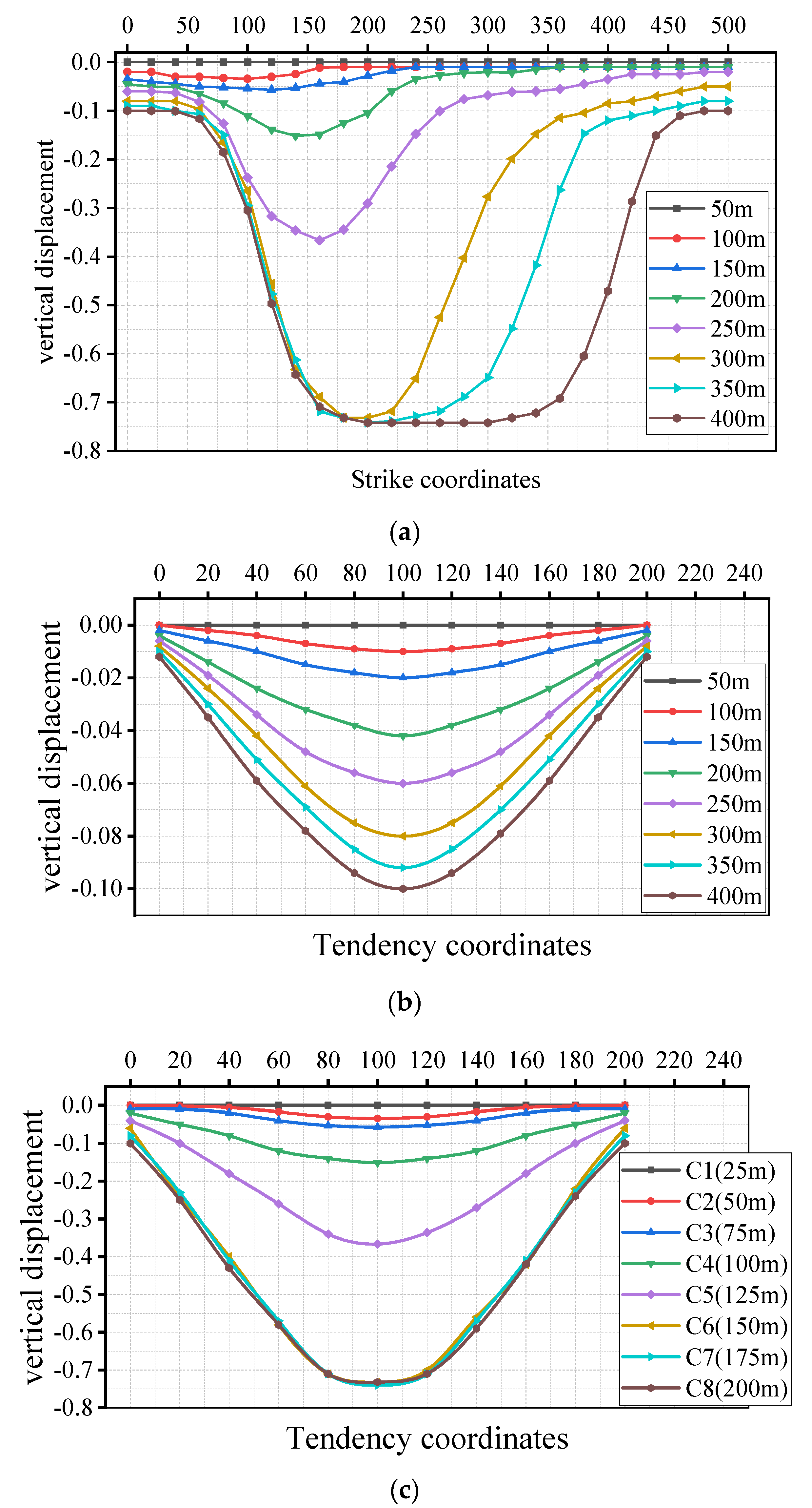
4.2. Results and Analysis

The laser-tracking technology was used to observe the surface subsidence during the whole mining period (about one month), and total data records were compiled for each measuring point. Figure 13 illustrates the surface-subsidence curves in the trend and inclination directions of the 10,301 working faces. With the continuous advancement of the working face, the maximum value of the surface subsidence gradually moved to the central position of the goaf, and the surface subsidence increased with the increase in workface advancement until the workface had advanced to 300 m. The maximum surface subsidence was 0.74 m and the subsidence curve was symmetrical with the middle of the goaf as the center. In addition, the surface subsidence near the open cut was always greater than that near the working face. This can be explained by the fact that the affected range of surfaces in the mining process became larger with the advancement of the workface and the cracks caused by mining were gradually compacted due to the collapsed rock filling in the goaf as the roof support. Moreover, the consolidation-drainage of aquifer near the open cut was greater than that near the working face, and the stress originally borne by pore water was transferred to the rock mass to increase the effective stress, which caused the consolidation of rock and the surface subsidence. It can be illustrated that the surface subsidence for the karst aquifer with water was the joint action of coal-seam mining and aquifer drainage.

5. Discussion

Based on the numerical simulation and theory analysis, the maximum surface subsidence of the mining area for the karst aquifer without water drainage was 0.62 m and 0.6 m, respectively, and the maximum surface subsidence of the mining area with considering water drainage was 0.72 m and 0.73 m, respectively, which was consistent with the field monitoring result of 0.74 m. It verified the results and the accuracy of the numerical simulation and theoretical calculation. The proposed theory model in this study was based on the effective stress principle modified by the Biot coefficient αb and can effectively and accurately obtain the surface subsidence while considering water drainage in a karst aquifer and also provide great help in understanding karst topography.
However, there were also some limitations in illustrating the surface subsidence and the overlying strata movement with respect to the water drainage of aquifer. Specifically, the hydrogeological conditions were simplified in the numerical simulation. However, the lithology and hydrogeological conditions of the overlying strata were complex and changeable in the process of real mining environment. In addition, the drainage tests of aquifer rock samples can be further performed to analyze the relationship between axial deformation and the relevant factors (e.g., pore pressure drop Δp, initial seepage pressure p0 and confining pressure σ3). Moreover, more than two observation lines can be laid out along the strike of workface to improve the accuracy of the observation results under the condition of economic rationality.

6. Conclusions

In this study, by taking 10,301 working faces of the Daojiao coal mine in Guizhou Province as the engineering background, comprehensive research methods (e.g., numerical simulation, theory analysis, field monitoring) were adopted in order to illustrate the laws of overlying strata movement and the mechanism of surface subsidence with/without considering water drainage in multi-karst aquifers. The main conclusions are as follows:
(1)
Compared with the karst aquifers without water, the movement and deformation characteristics of overburden for the karst aquifers with water drainage were quite different, while the collapse angle of overburden was roughly the same.
(2)
With the advance of the workface, the fracture caused by mining activities can penetrate to a karst aquifer and the water in the aquifer can flow to the workface along the fracture. The water drainage can decrease the osmotic pressure of aquifer, increase the effective stress of fractured limestone and the compression of aquifer, which can intensify the surface subsidence.
(3)
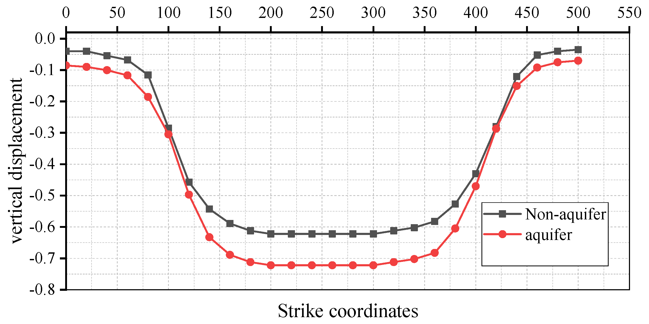
The maximum surface subsidence of mining area for the karst aquifer without water drainage was about 0.6 m, and the maximum surface subsidence of the mining area when considering water drainage was about 0.73 m. Therefore, the surface subsidence caused by drainage of multi-aquifer accounted for 17.8% of the total surface subsidence.
(4)
Based on the effective stress principle modified by the Biot coefficient αb, the axial deformation of aquifer with considering water drainage can be obtained, and the field-monitoring results of surface subsidence can also verify the accuracy of the theory-model results.

Author Contributions

Y.W.: Formal analysis, Numerical simulation, Experimental test, Writing-Original draft; G.W.: Data curation, Methodology, Writing-Original draft, Numerical Simulation, Experimental test, Funding acquisition; Y.L.: Formal analysis, Investigation; Z.C.: Formal analysis, Methodology, Validation, Writing-Review and editing. All authors have read and agreed to the published version of the manuscript.

Funding

This study is supported by the Guizhou Science and Technology Plan Project (Qianke Science Foundation ((2020) 1Y214, (2021) General 399), the National Natural Science Foundation of China Regional Fund (No. 52164005, No. 52064005, No. 52164002), the National Natural Science Foundation of China Youth Fund (No. 51904082).

Institutional Review Board Statement

Not applicable.

Informed Consent Statement

Not applicable.

Data Availability Statement

All data used during the study appear in the submitted article.

Conflicts of Interest

The authors declare no conflict of interest.

References

  1. Verma, A.; Mandal, S.K.; Singh, P.K. Trait of subsidence under high rate of coal extraction by longwall mining: Some inferences. Sadhana-Acad. Proc. Eng. Sci. 2021, 46, 216. [Google Scholar] [CrossRef]
  2. Qiang, Z.; Zhang, J.X.; Feng, J. Backfilling technology and strata behaviors in fully mechanized coal mining working face. Int. J. Min. Sci. Technol. 2012, 22, 151–157. [Google Scholar] [CrossRef]
  3. Xiong, Y.; Kong, D.; Cheng, Z.; Wu, G.; Zhang, Q. The Comprehensive Identification of Roof Risk in a Fully Mechanized Working Face Using the Cloud Model. Mathematics 2021, 9, 2072. [Google Scholar] [CrossRef]
  4. Lv, H.; Cheng, Z.; Dong, Y.; Zhang, J.; Ma, Y. Numerical simulation on the crack initiation and propagation of coal with combined defects. Struct. Eng. Mech. 2021, 79, 237–245. [Google Scholar] [CrossRef]
  5. Lv, H.; Cheng, Z.; Liu, F. Study on the mechanism of a new fully mechanical mining method for extremely thick coal seam. Int. J. Rock Mech. Min. Sci. 2021, 142, 104788. [Google Scholar] [CrossRef]
  6. Han, C.L.; Zhang, N.; Yang, H.Q. Superposed disturbance mechanism of sequential overlying strata collapse for gob-side entry retaining and corresponding control strategies. J. Cent. South Univ. 2018, 25, 2258–2271. [Google Scholar] [CrossRef]
  7. Liang, Q.H. Study of Numerical Simulation and Application on Thick-Alluvium Surface Subsidence. Ph.D. Thesis, Shandong University of Science and Technology, Qingdao, China, 2006. [Google Scholar]
  8. Xu, J.L.; Lian, G.M.; Zhu, W.B. Influence of the key strata in deep mining to mining subsidence. J. China Coal Soc. 2007, 32, 686–690. [Google Scholar]
  9. Singh, R.; Mandal, P.K.; Singh, A.K. Upshot of strata movement during underground mining of a thick coal seam below hilly terrain. Int. J. Rock Mech. Min. 2007, 45, 29–46. [Google Scholar] [CrossRef]
  10. Ramesh, P.S.; Ram, N.Y. Subsidence prediction method based on equivalent mining height theory for solid backfilling mining. Trans. Nonferr. Met. Soc. 2014, 24, 3302–3308. [Google Scholar] [CrossRef]
  11. Qin, Y.; Xue, J.Q.; Chen, B.Q. A model for extracting large deformation mining subsidence using D-InSAR technique and probability integral method. Trans. Nonferr. Met. Soc. 2014, 24, 1242–1247. [Google Scholar] [CrossRef]
  12. Ge, L.L.; Guo, J.T.; Ng, A.H.M. Numerical simulation of dynamic surface deformation based on DInSAR monitoring. Trans. Nonferr. Met. Soc. 2014, 24, 1248–1254. [Google Scholar] [CrossRef]
  13. Feng, W.P.; Xu, L.S. Fault parameters of the October 2008 Damxung M(w)6.3 earthquake from InSAR inversion and its tectonic implication. Chin. J. Geophys. 2010, 53, 1134–1142. [Google Scholar] [CrossRef]
  14. Soni, A.K.; K Singh, K.K.; Prakash, A.; Singh, K.B.; Chakraboraty, A.K. Shallow cover over coal mining: A case study of subsidence at Kamptee Colliery, Nagpur India. Bull. Eng. Geol. Environ. 2007, 66, 311–318. [Google Scholar] [CrossRef]
  15. Liu, X.L. Study on the Law of Dewater Settlement of Bottom Aquifer in Overburden. Ph.D. Thesis, China University of Mining and Technology, Beijing, China, 2000. [Google Scholar]
  16. Zhang, D.S.; Fan, G.W.; Ma, L.Q.; Wang, X.F. Aquifer protection during longwall mining of shallow coal seams: A case study in the Shendong Coalfield of China. Int. J. Coal Geol. 2011, 86, 190–196. [Google Scholar] [CrossRef]
  17. Ma, R.Z. Research the Law of Surface Movement and Deformation of Multiple Mining under Confined Water Loss and Thick Unconsolidated Layers. Ph.D. Thesis, Anhui University of Science & Technology, Huainan, China, 2014. [Google Scholar]
  18. Li, Y.; Peng, S.S.; Zhang, J.W. Impact of longwall mining on groundwater above the longwall panel in shallow coal seams. Int. J. Min. Reclam. Env. 2016, 30, 295–311. [Google Scholar] [CrossRef]
  19. Nie, L.; Wang, H.F.; Xu, Y. Application of the arctangent function model in the prediction of ground mining subsidence deformation: A case study from Fushun City, Liaoning Province, China. B Eng. Geol. Environ. 2017, 76, 1383–1398. [Google Scholar] [CrossRef]
  20. Kong, D.; Cheng, Z.; Zheng, S. Study on the failure mechanism and stability control measures in a large-cutting-height coal mining face with a deep-buried seam. Bull. Eng. Geol. Environ. 2019, 78, 6143–6157. [Google Scholar] [CrossRef]
  21. Cheng, Z.; Li, L.; Zhang, Y. Laboratory investigation of the mechanical properties of coal-rock combined body. Bull. Eng. Geol. Environ. 2020, 79, 1947–1958. [Google Scholar] [CrossRef]
  22. Kong, D.; Pu, S.; Cheng, Z.; Wu, G.; Liu, Y. Coordinated Deformation Mechanism of the Top Coal and Filling Body of Gob-Side Entry Retaining in a Fully Mechanized Caving Face. Int. J. Geomech. 2021, 21, 04021030. [Google Scholar] [CrossRef]
  23. Kong, D.; Xiong, Y.; Cheng, Z.; Wang, N.; Wu, G.; Liu, Y. Stability analysis of coal face based on coal face-support-roof system in steeply inclined coal seam. Geomech. Eng. 2021, 25, 233–243. [Google Scholar] [CrossRef]
  24. Cheng, Z.; Yang, S.; Li, L.; Zhang, L. Support working resistance determined on top-coal caving face based on coal-rock combined body. Geomech. Eng. 2019, 19, 255–268. [Google Scholar] [CrossRef]
  25. Lv, H.; Tang, Y.; Zhang, L.; Cheng, Z.; Zhang, Y. Analysis for mechanical characteristics and failure models of coal specimens with non-penetrating single crack. Geomech. Eng. 2019, 17, 355–365. [Google Scholar] [CrossRef]
  26. Lou, J.; Gao, F.; Yang, J.; Ren, Y.; Li, J.; Wang, X.; Yang, L. Characteristics of evolution of mining-induced stress field in the longwall panel: Insights from physical modeling. Int. J. Coal Sci. Technol. 2021, 8, 938–955. [Google Scholar] [CrossRef]
  27. Cheng, Z.; Pan, W.; Li, X.; Sun, W. Numerical simulation on strata behaviours of TCCWF influenced by coal-rock combined body. Geomech. Eng. 2019, 19, 269–282. [Google Scholar] [CrossRef]
  28. He, G.Q.; Yang, L.; Ling, G.D. Mining Subsidence Science; China University of Mining and Technology Press: Xuzhou, China, 1991. [Google Scholar]
Figure 1. Comprehensive stratigraphic column map.
Mathematics 10 00169 g001
Figure 2. UDEC numerical model.
Mathematics 10 00169 g002
Figure 3. Overlying strata movement with the different advance distance of working face. (a) Working face advance 50 m. (b) Working face advance 100 m. (c) Working face advance 150 m. (d) Working face advance 200 m. (e) Working face advance 250 m. (f) Working face advance 300 m. (g) Working face advance 350 m. (h) Working face advance 400 m.
Mathematics 10 00169 g003
Figure 4. Surface vertical displacement for the karst aquifer without water.
Mathematics 10 00169 g004
Figure 5. Vertical displacement of different overlying strata layers.
Mathematics 10 00169 g005
Figure 6. The movement and deformation of mining strata under multi-aquifer. (a) Working face advance 50 m. (b) Working face advance 100 m. (c) Working face advance 150 m. (d) Working face advance 200 m. (e) Working face advance 250 m. (f) Working face advance 300 m. (g) Working face advance 350 m. (h) Working face advance 400 m.
Mathematics 10 00169 g006
Figure 7. Surface vertical displacement for the karst aquifer with water.
Mathematics 10 00169 g007
Figure 8. Vertical displacement of different overlying strata layers for the karst aquifer with water.
Mathematics 10 00169 g008
Figure 9. Comparison of surface vertical displacement.
Mathematics 10 00169 g009
Figure 10. Consolidation-drainage-deformation model of karst aquifer.
Mathematics 10 00169 g010
Figure 11. Leakage recharge model of multi-aquifer in Daojiao coal mine.
Mathematics 10 00169 g011
Figure 12. Layout of surface observation lines.
Mathematics 10 00169 g012
Figure 13. Curve of surface subsidence with the advance of working face. (a) Observation line A. (b) Observation line B. (c) Observation line C.
Mathematics 10 00169 g013
Table 1. Physical, mechanical and hydraulic parameters of coal and rock mass.
Rock TypeThickness
(m)
Density
(kg/m3)
Bulk
/(GPa)
Shear
/(GPa)
Internal Friction Angle
/(°)
Cohesion
/(MPa)
Tensile Strength
/(MPa)
Permeability Coefficient
/(pa−1s−1)
Initial Gap Width
/(mm)
Residual Gap Width
/(mm)
Limestone110 m28005.574.533811.46.71100.20.05
Mudstone10 m27002.861.4392.82.48830.010.005
Changxing Limestone50 m243011.18.3352.44.41100.20.05
Sandy mudstone24 m225010.26.1301.83.2830.010.005
Mudstone4 m25505.83.2301.23.25830.010.005
Sandy mudstone4.5 m225010.26.1301.83.2830.010.005
Carbon mudstone1.5 m24503.22.8300.71.8830.010.005
C3 Coal2 m14701.190.82251.31.79830.010.005
Tonstein10 m22503.292.27274.93.8830.010.005
C1 Coal1 m14701.190.82251.31.79830.010.005
Mudstone13 m25505.83.2301.23.25830.010.005
Water-1000--------
Table 2. Summary of overlying strata caving angles with different advance distances.
Advancing Distance of Working Face/mFront Collapse Angle/°Rear Collapse Angle/°
1005863
1506163
2006363
2506463
3006563
3506563
4006563
Table 3. Overlying strata caving angles with different advance distances under multi-aquifer.
Advancing Distance of Working Face/mFront Collapse Angle/°Rear Collapse Angle/°
1005963
1506163
2006263
2506363
3006363
3506363
Publisher’s Note: MDPI stays neutral with regard to jurisdictional claims in published maps and institutional affiliations.

