Abstract
In this paper, an optimization algorithm is proposed for the system, where a decode-and-forward (DaF) protocol based full duplex relay (FDR) and an intelligent reflecting surface (IRS) work together to deliver message signals from a source to a destination. The transmission is carried out in a single time frame due to the full duplex nature of the FDR and IRS. The joint optimization of the beamformers for the multiple antenna sets at the source along with the FDR antenna sets and the phase adjustment of the reflecting elements at the IRS is proposed. Though separate optimizations of the beamformers and the phase adjustment were available previously, the joint one is more challenging due to the increased number of signal paths and the impacts from these new paths. To accommodate conflicting requirements from different paths, the reflecting elements of the IRS are cleverly grouped into the corresponding number of sets, where the requirements are met separately through the optimizations of the phase values of the corresponding group. For the beamformer optimization, we parameterize the beamforming vectors, which results in two concave optimization problems for the source and for the FDR relay. These optimization sets are implemented in an alternating manner to reach a reasonable solution. Simulation results are provided to illustrate the impacts of the proposed algorithm in various implementation scenarios and parameter sets. These results identify the gains the proposed algorithm provides and the scenarios where these gains are expected.
Keywords:
intelligent reflecting surface; phase adjustment; full duplex relay; beamformer optimization MSC:
65K10
1. Introduction
The inherent limitation from additional transmission hops and the associated spectrum resources of the half-duplex relaying has long blocked the wide adoption of the relaying techniques in the cellular networks, and thus, the research on the full-duplex relaying (FDR) has worked on improving its spectrum efficiency [1,2,3,4]. In FDR, where the two-hop transmissions from and toward a relay are overlapped in a time slot to save the bandwidth, the removal of self-interference (SI) is the key technical challenge [5,6,7]. As the advantage of FDR relies heavily on the processing of SI, various approaches to suppress the SI has been taken, such as the interference subtraction in the analog domain [1,2] and digital signal processing, including the beamforming (BF) with multiple input multiple output (MIMO) antennae sets [5,8,9,10,11,12]. Joint approaches of the analog domain subtraction and digital BF prove to be promising in one-way relaying [6] and in two-way relaying [13,14] as well.
So far, multiple antenna techniques have been considered and applied in cellular standards as they improve the wireless transmission channels. Recently introduced massive MIMO systems with large numbers of antenna elements have extended the multiple antenna techniques further to the limits. The implementation cost and the complexity associated with massive MIMO systems can be eased by hybrid analog-and-digital BF techniques [15,16,17,18,19], where hardware-intensive RF chains are limited to a few channels for the digital BF and the outputs of them are sent to the analog BF arrays with phase shifters for a large number of antenna elements. Similarly, Intelligent Reflecting surface (IRS) [20,21,22,23,24,25,26] is devised and introduced to remove the shadow areas of wireless networks by forming artificial transmission paths between wireless communication devices. While massive MIMO antennas are installed at the access point (AP) or user terminals, the IRSs with large numbers of reflecting elements are intentionally installed around the wireless networks and reflect the coming signals to provide additional signal paths between the user terminals. While the role is similar to wireless relaying, IRS is attractive as it requires much more affordable signal processing and transmission power than those for the relay systems.
Reportedly, the IRS achieves very close performance to that of relay networks in improving the wireless links [27,28,29,30,31,32] when there are a large number of reflecting elements deployed at the IRS. This remarkable benefit comes at the expense of installing IRS devices around the networks with relatively light hardware resources and affordable power consumption. Transmission systems with channel acquisition training methods are presented in [33,34] and the application of IRS in the millimeter channel is considered in [35]. The IRS also supports multicasting systems as considered in [36,37]. The outage performance of IRS assisted multicasting system is presented with a random phase adjustment at the IRS is presented in [36]. An application to the multi-way communication system is considered in [38] and the application to the non-orthogonal multiple access (NOMA) is considered in [39,40,41]. Similar to the beamforming for the multi-antenna system, the adjustment of the phases of the reflecting elements is the key optimization for the IRS [20,21,22,33,34,42]. It is shown in [22] that the optimal phase adjustment of a single user link with an IRS is aligning all the phases of the paths through the IRS to the phase of the direct channel from the base station to the user. The outage performance of IRS assisted multicasting system is analyzed in [36], where the phases of the IRS antenna elements are randomly adjusted. Joint localization and synchronization are considered in [43] while physical model-based optimization is addressed in [44]. The applications of the IRS to various relay systems are studied [27,28,29,30]. The IRS is compared with full-duplex relays (FDR) [30] and with half duplex relays (HDR) [29]. The IRS can co-exist with relays and their phase shifters can be optimized to support the relay transmissions [27,28].
The full-duplex nature of the IRS and the FDR suggests that combining these two elements makes an efficient and powerful transmission scheme for the cell edge users or for shadowed area users. This intuition encourages us to consider a joint optimization of the IRS phase shifters and the beamformers at the source and at the FDR, where the IRS supports both the source to the FDR link and the FDR to the destination link while the self-interference (SI) to and from the FDR is suppressed at the same time. Multiple antennas are adopted at the source and at the FDR, and thus, the BF schemes for them are necessary in addition to the adjustment of the IRS phase alignment. Just as the analog BF in the hybrid BF system, the IRS phase shifters are constrained to be complex phasers, and thus, the associated optimizations are far from convex ones. Consequently, the optimal joint BF and phase adjustment do not allow themselves easy solutions, and thus, we take some suboptimal and practical approaches in this work. Here, two algorithms for the beamformer design of the source and of the FDR, respectively, are proposed along with an algorithm to decide the IRS phase values, from which an alternating scheme can be constructed to settle down on the best combination of the beamformers and the phase shifters.
The FDR in this paper works in the decode-and-forward (DaF) protocol, where the minimum of the first hop signal-to-interference ratio (SINR) and the second hop SINR determines the overall channel throughput. The first two beamformer design algorithms identify the effective vector spaces for those two-hop SINRs and a set of parameter-based beamformers is built from those spaces. These parameterized beamformer constructions make the resulting two-hop SINRs such that one of them is a concave function of and the other one is a monotonically decaying function of parameters. This useful property is exploited in identifying the optimal points of the parameters and consequently in building the optimal beamformer set in those two algorithms. The joint FDR and IRS network consists of many links, the roles of them in the end-to-end throughput conflict with each other. The last phase adjustment algorithm judiciously allocates IRS elements into a few groups, where the IRS elements pertaining to a group are dedicated to forming a term appearing in the two-hop SINR expressions such that they maximize the end-to-end throughput of the FDR link. Note that a similar idea is applied to the multiuser channel with IRS support in [25] though all the links to multiple users need to be treated with the same requirement there.
This paper is organized as follows. In Section 2, the system model of the proposed DaF FD relay channel with a supporting IRS is proposed. Beamformer designs for the source and for the FDR, along with the alignment of IRS phase shifters, are addressed in Section 3. After the corroborating numerical results appearing in Section 4, Section 5 concludes this paper. Notations: The notations , , and are the Hermitian transpose, the transpose and conjugate of a matrix , respectively. and denote the absolute value of a scalar a and the norm of vector , respectively. The notation denotes the all one vector with J elements and the function produces a vector whose nth element is the phase of the nth element of with unit magnitude. represents the th element of a matrix ; denotes a complex Gaussian random vector with zero mean vector () and the covariance matrix . denotes the set of matrices with complex elements. The notation denotes the expectation of a and returns the phase vector of a complex elements vector . The operator is equivalent to the operator . The operation returns the vector projected onto the orthogonal space of the vector .
2. System Model
Figure 1 depicts the system model considered where the source node (SN) tries to deliver a message to the destination node (DN) via a full-duplex relay (FDR) and an IRS assists the SN-FDR and the FDR-DN transmissions by reflecting the signals from the SN and the FDR toward the FDR and the DN, respectively. We assume that the SN has antennas and the IRS is equipped with N reflecting elements, whereas the DN has a single receive antenna and the FDR has transmit antennas and receive antennas. The multiple-input multiple-output (MIMO) channel from the SN to the IRS is denoted by , the MIMO channel from the SN to the FDR receiver is denoted by an and the MIMO feedback channel from the FDR transmit antennas to the FDR receive antennas is denoted by an . The two MIMO channels between the FDR and the IRS are denoted by an and by an . The multiple-input single-output (MISO) channel from the FDR to the DN is denoted by an and that from the IRS to the DN is denoted by an . The elements of these matrices and vectors are independent identically distributed as while the FDR feedback channel is modeled to be a rank one matrix as with two unit-norm vectors and of dimensions and , respectively.
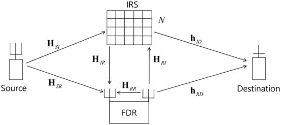
Figure 1.
Full-duplex relay channel with IRS support, where the DaF protocol is adopted at the relay.
At the time t, the SN transmits a unit-power message signal pre-coded by a unit norm vector toward the IRS and the FDR at the same time, where the FDR adopts the decode-and-forward protocol. The FDR decodes the signal and transmits the message at time if it succeeds in decoding with the decoding delay (We assume that the network is synchronized in frame level so that takes an integer value). The FDR applies an unit-norm vector to the receive antenna set and an unit-norm vector to the transmit antenna set. The IRS applies a diagonal matrix to the signal arriving at the N elements. The i-th diagonal element of is the phase shift value at the i-th element of IRS, where , for all . The received signals at the FDR and at the DN at time t are written, respectively, as follows (In this study, it is assumed that the channel state information is available at the FDR through some channel acquisition processes. As we assume a rich scattering propagation environment, all the elements of the channel vectors and matrices are assumed to be distributed. The only exception is the rank one FDR feedback matrix , where we assume that the channel between the transmit antenna set and the receive antenna set of the FDR is dominated by the line of sight link and all the scatter elements are far away from the antenna sets as discussed in [45]).
where and are the SN and the FDR transmit power levels, respectively; is the additive noise vector at the FDR with distributed elements and is the additive noise at the DN with distribution. The SI from the FD feedback loop is captured as two additive terms. One is for the direct path through and the other one is for the indirect path through . Here, the path-loss parameters , , and are introduced to emulate a typical case where the SI from the FD operation is dominating over the signal power levels from the SN at the FDR receiver (Note that the channel model in this paper follows those of conventional relay channels as appear in [27,28,29,30,31,32] while the only exception, path-loss parameters (, and ), are introduced for convenience in emulating the overwhelming self-interference (SI) power at the full-duplex relay (FDR) since this situation is hard to handle with the conventional relay channel models. The path-loss parameters provide a simple way to emulate this situation, as can be seen in Section 4 and in the reference [45] as well). We assume that an analog interference canceller (AIC) is applied at the FDR so that a large portion of the SI through the direct path is suppressed by the AIC and reflects the SI level remaining after the AIC.
The signal-to-interference plus noise ratios (SINR) at the FDR and the DN are then given, respectively as
Here, the ‘1’s in the denominators of the above two SINR expressions reflect the additive Gaussian noise power. And the throughput of the DaF relay channel is determined by the minimum of the above two links SINRs as . Therefore, the throughput maximization problem is formulated as follows:
The SI from the FD function, the minimum operator due to the DaF protocol and the unit norm phase restriction for the IRS reflection elements jointly contribute to making the problem highly non-convex and hard to handle. Further, the large number of optimization parameter vectors makes the problem even worse. A typical trick to handle such problems is an alternation-based approach, as is pursued in the work of the following sections.
3. Beamformer Design
This section provides three algorithms to be applied in the final alternation-based one. Each algorithm optimizes a set of vectors while the other sets of vectors are fixed and they try to maximize the metric in (4) so that the final alternation finds a certain local maximum in a few steps.
3.1. The Source Beamformer Optimization
Suppose the IRS phase shifter , the FDR beamformer set and are defined and that we need to find the source beamformer that maximizes the metric in (4). From the SINR expressions in (2), maximizes by aligning to the while maximizing lies in the null space of the vector . Let be the normalized vector of and . Here, the definition is the projection of onto the orthogonal space of , so that we may form with . It is evident that above formation of results in to be monotonically related with the variable while it makes to be a concave function of over the support region of . From such relations, we suggest Algorithm 1 to find when , and are fixed. Here, three different cases are taken into consideration depending on the beginning condition of and at and on the fact if these two gamma values meet or not on the support of .
| Algorithm 1 The source beamformer optimization algorithm |
|
3.2. The FDR Beamformer Optimization
Now, suppose the IRS phase shifter and the source beamformer are defined and we need to find the FDR beamformer set and that maximizes the metric in (4). Authors in [45] address the FDR beamformer design so that we can simply reuse the main results of [45] while we need necessary modifications in detail since we have additional channels through the IRS compared to the case considered in [45]. Recall that is a concave function of and is a monotonic function of , respectively, in Section 3.1. These properties are switched between and against the newly introduced parameter in this subsection so that the resulting beamforming algorithm resembles the one presented in Section 3.1 with little differences in detail. First, we may put for further simplifying the SINR expressions and then the first hop SINR can be written as with a definition . Also, we introduce a new definition and apply the following QR decomposition of two column matrix to get , where is an matrix with two ortho-normal columns and is a upper triangular matrix. In the two SINR terms in Equation (2), only the component of belonging to the column space of is relevant so that we may build the unit-norm FDR transmit beamformer as with , where a complex phaser is introduced to align the phases of the two complex numbers and .
Define , which gives us and . Consider the following singular value decomposition (SVD), with the unitary basis matrix , where the vector is the normalized and the matrix has column vectors from the basis vectors of the complement space of . We then are left with the singular matrix as . The optimal decision of and pair is presented in Proposition 1 of [45] as summarized as follows. Given , the SINR of the first hop is maximized by with the maximum SINR given as . Here, and with and . This results in the two-hop SINRs of (2) in functions of as
where . From these two SINR expressions, we can take an -based optimization approach for the given beamforming problem. As the overall SINR of the two-hop FDR channel is determined by the minimum of the two-hop SINRs, the optimal approach is equalizing these two-hop SINRs as appears in the following steps. It is obvious that is a monotonically decreasing function of and is a concave function of with the peak located at . As the local maximum of is given in a closed form, unlike the case of Section 3.1, we suggest an FDR optimization as appeared in Algorithm 2.
| Algorithm 2 The FDR beamformer optimization algorithm |
|
3.3. IRS Phase Shifter Optimization
In this subsection, the optimization of the diagonal matrix at the IRS is presented while the source precoder and the FDR beamformers and are defined. With the definition , and , we, first, consider the maximization of the numerator of problem (2) as
The authors in [22] show that phase alignment among the N different channel paths passing through the IRS achieves the optimal beamforming for , where the phases of N paths are all aligned to the phase of . In other words, or is the necessary condition of for . Since appears in the numerators and the denominators of the and ; and the minimum operator exists in (4), this rule requires more consideration and modification before it is applied to this problem. Note that the phase alignment of [22] corresponds to the equal gain combining (EGC) of diversity combining principle.
The approach we take in this work is to null out the terms that appear in the denominators while maximizing the minimum of the terms in the numerators of (4) at the same time. For these, we need some more definitions such as , and . We, then, can rewrite (2) and () as
Here, we try to make the magnitudes of the two terms and in the denominator to be near zero while the resulting and are almost equalized. To achieve the design objectives described above, a reasonable approach is a round-robin method, where each of four terms with is allowed to take up the IRS, in turn, to pick up a few IRS antenna elements with the strongest gain paths among the previously unselected antenna elements. Then, the phases of the selected paths are adjusted according to the design objective associated with the term. This process continues until all the IRS antenna elements are separated into members of 4 different groups related to the four terms. In this way, each term has an equal opportunity to share the IRS and to achieve the design objective of its own. At each round of IRS antenna selection, the number of selected elements is determined to equalize the numerator terms of and while a single antenna element is selected to null out each denominator term. Phase alignment of [22] is applied for the maximal gains of the two numerator terms and reversions of the phases after alignment depending on the interim sums of channel gains are applied to null out the two terms in the denominator.
After all the IRS antenna elements are grouped into four territories, the four sums of aligned channel gain approximately meet the design objectives. The IRS antenna elements outside of a group may cause a concern that their phases are not controlled to meet the design objective of the group. However, we assume that these elements make a negligible impact on the design objective as they are averaged out by the random nature of the phases. The above decision scheme is summarized in the Algorithm 3. To save computation, we may apply the Algorithm 3 until some number of elements less than N are selected and leave the remaining unselected ones with random phases leveraging the fact that the added channel gain sum from these elements is averaged out by the randomness. A similar idea is applied to the IRS-assisted multiuser channel in [25], where all the links to multiple users need to be treated with fairness.
| Algorithm 3 Φ decision algorithms |
|
3.4. Alternating Optimization and Computational Complexity
Overall optimization is conducted in an alternating manner between the Algorithm 1, the Algorithm 2 and the Algorithm 3, where the alternation starts with Algorithm 1 with a whose diagonal elements have random phases and random unit norm FDR beamformer vectors and . Algorithm 1 produces a unit magnitude AP precoder while Algorithm 2 outputs and ; and Algorithm 3 produces the IRS beamformer matrix , where each algorithm relies on the result of the other algorithms.
In the simulations, we see that the best combination of beamformers and the phase matrix is found within a few alternations. Note also that the parameter value search processes in Algorithms 1 and 2 can be done in a few steps, as well as they are simple variations of one-dimensional search problems involving concave functions. In the case of IRS phase shifter optimization, it is to determine the membership of the IRS elements based on the comparison of channel gain products that take up the biggest part of the computational load. Note also that most of the computations in the proposed algorithm rely on vector norm calculation operation and the QR decomposition and SVD. The last two are done only once per channel realization and their complexity is known to be . It turns out that affordable computational requirement is a considerable advantage of the proposed algorithm compared to other approaches with high complexity, such as semi-definite relaxation. Thus, we, in this paper, provide a computationally feasible solution with competitive performance, as can be seen in Section 4 to the joint optimization of the beamformer set and IRS phase adjustment matrix in the FDR channel with IRS support. Due to the large set of parameters and high non-convexity, the optimal solution is hardly acquired, and thus, this work, to the best of the author’s knowledge, lays the stepping stone to the problem.
4. Numerical Results
In this section, SINR results are compared in various simulation parameter settings. Three scenarios are compared, where only one of the IRS and the FDR or both of the two are actively helping the source to destination transmission. The last one corresponds to the scheme this paper proposes, while the other two cases act as the benchmark schemes. The IRS-only scheme applies the optimal phase alignment of [22] instead of the method in Algorithm 3 while the FDR-only case applies the algorithm in [45] without the feedback loop consisting of and corresponding to the reflection through the IRS. Three schemes are denoted as the proposed algorithm, the IRS-only and the FDR only, respectively. In all the simulation, more than one thousand channels are randomly realized according to their probability distributions and all the results are averaged out over these realized channel sets.
In Figure 2, the SINRs of compared three schemes are plotted as the ratio of the IRS-destination path gain () and the FDR-destination path gain () varies with the other parameters appeared in the caption. Here, is fixed and varies to reflect the situation the link strength between the IRS and the destination is varying. Note that the FDR-only scheme is not affected by this parameter variation; thus, its curve is flat. Strengthening the IRS-destination channel gain is directly reflected as the linear increase in the IRS-only curve while the proposed algorithm exhibits considerable gain at the low regime while the gain dwindles, unlike in the IRS-only case. This shows the limitation of the sub-optimal phase alignment algorithm in Algorithm 3 in harvesting the gain from using the IRS. The IRS only case optimally utilizes the strong link by aligning all the phases of the paths through the IRS elements, while the algorithm in Algorithm 3 shares the paths in optimizing four terms. A similar observation can be found in Figure 3, where the number of IRS reflecting elements N varies while the other parameters fixed. Again, the FDR only case is unaffected over this parameter variation since it does not utilizes the IRS reflecting elements. The other two curves show that they pick up the advantage of the increased number of elements into the benefit. However, the advantage of using the proposed algorithm diminishes compared to the IRS-only case in the high N regime. Conclusively, the proposed algorithm of jointly utilizing the IRS and FDR is helpful when the gain from using the IRS is marginal. The sub-optimality of the phase alignment algorithm in Algorithm 3 and the handling of feedback self-interference of FDR limits the usage of the proposed scheme only to the cases when the gain from IRS is marginal.
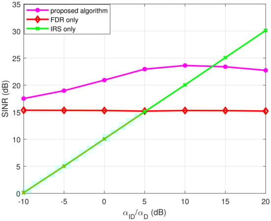
Figure 2.
SINR performance comparison over the ratio of the path gains () when and . Here, , and 10,000.
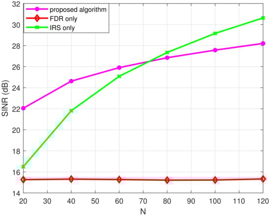
Figure 3.
SINR performance comparison over the number of IRS reflecting elements (N) when . Here, , and 10,000.
In Figure 4 and Figure 5, the IRS only case is unaffected and the corresponding curves are flat. The numbers of antennas at the source and the FDR vary in Figure 4 while the FDR transmit power varies in Figure 4. The other parameter sets are fixed in these two figures. The proposed algorithm shows improved SINR performances over those of the FDR-only case in the two simulations. The improvement is persistent over the whole range of the varying parameter sets and this result implies that FDR only case can be benefited by employing the proposed joint optimization of FDR and IRS. Note also that the slopes of the FDR only and the proposed scheme become slow as the number of antennas and the FDR transmit power grows, which comes from the fact that the feedback self-interference of the FDR becomes a hard challenge, and thus, it limits further improvement. These experiments lead us to a conclusion that the proposed algorithm improves the performance of the FDR-only case for a broad class of scenarios and parameter variations while it improves on the IRS-only case when the latter suffers in performance.
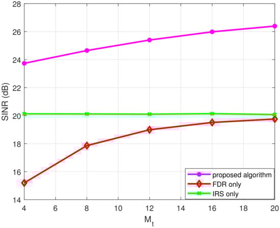
Figure 4.
SINR performance comparison over the number of antennas at the FD relay () when and with . Here, , and 10,000.
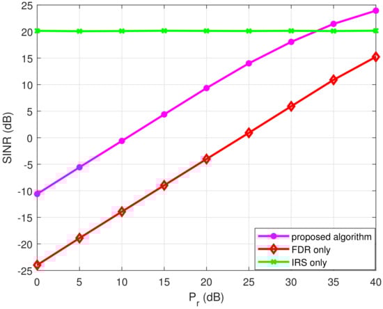
Figure 5.
SINR performance comparison as functions of the FD relay power () when and . Here, , and .
5. Conclusions
The full duplex nature of IRS and FDR suggests they can be a good match in delivering signals in weak links such as shadowed or cell edge users in cellular systems. We propose an optimization method for the joint DaF-based FDR and IRS system, which helps a source to destination transmission. The optimization of the beamformers at the source along with the FDR antenna sets and the phase adjustment of the IRS reflecting elements is considered. However, the increased number of links and their inter-relations in such a joint network makes the optimization very challenging since some links help the source to destination transmission while the others hinder it. To accommodate these conflicting requirements from different links, the IRS reflecting elements are judiciously grouped into a corresponding number of sets and the requirements are met separately by adjusting the phase values of the corresponding group. For the beamformer optimization, we parameterize the beamforming vectors, which results in two concave optimization problems for the source and the FDR relay set. These optimizations are implemented in an alternating manner. Simulation results are provided to illustrate the impacts of the proposed optimization algorithm in various implementation scenarios and parameter sets. These results reveal that the proposed joint algorithm enhances the FDR-only case regardless of the scenarios and parameter range. When it comes to the IRS-only case, the sub-optimality of the proposed algorithm makes it to be advocated only when the IRS-only case under-performs. Further improvement of the IRS phase adjustment algorithm may widen the regime where the joint optimization becomes more powerful.
Author Contributions
D.H. proposed the beamforming principles and associated algorithms for the FDR NOMA wireless networks; J.Y. and S.-S.N. supplemented in improving the algorithms; derived and analyzed all simulation results. Moreover, H.-K.S. provided the experimental materials for better computational simulations and revised critical errors of the manuscript. All authors have read and agreed to the published version of the manuscript.
Funding
This research was supported in part by the MSIT (Ministry of Science and ICT), Korea, under the ITRC (Information Technology Research Center) support program (IITP-2022-2018-0-01423) supervised by the IITP(Institute for Information & Communications Technology Planning & Evaluation), by the National Research Foundation of Korea (NRF) grant funded by the Korea government (MSIT) (NRF-2021R1F1A1047271).
Institutional Review Board Statement
Not applicable.
Informed Consent Statement
Not applicable.
Data Availability Statement
Not applicable.
Conflicts of Interest
The authors declare no conflict of interest.
References
- Ding, Z.; Krikidis, I.; Rong, B.; Thompson, J.S.; Wang, C.; Yang, S. On combating the half-duplex constraint in modern cooperative networks: Protocols and Techniques. IEEE Wirel. Commun. 2012, 19, 20–27. [Google Scholar] [CrossRef]
- Sabharwal, A.; Schniter, P.; Guo, D.; Bliss, D.W.; Rangaraian, S.; Wichman, R. In-Band Full-Duplex Wireless: Challenges and Opportunities. IEEE J. Selec. Areas Commun. 2014, 32, 1637–1653. [Google Scholar] [CrossRef]
- Wang, L.; Tian, F.; Svensson, T.; Feng, D.; Song, M.; Li, S. Exploiting full duplex for device-to-device communications in heterogeneous networks. IEEE Commun. Mag. 2015, 53, 146–152. [Google Scholar] [CrossRef]
- Liu, G.; Yu, F.R.; Ji, H.; Leung, V.C.M.; Li, X. In-band full-duplex relaying: A survey, research and challenges. IEEE Commun. Surv. Tut. 2015, 17, 500–524. [Google Scholar] [CrossRef]
- Riihonen, T.; Werner, S.; Wichman, R. Mitigation of loopback Self-Interference in Full-Duplex MIMO Relays. IEEE Trans. Signal Process. 2011, 59, 5983–5993. [Google Scholar] [CrossRef]
- Hwang, D.; Yang, J.; Nam, S.S. SINR maximizing Beamforming Schemes for the Full Duplex Amplify-and-Forward Relay Channel. IEEE Access 2017, 5, 18987–18998. [Google Scholar] [CrossRef]
- Hwang, D.; Hwang, K.C.; Kim, D.I.; Lee, T.J. Self-Energy Recycling for RF Powered Multi-Antenna Relay Channels. IEEE Trans. Wirel. Commun. 2017, 16, 812–824. [Google Scholar] [CrossRef]
- Day, B.P.; Margetts, A.R.; Bliss, D.W.; Schniter, P. Full-Duplex MIMO Relaying: Achievable Rates Under Limited Dynamic Range. IEEE J. Sel. Areas Commun. 2012, 30, 1541–1553. [Google Scholar] [CrossRef]
- Charlise, B.K.; Ma, W.K.; Zhang, Y.D.; Suraweera, H.A.; Amin, M.G. Optimum Performance Boundaries of OSTBC Based AF-MIMO Relay Systems With Energy Harvesting Receiver. IEEE Trans. Signal Process. 2013, 61, 4199–4213. [Google Scholar] [CrossRef]
- Cirik, A.C.; Rong, Y.; Hua, Y. Achievable Rates of Full-Duplex MIMO Radios in Fast Fading Channels With Imperfect Channel Estimation. IEEE Trans. Signal Process. 2014, 63, 3874–3886. [Google Scholar] [CrossRef] [Green Version]
- Cirik, A.C.; Hua, Y.; Latva-aho, M. Weighted Sum-Rate Maximization for Full-Duplex MIMO Interference Channels. IEEE Trans. Commun. 2015, 63, 801–815. [Google Scholar] [CrossRef]
- Suraweera, H.A.; Krikidis, I.; Zheng, G.; Yuen, C.; Smith, P.J. Low-Complexity End-to-End Performance Optimization in MIMO Full-Duplex Relay Systems. IEEE Trans. Wirel. Commun. 2014, 13, 913–927. [Google Scholar] [CrossRef]
- Zheng, G. Joint Beamforming Optimization and Power Control for Full-Duplex MIMO Two-Way Relay Channel. IEEE Trans. Commun. 2015, 63, 555–566. [Google Scholar] [CrossRef]
- Shim, Y.; Choi, W.; Park, H. Beamforming Design for Full-Duplex Two-Way Amplify-ad-Forward MIMO Relay. IEEE Trans. Wirel. Commun. 2016, 15, 6705–6715. [Google Scholar] [CrossRef]
- Heath, R.W.; Gonzalez-Prelcic, N.; Rangan, S.; Rho, W.; Sayeed, A.M. An Overview of Signal Processing Techniques for Millimeter Wave MIMO Systems. IEEE J. Sel. Top. Signal Process. 2016, 10, 436–453. [Google Scholar] [CrossRef]
- Han, S.; Xu, C.I.Z.; Rowell, C. Large-Scale Antenna Systems with Hybrid Analog and Digital Beamforming for Millimeter Wave 5G. IEEE Commun. Mag. 2015, 53, 186–194. [Google Scholar] [CrossRef]
- Molisch, A.F.; Ratnam, V.V.; Han, S.; Li, Z.; Nguyen, S.L.H.; Li, L.; Haneda, K. Hybrid Beamforming for Massive MIMO: A Survey. IEEE Commun. Mag. 2017, 55, 134–141. [Google Scholar] [CrossRef]
- Alkhateeb, A.; Ayach, O.E.; Leus, G.; Heath, R.W. Channel Estimation and Hybrid Prcoding for Millimeter Wave Cellular Systems. IEEE J. Sel. Top. Signal Process. 2014, 8, 831–846. [Google Scholar] [CrossRef]
- Ayach, O.E.; Rajagopal, S.; Abu-Surra, S.; Pi, Z.; Heath, R.W. Spatially Sparse Precoding in Millimeter Wave MIMO Systems. IEEE Trans. Wirel. Commun. 2014, 13, 1499–1513. [Google Scholar] [CrossRef]
- Wu, Q.; Zhang, R. Beamforming Optimization for Intelligent Reflecting Surface with Discrete Phase Shifts. In Proceedings of the ICASSP 2019—2019 IEEE International Conference on Acoustics, Speech and Signal Processing, Brighton, UK, 12–17 May 2019. [Google Scholar]
- Hu, S.; Rusek, F.; Edfors, O. Beyond Massive MISO: ThePotential of Data Transmission With Large Intelligent Surfaces. IEEE Trans. Signal Process. 2018, 66, 2746–2758. [Google Scholar] [CrossRef] [Green Version]
- Wu, Q.; Zhang, R. Intelligent Reflecting Surface Enahnced Wireless Network via Joint Active and Passive Beamforming. IEEE Trans. Wirel. Commun. 2019, 18, 5394–5409. [Google Scholar] [CrossRef]
- Wu, Q.; Zhang, R. Towards Smart and Reconfigurable Environment: Intelligent Reflectig Surface Aided Wireless Network. IEEE Commun. Mag. 2020, 58, 106–112. [Google Scholar] [CrossRef]
- Yuan, X.; Zhang, Y.A.; Shi, Y.; Liu, H. Reconfigurable-Intelligent-Surface Empowered Wireless Communications: Challenges and Opportunities. IEEE Wirel. Comm. 2021, 28, 136–143. [Google Scholar] [CrossRef]
- Cho, H.; Choi, J. Alternating Beamforming With Intelligent Reflecting Surface Element Allocation. IEEE Wirel. Comm. Lett. 2021, 10, 1232–1236. [Google Scholar] [CrossRef]
- Pan, G.; Ye, J.; Alouini, M.S. Full-duplex enabled intellignent reflecting surface systems: Opportunities and challenges. IEEE Wirel. Comm. 2021, 122–129. [Google Scholar] [CrossRef]
- Abdullah, Z.; Chen, G.; Lambotharan, S.; Chambers, J.A. Optimization of Intelligent Reflecting Surface Assisted Full-Duplex Relay Networks. IEEE Wirel. Comm. Lett. 2021, 10, 363–367. [Google Scholar] [CrossRef]
- Abdullah, Z.; Chen, G.; Lambotharan, S.; Chambers, J.A. A Hybrid Relay and Intelligent Reflecting Surface Network and Its Ergodic Perforamance Analysis. IEEE Wirel. Comm. Lett. 2020, 9, 1653–1657. [Google Scholar] [CrossRef]
- Bjornson, E.; Ozdogan, O.; Larsson, E.G. Intelligent Reflecting Surface Versus Decode-and-Forward: How Large Surfaces Are Needed to Beat Relaying? IEEE Wirel. Comm. Lett. 2020, 9, 244–248. [Google Scholar] [CrossRef]
- Sharma, P.K.; Garg, P. Intelligent Reflecting Surfaces to Achieve the Full-Duplex Wireless Communication. IEEE Commun. Lett. 2021, 25, 622–626. [Google Scholar] [CrossRef]
- Shaikh, M.H.N.; Bohara, V.A.; Srivastava, A.; Ghatak, G. Intelligent Reflecting Surfaces Versus Full-Duplex Relaying: Perforamnce Comparison for Non-Ideal Transmitter Case. In Proceedings of the PIMRC 2021—2021 IEEE 32nd Annual International Symposium on Personal, Indoor and Mobile Communications, Helsinki, Finland, 13–16 September 2021. [Google Scholar]
- Shafique, T.; Tabassum, H.; Hossain, E. Optimization of Wireless Relaying With Flexible UAV-Bourn Reflecting Surfaces. IEEE Trans. Commun. 2021, 69, 309–325. [Google Scholar] [CrossRef]
- Zhou, Z.; Ge, N.; Wang, Z.; Hanzo, L. Joint Transmit Precoding and Reconfigurable Intelligent Surface Phase Adjustment: A Decomposition-Aided Channel Estimation Approach. IEEE Trans. Commun. 2021, 69, 1228–1243. [Google Scholar] [CrossRef]
- Zhao, M.; Wu, Q.; Zhao, M.J.; Zhang, R. Intelligent Reflecting Surface Enhanced Wireless Networks: Two-Timescale Beamforming Optimization. IEEE Trans. Wirel. Commun. 2021, 20, 2–17. [Google Scholar] [CrossRef]
- Wang, P.; Fang, J.; Yuan, X.; Chen, Z.; Li, H. Intelligent Reflecting Surface-Assisted Millimeter Wave Communications: Joint Active and Passive Precoding Design. IEEE Trans. Vehic. Techno. 2020, 69, 14960–14973. [Google Scholar] [CrossRef]
- Tao, Q.; Zhang, S.; Zhong, C.; Zhang, R. Intelligent Reflecting Surface Aided Multicasting With Random Passive Beamforming. IEEE Wirel. Commun. Lett. 2021, 10, 92–96. [Google Scholar] [CrossRef]
- Zhou, G.; Pan, C.; Ren, H.; Wang, K.; Nallanathan, A. Intelligent Reflecting Surface Aided Multigroup Multicast MISO Communication Systems. IEEE Trans. Signal Process. 2020, 68, 3236–3251. [Google Scholar] [CrossRef]
- Li, Y.; Kudathanthirige, D.; Amarasuriya, G. Intelligent Reflecting Surface Aided Multi-Way Communications. In Proceedings of the PIMRC 2021—2021 IEEE 32nd Annual International Symposium on Personal, Indoor and Mobile Communications, Helsinki, Finland, 13–16 September 2021. [Google Scholar]
- Cheng, Y.; Liu, K.H.; Teh, K.C. Outage Perforamance of Downlink IRS-Assisted NOMA Systems. In Proceedings of the Globecom 2020—2020 IEEE Global Communications Conference, Taipei, Taiwan, 7–11 December 2020. [Google Scholar]
- Cheng, Y.; Li, K.H.; Liu, Y.; Teh, K.C. Downlink and Uplink Intelligent Reflecting Surface Aided Networks: NOMA and OMA. IEEE Trans. Wirel. Commun. 2021, 20, 3988–4000. [Google Scholar] [CrossRef]
- Cheng, Y.; Li, K.H.; Liu, Y.; Teh, K.C.; Karagiannidis, G.K. Non-Orthogonal Multiple Access (NOMA) with Multiple Intelligent Reflecting Surfaces. IEEE Trans. Wirel. Commun. 2021, 20, 7184–7195. [Google Scholar] [CrossRef]
- Lyu, J.; Zhang, R. Spatial Throughput Characterization for Intelligent Reflecting Surface Aided Multiuser System. IEEE Wirel. Commun. Lett. 2021, 9, 834–838. [Google Scholar] [CrossRef]
- Fascista, A.; Keskin, M.F.; Coluccia, A.; Wymeersch, H.; Seco-Granados, G. RIS-aided Joint Localization and Synchronization with a Single-Antenna Receiver: Beamforming Design and Low-Complexity Estimation. IEEE J. Sel. Top. Signal Process. To appear. [CrossRef]
- Najafi, M.; Jamali, V.; Schober, R.; Poor, H.V. Physics-Based Modelin and Scalable Optimization of Large Intelligent Reflecting Surfaces. IEEE Trans. Commun. 2021, 69, 2673–2691. [Google Scholar] [CrossRef]
- Kwon, K.; Hwang, D.; Nam, S. Beamformer Design for Self-Energy Recycling in Full-Duplex Decode-and-Forward Relay Systems. IEEE Wirel. Commun. Lett. 2020, 9, 1417–1421. [Google Scholar] [CrossRef]
Publisher’s Note: MDPI stays neutral with regard to jurisdictional claims in published maps and institutional affiliations. |
© 2022 by the authors. Licensee MDPI, Basel, Switzerland. This article is an open access article distributed under the terms and conditions of the Creative Commons Attribution (CC BY) license (https://creativecommons.org/licenses/by/4.0/).