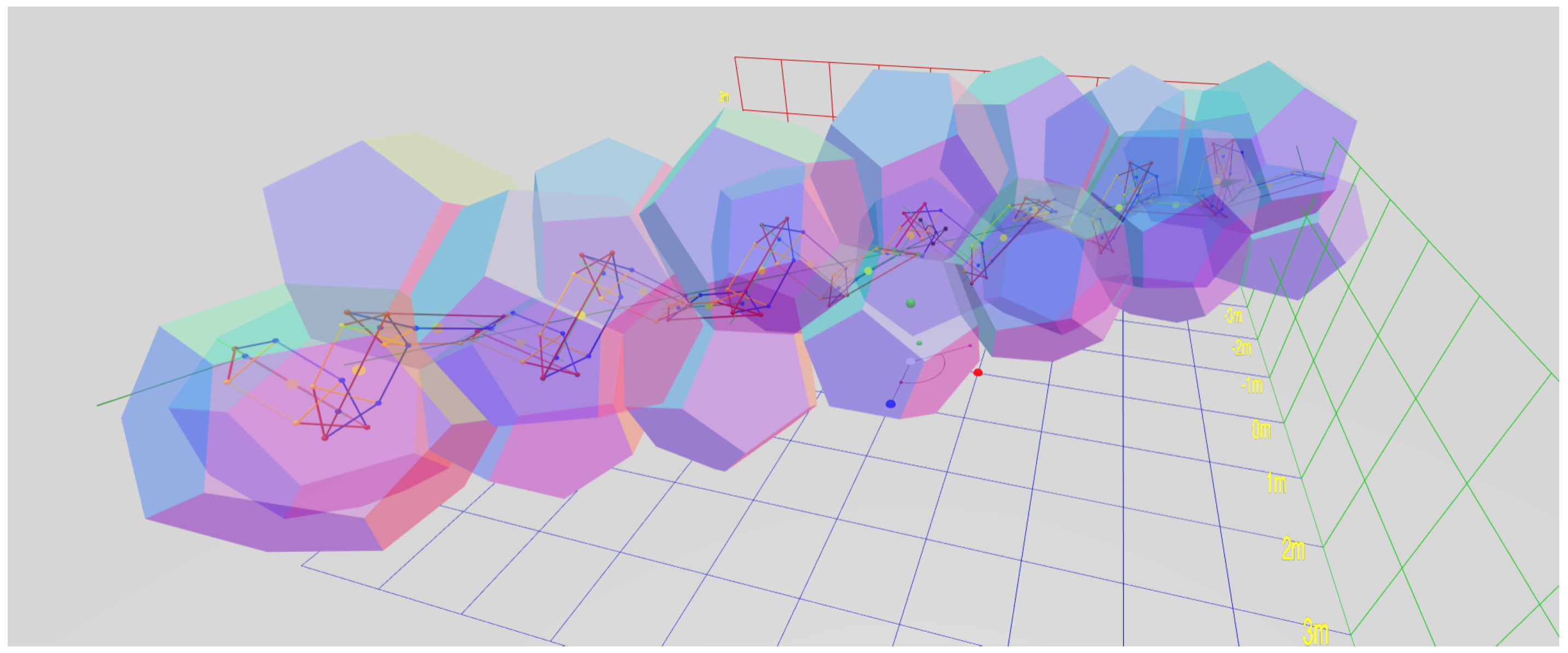
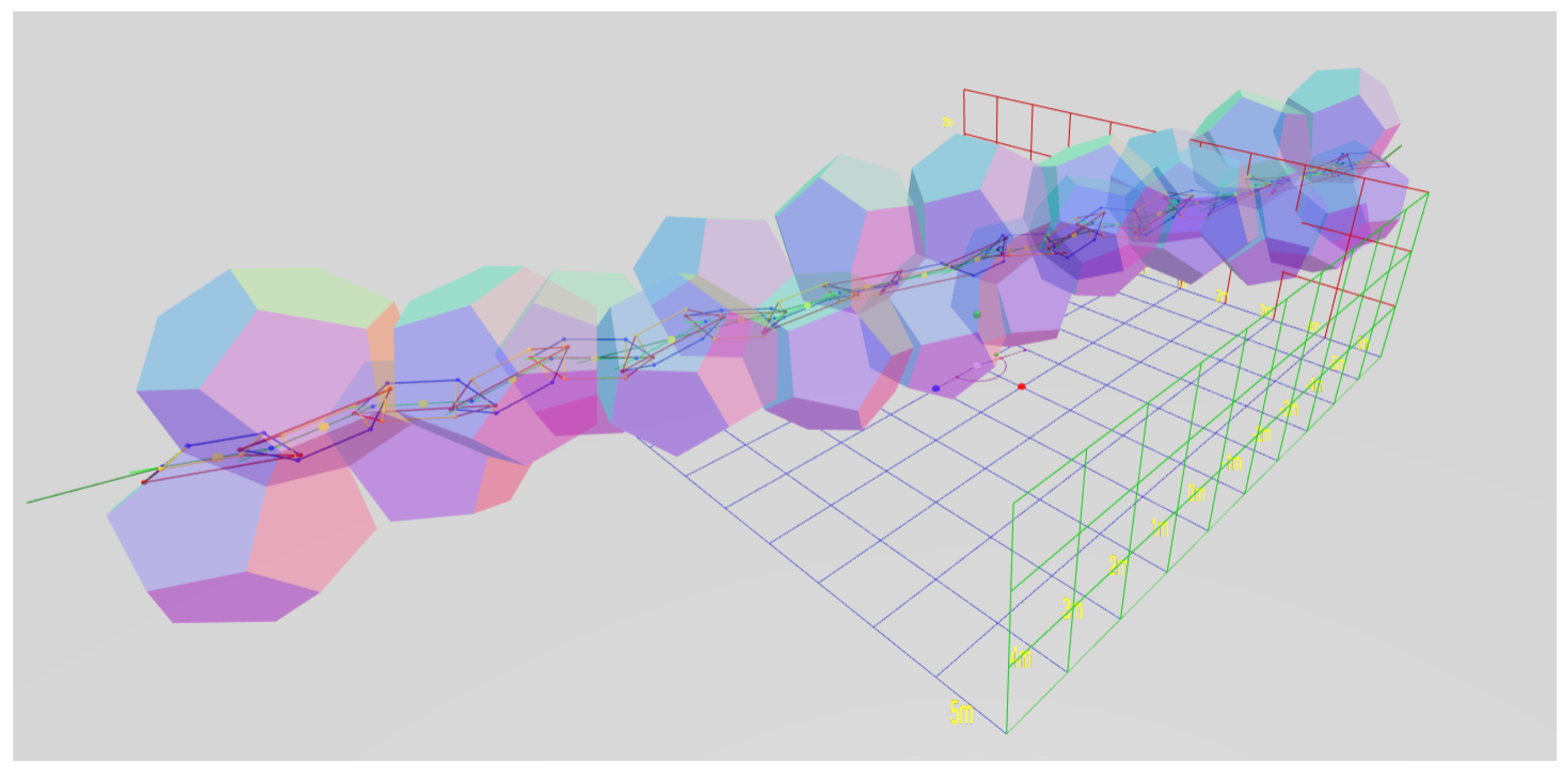
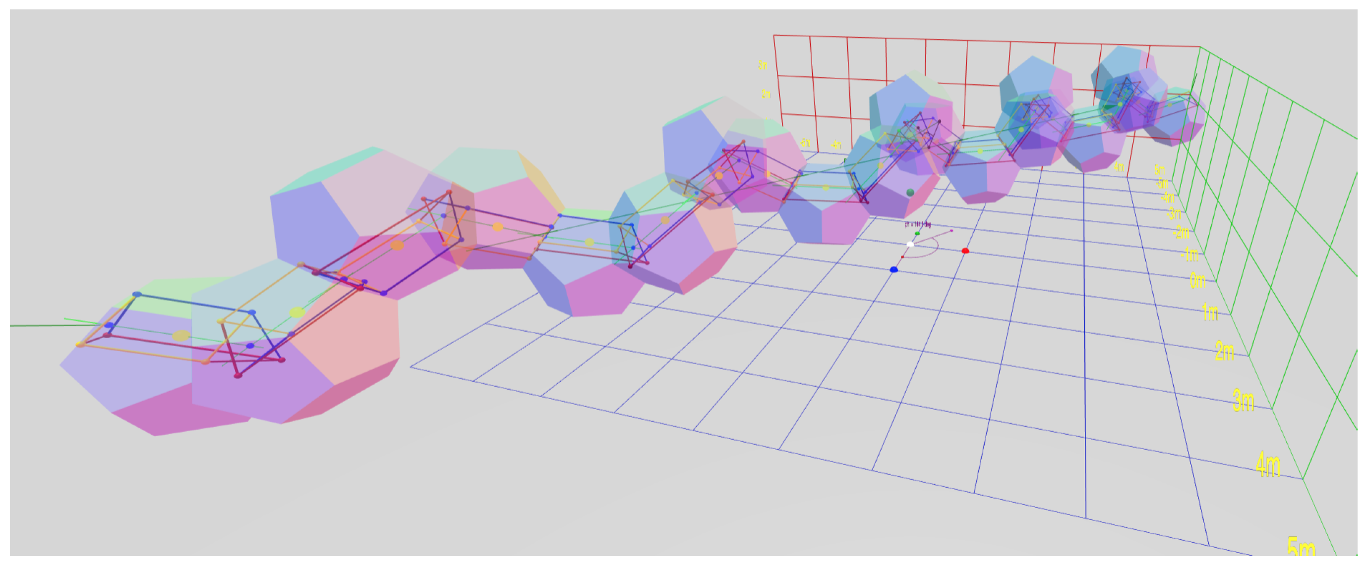
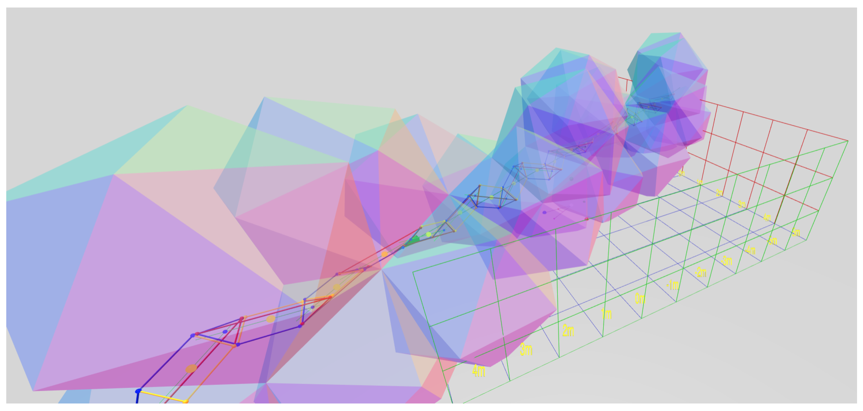
1. Introduction
During the Public Invention Mathathon of 2018 [
1], software was created to view chains of regular tetrahedra joined face-to-face. The participants noticed whenever the rules defining the face to which to add the next tetrahedron to were periodic, the resulting structure was always a discrete helix.
Although unknown at that time, this is a consequence of:
Observation 1 (Lord’s observation).
“In nature, helical structures arise when identical structural subunits combine sequentially, the orientational and translational relation between each unit and its predecessor remaining constant.” [
2]
Although fairly obvious in hindsight from screw theory, we have found no articulation of this statement in writing, so feel justified in naming it after the author of its earliest statement. The surprising fact that DNA is a double helix allows replication and RNA synthesis by the unzipping and rezipping of the helix. However, the fact that it is helical in nature is unsurprising, since it follows directly from Observation 1 and the fact that the strands of DNA are formed of repeated chemical units of approximately the same shape arranged sequentially.
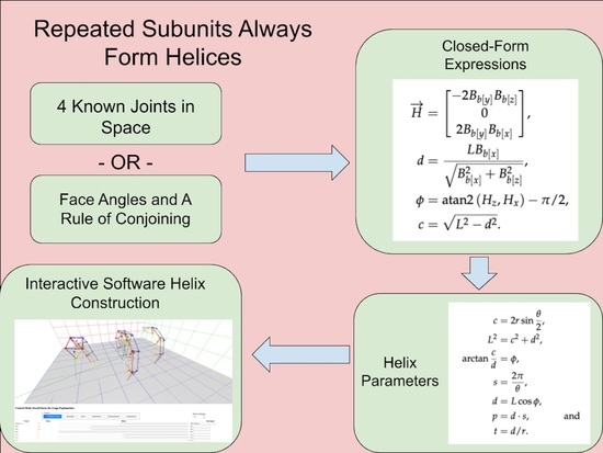
The purpose of this paper is to prove Observation 1 and provide mathematical tools and software for studying arbitrary segmented helices generated in this way.
Finding the properties of a segmented helix from three contiguous segments on the helix from screw theory [
3,
4,
5,
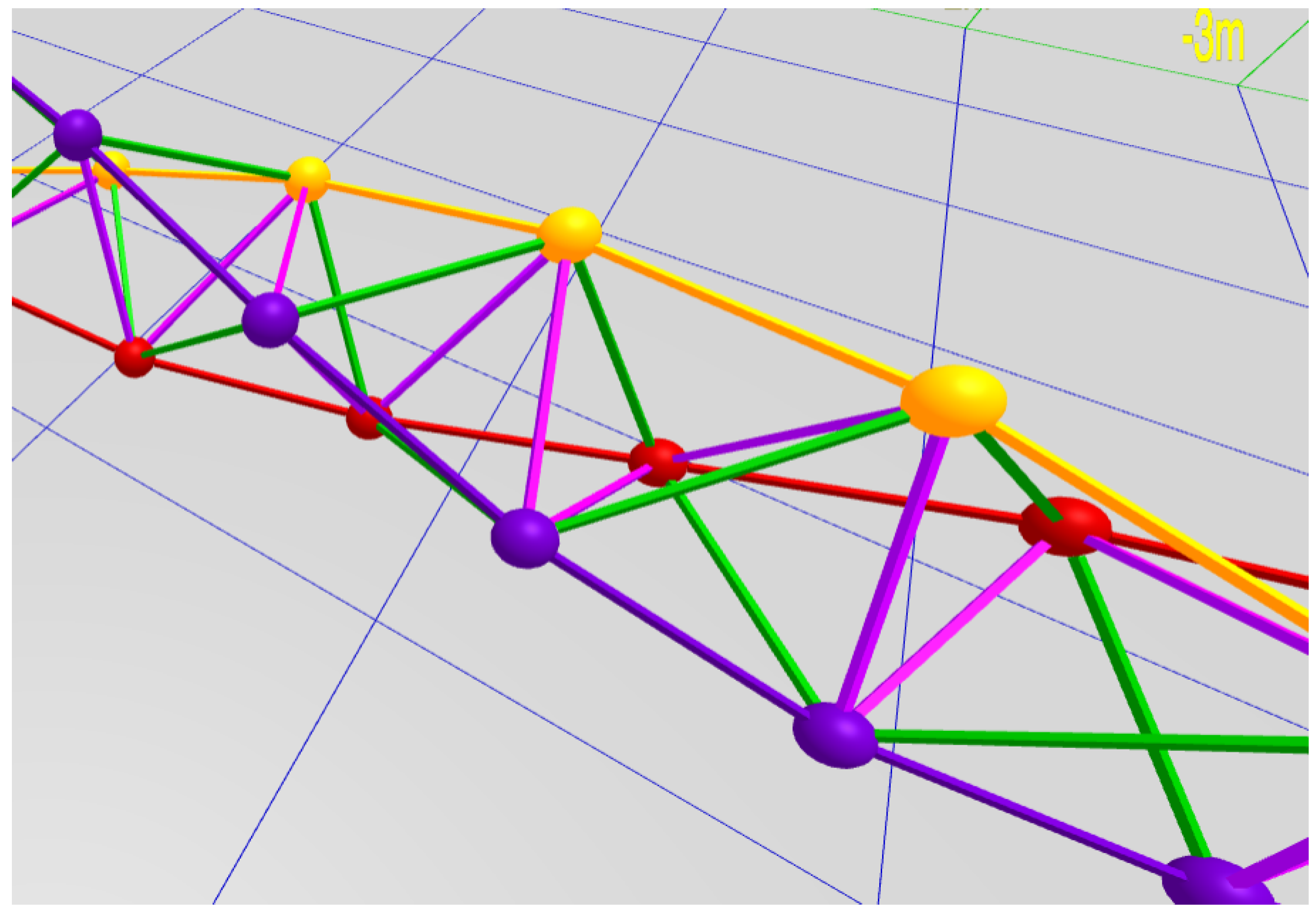
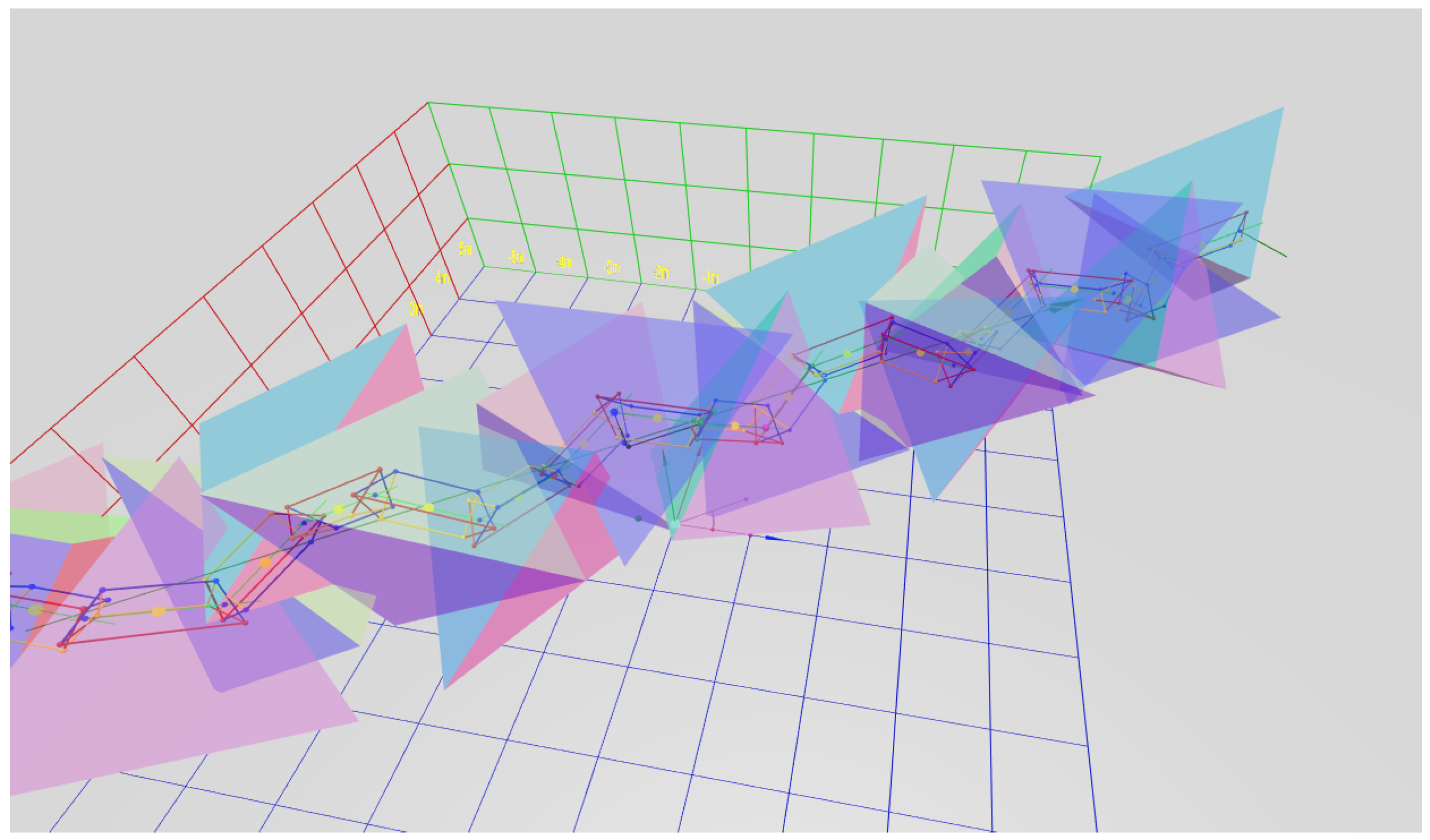
6], is explained and formulated. An interactive, 3D rendering website written in JavaScript [
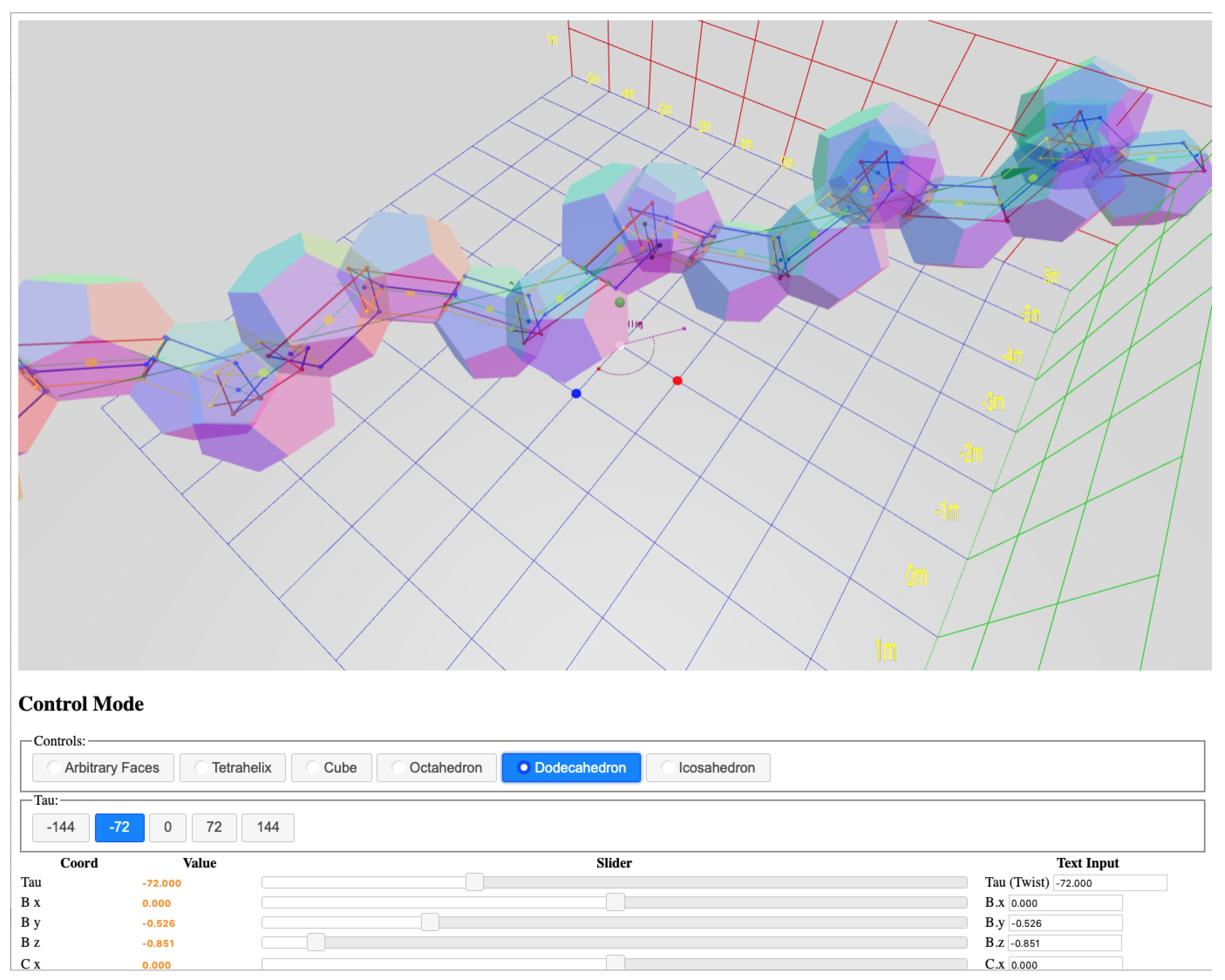
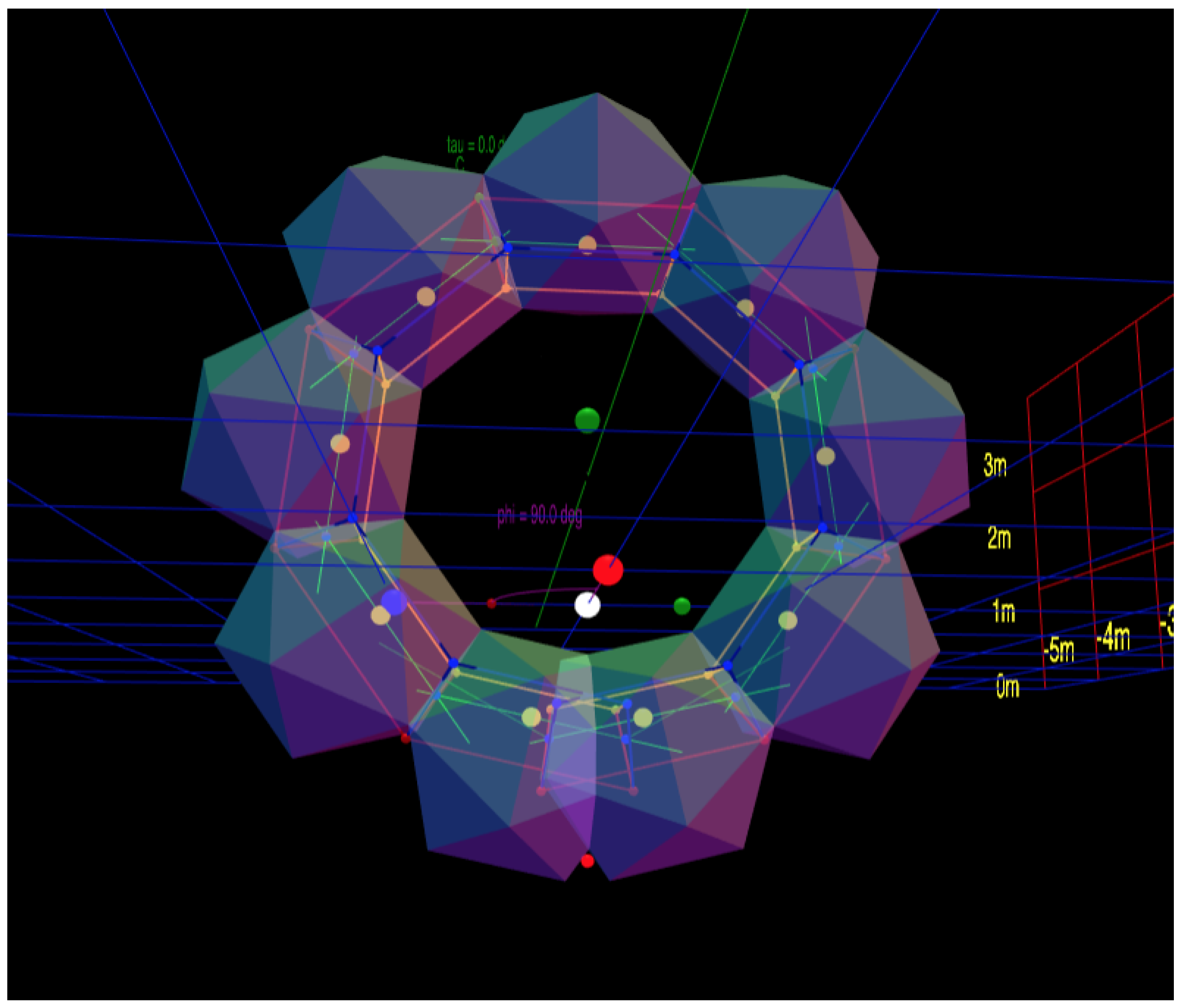
7] which allows both calculation and interactive play and study is provided [
8] (see
Figure 1). This allows a structure, or “molecule”, coincident to a segmented helix to be designed by adjustments to the repeated object, or for the shape of a repeated subunit to be inferred from the intrinsic properties of the segmented helix. Kahn’s method of helix fitting [
5,
9,
10] is modified to cover some degenerate situations.
We exploit Lord’s observation to discover symmetry which allows us to compute the helix when subunits are joined face-to-face with the same
twist. Kahn was investigating proteins, which do not have faces, but geometric solids and other macroscopic solid objects do. This concept can be generalized to a
joint face angle, even if the objects conjoined do not technically have flat faces. This symmetry allows us to compute the parameters of the segmented helix purely from properties intrinsic to a single object and the joining rule. We prove that varying the
twist of the joint faces through a complete rotation produces a smoothly varying spectrum of shapes that always includes a torus-like shape and a
zig-zag planar segmented helix of maximal extent. Finally, as an important demonstration, these tools are used to produce a catalog of all possible helices generated by vertex-matched face-to-face joints of the Platonic solids, of which only the tetrahelix [
11,
12,
13,
14,
15] has been completely described to date. This paper extends a very abbreviated conference paper which did not include the catalog of Platonic solids or all the calculations in
Section 2.3 and
Section 2.6, nor the proofs of Theorem 4 [
16].
1.1. A Warm-Up: Two Dimensions
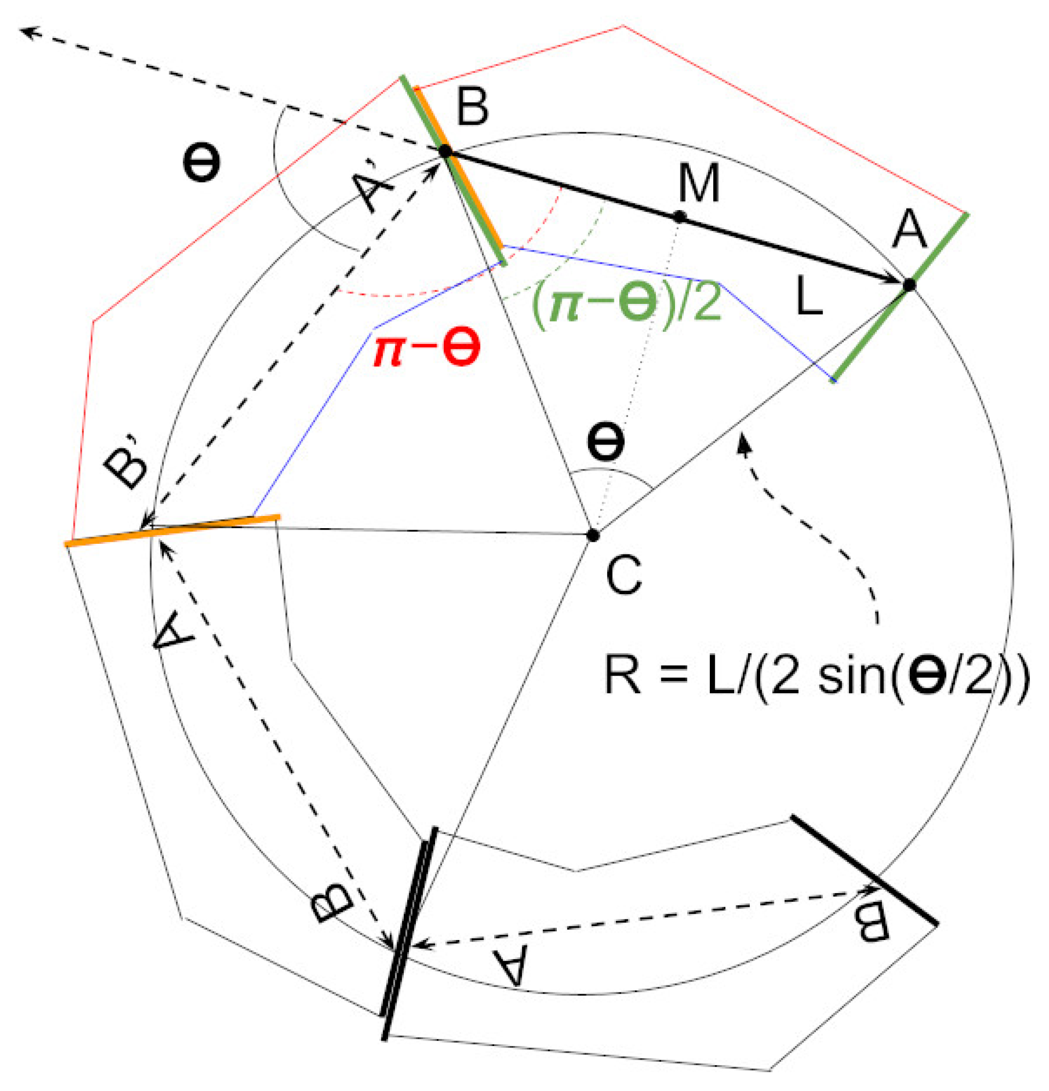
Considering the problem in two dimensions may be a valuable introduction. Suppose a polygon has two edges, called A and B, and the length L of the polygon is defined as the distance between the midpoints of these edges. Suppose these polygons are only joined by aligning A of one polygon to B of another polygon, with their midpoints coincident. Further, assume that inversions of the polygon are disallowed. Imagine there exists a countable number of polygons indexed from 0. Then what shapes can be made by chaining these polygons together?
Theorem 1. When polygonal subunits are conjoined with their axes at angle θ, they form a circle of radius:where if the circle is of infinite radius, that is, a straight line. Proof. Each joint between polygons and will place the axes of the polygons at the same angle, , since these polygons do not change shape. Define to be positive if we move anti-clockwise from to and negative if we move clockwise. If , the joints will be collinear.
If
, then form an isosceles triangle
in the direction of the second object, whose axis is
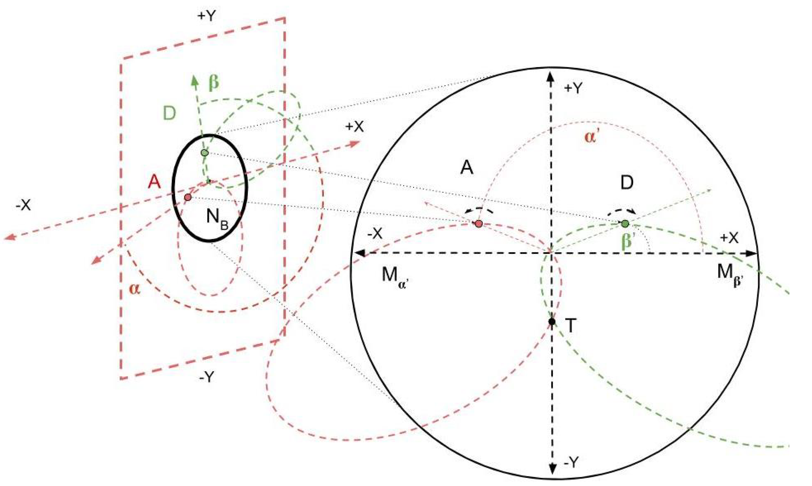
. Form this triangle so that one edge is a bisector of the angle between the axes
, as illustrated in
Figure 2. Make
.
Becuase
is a bisector of
,
. Therefore
. By considering the right triangle formed by midpoint
M of
and
C, the length of the sides
can be computed by the half-angle of theta:
Since the triangles formed by placing a new object are similar and share a side which is an angle bisector, they all share the point C. Therefore, the axis points A and B for each object lies on a circle of radius R with center C. □
1.2. The Segmented Helix
An analogous result holds in three dimensions.
Following the Wikipedia article [
17], a helix is set up parametrically:
Such a helix has a radius of r and slope (if ) of . The pitch of the helix—the change in t needed to make one complete revolution—is . Note that a helix may be degenerate in two ways. If , these equations become a line. If , these equations describe a circle in the -plane. If and , the figure is a point.
Such helices are continuous, but it is stacks of discrete objects under investigation. A goal is to derive the parameters for a continuous helix from such discrete objects by studying a helix evaluated at integral points. Call such an object a
segmented helix. A segmented helix may be thought of as function that, given an integer, gives back a point in 3-space,
where
d is the distance or
travel along the helix axis between adjacent joints. In this canonical representation the helix axis is the
z-axis.
is the rotation around the
z-axis between adjacent points.
r is the radius of the segmented helix. Note that if
, a third form of degeneracy (to the human eye) occurs: that of a segmented helix which is a zig-zag contained completely within a single plane.
If one thinks of the segmented helix as describing a polyline in 3-space, the properties of that polyline are of interest. Considering only the intrinsic shape of the segmented helix that are independent of position and orientation in space, there are three degrees of freedom: and .
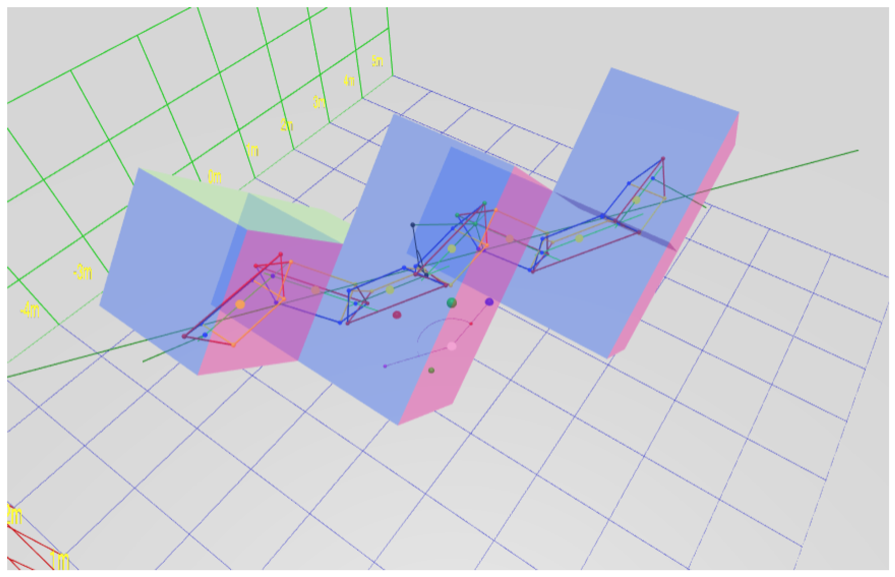
Figure 3 demonstrates naming convention concepts. It is a screenshot taken from the real-time interactive website [
8]. The software allows parallax by supporting interactive rotation, which makes the 3D structure easier to perceive; please visit the interactive page during this discussion of naming conventions.
In
Figure 3, and the website, we represent the object as a prism with a triangular cross-section, because this is the simplest physically realizable macroscopic object that supports a face-to-face connection. In this diagram, the points
, and
D are represented by the sphere of the same color as the label. The view is roughly in the direction of the axis of the segmented helix, which is drawn as a dark green arrow, pointing in the positive
z and positive
x direction, parallel to the
-plane. For ease of viewing, the entire segmented helix has been raised by two units on the
y axis. The segment
has coordinate
, is aligned with the
z-axis, and is centered in the
z direction.
The positive
and
z axes are shown by the red, green, and blue axis arrows, respectively. Following the computer graphics convention, the
y axis is oriented vertically. The points
, and
D correspond to
, and
, respectively, for a segmented helix aligned to the raised axis (not the
z-axis). A thin green polyline represents the segmented helix, and thus connects the joints
, and
D. The points are wrapping around the axis clockwise, with an angle of
as shown by the on-screen protractor as the rotation from one point to the next. As will be explained in
Section 2.15,
is the face-on-face joint rotation, in this case of 45°. The helix angle
is rendered by a protractor on the
plane; this is the angle between the axis of the helix and the
z axis, and therefore the angle of any one segment against the helix axis.
Any point on the segmented helix has a closest point on the axis of the helix. In particular, the points closest to the joints are called joint axis points. Then d is the distance along the axis between consecutive joint axis points.
A line is drawn from the blue point B to a black sphere on the helix axis, the joint axis point, denoted . Analogously, is the point on the axis closest to the green point C.
A segmented helix located in space is completely determined by the parameters , a vector describing the axis of the helix, and the position of any one joint.
Because the segmented helix is a discrete structure, one can reframe the concept of pitch as sidedness s: how many segments (sides) make a complete rotation?
The following concepts and conventional variable names for them will be related:
L is the distance between any two adjacent joints (between B and C, for example).
r is the distance between a joint and the helix axis (between B and for example).
is the rotation about the helix axis between two consecutive joints.
c is the length of a chord formed by the projection of the segment between two points projected along the axis of the segmented helix (a chemist may recognize this as the distance between residues on a helical wheel projection).
d is the distance along the axis of the helix between any two joint axis points (between
and
in
Figure 3, for example, rendered as a small black and blue sphere, respectively).
is the angle between any vector between two adjacent joints and the axis of the helix. In physical screws used in mechanical engineering, this is analogous to the
helix angle [
18].
p is the pitch of the helix, the distance traveled in one complete rotation.
s is the number of segments in a complete rotation (in general not rational).
Finally, we find it useful to define the tightness of a segmented helix as travel divided by radius, a number analogous to the extension of a coil spring or slinky. A torus-like segmented helix has zero tightness and a zig-zag has maximum tightness. The letter t represents tightness.
These quantities are related:
Measuring demands a decision on the sign of the direction of the axis, which is arbitrary and not based on the physical shape.
Section 2.3,
Section 2.6 and
Section 2.15 relate these properties to properties intrinsic to the joint or interface between two segments or objects in the segmented helix.
1.3. Sign Conventions for Spatially Located Segmented Helices
When thinking about the overall shape of a segmented helix, one is likely to be interested in the absolute magnitude of its intrinsic properties.
However, when doing computer graphics work or kinematic calculations, the sign conventions are critical. Because this paper wishes to emphasize the continuum of shapes produced by changing an object used to generate the segmented helix, and, in particular, is interested in the degenerate helix which produces toroidal figures, it is preferable to be able to discuss the axis of a segmented helix as existing even when the figure has no travel along the axis (that is, when ).
Therefore adopt the following conventions:
A right-handed coordinate system.
The helix axis is a normalized vector which never vanishes.
The travel along the axis (d) is negative when the helix is anti-clockwise (that is, when motion from joint n to joint appears anti-clockwise when , zero when toroidal), and positive when the helix is clockwise.
is never negative.
2. Results
2.1. The Intrinsic Properties of Periodic Chains of Solids
Although fairly obvious from Chasles’ Theorem, in order to prove Observation 1, additional clarification is helpful. If chains of identical repeated 3D units are conjoined identically, they are periodic chains, and they generate a segmented helix coincident on their joints. Identical objects conjoined via a rule produce periodic chains of objects that are uniformly intersected by segmented helices and may be degenerate in one of three ways that might not strike the human eye as a helix at first glance:
- (1)
The segments may form a straight line. (For example, see Figure 14).
- (2)
The segments may be planar about a center, forming a polygon or ring. (For example, see Figure 20).
- (3)
The segments may form a planar saw-tooth or zig-zag pattern of indefinite extent (For example, see
Figure 4).
There are two complementary ways of learning about such segmented helices. In one approach, we may have knowledge of the segmented helix and wish to learn about the subunits and the rule with which the subunits are combined. For example, we may have microscopic objects such as proteins or atoms, and we know from crystallography something about the positioning of these objects, without knowing ahead of time the angles at which these objects would combine in their natural environment. In this case, we use a variant of a linear algebra method [
5] for determining the radius, travel, and “twist” of the segmented helix (
twist will be defined precisely below).
In the other approach, one may know a priori exactly the relevant properties of the objects and the rule with which they combine and seek to compactly describe the segmented helix they create. For example, a mathematician may consider a chain of dodecahedra, or a woodworker may cut identical flat-faced chunks of maple wood, which are to be glued together face-to-face. In these cases, everything about the objects and the rules for conjoining is known before the first two objects are glued together. Call this the joint face normal method, because it can be simulated by joining two flat faces together with a specified twist, even if the objects in question do not actually have a physical face (such as molecules).
In both cases, it is useful to understand how a change in a face normal or a twist affects the parameters of the segmented helix, and, conversely, useful to be able to choose the construction of the subunits to achieve a particular segmented helix.
In engineering, sometimes the term
special helix [
19] is used for helical curves on non-cylindrical surfaces. This paper uses the term
helix only in the sense of
cylindrical helix.
2.2. Periodic Chains Produce Segmented Helices
A periodic chain is, in fact, a simple object which demonstrates tremendous symmetry. Before using this symmetry in the construction of the segmented helix corresponding to a periodic chain, it is valuable to prove that such a segmented helix indeed exists for every periodic chain. Because periodic chains are merely a clarification of the “identical structural subunits” of Observation 1, this theorem proves that observation.
Theorem 2 (Segmented Helix). Consider N identical objects which each have two points, A and B, called joints. Call the axis of this object. Consider the frame of reference for this object to have its axis on the z-axis with B in the positive direction, the midpoint of the object being at the origin.
Consider any rule that conjoins A of the object to B such that from the frame of reference of i, the object and anything rigidly attached to it is always in the same position in the frame of reference for i. Informally, “looks the same” to i, no matter what i is chosen, . Call a chain of N identical rigid objects conjoined via a rule that conjoins to in such a way that every vector rigidly attached to object is always in the same position relative to the frame of reference constructed from object i, a periodic chain.
Any periodic chain of three or more objects has a unique segmented helix whose segments correspond to the axes of these objects.
Proof. By induction.
Base Case ():
Take an object
A with axis
. By Chasles’ theorem [
20] there is a screw axis
, a set of rotations, and a transposition
d which moves the first object to the position where the second object
B with axis
is. Take one of the rotation angles of smallest value. Construct the points
,
and
as the closest points to
and
C on this screw axis. These points are collinear by construction.
Now add the object to object by the rule of periodic chains. Consider the points and from A’s frame of reference. Let . Construct the point on the screw axis as the point closest to D on that line.
Because in object B’s frame ofreference must look like in A’s frame of reference, the distance . From A’s frame of reference, are collinear, so the points must be collinear in B’s frame of reference.
In any frame of reference, if are collinear and are collinear, then are collinear.
Now, looking backward from towards A, the length must be the same as the length so as to not violate the rule. So . Similarly let . Then by construction. By the rule of conjoining, the vector is a rigid transformation of , so . By symmetry, . Compute as the rotation about that takes into . By the rule of attachment, also takes into and into .
Next, construct a segmented helix, of radius r, distance d, and angle . The segmented helix axis and joints can be positioned coincident with the screw axis so that . Then , , and .
Therefore, for the base case of three objects, there is a segmented helix whose segments coincide with the axes of the objects.
Inductive Case ():
Assume there is a segmented helix coinciding with the first k objects, and consider the frame of reference of the kth object. The axis and any other rigid property of the th object stands in relation to object k as k stood to .
By the assumption of induction, the kth object has an axis coincident to a segment of a segmented helix. Attach vectors and from the joints of object k to the corresponding axis joints of the segmented helix perpendicularly. Define these vectors in the frame of reference for k.
To the th object, the tips of and vectors ( and ) define a line segment which lies on the axis of the segmented helix H, with the tip of coincident with the tip of .
By the rule of conjoining and by induction, since this is true of the th object, it is true of the kth object. Therefore the tips of the th object’s attached vectors and form a vector which lies on the axis H, extending it in the same direction. The joint axis of the th object therefore coincides with the th segment of H.
Therefore, by induction, identical objects conjoined by the same rule always coincide with some segmented helix, whose parameters are discoverable. □
In engineering, the term helix angle refers to the angle between a line tangent to a continuous helix and the axis of the helix. In segmented helices, this is the same as the angle between the axis of each object in a periodic chain and the axis of the segmented helix coincident to it.
Consider objects which are, taken as individuals, highly asymmetric. For example, the B face does not have to be the same size as the A face. In fact, the object itself might be shaped like the letter “C”, and not completely enclose the axis. Taking the idea further, the object might be spiky, such as a stellated polyhedron or a sea urchin, and still be joined by joints relatively close to the center of the object. (This paper does not address the issue of self-collision of the objects, which would have to be considered if attempting to make a period chain of sea urchins).
It is perhaps not obvious that building a chain of such objects produces a segmented helix, and therefore that the helix angle is the same for each object, but this is a corollary of Theorem 2.
Corollary 1 (Segment Similarity). The helix angle of any object axis in a periodic chain is the same.
Proof. The axes of each object coincide with a segment of a segmented helix. A segmented helix is completely symmetric no matter in which direction of the axis you look down or at which point on the axis you begin. The angle between each pair of objects is exactly the same. □
Corollary 1 will be used in the development of PointAxis algorithm, in the computation of segmented helix properties, to justify balancing face normals to produce an intrinsic out-vector, and to apply the PointAxis algorithm without actually assigning objects Cartesian coordinates.
2.3. Computing Screws and Segmented Helices from Transformation Matrices
The rule for how objects in a periodic chain are joined may be conveniently captured as a transformation matrix. In general, a human engineer will have to compute this transformation matrix from some other information, such as the face-to-face conjoining rule. We discuss how to do this from joint-face normal vectors in
Section 2.15. However, a transformation matrix clearly captures the idea of repetition. Since by definition the objects in the chain are the same shape, moving one object into a new position and placing an identical copy of that object in that position are practically the same.
Using standard screw theory [
3,
6], a screw can be computed from such a transformation matrix. This consists of the axis of the screw
, a point on the screw axis
P, the rotation
around the axis, and the transposition, or travel, along the axis of one transformation.
Neither a transformation matrix nor its corresponding screw transformation completely defines all of the intrinsic properties of a segmented helix. In particular, a matrix maps any point p to a point . Since this applies to all points no matter how far from the screw axis (axis of rotation), and such transformations preserve distance to this axis (the radius), the radius of a segmented helix is not determined by a transformation matrix or a screw. Since the helix angle changes with a radius for a helix of a given pitch, is not determined.
However, given a screw and one point on the axis of the screw fixing it in space and the location of one joint, all of the properties of the segmented helix are completely determined.
The software behind the interactive website implements the calculation of the screw directly from a transformation matrix, and the additional routines which determine all intrinsic properties from a joint position (making certain arbitrary alignment choices without loss of generality).
Although not original to this paper, it is difficult to find clear documentation on how to calculate the screw from the transformation matrix. We therefore include an exposition here, in the hope that it will be a useful and valuable addition to the code in the source code repository to a programmer seeking to duplicate this functionality.
2.4. Computing the Screw Axis from a Transformation Matrix
The goal is to compute a normalized vector aligned with the screw axis of the transformation composed and effected by a transformation matrix .
In order to be robust, it is valuable to check that the transformation matrix is a rigid transformation [
21], as Chasles’ theorem applies only to rigid transformations. Transformation matrices in homogeneous coordinates, as typically used in kinematics and computer graphics, are convenient for this purpose, allowing the transformation represented by a matrix to be affected by simple multiplication.
The angle of rotation is computable from the trace of
,
:
Technically, arccos is multi-valued, but take
to be in its principle range,
. If
is 0 or a multiple of
, then we have the zig-zag degenerate case; the method of computing
from the rotation basis of
is numerically unstable. However, in this case we can compute the direction vector
as the difference vector between an arbitrary point
q (a 4 × 1 vector in homogeneous coordinates) and its transformation performed twice. Informally, this is a “zig, then a zag”:
(Note that in general is not normalized, . Additionally, recall that multiplication by a transformation matrix produces a point that is in a new position representing the transformation).
In other cases,
can be computed from the direction cosines of
[
22]:
The variables and are primed to distinguish them from the symbols for the chord c and the travel along the axis d). The magnitude of , which vanishes when is 0 or multiple of , hence the need to treat those cases differently.
2.5. Combining a Single Joint with the Matrix
The vector
gives the direction of the axis of the helix, but does not give a point that fixes it in space. Although the matrix
in general produces both a rotation and a translation in space, the distance between
q and
in general depends on how far
q is from the axis of rotation. If, however, we are given a single joint
B in addition to
, then we can completely determine the entire segmented helix.
C is computed from
:
Then
d is computable as a projection:
These are the only properties that can be computed from the matrix
alone, but given the length
L along the object axis (
not the helix axis) of an object the helix parameters are computable, based on relations already given in
Section 1.2.
The chord of the segmented helix (that is, length of an object of axis length
L projected along
) is:
Knowing the chord
c and the amount of rotation
allows us to compute the radius:
unless the chord is 0, in which case the radius is 0. The helix angle
is a a function of
c and
d:
Sidedness and pitch (s and p) follow directly.
From these one may produce the joint axis point which is the point on the helix axis closest to B.
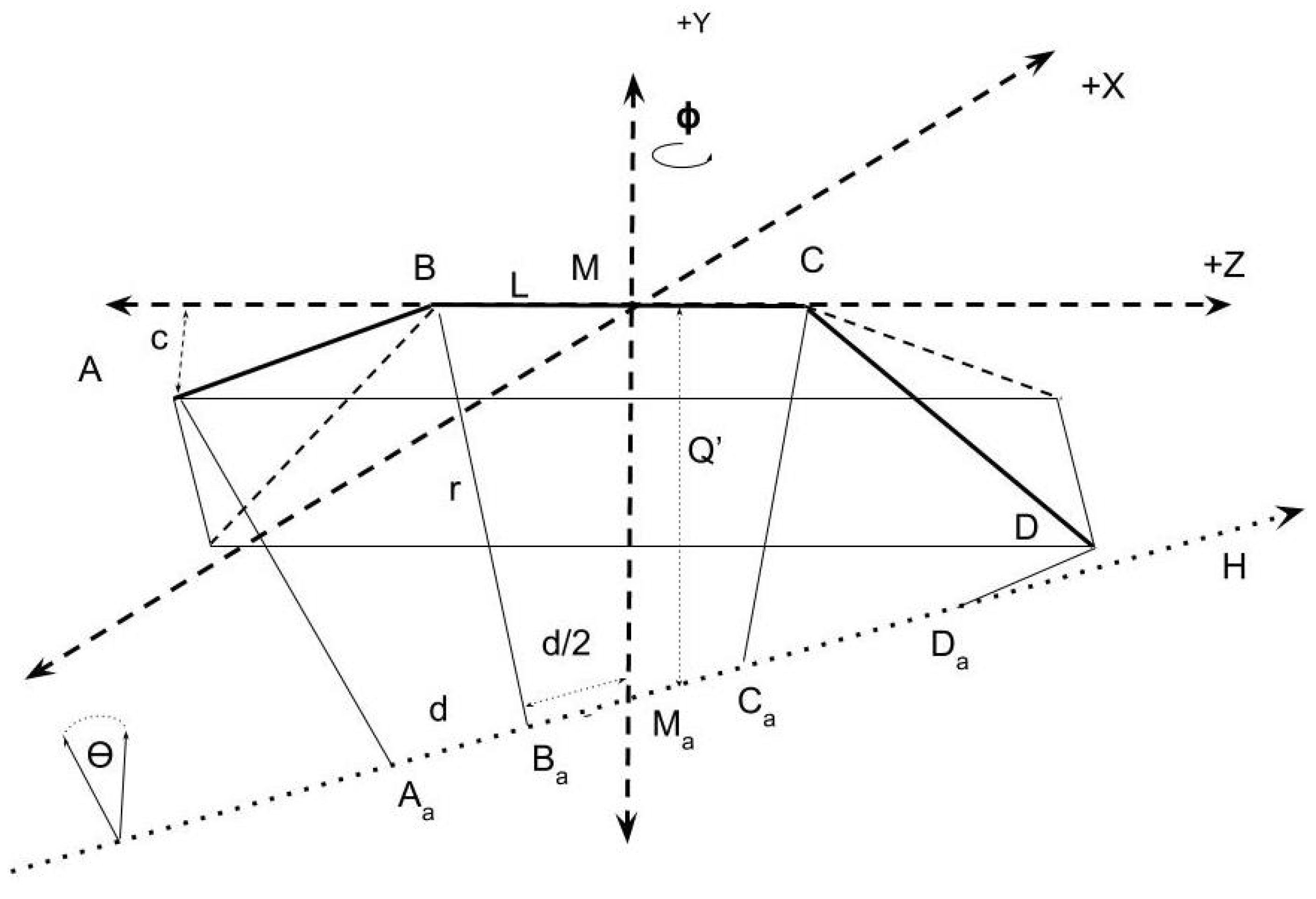
Figure 5 may be useful in picturing the following quantities. To do this, conceptually construct the midpoint,
of
and utilize the fact that the vector from
to its closest point on the axis
(call this vector
) is perpendicular to both
and
. Therefore, its direction is constructible via cross product, and its length
l is computable from the radius and chord.
is the midpoint of
and
, so just move back half the travel
d along the vector
H to get
.
Thus, given only the transformation , the length L, and one joint B, one may compute all of the intrinsic properties () of the segmented helix and position it in space via and .
As is common in kinematics [
23], there are many ways to represent the same physical or mathematical situation. Four consecutive joint positions also completely determine a segmented helix, as presented below. Because joints can be computed from transformation matrices and transformation matrices from joints, which method of calculation is preferable is largely a matter of choice and clarity. The code at the interactive website in fact codes both approaches and compares them as an automated test to ensure correctness.
A mechanical engineer, roboticist, or computer graphics expert is likely to find the computation from the transformation matrix more natural and convenient. A chemist or crystallographer is more likely to have learned the position of four points and wish to compute from that.
2.6. PointAxis: Computing Segmented Helices from Joints
Kahn [
5] has given a method for computing the axis of a helix in the context of chemistry. This method uses the observation that the angle bisectors of the segments on a segmented helix are perpendicular to and intersect the axis of the helix. Because chemical helices may not be perfect and because the measurement of positions may not be perfectly accurate, it is common for chemists to use regression and fitting methods to fit helix parameters to observed positions on the helix. Kahn’s method was a prelude to some error-tolerant methods applicable to the realm of organic chemistry [
9]. This paper is concerned only with pure geometry. Furthermore, Kahn was writing in 1989, and more convenient computing tools are now available. The algorithm presented, called
PointAxis, here can be considered a modification of Kahn’s algorithm, which relies on the ability, working in the realm of pure geometry, to position the segments on the axes to simplify the derivation and computation.
2.7. A Sketch of the 4-Point Method
Using tools from linear algebra and well-documented algorithms, a sketch of finding the segmented helix from four consecutive known points , and D is:
Construct a rigid transformation that places the points conveniently on the z-axis and balanced around the y-axis.
Compute the bisectors of the angle between object axes , called and the bisecting angle of . If the points are collinear, they are a special case.
Because these angle bisectors point at the axis of the segmented helix, their cross product is a vector in the direction of the axis. If and are parallel or anti-parallel the cross product is not defined and we have special cases.
Otherwise the vectors and are skew, and the algorithm for the closest points on two skew lines provides two axis points and on these vectors which are the closest points on those lines and are also points on the helix axis.
The distance between and B is the radius, and the distance between and is the travel d along the axis.
The angle between and is .
2.8. Rotating into Balance from Face Normal Vectors
In order to use the PointAxis algorithm, we need a way to compute points A and D in balance around the axis .
Figure 6 shows a downward view of a balanced configuration (though raised above the origin instead of at the origin).
A (the red sphere) is a reflection of
D (the purple sphere) across the
y-axis. Both
A and
D are hanging downward. If the structure were hung on a point at the origin, it would be physically balanced. As shown in the following, it is always possible to achieve this balance, even though a single object itself is not symmetric; in this figure, the normal of the
B face is not symmetric with
C face.
That this is always possible is important enough, if only for the convenience of calculation, that we consider it a Lemma:
Lemma 1 (Balance Lemma). For any segmented helix with selected consecutive joints and D, there is a rigid transformation that positions it such that:
The segment is centered on the z-axis: .
The joints A and D are in rotational balance about the y axis, as if they were weights hanging downward: and .
Proof Sketch of Lemma 1. A key insight is that Theorem 2 implies that no matter how lopsided and different the normal vectors and for the joint faces are and no matter what we choose, the relationship of conjoined objects is always the same. After placing along the z-axis, there is always an angle which will rotate the points A and D into balance (that is, ).
The key to finding
is to note that the projections of the
B and
C face normal vectors projected into the
plane can be rotated so that they are balanced around the negative
y unit vector. Such a projection into the cross-section of the helix is closely related to the
helical wheel [
24] plot in the study of alpha helices in proteins. Even if the lengths of the projections of the face normals in
are different, this mechanism works, because by Observation 1 and Theorem 2, the points
A and
D must be symmetric about the segment
.
By composing this balancing operation with the face-adjoining transformation matrix via
adjoinPrism (see
Section 2.16),
A and
D are placed in balance.
Note that in the zig-zag case, . □
The screw axis may now be computed from either the four points , and D or from the transformation matrix created to balance them.
2.9. On the Choice of the Screw Axis Direction
Given only a segmented helix without a position in space, the choice of direction for the axis is arbitrary. Changing the decision will make the screw axis point in the negative direction, change the sign of the travel d along the axis, and change to be .
As can be seen from interactive play with the website [
8], it is entirely possible for the travel along the axis of the helix to be 0. In fact, choosing
tends to produce toruses, which have no travel along the axis.
One could choose to represent this by making the unsigned length of the vector representing the axis be the length of the travel d. However, this would have the drawback that when d is zero it would be impossible to determine the axis of revolution of the torus. Although somewhat arbitrary, we have chosen instead to represent the axis as a normalized vector of unit length and to allow the travel to be negative. This has the benefit that changing through (something close to) zero smoothly changes d. However, it creates the problem that as approaches (something close to) from different directions the signs of the axes are different. That is, and describe exactly the same shape, but in our calculation, they will have different signs for the axes. The radius, pitch and absolute value of the travel, which are intrinsic to the shape, will be the same, but the axis vector, , and the sign of d will be different.
2.10. The 4-Point Method
Four consecutive points completely determine at least one segmented helix. Consider only the helix that makes the least rotation between these points, though more rapidly rotating helices will also intersect these points. The PointAxis algorithm takes four such points. Without loss of generality B and C are assumed to be centered on the z-axis, and that a rotation has been performed to balance A and D so that , and . Thus, the input to PointAxis in fact has only three degrees of freedom, which determine the three intrinsic properties which completely defines the shape of a segmented helix (but not its location in space).
In the derivations below, we rely on certain facts about the segmented helix formed by the stack of objects, the first of which is key:
By virtue of Lemma 1, without loss of generality, think of any member whose faces and twist generate a non-degenerate helix as being “above” the axis of the helix. Furthermore choose to place the object in this figure so that , that is, that the members are symmetric about the z-axis. A and D are “balanced” across the -plane, and and .
Every joint (, and D) is the same distance r from the axis H of the helix.
Every member is in the same angular relation to the axis of the helix.
Since every member of a non-degenerate helix cuts across a cylinder around the axis, the midpoint of every member is the same distance from the axis which is, in general, a little a less than r. In particular the midpoint M whose closest point on the helix axis m is on the y-axis and .
The points () on the axis closest to the joints () are equidistant about the axis and centered about the y-axis. In particular, .
From the observations that it becomes clear that the helix axis is in a plane parallel to the -plane, it intersects the y-axis, but in general is not parallel to the z-axis.
Because the angle bisectors of each joint are skewed in general and intersect the axis perpendicularly, the algorithm for the closest points on two skew lines finds and .
However, a segmented helix has tremendous symmetry, and the angle bisectors are very far from being two generally skewed lines. In fact, by taking advantage of the fact that the generating rule for an object chain requires similarity in every joint, the objects can be arranged as in
Figure 3 and
Figure 5.
PointAxis takes a length and a point D known to be in a specific relation to B and C.
This careful arrangement of the axes allows the computation of , the angle between the helical axis and the z axis. This, in combination with symmetry and the knowledge that the helical axis is in the plane, supports computing the points on the axis corresponding to the joints directly from .
This algorithm coded below is simple enough that Mathematica [
25] can actually produce a symbolic closed-form formula for all computed valued in terms of
, and
z. However, these formulae are less comprehensible to the human eye than this algorithm. Their existence does open the possibility that, for example, the derivative representing the change in
r with a change in
D could be calculated.
2.11. Degenerate Cases
Define the angle bisector vectors:
The fundamental insight that the axis of the helix
H can be computed by a cross product of the angle bisector vectors (
and
) applies only when the angle-bisectors have a non-zero length and when they are not anti-parallel. When they are of zero length, this is the degenerate case of a straight line coinciding with all segments. This occurs only when
. In this case:
where
is the direction vector of the helix axis. In this case there is insufficient information to define
, unless it is through other information. For example, when using the joint-face normal method which specifies the twist
at the faces, then
.
When
and
are parallel and pointing in opposite directions, the zig-zag degeneracy occurs. Since
A and
D are balanced, this occurs only when
. In this case (denoting the
x component of the
vector as
):
(Note: atan2 is the standard two-argument tangent function employed in software packages).
2.12. Standard Case
However, the most general case is simpler and can be worked out with standard linear algebra operations. In the math below, which is a direct analog of our coded solution, the tremendous symmetry of the “balance” condition permits the computation to proceed with using mostly scalar operations. There is some hope that this would allow closed-form expressions to be produced, perhaps with the aid of a symbolic computation system such as Mathematica [
25]. If completed, this would allow us to give a closed-form solution to the intrinsic properties of all the 28 Platonic helices enumerated in
Section 3.5.
Once
has been calculated, the signed travel along the axis
d is the scalar projection of a segment
onto
. From this
is directly calculable.
allows a direct calculation of the
and
z components of the point
on the axis pointed to by
.
r is the distance between
and
B.
c and
are easily computed from these values.
In this approach to calculation, it is easiest to compute the axis point corresponding to B and use it to complete our computations.
From trigonometry and utilizing the facts that
it can be shown that the
x and
z component of
are:
However, this computation exposes another special case: when the helix angle
is
, the segmented helix is torus-like. In this case, the axis point
is in fact on the
y-axis, and so only
is need:
Except for in the toroidal case,
must be taken into account, but it is non-zero, so we can divide by it. By imagining a plane pressed downward from the object axis to the helix axis, it is apparent that
is proportional to a ratio of the angle bisector
times the
value:
Having computed all of
, the remaining intrinsic properties are easily calculated:
2.13. The 4-Point Test
It is useful to have a test of whether or not four proposed points really do lie on a segmented helix, to see if they allow valid inputs to PointAxis algorithm to be computed via rigid transformation to the z-axis.
Theorem 3 (Segmented Helix Test). Four arbitrary sequential points are consecutive joints of a segmented helix if and only if the segments , and are equal length and the scalar projection of onto is equal to the scalar projection of onto .
Proof. “If” Case (points on helix imply scalar projections are negations of each other):
If
are consecutive joints on a segmented helix, then the angle
between any two consecutive segments is the same. Then:
“Only if” Case (equal scalar projections and length imply coincident segmented helix):
If the scalar projections and the lengths are equal, then the cosines of the angles between segments are equal. In the range 0 to , implies . Therefore the angles between the segments are equal.
By the previous argument of correctness for the PointAxis algorithm, a rigid transformation always exists which balances three such segments. Therefore there always exists a helix axis that is in the plane that intersects the y axis and is the same distance from A, B, C and D. This axis is the axis of a segmented helix which rotates each point similarly, provides the same translation along the axis, and maintains the same radius. Hence a segmented helix exists whose joints are A, B, C, and D. □
In a single sentence, if the angles (easily measured by scalar projections) and lengths are the same, they can be brought into our conventional balanced configuration, and from that configuration it is clear there exists a segmented helix that coincides with all joints.
2.14. Comparison of Two Methods
There is one reason one might prefer the transformation matrix method or the point method over the other: with modern computer algebra systems such as Mathematica [
25] it might be possible to use these “algorithms” to produce closed-form expressions of closed-form (algebraic) inputs. For example, the Platonic solids all have lengths and face normals which can be specified exactly in closed (though irrational) form. Thus, in the future it might be possible to produce a closed form expression for the radius of one of the Platonic dodecahelices of unit edge length.
2.15. The Joint Face Normal Method
PointAxis takes a point A known to be in a specific, balanced relation to and D. A chemist might know four such points from crystallography and be able to move them into this symmetric position along the z-axis.
However, one might instead know something of the subunits and how they are conjoined, without actually knowing where points A and D are.
Take as given these intrinsic properties of an object, and additionally the rule for how objects are laid face-to-face. That is, knowing the length between two joint points and a vector normal to the faces of the two joints, we almost have enough to determine the unique stacking of objects. The final piece needed is the twist. When face A of a second objects is placed on face B of a first object so that they are flush (that is, their normals are in opposite directions), it remains the case that the second object can be rotated about the normals. To define the joining rule, attach an up vector to each object, or more appropriately since we are dealing with a helix, an out vector that points away from the axis. Then the joining rule is to “place the second object against the first, joint point coincident to the joint point, and twist it so that its out vector differs by degrees from the out vector of the first object.” In this definition, the out vectors are considered to be measured against the plane containing the two axes meeting in a joint.
Define the joint plane to be the plane which contains the two faces meeting in a joint. Define the joint line to be the line through the joint perpendicular to the joint plane. Define the joint angle to be the angle of the first axis to the second measured about the joint line. The twist is the change in the vector attached to the object rotated about the joint line by the joint angle. That is, take any vector attached to the first object, place it at the joint, rotate it about the joint line via the joint angle. is the difference between the angle of this vector measured against the joint plane and the angle of the out vector of the second object measured against the joint plane.
If the objects are macroscopic objects which have faces, this is the same as the rotation of the axis of the second object relative to the first in the plane of the coincident faces. Define intrinsic properties:
Given an object with two identified faces, labeled B and C, assume there are normalized vectors and from each of these points that are aligned with the axis of the conjoined object attached to that face. These normals might be enforced by the fact that flat faces are joined in the joint plane. However, molecules do not have faces; this conjoining relationship may be enforced some other way.
The length L of an object, measured from joint point A to joint point B.
A joint twist defining the change in computed out-vector between objects, measured at the joint face.
2.16. Adjoining Prisms with Linear Algebra, Producing a Transformation Matrix
For computer programmers with a graphics library supporting transformation matrices such as THREE.js [
26], it is relatively easy to code the math to adjoin objects face-to-face based on the face normals, simulating the physical act of matching flat faces between macroscopic objects.
Create the transformation that aligns and centers on the z-axis.
Create a translation of B to C.
Create a rotation of the z-axis to .
Create a rotation of of about .
Create a rotation of around that axis.
Composing these transformation matrices via multiplication creates a transformation matrix which takes B to C and C to D.
2.17. Completing the Face Normal Computation
Assume this functionality is coded in a subroutine called adjoinPrism which does this, taking a prism (including the face normals and ) and (the rotation inside the plane of the joint) and produces a prism in a face-to-face position. A byproduct of balancing the points is a transformation matrix that takes C into D. Having done this, the screw axis is computable, and hence all of the segmented helix properties, from either the transformation matrix or the four points. The code published on the website does both and compares the result as a test.
2.18. Changing Smoothly Changes Tightness
Upon implementing our interactive ability to vary , the following theorem becomes visually apparent.
Theorem 4 (Twist Spectrum). For any choice of non-parallel face normals having non-zero x or y components, changing the twist angle τ through a complete rotation () smoothly varies the segmented helix between a torus and flat cases.
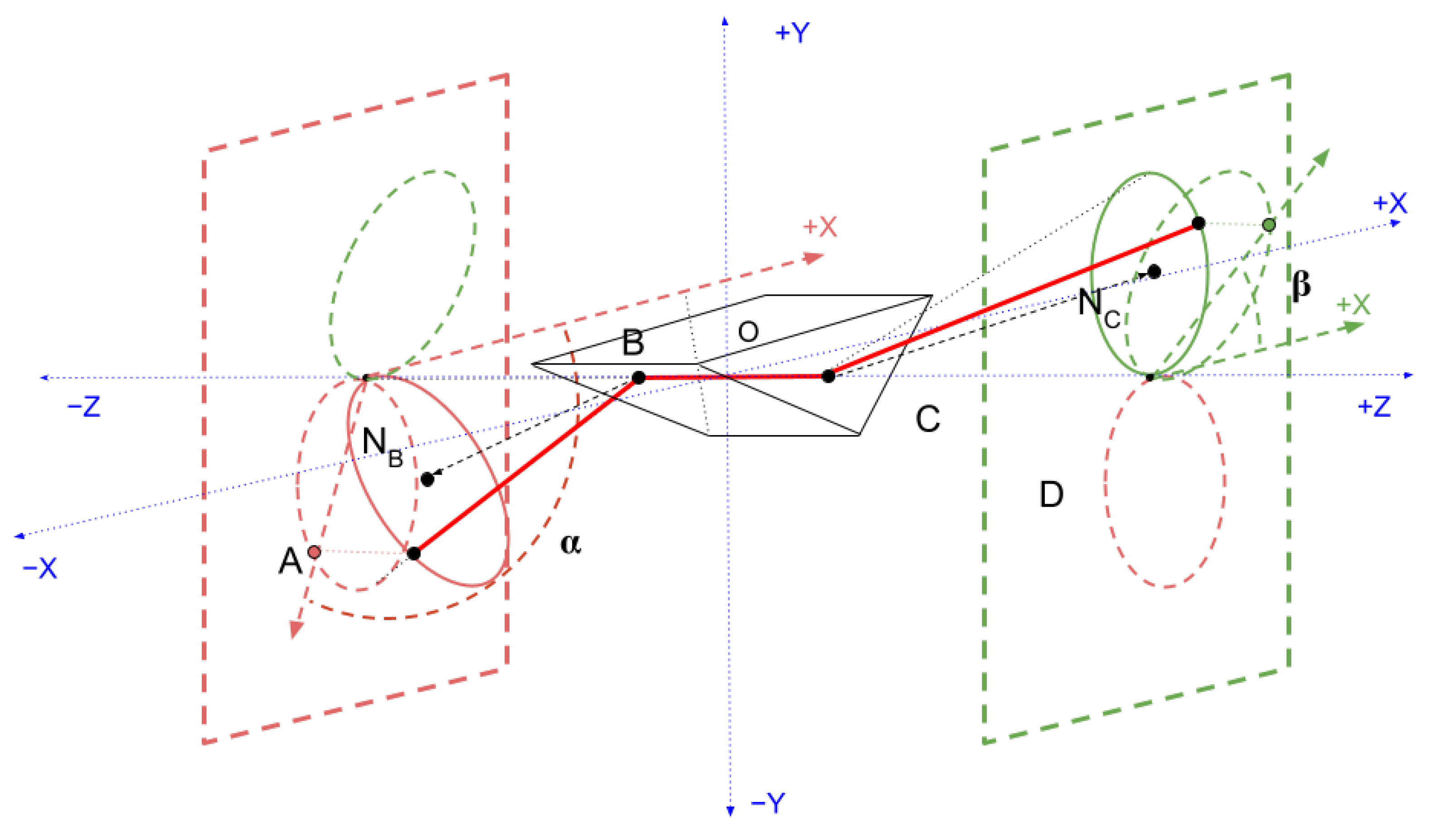
Proof. Figure 7 renders an arbitrary prism in balanced position. The
B joint is on the far-side face of the prism in the figure. As usual,
is measured against the face. The face normals are labeled
and
. They are drawn to projection planes orthogonal to the object axis, which is the
z-axis aligned as per our usual convention. The
face normal forms an angle
around the negative
z-axis, and the
face normal an angled
around the positive
z-axis.
Because this theorem is about finding a particular , let the function be the angle formed by the projection of the vector A and the origin with the X axis in the -plane. Let be the angle of the D projection. and are periodic on ranging between 0 and . The angles and are measured in the plane against the positive X axis.
Let and be the angles in between the A face-vector and B face-vectors, respectively, formed with the vector and , respectively. Unlike and , and are not confined to a plane, and describe a cone-like object as varies.
If , then one is greater than the other. Without loss of generality, assume . Then D moves in a cone about the face normal as is varied. The angle of the projection of D is , which varies as varies. The projection of both A and D move in circles potentially tilted to the z-axis, thereby forming ellipse-like figures in the projection planes.
By assumption, because , the ellipse formed by D as changes strictly contains the origin of the projection plane. Therefore, at least one of or has a range containing both 0 and , since the angle swept out by a point on the edge of this figure goes completely around the origin. Without loss of generality, let have a range including 0 and .
Both and are continuous functions, by the continuity of physical mechanisms and the composition of continuous functions.
Note that although the motion need not be proportional, the sign of the motion of is the opposite of the sign of the motion of as is varied.
Because varies between 0 and (although may not), and because moves in the opposite direction, by the Intermediate Value Theorem of real analysis, there is a where . Such a point produces a toroid-like figure (zero tightness).
Since can be moved in a complete circle (between 0 and ), there is always exactly one which places opposite (i.e., ). This is the flat case, which is the maximal extent of the segmented helix (that is, maximum tightness).
Now consider the case that
, as illustrated in
Figure 8.
In this case, the edges of the ellipses formed in the projection plane of both A and D intersect the z-axis, because there is always a that rotates the face about the face normally so that they cancel completely. By Theorem 3, this must occur at the same time on both sides, because the angle of the member with must equal the angle of the member with .
Note that the projected ellipses may occur in any relation to each other.
Figure 8 illustrates one circumstance in which the face normal vectors are pointing in approximately opposite directions. If the projections of the face normals are anti-parallel, they will be exactly opposite each other. In this case, the green (D) and red (A) projections will coincide at only one point; this is a straight line of a degenerate torus.
In an unbalanced position, the rate of change of
and
need not be proportional. However, if the entire figure is rotated into the conventional balanced configuration for any given
, then the rate of change of
will be exactly opposite
, as illustrated in
Figure 9. Let
and
be the angles formed with the negative
y-axis in the balanced configuration. By definition of balance about the
y-axis,
.
This means the intersection point of the two projected ellipses (which may be very close to the z-axis), will always be reached at exactly time (): . This intersection point in the balanced configuration is straight down; it is the point at which the projections are in the same plane (the plane of the z-axis), and at this point, the segmented helix is a toroid-like figure. Since there is always such an intersection point and can be moved through a full rotation, such a toroidal point can always be reached. If the face normals are precisely anti-parallel, this point will occur at the origin, and in that case will be a straight line, which is in a sense a degenerate torus-like figure.
Similarly, the objects can always be twisted to a point where
A and
D are pointing opposite each other as measured from the origin of the projection plane, so that
. This is always the “flat” or maximally extended point of maximum tightness. In the balanced convention, this occurs when the projection points are coincident with the
x-axis in the projection plane, as shown in
Figure 9. Because in this case
the A and D points are always (even in the first case of this proof) at equal angles to the
z-axis aligned object axis
, the
A and
D projection points move at the same speed (with respect to
), and they meet the
x-axis at the same
value.
Thus, when the absolute value of the face normals formed with the z-axis are equal, the objects can be smoothly twisted through a spectrum between the toroid-like figure (zero travel, or , and therefore minimum tightness), and the position of maximal travel. □
It would be more useful and elegant to have a formula for the twist that produces a torus as a function of the joint face normals, which is future work. Nonetheless, in the calculator page the that produces the minimum tightness (torus-like) and maximum tightness (zig-zag) to the nearest 360-degree is numerically calculated, with the labels Minimum Tightness τ and Maximum Tightness τ.
