
Dynamic Response of the Inertial Platform of the Laser ELI-NP Magurele-Bucharest Facility


 , , and
Abstract
:1. Introduction
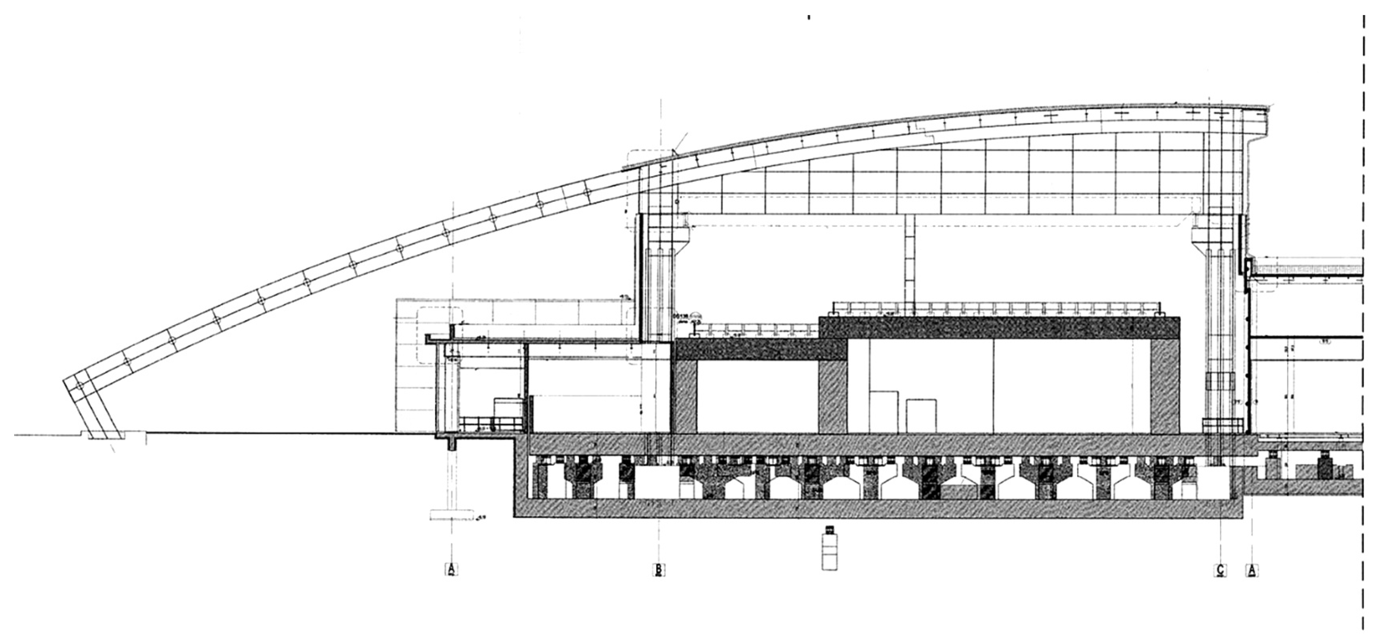
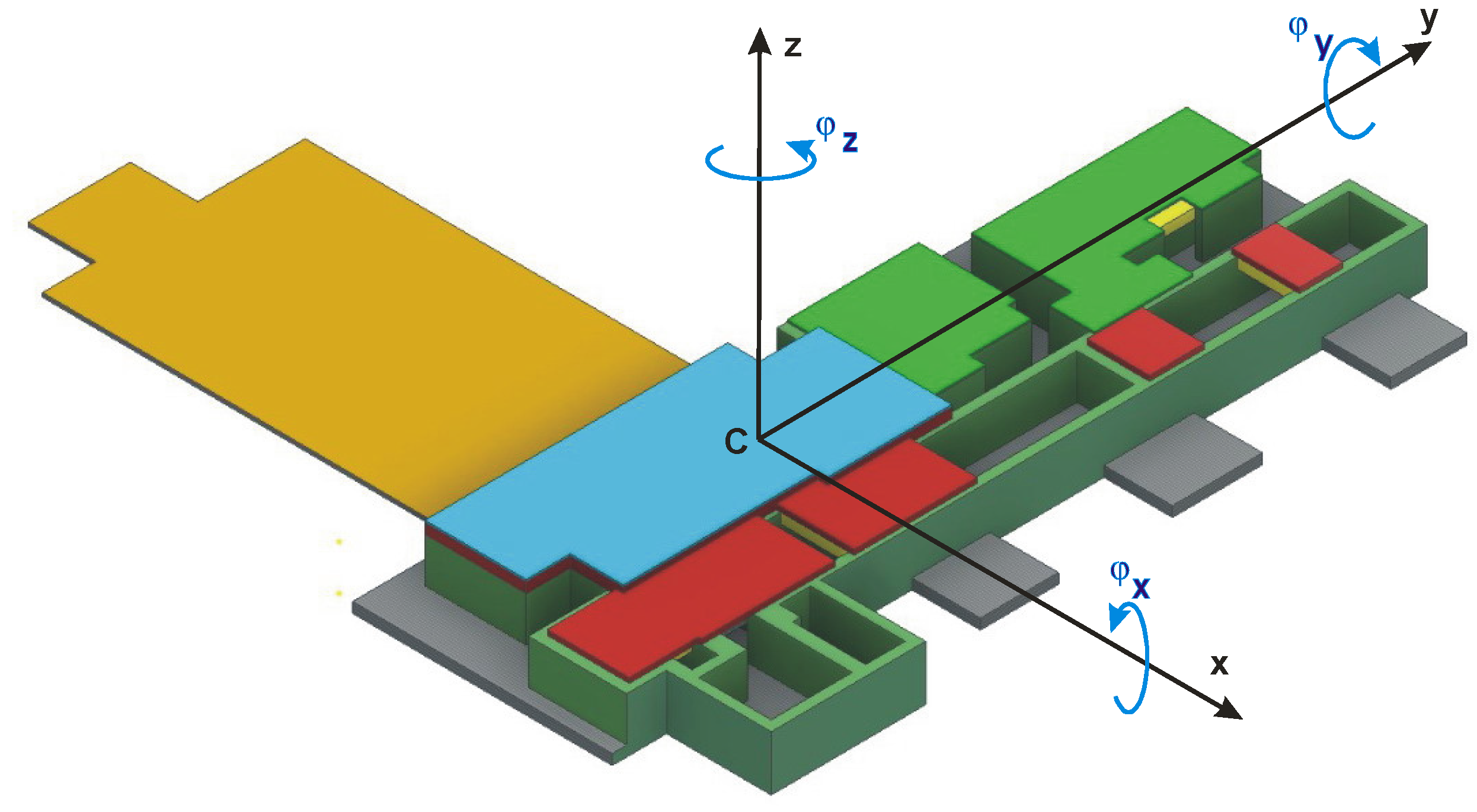
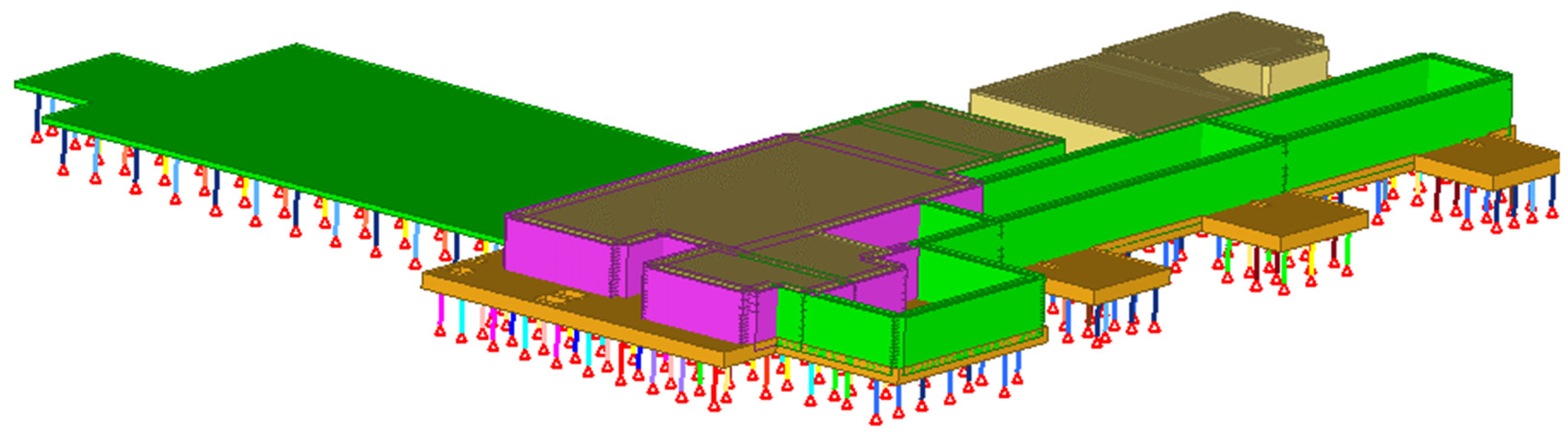
2. Materials and Methods
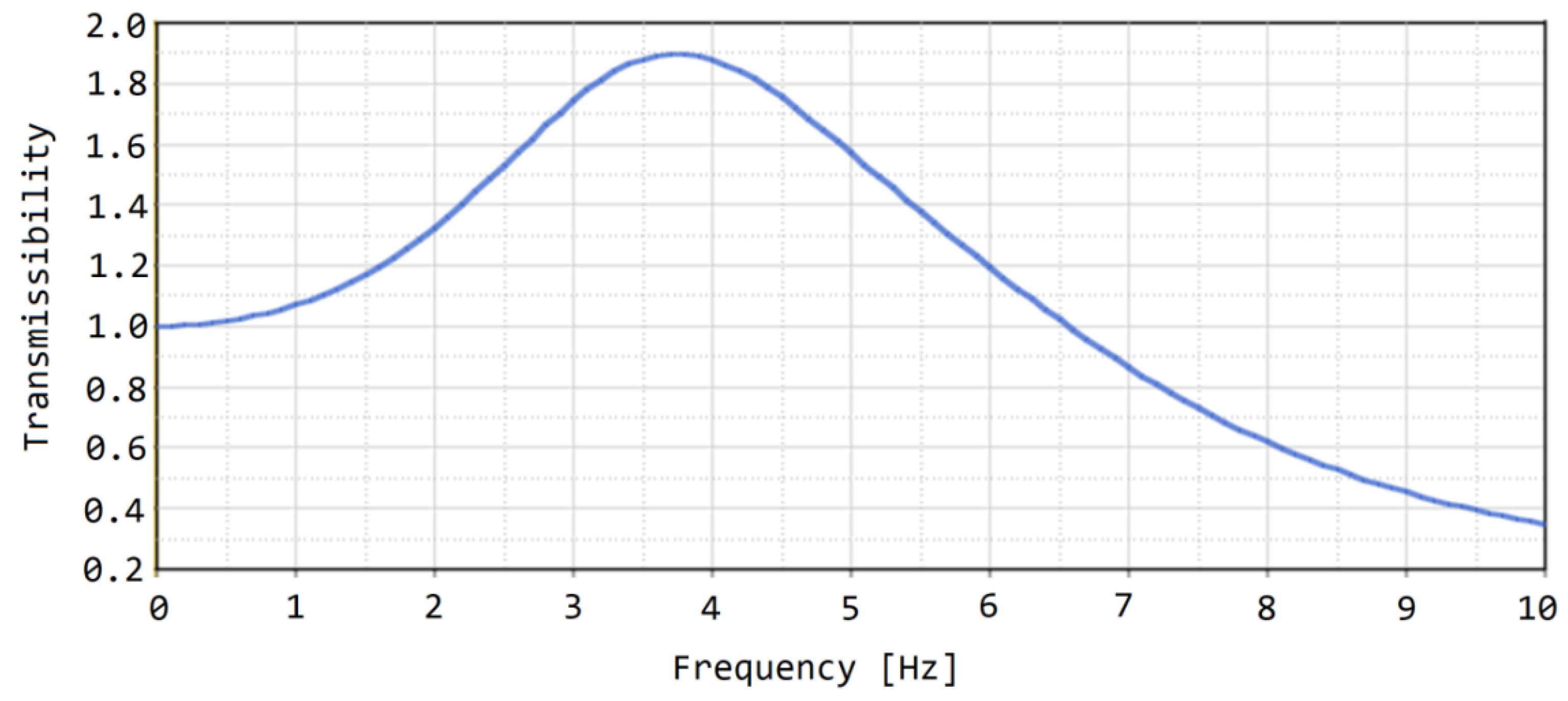
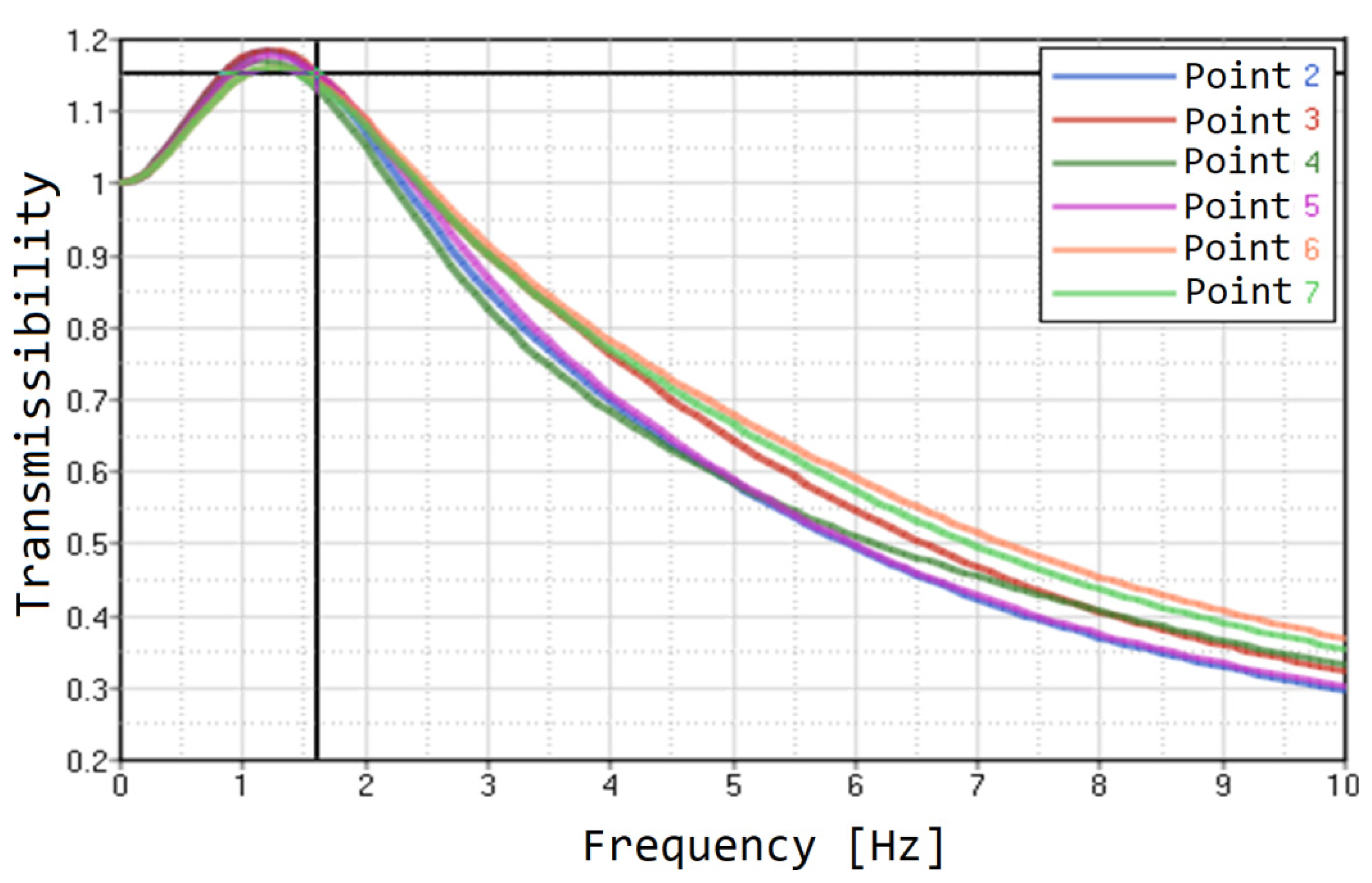
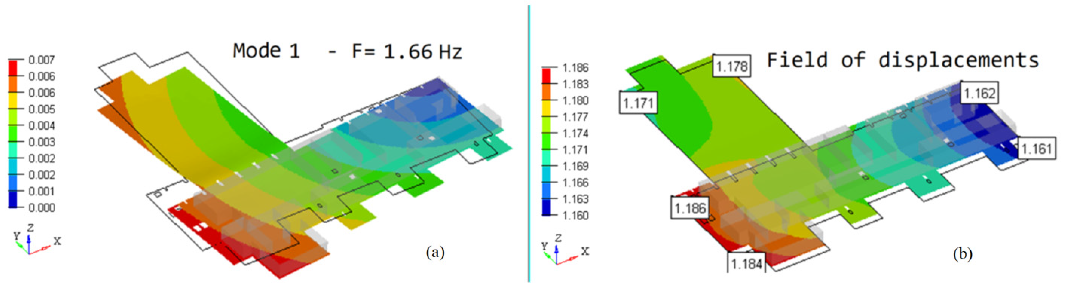
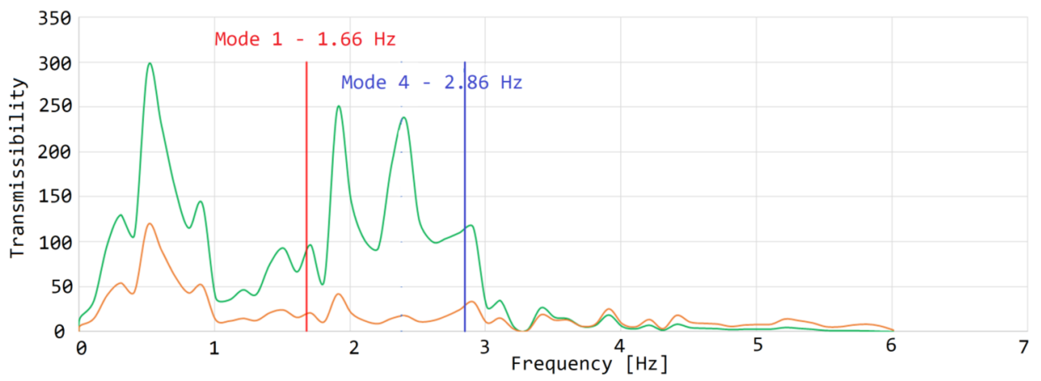
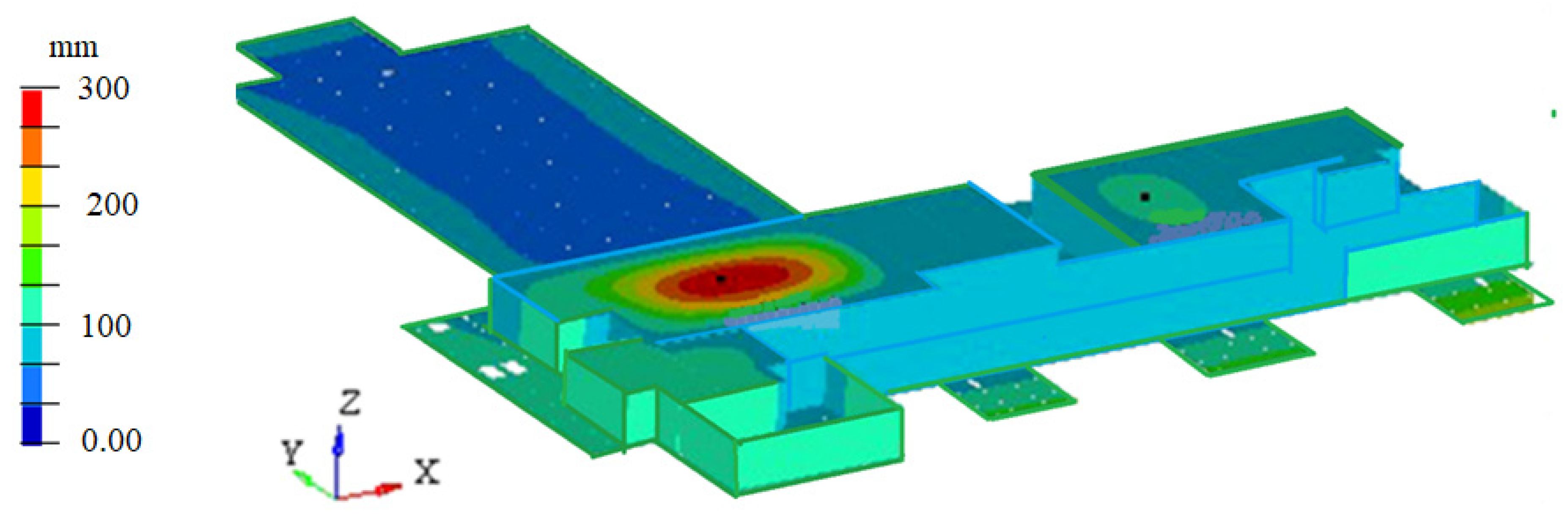
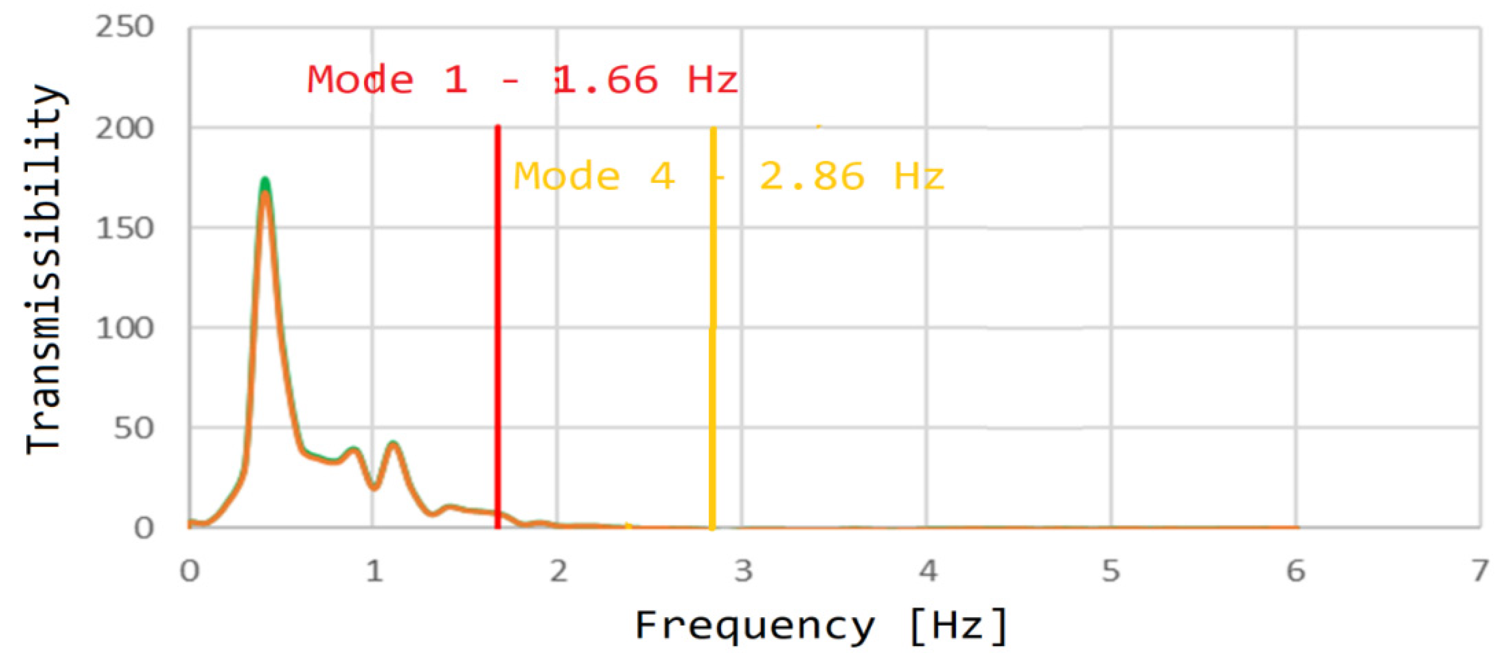
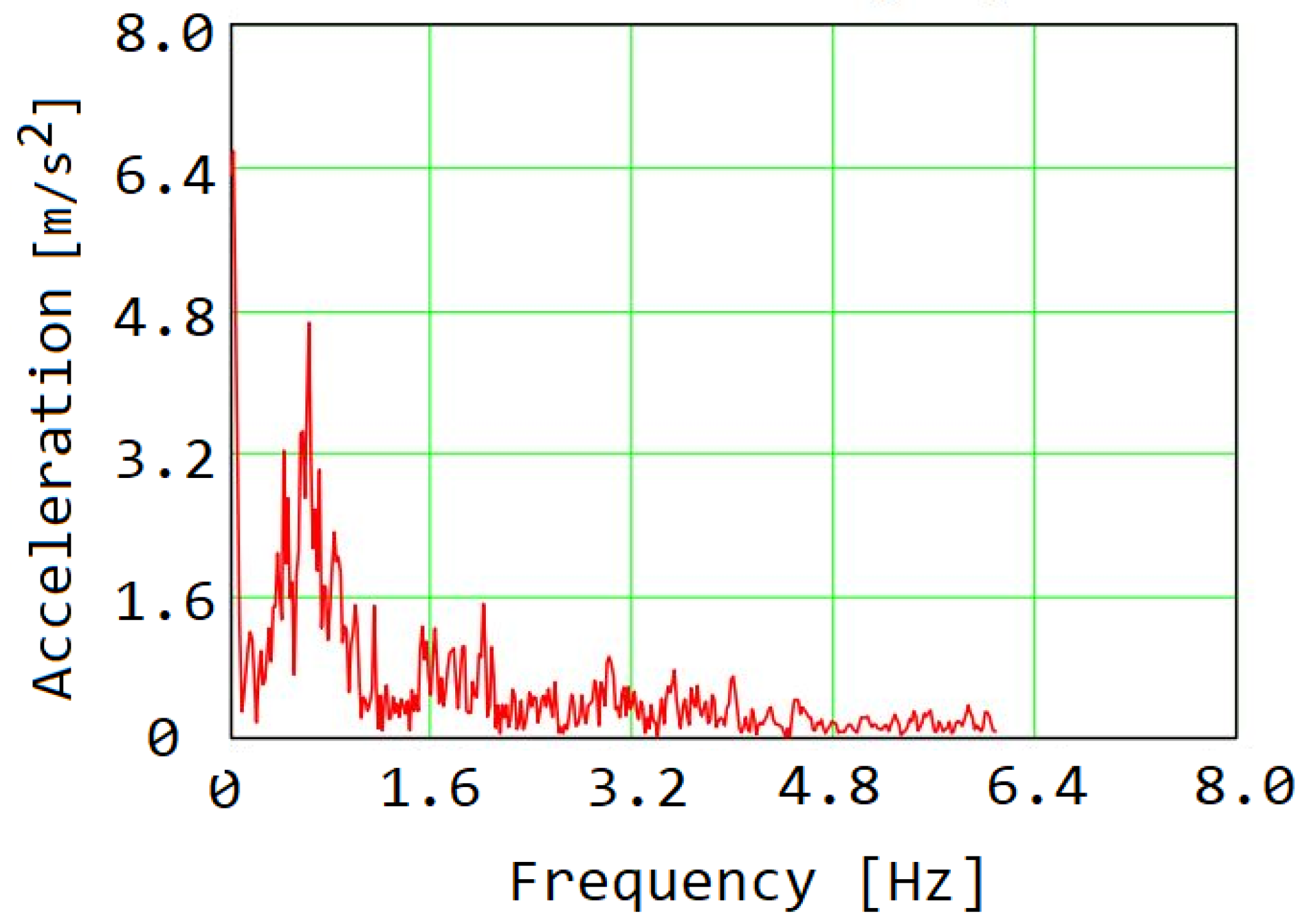
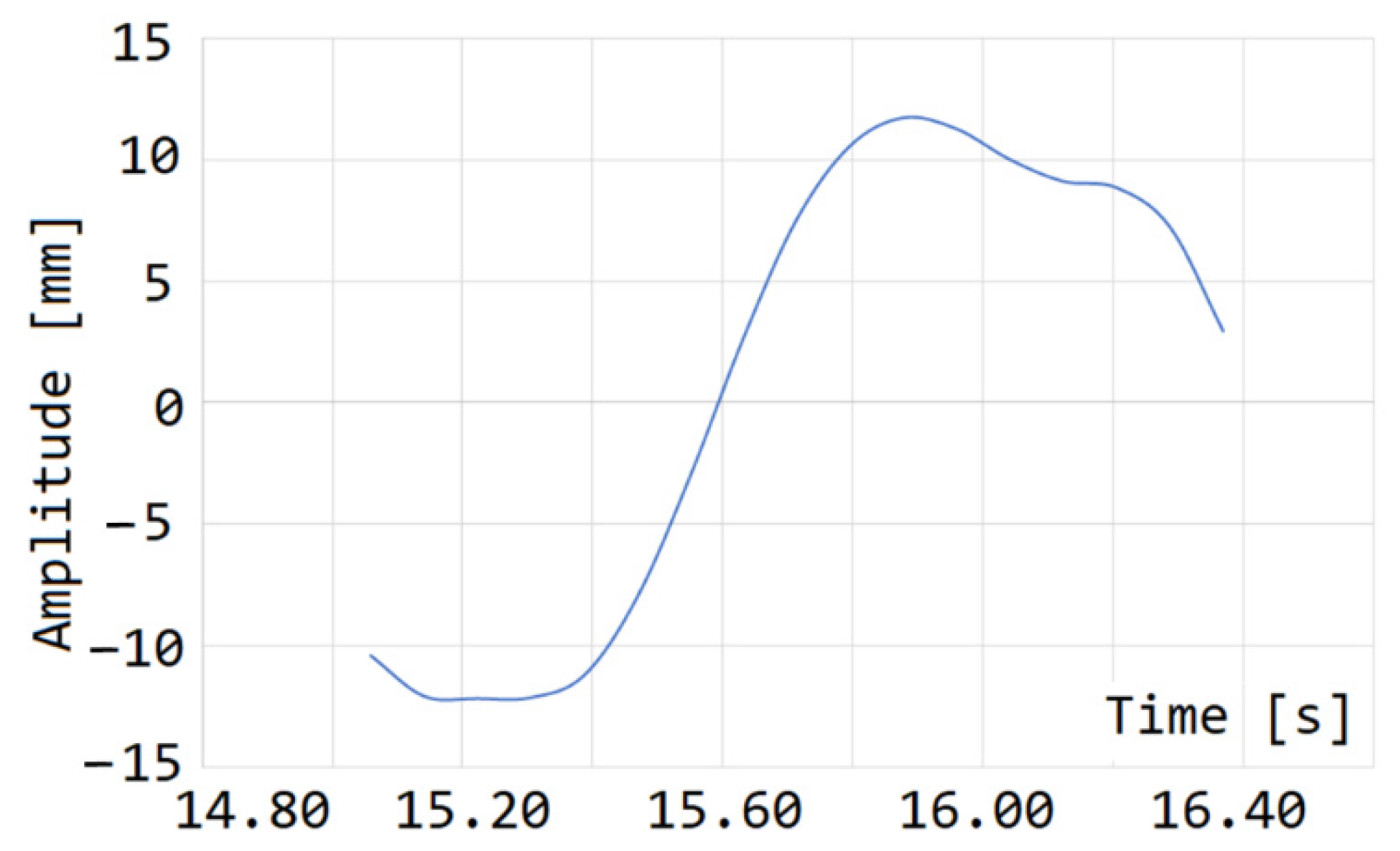
3. Results
4. Discussion and Conclusions
Author Contributions
Funding
Institutional Review Board Statement
Informed Consent Statement
Data Availability Statement
Conflicts of Interest
Appendix A

| Mode | Frequency | X-TRANS | Y-TRANS | Z-TRANS | X-ROTAT | Y-ROTAT | Z-ROTAT |
|---|---|---|---|---|---|---|---|
| 1 | 1.655 | 5.75 × 10³ | 3.32 × 10⁴ | 1.09 × 100 | 1.65 × 10¹¹ | 1.80 × 10¹⁰ | 1.72 × 10¹³ |
| 2 | 1.692 | 4.24 × 10⁴ | 8.96 × 10³ | 3.85 × 10⁻¹ | 6.19 × 10¹⁰ | 2.66 × 10¹¹ | 9.68 × 10¹³ |
| 3 | 1.781 | 3.48 × 10³ | 9.23 × 10³ | 2.60 × 100 | 3.53 × 10¹⁰ | 1.77 × 10⁹ | 1.39 × 10¹⁴ |
| 4 | 2.856 | 5.30 × 101 | 1.21 × 101 | 1.61 × 10⁴ | 1.37 × 10¹³ | 2.25 × 10¹² | 1.34 × 10¹¹ |
| 5 | 3.045 | 2.98 × 100 | 1.45 × 10² | 2.38 × 10⁴ | 3.12 × 10¹² | 1.24 × 10¹⁴ | 6.44 × 10¹¹ |
| 6 | 3.258 | 6.28 × 100 | 1.42 × 10² | 6.00 × 10³ | 1.56 × 10¹³ | 5.43 × 10¹³ | 1.96 × 10¹¹ |
| 7 | 3.381 | 2.58 × 10⁻² | 6.66 × 10⁻² | 2.38 × 101 | 6.63 × 10¹⁰ | 1.88 × 10¹⁰ | 1.14 × 10⁸ |
| 8 | 3.403 | 3.21 × 10⁻² | 3.81 × 10⁻¹ | 9.96 × 101 | 3.66 × 10¹⁰ | 8.25 × 10⁷ | 1.82 × 10⁹ |
| 9 | 3.412 | 2.76 × 100 | 2.23 × 100 | 8.72 × 101 | 1.34 × 10¹⁰ | 1.06 × 10¹³ | 1.07 × 10¹⁰ |
| 10 | 3.458 | 1.57 × 10⁻⁴ | 4.63 × 10⁻² | 1.82 × 10³ | 2.92 × 10¹² | 2.33 × 10¹² | 1.69 × 10⁸ |
| 11 | 3.603 | 7.88 × 10⁻³ | 3.45 × 10⁻² | 2.59 × 101 | 1.22 × 10⁹ | 8.55 × 10¹⁰ | 3.36 × 10⁷ |
| 12 | 3.668 | 1.11 × 100 | 2.72 × 100 | 5.29 × 10² | 6.86 × 10¹¹ | 2.53 × 10¹² | 2.99 × 10¹⁰ |
| 13 | 3.699 | 1.22 × 101 | 1.08 × 101 | 1.90 × 10³ | 2.36 × 10¹² | 1.49 × 10¹³ | 2.42 × 10¹¹ |
| 14 | 3.933 | 9.37 × 10⁻³ | 5.80 × 10⁻² | 6.87 × 10² | 1.16 × 10¹² | 8.99 × 10¹¹ | 1.20 × 10⁶ |
| 15 | 4.067 | 1.19 × 10⁻³ | 2.95 × 10⁻² | 1.47 × 10² | 1.36 × 10¹¹ | 3.18 × 10¹¹ | 3.61 × 10⁷ |
| 16 | 4.162 | 2.42 × 10⁻¹ | 2.13 × 10⁻¹ | 1.77 × 10² | 7.56 × 10¹⁰ | 2.09 × 10¹¹ | 3.44 × 10⁶ |
| 17 | 4.215 | 2.04 × 101 | 1.36 × 100 | 5.61 × 101 | 8.73 × 10¹⁰ | 8.32 × 10¹¹ | 1.82 × 10⁹ |
| 18 | 4.582 | 8.37 × 10⁻³ | 4.80 × 10⁻² | 9.26 × 101 | 3.61 × 10¹¹ | 1.09 × 10¹¹ | 3.22 × 10⁷ |
| 19 | 4.857 | 2.67 × 10⁻³ | 4.72 × 10⁻³ | 5.00 × 100 | 2.49 × 10⁹ | 8.23 × 10⁹ | 2.01 × 10⁸ |
| 20 | 4.987 | 2.27 × 10⁻¹ | 1.27 × 10⁻¹ | 1.28 × 101 | 6.55 × 10⁹ | 2.06 × 10¹⁰ | 8.54 × 10⁷ |
| 21 | 5.121 | 6.68 × 10⁻³ | 7.52 × 10⁻¹ | 2.49 × 101 | 2.31 × 10¹⁰ | 8.04 × 10¹⁰ | 8.82 × 10⁹ |
| 22 | 5.245 | 2.61 × 100 | 1.08 × 10⁻⁴ | 1.19 × 101 | 5.47 × 10⁷ | 3.04 × 10¹⁰ | 7.55 × 10⁹ |
| 23 | 5.443 | 1.67 × 10⁻³ | 4.39 × 10⁻³ | 4.88 × 100 | 2.43 × 10¹⁰ | 2.06 × 10¹⁰ | 1.40 × 10⁷ |
| 24 | 5.614 | 5.90 × 10⁻⁴ | 5.20 × 10⁻³ | 4.47 × 101 | 1.39 × 10¹¹ | 4.28 × 10¹⁰ | 5.69 × 10⁶ |
| 25 | 5.773 | 1.91 × 10⁻² | 8.44 × 10⁻⁴ | 7.95 × 10⁻¹ | 5.89 × 10⁷ | 5.40 × 10⁹ | 1.59 × 10⁷ |
| 26 | 6.05 | 1.75 × 10⁻² | 1.34 × 10⁻¹ | 3.56 × 100 | 5.68 × 10⁸ | 1.95 × 10⁹ | 2.26 × 10⁵ |
| 27 | 6.312 | 1.10 × 10⁻² | 2.96 × 10⁻² | 3.40 × 10⁻¹ | 7.04 × 10⁹ | 1.96 × 10⁷ | 5.60 × 10⁶ |
| 28 | 6.372 | 8.57 × 10⁻² | 5.78 × 10⁻¹ | 6.98 × 100 | 6.71 × 10⁹ | 1.02 × 10¹⁰ | 1.95 × 10⁹ |
| 29 | 6.517 | 2.08 × 10⁻² | 1.27 × 10⁻² | 7.21 × 100 | 7.90 × 10⁷ | 1.43 × 10¹⁰ | 5.45 × 10⁸ |
| 30 | 6.805 | 8.63 × 10⁻³ | 3.70 × 10⁻³ | 1.91 × 101 | 4.05 × 10⁹ | 3.04 × 10¹⁰ | 2.88 × 10⁸ |
| SUBCASE | TOTAL | 5.17 × 10⁴ | 5.17 × 10⁴ | 5.17 × 10⁴ | 4.08 × 10¹³ | 2.14 × 10¹⁴ | 2.54 × 10¹⁴ |
| Mode | Frequency | X-TRANS | Y-TRANS | Z-TRANS | X-ROTAT | Y-ROTAT | Z-ROTAT |
|---|---|---|---|---|---|---|---|
| 1 | 1.655 | 11.12% | 64.24% | 0.00% | 0.41% | 0.01% | 6.79% |
| 2 | 1.692 | 81.94% | 17.31% | 0.00% | 0.15% | 0.12% | 38.12% |
| 3 | 1.781 | 6.73% | 17.84% | 0.01% | 0.09% | 0.00% | 54.57% |
| 4 | 2.856 | 0.10% | 0.02% | 31.06% | 33.59% | 1.05% | 0.05% |
| 5 | 3.045 | 0.01% | 0.28% | 46.12% | 7.64% | 57.93% | 0.25% |
| 6 | 3.258 | 0.01% | 0.27% | 11.61% | 38.22% | 25.41% | 0.08% |
| 7 | 3.381 | 0.00% | 0.00% | 0.05% | 0.16% | 0.01% | 0.00% |
| 8 | 3.403 | 0.00% | 0.00% | 0.19% | 0.09% | 0.00% | 0.00% |
| 9 | 3.412 | 0.01% | 0.00% | 0.17% | 0.03% | 4.94% | 0.00% |
| 10 | 3.458 | 0.00% | 0.00% | 3.51% | 7.16% | 1.09% | 0.00% |
| 11 | 3.603 | 0.00% | 0.00% | 0.05% | 0.00% | 0.04% | 0.00% |
| 12 | 3.668 | 0.00% | 0.01% | 1.02% | 1.68% | 1.18% | 0.01% |
| 13 | 3.699 | 0.02% | 0.02% | 3.68% | 5.79% | 6.97% | 0.10% |
| 14 | 3.933 | 0.00% | 0.00% | 1.33% | 2.85% | 0.42% | 0.00% |
| 15 | 4.067 | 0.00% | 0.00% | 0.28% | 0.33% | 0.15% | 0.00% |
| 16 | 4.162 | 0.00% | 0.00% | 0.34% | 0.19% | 0.10% | 0.00% |
| 17 | 4.215 | 0.04% | 0.00% | 0.11% | 0.21% | 0.39% | 0.00% |
| 18 | 4.582 | 0.00% | 0.00% | 0.18% | 0.88% | 0.05% | 0.00% |
| 19 | 4.857 | 0.00% | 0.00% | 0.01% | 0.01% | 0.00% | 0.00% |
| 20 | 4.987 | 0.00% | 0.00% | 0.02% | 0.02% | 0.01% | 0.00% |
| 21 | 5.121 | 0.00% | 0.00% | 0.05% | 0.06% | 0.04% | 0.00% |
| 22 | 5.245 | 0.01% | 0.00% | 0.02% | 0.00% | 0.01% | 0.00% |
| 23 | 5.443 | 0.00% | 0.00% | 0.01% | 0.06% | 0.01% | 0.00% |
| 24 | 5.614 | 0.00% | 0.00% | 0.09% | 0.34% | 0.02% | 0.00% |
| 25 | 5.773 | 0.00% | 0.00% | 0.00% | 0.00% | 0.00% | 0.00% |
| 26 | 6.05 | 0.00% | 0.00% | 0.01% | 0.00% | 0.00% | 0.00% |
| 27 | 6.312 | 0.00% | 0.00% | 0.00% | 0.02% | 0.00% | 0.00% |
| 28 | 6.372 | 0.00% | 0.00% | 0.01% | 0.02% | 0.00% | 0.00% |
| 29 | 6.517 | 0.00% | 0.00% | 0.01% | 0.00% | 0.01% | 0.00% |
| 30 | 6.805 | 0.00% | 0.00% | 0.04% | 0.01% | 0.01% | 0.00% |
| SUBCASE | TOTAL | 1.00 ×100 | 1.00 ×100 | 1.00 ×100 | 1.00 ×100 | 1.00 ×100 | 1.00 ×100 |
References
- The White Book of ELI Nuclear Physics Bucharest-Magurele, Romania. Available online: http://www.eli-np.ro/whitebook.php (accessed on 1 March 2022).
- Serafini, L. EuroGammaS Proposal for the ELI-NP Gamma beam System. Technical Design Report. July 2014. Available online: https://arxiv.org/ftp/arxiv/papers/1407/1407.3669.pdf (accessed on 1 March 2022).
- Habs, D.; Tajima, T.; Zamfir, V. Extreme Light Infrastructure–Nuclear Physics (ELI–NP): New Horizons for Photon Physics in Europe. Nucl. Phys. News 2011, 21, 23–29. [Google Scholar] [CrossRef]
- Zamfir, N.V. Nuclear Physics with 10 PW laser beams at Extreme Light Infrastructure—Nuclear Physics (ELI-NP). Eur. Phys. J. Spéc. Top. 2014, 223, 1221–1227. [Google Scholar] [CrossRef]
- Welch, J. Ground Vibration and Siting of the Cryogenics Facility for Cornell ERL Prototype. Technical Design Report. Available online: https://www.classe.cornell.edu/public/ERL/2002/ERL02-3/ERL02-3.pdf (accessed on 1 March 2022).
- Arnold, C. Seismic Design & Devices for Detaching Building from the Ground. Archit. AIA J. 1987, 76, 64–67. [Google Scholar]
- Tarics, A.G. Base-Isolation—A New Strategy for Earthquake Protection of Buildings. J. Archit. Plan. Res. 1987, 4, 64–76. [Google Scholar]
- Bratu, P.; Goanta, A.M.; Dragan, N.; Vlase, S.; Itu, C.; Nicolae, G.L.; Iacovescu, S. Dynamic Behavior of the Inertial Platform Related to the Research Facility Building Laser and Gamma at ELI-NP Bucharest. Symmetry 2022, 14, 831. [Google Scholar] [CrossRef]
- Teramoto, T. Recent Current of Noise Isolation and Seismic Control-System for Building Structure. Tetsu Hagane J. Iron Steel Inst. Jpn. 1987, 73, S348. [Google Scholar]
- Jiang, M.; Rui, X.; Zhu, W.; Yang, F.; Zhang, Y. Optimal design of 6-DOF vibration isolation platform based on transfer matrix method for multibody systems. Acta Mech. Sin. 2020, 37, 127–137. [Google Scholar] [CrossRef]
- Han, P.; Wang, T.; Wang, D.H. Modeling and control of a Stewart platform based six-axis hybrid vibration isolation system. In Proceedings of the 2008 7th World Congress on Intelligent Control and Automation, Chongqing, China, 25–27 June 2008; Volume 1–23, pp. 1613–1618. [Google Scholar] [CrossRef]
- Geng, Z.; Haynes, L.S. Six-degree-of-freedom active vibration isolation using a stewart platform mechanism. J. Robot. Syst. 1993, 10, 725–744. [Google Scholar] [CrossRef]
- Liu, L.; Wang, B. Development of Stewart platforms for active vibration isolation and precision pointing. In Proceedings of the International Conference on Smart Materials and Nanotechnology in Engineering, Harbin, China, 1–4 July 2007. [Google Scholar]
- Ma, R.; Bi, K.; Hao, H. Heave motion mitigation of semi-submersible platform using inerter-based vibration isolation system (IVIS). Eng. Struct. 2020, 219, 110833. [Google Scholar] [CrossRef]
- Xie, X.; Diao, J.; Xu, Y.; Zhang, Z. Performance of a low-frequency hybrid vibration isolation platform for vibration-sensitive devices. J. Low Freq. Noise Vib. Act. Control 2018, 37, 1164–1175. [Google Scholar] [CrossRef] [Green Version]
- Xu, Z.-D.; Xu, F.-H.; Chen, X. Vibration suppression on a platform by using vibration isolation and mitigation devices. Nonlinear Dyn. 2015, 83, 1341–1353. [Google Scholar] [CrossRef]
- Assmann, R.; Jeanneret, B.; Verdier, A.; Vos, L.; Wildner, E.; Zimmermann, F.; Brinkmann, R.; Montag, C.; Reyzl, I.; Walker, N.; et al. Stability considerations for final focus systems of future linear collinder. In Proceedings of the 7th European Conference, EPAC 2000, Vienna, Austria, 26–30 June 2000; p. 447. [Google Scholar]
- Bolzon, B. Etude des Vibrations et de la Stabilisation à L’échelle Sous-Nanométrique des Doublets Finaux d’un Collisionneur Linéaire. Ph.D. Thesis, Université Chambery Annecy de Savoie, Chambéry, France, 2007. [Google Scholar]
- A Multi-Tev Linear Collider Based on Clic Technology, Conceptual Design Report. KEK Report 2012-1, Geneva. 2012. Available online: http://cds.cern.ch/record/1601966/files/ILCTDR-Volume_1.pdf (accessed on 16 June 2022).
- Nazreen, M.S.; Mohamed, R.N.; Ab Kadir, M.A.; Azillah, N.; Shukri, N.A.; Mansor, S.; Zamri, F. Characterization of lightweight concrete made of palm oil clinker aggregates. MATEC Web Conf. 2018, 250, 03002. [Google Scholar] [CrossRef]
- Gul, M.; Bashir, A.; Naqash, J.A. Study of Modulus of Elasticity of Steel Fiber Reinforced Concrete. Int. J. Eng. Adv. Technol. 2014, 3, 24–30. Available online: https://www.ijeat.org/wp-content/uploads/papers/v3i4/D2995043414.pdf (accessed on 16 June 2022).
- Yusof, M.A.; Nor, N.M.; Fauzi, M.; Zain, M.; Ismail, A.; Sohaimi, A.; Zaidi, A.M. Mechanical Properties of Hybrid Steel Fibre Reinforced Concrete with Different Aspect Ratio. Aust. J. Basic Appl. Sci. 2011, 5, 159–166. [Google Scholar]
- Eurocode Applied. Available online: https://eurocodeapplied.com/design/en1992/concrete-design-properties (accessed on 21 December 2020).
- Marin, M. Some basic theorems in elastostatics of micropolar materials with voids. J. Comput. Appl. Math. 1996, 70, 115–126. [Google Scholar] [CrossRef] [Green Version]
- Itu, C.; Öchsner, A.; Vlase, S.; Marin, M.I. Improved rigidity of composite circular plates through radial ribs. Proc. Inst. Mech. Eng. Part L J. Mater. Des. Appl. 2019, 233, 1585–1593. [Google Scholar] [CrossRef]
- Itu, C.; Bratu, P.; Borza, P.N.; Vlase, S.; Lixandroiu, D. Design and Analysis of Inertial Platform Insulation of the ELI-NP Project of Laser and Gamma Beam Systems. Symmetry 2020, 12, 1972. [Google Scholar] [CrossRef]
- Vlase, S.; Negrean, I.; Marin, M.; Scutaru, M.L. Energy of Accelerations Used to Obtain the Motion Equations of a Three- Dimensional Finite Element. Symmetry 2020, 12, 321. [Google Scholar] [CrossRef] [Green Version]
- Rades, M. Mechanical Vibration, II, Structural Dynamics Modeling; Printech Publishing House: Bangalore, India, 2010. [Google Scholar]
- Vlase, S.; Marin, M.; Öchsner, A.; Scutaru, M.L. Motion equation for a flexible one-dimensional element used in the dynamical analysis of a multibody system. Contin. Mech. Thermodyn. 2019, 31, 715–724. [Google Scholar] [CrossRef]
- Scutaru, M.L.; Vlase, S.; Marin, M. New analytical method based on dynamic response of planar mechanical elastic systems. Bound. Value Probl. 2020, 2020, 104. [Google Scholar] [CrossRef]
- Vlase, S.; Teodorescu, P.P.; Itu, C.; Scutaru, M.L. Elasto-Dynamics of a Solid with a General “Rigid” Motion using FEM Model. Rom. J. Phys. 2013, 58, 882–892. [Google Scholar]
- Hu, R.; Iwamoto, S.; Feng, L.; Ju, S.; Hu, S.; Ohnishi, M.; Nagai, N.; Hirakawa, K.; Shiomi, J. Machine-Learning-Optimized Aperiodic Superlattice Minimizes Coherent Phonon Heat Conduction. Phys. Rev. X 2020, 10, 021050. [Google Scholar] [CrossRef]
- Artoos, K.; Petit-Jean-Genaz, C.; Schaa, V.R.W.; Shirai, T.; Shirakaw, A. In Proceedings of the 1st International Particle Accelerator Conference (IPAC’10), Kyoto, Japan, 23–28 May 2010; Volume 16, pp. 1274–1276.


| No. of Mode | Frequency (Hz) | No. of Mode | Frequency (Hz) |
|---|---|---|---|
| 1 | 1.655 | 16 | 4.162 |
| 2 | 1.692 | 17 | 4.215 |
| 3 | 1.781 | 18 | 4.582 |
| 4 | 2.856 | 19 | 4.857 |
| 5 | 3.045 | 20 | 4.987 |
| 6 | 3.258 | 21 | 5.121 |
| 7 | 3.381 | 22 | 5.245 |
| 8 | 3.403 | 23 | 5.443 |
| 9 | 3.412 | 24 | 5.614 |
| 10 | 3.458 | 25 | 5.773 |
| 11 | 3.603 | 26 | 6.051 |
| 12 | 3.668 | 27 | 6.312 |
| 13 | 3.699 | 28 | 6.372 |
| 14 | 3.933 | 29 | 6.517 |
| 15 | 4.067 | 30 | 6.805 |
| Mode 1 | Mode 2 | Mode 3 |
  |  |  |
| Mode 4 | Mode 5 | Mode 6 |
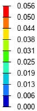  | 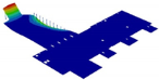 |  |
| Mode 7 | Mode 8 | Mode 9 |
  | 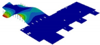 | 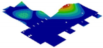 |
| Mode 10 | Mode 11 | Mode 12 |
  |  |  |
Publisher’s Note: MDPI stays neutral with regard to jurisdictional claims in published maps and institutional affiliations. |
© 2022 by the authors. Licensee MDPI, Basel, Switzerland. This article is an open access article distributed under the terms and conditions of the Creative Commons Attribution (CC BY) license (https://creativecommons.org/licenses/by/4.0/).
Share and Cite
Itu, C.; Bratu, P.; Dragan, N.; Goanță, A.; Nicolae, G.L.; Nițu, M.C.; Borza, P.N.; Vlase, S. Dynamic Response of the Inertial Platform of the Laser ELI-NP Magurele-Bucharest Facility. Mathematics 2022, 10, 2104. https://doi.org/10.3390/math10122104
Itu C, Bratu P, Dragan N, Goanță A, Nicolae GL, Nițu MC, Borza PN, Vlase S. Dynamic Response of the Inertial Platform of the Laser ELI-NP Magurele-Bucharest Facility. Mathematics. 2022; 10(12):2104. https://doi.org/10.3390/math10122104
Chicago/Turabian StyleItu, Calin, Polidor Bratu, Nicusor Dragan, Adrian Goanță, George Lucian Nicolae, Marilena Cristina Nițu, Paul Nicolae Borza, and Sorin Vlase. 2022. "Dynamic Response of the Inertial Platform of the Laser ELI-NP Magurele-Bucharest Facility" Mathematics 10, no. 12: 2104. https://doi.org/10.3390/math10122104
APA StyleItu, C., Bratu, P., Dragan, N., Goanță, A., Nicolae, G. L., Nițu, M. C., Borza, P. N., & Vlase, S. (2022). Dynamic Response of the Inertial Platform of the Laser ELI-NP Magurele-Bucharest Facility. Mathematics, 10(12), 2104. https://doi.org/10.3390/math10122104