1. Introduction
Most engineering subjects require spending considerable time in a laboratory class to gain a practical and deeper understanding of the subject. In the past, most laboratory classes were conducted in hardware laboratories. This implied certain concerns regarding learning and utilization. Because of the limitations of the hardware involved, most experiments were conducted by a group of students. Students, therefore, may not have the chance to conduct each step of the experiment. The facilities, such as space and supporting staff, may not able to cope with all students if each student is provided with their own setup. If the laboratory could be run 24 h a day or 7 days a week (24/7), more students could enjoy learning, but each hardware laboratory class, especially those in the field of engineering, needs supervision. A typical minimum requirement of a staff to student ratio is 1:10 in most laboratories. This imposes further difficulties for long operations, the organization of manpower, and safety.
1.1. Virtual Laboratory
The alternative method is to use a virtual laboratory, which is actually a remote-controlled experiment. Students can control the experimental setup from anywhere in the world via the internet. They just log into the system and control the step in the experimental procedure. For electrical engineering, virtual laboratories enhance safety, because incorrect wiring connection is not allowed. The virtual laboratory should be programmed to take care of each step of the experiments so that students can ensure that all operations are within the safety limits; when this is not the case, a warning message appears. Advice and circuit configurations are also provided [
1].
Virtual laboratories are not new. They can assist students throughout entire experiments with a preset limit. This will also reduce the time spent by students, and students can also keep more closely to the timeline of their laboratory classes. Virtual laboratories using computer simulations exist, e.g., Matlab [
2], to control an electromagnetic experiment. Simulations using Java to experiment on machines have also been reported [
3]. Setup for high school physics laboratory is also present [
4] using the Matlab web server with HTML and m-files. Emulation-based virtual experiments for control engineering [
5] offer a low-cost solution for laboratory setups. A virtual laboratory with video game characteristics is implemented in 3D to make the experiment more interesting to the students [
6]. A competition/games method [
7] that comprises an e-education element could also speed up the learning process and would be suitable for lifelong education.
Electrical machines, especially those used in the study of magnetic B–H fields, are complicated. The use of modeling for 2D simulations of microwave fields [
8] has been reported. Deep understanding of the field behavior and the use of electromagnetic compatibility instruments such as network analyzers, spectra, and oscilloscopes is made possible. The author of [
9] reported a guided experiment to study the magnetic properties of electrical machines. One of the outstanding advantages of the virtual laboratory is the sharing of facilities among institutions. The author of [
10] reported a learning management system (LMS) which offers this feature. Further, chatrooms and forums are included.
1.2. Related Work
In general, virtual laboratories are easy to implement. Computer-aided design and manufacturing tutorials for educating engineering students [
11] are necessary. However, most existing virtual laboratories comprise computerized tuition or simulations. The author of [
12] described circuit analyses using a tutoring method; this allows students to decide which actions could validate the analysis. Reference [
13] is a study of rigid body mechanics for slip-steered vehicles and other transportation systems. To learn the field-programmable gate array (FPGA), the author of [
14] show how to create a prototype of a circuit design within the framework of an FPGA. The virtual laboratory is a great method for instrumentation learning [
15]. References [
16,
17,
18] are examples in teaching fuzzy logic control circuits, general electric circuits, and motors. The author of [
18] showed the successful development of a virtual laboratory for students in the US to access setups in Japan [
18]. Overall, it has been confirmed that virtual laboratories improve students’ learning through much easier, remotely controlled assessments [
19,
20,
21]. The use of Industry 4.0 for internet teaching has been reported for undergraduate final year projects [
22].
A qualified experiment should comprise a remote-controlled setup rather than just a computer simulation or emulation. A simple device characterization experiment is described in [
23] for a simple solid-state study. A photonics experiment using a VPEN (virtual photonics experiments network) [
24] is another such example. However, most reported virtual experiments are either computer simulations or simple remote-controlled experiments.
For physics and power engineering, virtual reality or 3D virtual environments have been extensively reported. Reference [
25] is an example of the development of power calculations for a renewable energy solar system. The author of [
26] discussed the study of power train platforms using virtual tools as well as real hardware. These initiatives were designed in a manner akin to virtual reality to give users a 3D experience, although their purpose is not directly the teaching of hardware laboratory skills [
27]. Therefore, it is interesting to explore learning in a hardware laboratory using different virtual reality approaches. In addition to computer simulations, a remote-control alternative is to be considered.
2. The Power Electronics Virtual Laboratory
In electrical engineering, power electronics courses require substantial hardware-based learning, which includes various experiments. In the past, only computer simulations such as circuit simulations or simple remote-controlled experiments for power device tests were used, but today, these are insufficient.
Usually, power electronics [
28,
29] experiments relate to power circuits, input power, output power load, and control methods through the control of computers. Each of the waveforms in voltage, current, and signal needs to be measured and adjusted. Sufficient power levels such as 100 W are required in the test so students can fully experience electric power processing. Therefore, good precaution, safety, and a controlled environment are needed.
The virtual power electronics laboratory (VPEL) is an internet learning system founded by the Department of Electrical Engineering at the Hong Kong Polytechnic University (PolyU). VPEL is the first power electronics virtual laboratory based in Hong Kong. It allows university students to access VPEL and is intended to give access to Pearl-River Delta universities for the VPEL training. VPEL offers:
Quality web-enabled lectures and laboratory experiments designed and developed specifically for electrical engineering teaching;
Robust learning experiences under a safe electrical environment to conduct experiments;
Clear instruction and an excellent pace for guiding students to conduct the experiment without supporting staff.
VPEL consists of three major components: real-time actual laboratory experiments, web teaching, and web-based simulations. Web-based interactive education is a very important trend that can function as teaching material. Using LabVIEW from National Instruments [
30,
31] as well as typical web site software including JavaScript, HTML, and Flash, it is possible to conduct and monitor the experiments remotely. In the teaching of power electronics, students’ hands-on training is equally important to theoretical learning. This system will lead to the earliest attempt for the development of a power electronics virtual laboratory.
To set up a proper hardware experiment a laboratory is a must for all electrical engineering. Investment in hardware and experimental facilities for electrical engineering, especially power electronics, is relatively high, because it requires power tests and complicated procedures for the laboratory staff and students that limit rapid expansion of the facility to solve the difficulty [
19,
20].
A virtual lab is realistic, interactive, and programmed easily. Virtual reality technology is used to set up the virtual laboratory. Users could have excellent participation unlike in a computer-based simulation of power electronics circuits because the virtual lab environment is interactive and allows users to have active involvement with the system. Flexible operations, without computer limitations due to simulation or computation error, are the aim of the teaching power electronics experiment by VPEL. Through internet browsers, users can log onto the system from any place 24/7 as long as there are no other users currently on the system. Booking is also available.
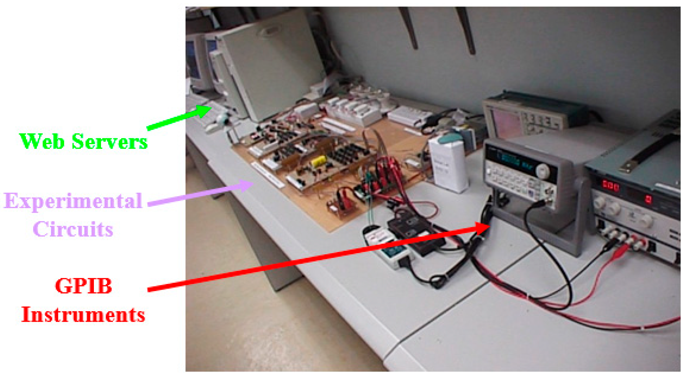
Figure 1 below shows the setup of the experimental rig installed the laboratory.
This paper is divided into 6 sections.
Section 1 and
Section 2 are the background and the introduction of the VPEL.
Section 3 describes the design and implementation of the VPEL systems with a detailed description of the user interface on the Web. An example of a typical session is shown.
Section 4 and
Section 5 present a description of developing the web-based teaching and the web-based simulations, respectively. An outline of educational benefits is presented in
Section 6, and finally,
Section 7 concludes the finding.
3. Design Procedures
Developments start from the function design, then the scope of operation, and finally the use of modular to realize the VPEL. The interface among the internet, laboratory measurement tool, and experimental rig are examined, and suitable methodology and protocols are made. The monitoring control of the experimental rig is through the general purpose interface bus (GPIB) and data acquisition (DAQ) from Labview [
31,
32]. Control and monitoring of the laboratory equipment includes the oscilloscope for the waveforms, signal generator for gate drive signals, and power supply for voltage input, all of which are implemented and therefore allow users to have access.
Two experiments were developed, namely the DC–DC converters experiment and the resonant zero-current-switching converter experiment [
29], the performances of which were evaluated.
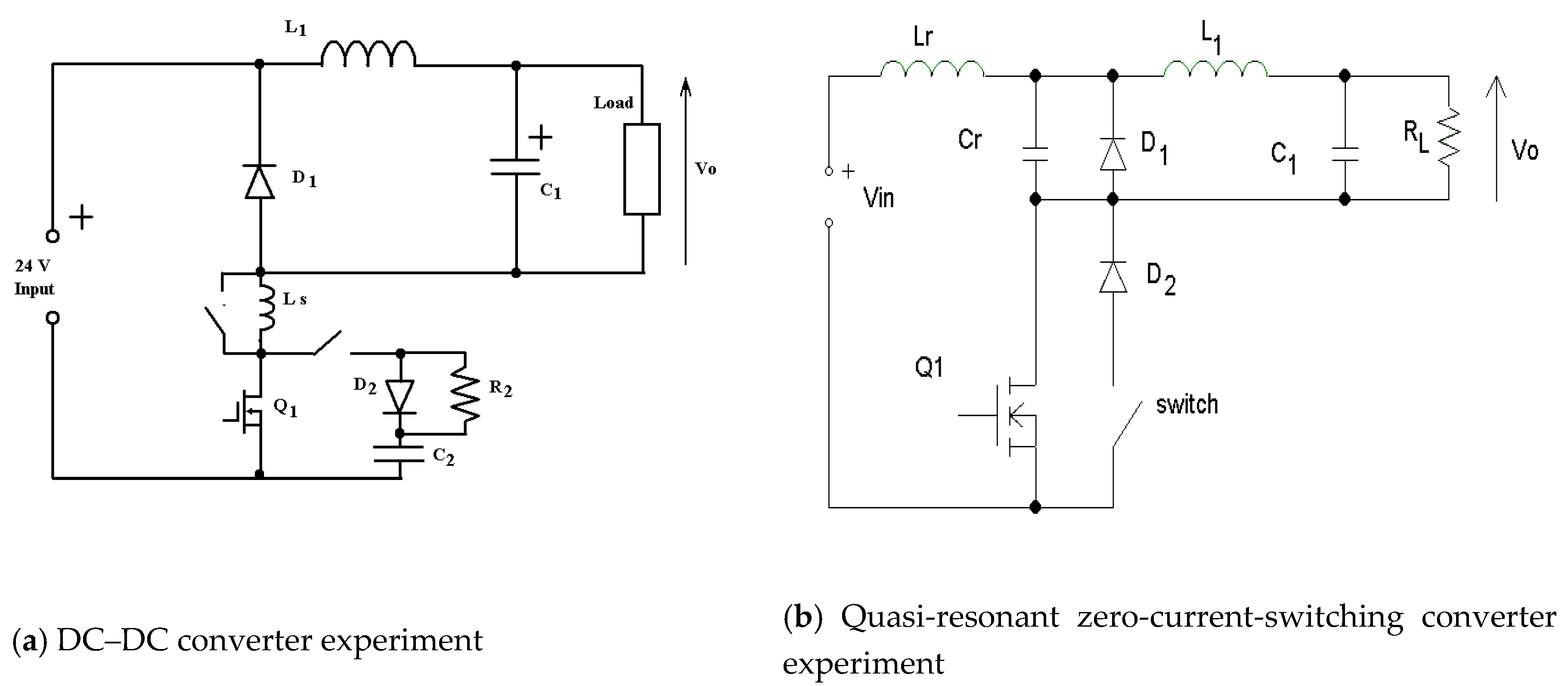
Figure 2 shows the circuits of the two experiments. The two experiments are fundamental power conversion tests for power electronics circuits. The first one is to examine the DC voltage to DC voltage power test. The output voltage V
o can be regulated by the transistor Q
1′s switching condition. The circuit also examines the parasitic inductance L
S and snubber formed by C
2, D
2, and R
2. Students can study the circuit operation with or without the parasitic unit. The waveforms of the inductor, and transistor switching condition are recorded by the VPEL and are delivered to users via the internet. Students can then examine the waveforms in order to study the effect of the duty ratio to the output V
o. The second one is to examine the resonant circuit for DC to DC power conversion. The study is to test the circuit operation under the resonance condition of inductor L
r and capacitor C
r. Inductor L
1 and capacitor C
1 are output filters. The switch’s function is to control the full wave or half wave resonance by allowing the resonant current to pass through the diode D
2, which produces a full-wave resonant, whilst the resonance is half wave when the switch is turned off. During the resonance, the transistor current is under a sinusoidal manner, and therefore, the inductor current is recorded to observe this phenomenon. Through these two experiments, students will understand the power conversion of two large circuits in the DC–DC power conversion learning.
The waveforms of the experiments are the most important for students to understand the operation. The LabView program’s oscilloscope display is slow and around 125 kbits/s, which is not fast enough to update the client side display, especially for high-frequency testing of the experiment, which runs at 50 kHz switching frequency. An alternative is to use real-time capture of the oscilloscope’s display, which will provide a more realistic feel of the oscilloscope’s display to achieve a real-time sensation.
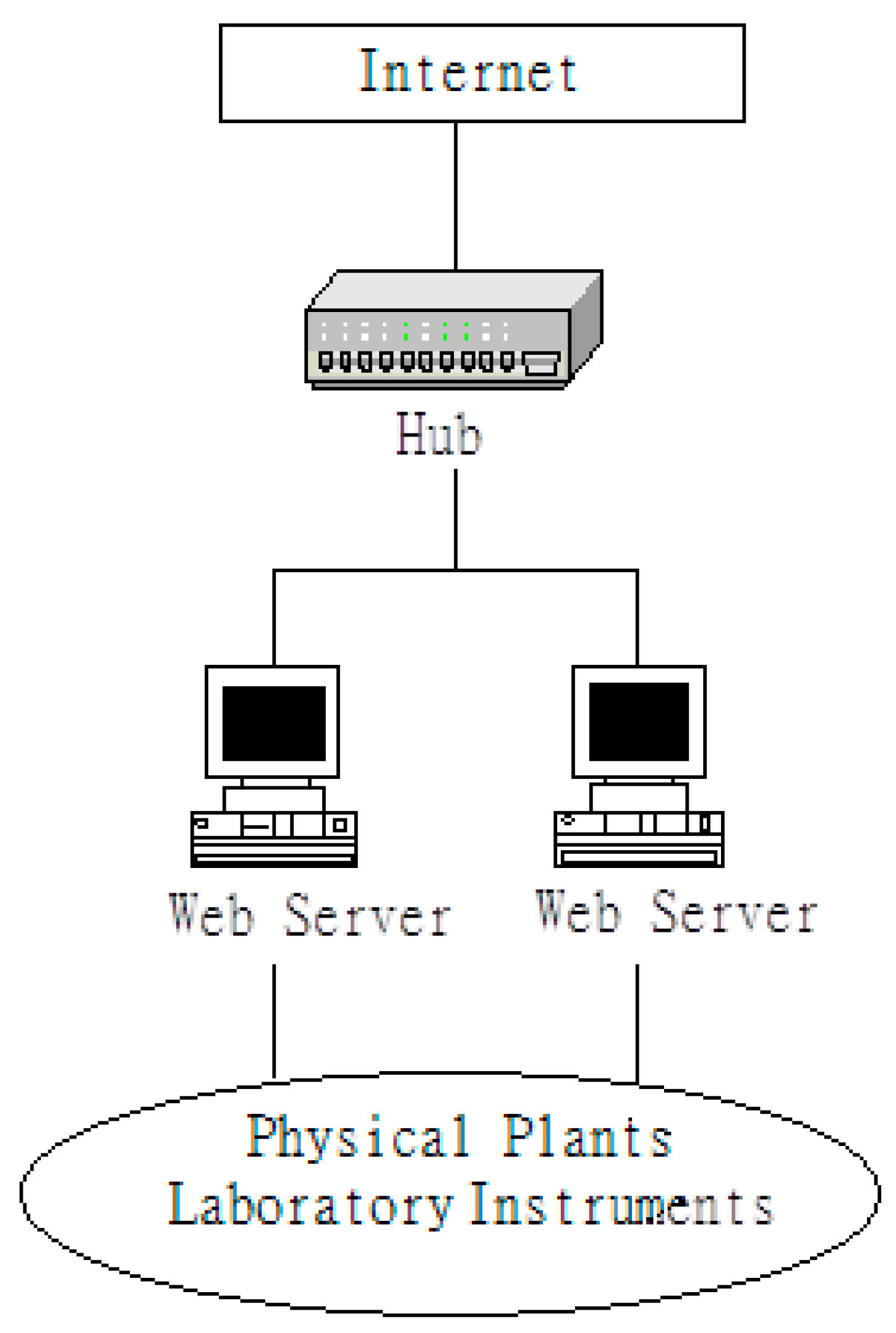
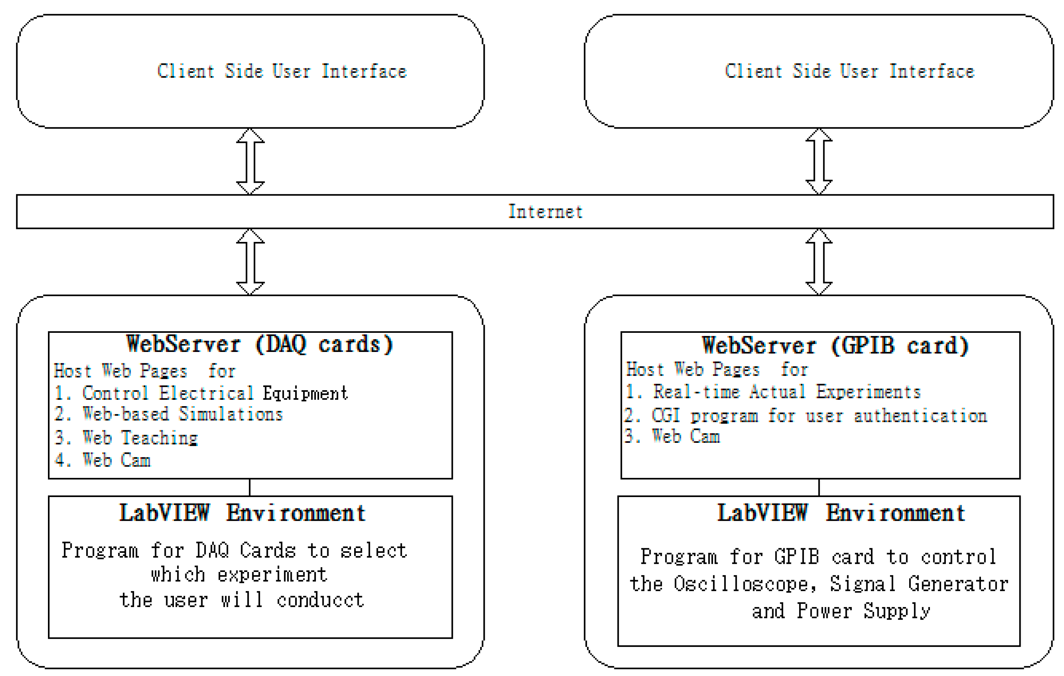
Figure 3 below gives a simple block representation of the hardware of the virtual lab connection to the internet.
4. The Virtual Remote Lab
4.1. System Architecture
Users make use of an internet browser as an interface to connect the virtual laboratory through the world wide web (WWW). The Java applets, Java Script, and Flash are used to make interfacing more interactive.
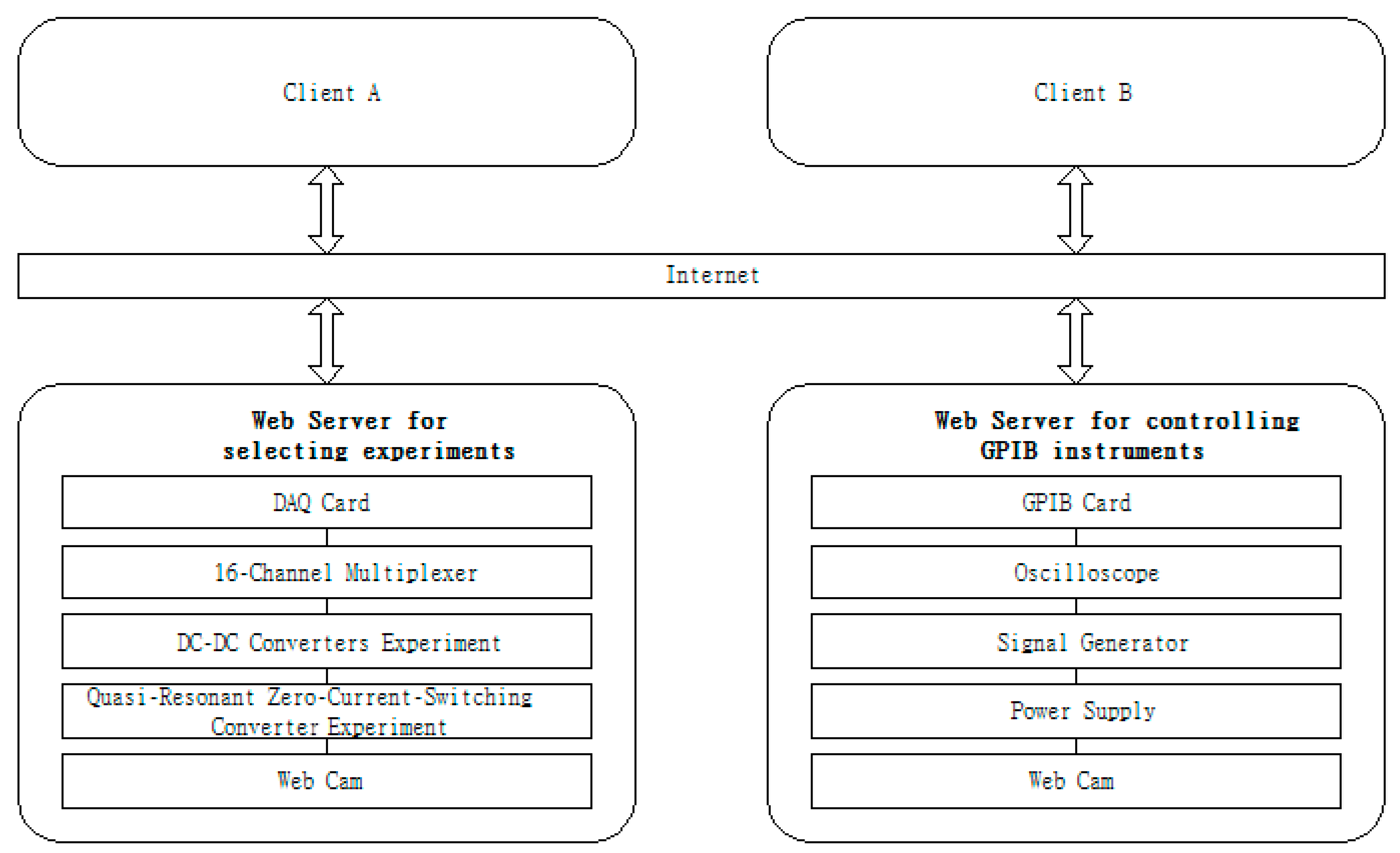
The key instruments, including oscilloscope, signal generator, and power supply, are placed in the laboratory without any supporting technician. All the equipment sets are normally off until any student logs on. This will save electrical energy, increase the life time of the rig, and reduce the risk of any circuit failure or fire risk. A Web cam is installed to broadcast the VPEL in the laboratory. The hardware structure of the communication, monitoring, and control of the VPEL is shown in
Figure 4.
Specifically, the various hardware subsystems are:
One PC with two data acquisition (DAQ) cards and an ethernet card serve as the experiment selector. It is connected to the internet through Wi-Fi. The experiment selector receives the DAQ cards control signal from the WWW server through a TCP/IP channel. Two DAQ cards are installed in a PC, which is connected to the Lan. A fixed TCP/IP is preferred rather than a dynamic IP to be used.
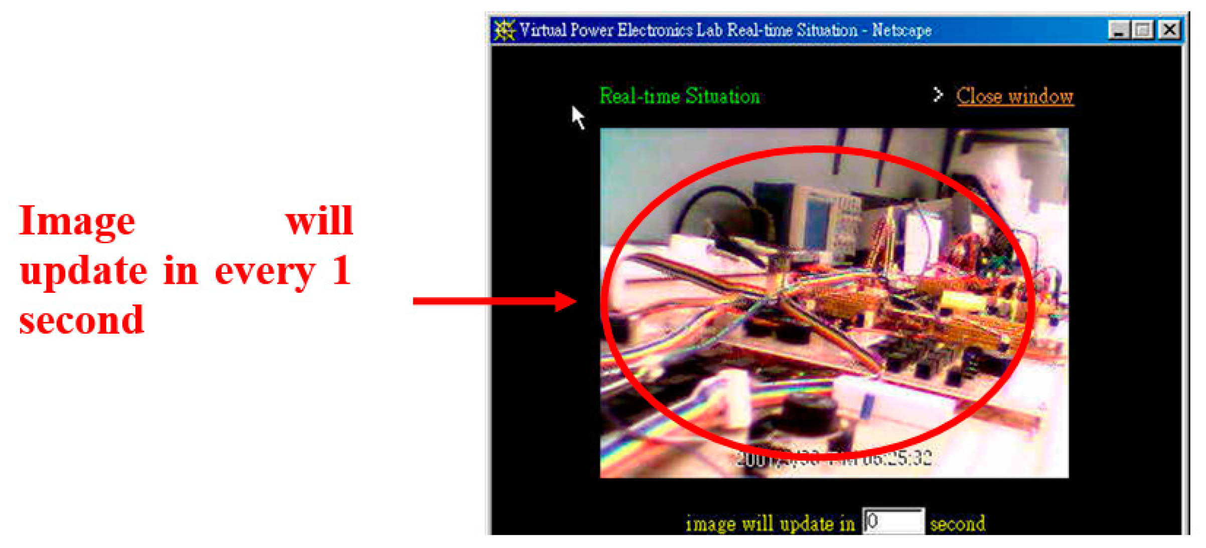
A web cam is installed as shown in
Figure 5, in which the laboratory condition is monitored. Students using the facility can see the remote control through their browser to activate the experimental rig wiring connection and the waveforms, voltage, and current wherever they are. Further, because the virtual lab will open 24/7 for all users to log on without any people physically in the Lab, intruders or fire alerts can be seen by users and are monitored by security services. Realtime capture is also made available.
A second computer is presented in the system as seen in
Figure 3. The GPIB card is installed to connect with the programmable instruments, including oscilloscope, signal generator and power supply, through the GBIP connection. The GPIB card can also be expanded to standard commands for programmable instruments (SCPI) compatible devices, and its command structures are defined in IEEE488.2 [
28].
The two computers are web servers to host the IP and virtual lab.
4.2. Software Structure
1. The Virtual Laboratory Tool
Figure 6 shows the software design of the VPEL that includes the serve side and client side. LabView activates the instrument control, and its internet-developer tool-kit facilitates the Web server. The cam pushes the live video to the client side through their IP upon the client’s request.
The clients are designed for IBM-compatible computers running Windows only, and the WWW browser is Chrome, Firefox, Netscape Navigator or equivalent.
The LabView program receives the parameters from the clients and controls the instrument in the laboratory. The interfacing in the client side is a graphic user interface that allows control of the remote-controlled instrument.
2. User Authentication in Virtual Lab
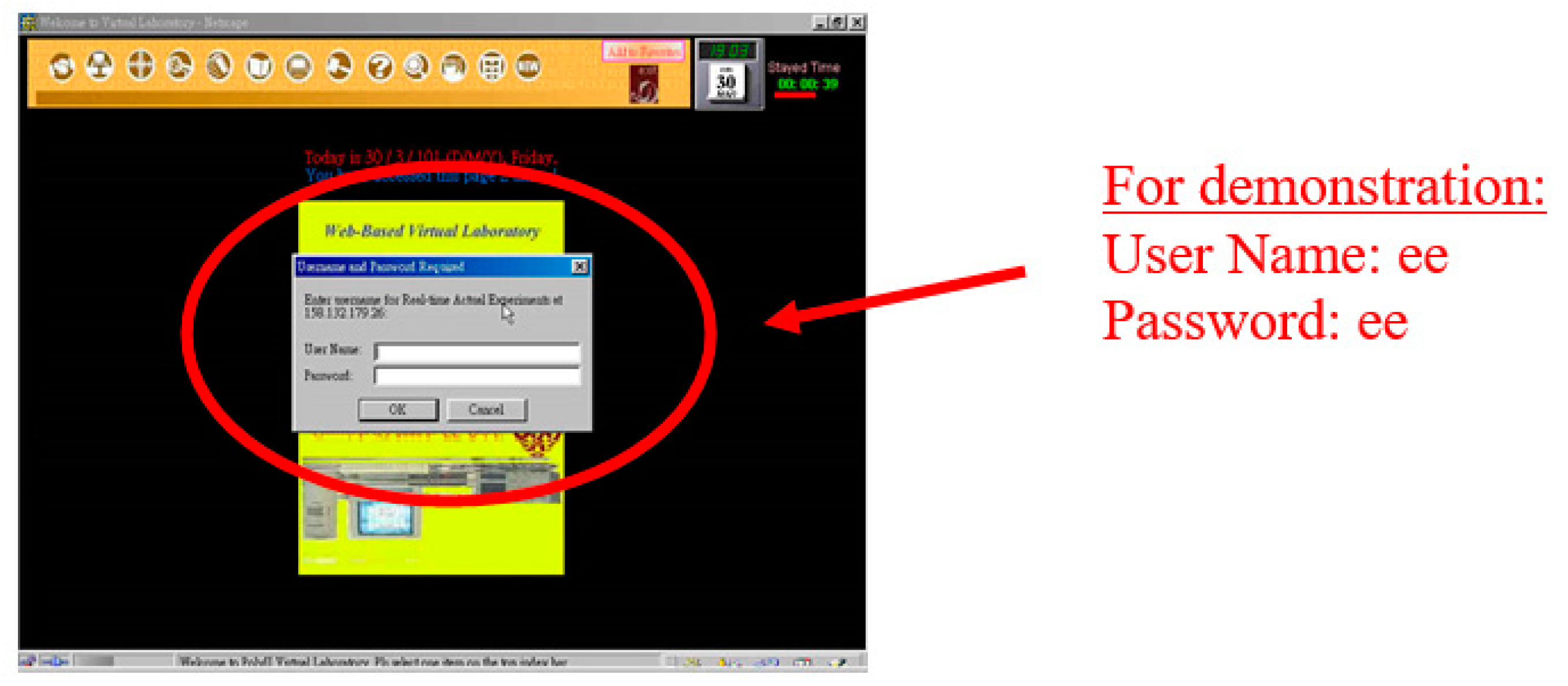
Authentication is to allow authorized users to access the VPEL. Making use of the LabView graphic program (LVGP), the access control can be done as shown in
Figure 7. It consists of the Login Block and the Password.vi. A user inputs the login account name and the password that is then broken into field name-value pairs to Password.vi for verification before access rights are sent.
3. Remote Instruments Control through Internet
Common gateway interface (CGI), coded in LabView graphical language G, was selected to communicate between the client’s computer and the Web server. It sets up interaction to the external application. HTML is used for CGI programming. Data transfer between the client’s computer and the web server is simple through HTML ‘form’ and ‘input’ tags. LabView was implemented with virtual Instrument (VI) and communicates using TCP. TCP Listen.vi waits for an incoming request and is read by the TCP read.vi. The string data are written to write.vp and release the TCP connection by Close Connection.vi.
Figure 8 shows the developed remote instrument control.
A specific web page for the function of user interface is provided to enable user adjustment of experiment parameters, which are accepted by the server. The web server then activates the CGI program and transmits instrument’s parameters to it.
The CGI program then establishes a TCP connection with listener.vi by the G language on the computer and passes the parameters to listener.vi. The listener.vi on the PC turns on the local instrument control VI and passes the command string and parameter to the attached instrument. After that, the TCP connection will be released, and the CGI program returns information to remote side. The instrument control can be remotely made through the interfacing software.
4.3. The User Interface
A user-friendly and realistic interfacing is important for the system, especially as a teaching and learning tool. A beautiful graphic is needed.
The graphic interface display of the VPEL on the client side is implemented using Flash [
9] and HTML [
10].
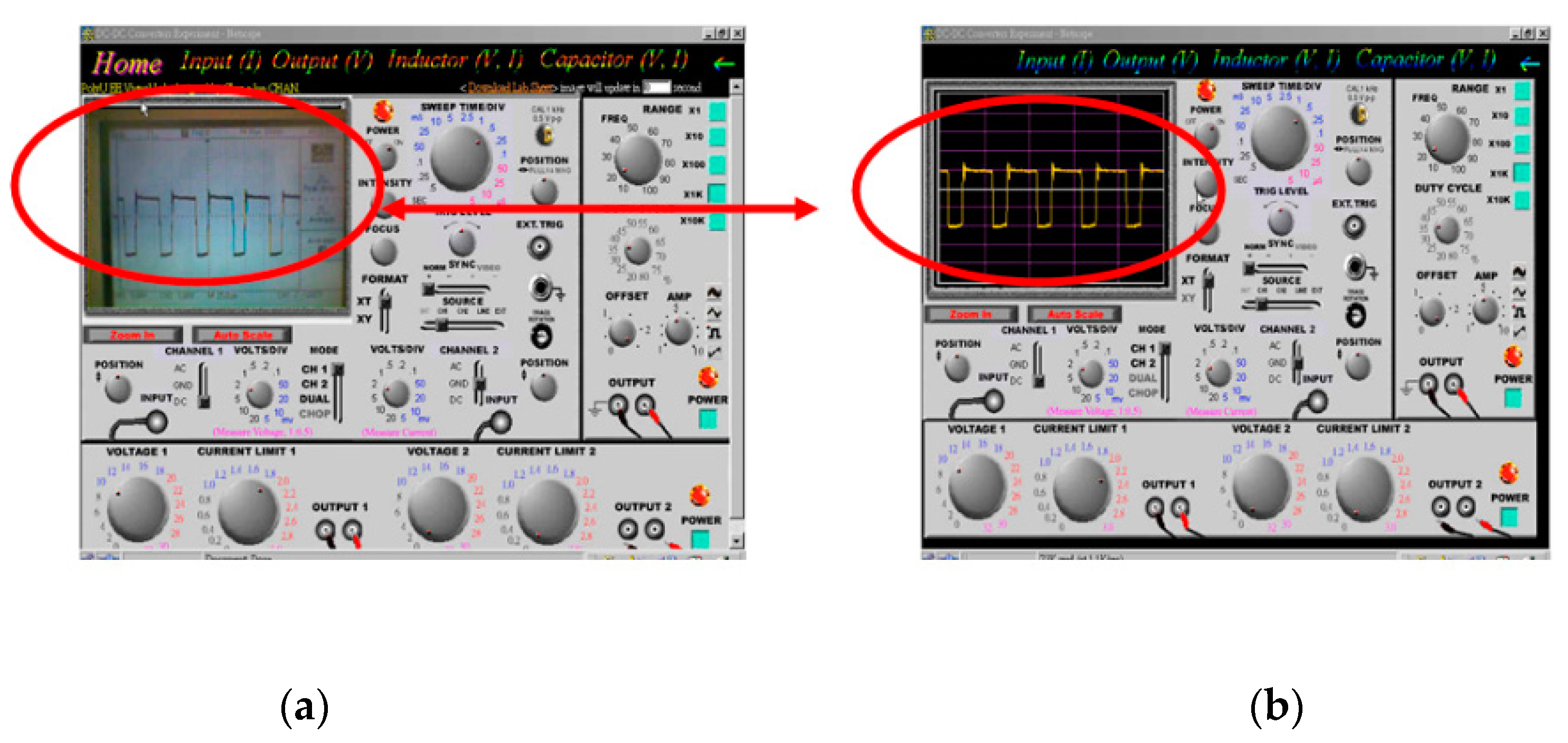
Figure 9a,b shows the display panels of the oscilloscope, signal generator, and power supply, which are the key measurement tools in the experiment.
The salient points of the user interface are:
The display panels of the oscilloscope, signal generator, and power supply are made in a graphical manner.
The system was implemented with two user interfaces to the key measurement devices Oscilloscope. In addition to the LabVIEW program in “picture” form, another is the capture of the actual Oscilloscope’s display by a camera. Because the internet communication speed supported by LabVIEW is around 125 kbit/s, it is very slow for updating the oscilloscope’s display in the client side in a “real time” sensation. Hence, the latter method is better to implement to update the oscilloscope’s display in the client side to achieve a more “real-time” sensation and a more realistic feel of the oscilloscope’s display.
The control of the oscilloscope, including the amplitude and time base scale, is done by turning of control buttons, and knobs through mouse control in users’ web page give a more virtual reality feel of operating the instrument. The student simply moves the mouse to the FREQ knob and to turn the knob for frequency control.
All the associated laboratory sheets with the procedure are available together with the VPEL. Students can see the procedure and simultaneously conduct the experiment. The experiment can therefore be conducted with no difference from conducting it physically in the laboratory.
5. Typical Virtual Lab Session
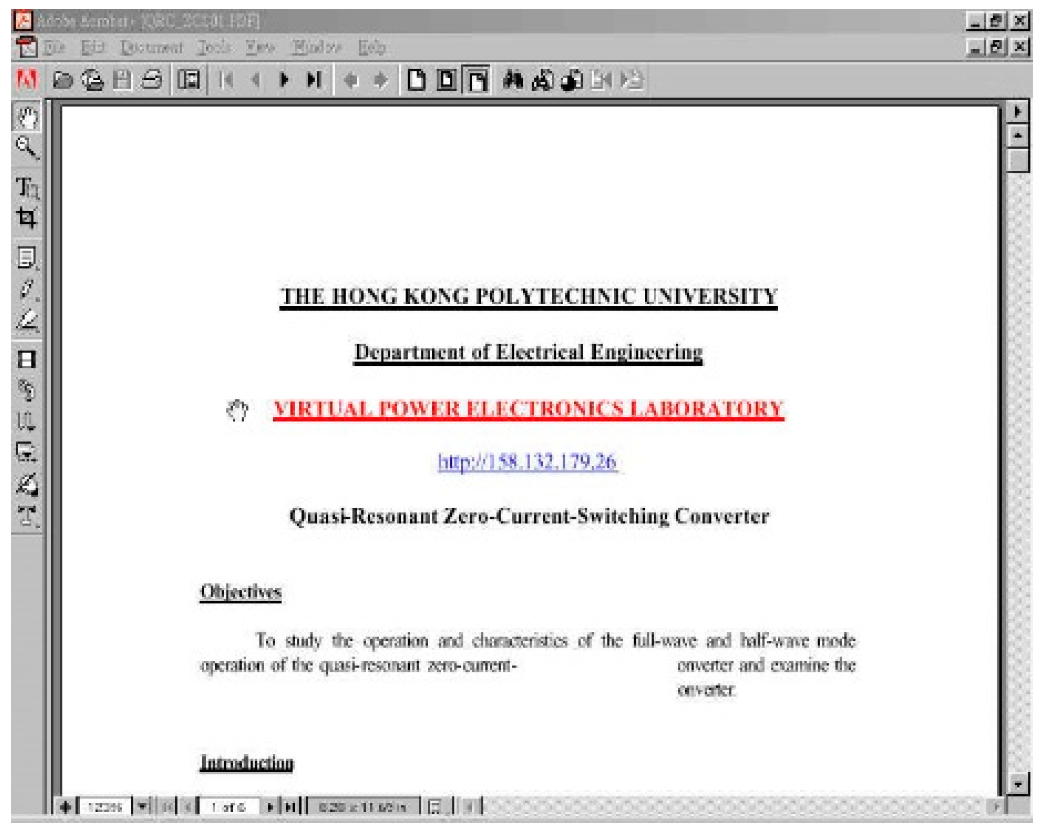
Two laboratory sessions were programmed and developed in the VPEL. They are power electronics experiment namely: “DC–DC converters” and “quasi-resonant zero-current-switching converter”. The experiments were to examine the power converters under DC operations and pulse switching conditions.
The proposed VPEL was programmed to be operated as follows:
6. Educational Benefits
6.1. Benefit to Subject Students
Our virtual lab is based on the idea that learning can be nonlinear in nature. The VPEL complements the conventional laboratory classes by allowing students to conduct the session at a convenient date and time. The VPEL does not involve any running cost. Therefore, the lab can be made available to the public. This is particularly useful to promote power electronics teaching and learning. It also helps students worldwide to try hardware laboratories in a controlled and safe manner. It even provides an alternative manner for foreign students to understand power electronics teaching at university.
6.2. Student Trial
The VPEL was provided to students. The trial class found that students liked the setup very well. It is a real and remotely controlled experiment in power electronics course that allows various hardware experiments to be conducted remotely and accelerates the students’ learning. The setup is capable of being extended to other power electronics or electrical engineering experiment easily using the same method.
A comprehensive survey of the virtual lab in terms of performance and quality was conducted. Eighty-five questionnaires were sent to users to express their comments of VPEL. The response percentage was 62. Overall, the feedback from them was positive. According to their feedback, VPEL is an alternative method of laboratory teaching. It is different from other types of virtual reality as it is real hardware. The VPEL is real, and the experimental work is highly realistic. Even the images and the connection are real, and it is just presented in a remotely-controlled manner. Therefore, the students like this type of virtual laboratory with remote control capability of actual hardware. This is a feeling that cannot be compared to conventional virtual reality. The VPEL:
Increases their learning interest;
Enhances the understanding of power electronics;
Conducts the hardware in a real setup rather than simulation;
Is of high virtual laboratory standard.
7. Conclusions
Multimedia is now a trend for web-based teaching and learning. The engineering subject requires significant hardware learning, and therefore, virtual laboratories are an alternative to allow higher utilization of the hardware, and users can conduct the session in a prearranged booking. Safety is enhanced, and all steps of the experiments are preprogrammed, and therefore, the instructions are extremely clear and easy to follow. This method is completely different as compared to the conventional case, in which the support was highly dependent on laboratory assistance.
The remotely controlled hardware for power electronics is one of the first sets of advanced learning in power electronics circuit systems in the world. It provides the setting, wiring connection, load variation, and waveforms adjustment to facilitate the learning of the power converter.
Author Contributions
Conceptualization, K.W.E.C.; methodology, K.W.E.C. and C.L.C.; investigation, K.W.E.C. and C.L.C.; writing—review and editing, K.W.E.C. and C.L.C.; supervision, K.W.E.C.
Funding
This research was funded by UGC teaching Development Grant Hong Kong and Hong Kong Polytechnic University 845G Project.
Acknowledgments
The authors gratefully acknowledge the Teaching Development Grant of the University Grants Committee, Hong Kong for the financial support of the project.
Conflicts of Interest
The authors declare no conflict of interest.
References
- Orduña, P.; Zutin, D.G.; Govaerts, S.; Zorrozua, I.L.; Bailey, P.H.; Sancristobal, E.; Salzmann, C.; Rodriguez-Gil, L.; DeLong, K.; Gillet, D.; et al. An Extensible Architecture for the Integration of Remote and Virtual Laboratories in Public Learning Tools. IEEE Rev. Iberoam. Tecnol. Aprendiz. 2015, 10, 223–233. [Google Scholar] [CrossRef]
- de Magistris, M. A MATLAB-based virtual laboratory for teaching introductory quasi-stationary electromagnetics. IEEE Trans. Educ. 2005, 48, 81–88. [Google Scholar] [CrossRef]
- Casals-Torrens, P. Virtual Laboratory for Learning Asynchronous Motors in Engineering Degrees. IEEE Rev. Iberoam. Tecnol. Aprendiz. 2013, 8, 71–76. [Google Scholar] [CrossRef]
- Rosenberg, J.M.; Lawson, M.A. An Investgation of Students’ Use of a Computational Science Simulation in an Online High School Physics Class. Educ. Sci. 2019, 9, 49. [Google Scholar] [CrossRef]
- Goodwin, G.C.; Medioli, A.M.; Sher, W.; Vlacic, L.B.; Welsh, J.S. Emulation-Based Virtual Laboratories: A Low-Cost Alternative to Physical Experiments in Control Engineering Education. IEEE Trans. Educ. 2011, 54, 48–55. [Google Scholar] [CrossRef]
- Callaghan, M.J.; McCusker, K.; Losada, J.L.; Harkin, J.; Wilson, S. Using Game-Based Learning in Virtual Worlds to Teach Electronic and Electrical Engineering. IEEE Trans. Ind. Inform. 2013, 9, 575–584. [Google Scholar] [CrossRef]
- Atanasijević-Kunc, M.; Logar, V.; Karba, R.; Papic, M.; Kos, A. Remote Multivariable Control Design Using a Competition Game. IEEE Trans. Educ. 2011, 54, 97–103. [Google Scholar] [CrossRef]
- Hoefer, W.; So, P. A time-domain virtual electromagnetics laboratory for microwave engineering education. IEEE Trans. Microw. Theory Tech. 2003, 51, 1318–1325. [Google Scholar] [CrossRef]
- Martínez-Román, J.; Perez-Cruz, J.; Pineda-Sanchez, M.; Puche-Panadero, R.; Roger-Folch, J.; Riera-Guasp, M.; Sapena-Bano, A. Electrical Machines Laminations Magnetic Properties: A Virtual Instrument Laboratory. IEEE Trans. Educ. 2015, 58, 159–166. [Google Scholar] [CrossRef]
- Ruiz, E.S.; Martin, A.P.; Orduña, P.; Martin, S.; Gil, R.; Larrocha, E.R.; Albert, M.J.; Diaz, G.; Meier, R.; Castro, M. Virtual and Remote Industrial Laboratory: Integration in Learning Management Systems. IEEE Ind. Electron. Mag. 2014, 8, 45–58. [Google Scholar] [CrossRef]
- Ullah, A.M.; Harib, K. Tutorials for Integrating CAD/CAM in Engineering Curricula. Educ. Sci. 2018, 8, 151. [Google Scholar] [CrossRef]
- Butz, B.P.; Duarte, M.; Miller, S.M. An intelligent tutoring system for circuit analysis. IEEE Trans. Educ. 2006, 49, 216–223. [Google Scholar] [CrossRef]
- Murphey, T.D. Teaching Rigid Body Mechanics Using Student-Created Virtual Environments. IEEE Trans. Educ. 2008, 51, 45–52. [Google Scholar] [CrossRef]
- Foist, R.B.; Grecu, C.S.; Ivanov, A.; Turner, R.F.B. An FPGA Design Project: Creating a PowerPC Subsystem Plus User Logic. IEEE Trans. Educ. 2008, 51, 312–318. [Google Scholar] [CrossRef]
- Palop, J.; Teruel, J. Virtual work bench for electronic instrumentation teaching. IEEE Trans. Educ. 2000, 43, 15–18. [Google Scholar] [CrossRef]
- Akcayol, M.; Cetin, A.; Elmas, C. An educational tool for fuzzy logic-controlled BDCM. IEEE Trans. Educ. 2002, 45, 33–42. [Google Scholar] [CrossRef]
- Nakamoto, P.T.; Cardoso, A.; Lamounier, E.; Mendes, E.B.; Takahaschi, E.; Carrijo, G.A. An Virtual Environment Learning of Low Cost for the Instruction of Electric Circuits. IEEE Lat. Am. Trans. 2010, 8, 695–702. [Google Scholar] [CrossRef]
- Kikuchi, T.; Fukuda, S.; Fukuzaki, A.; Nagaoka, K.; Tanaka, K.; Kenjo, T.; Harris, D. DVTS-based remote laboratory across the Pacific over the gigabit network. IEEE Trans. Educ. 2004, 47, 26–32. [Google Scholar] [CrossRef]
- Bose, R. Virtual Labs Project: A Paradigm Shift in Internet-Based Remote Experimentation. IEEE Access 2013, 1, 718–725. [Google Scholar] [CrossRef]
- August, S.E.; Hammers, M.L.; Murphy, D.B.; Neyer, A.; Gueye, P.; Thames, R.Q. Virtual Engineering Sciences Learning Lab: Giving STEM Education a Second Life. IEEE Trans. Learn. Technol. 2016, 9, 18–30. [Google Scholar] [CrossRef]
- Refsland, S.; Ojika, T.; Addison, A.; Stone, R. Virtual Heritage: Breathing new life into our ancient past. IEEE Multimed. 2000, 7, 20–21. [Google Scholar] [CrossRef]
- González, I.; Calderón, A.J. Development of Final Projects in Engineering Degrees around an Industry 4.0-Oriented Flexible Manufacturing System: Preliminary Outcomes and Some Initial Considerations. Educ. Sci. 2018, 8, 214. [Google Scholar]
- Dutta, S.; Prakash, S.; Estrada, D.; Pop, E. A Web Service and Interface for Remote Electronic Device Characterization. IEEE Trans. Educ. 2011, 54, 646–651. [Google Scholar] [CrossRef]
- Chang, G.W.; Yeh, Z.M.; Chang, H.M.; Pan, S.Y. Teaching photonics laboratory using remote-control web technologies. IEEE Trans. Educ. 2005, 48, 642–651. [Google Scholar] [CrossRef]
- Onime, C.; Uhomoibhi, J.; Pietrosemoli, E. A demonstration of an augmented virtuality based solar energy power calculator in electrical engineering. In Proceedings of the 11th International Conference on Remote Engineering and Virtual Instrumentation (REV), Porto, Portugal, 26–28 February 2014; pp. 198–199. [Google Scholar]
- Lomonova, E.A.; Paulides, J.; Wilkins, S.; Tegenbosch, J. ADEPT: “Advanced electric powertrain technology”—Virtual and hardware platforms. In Proceedings of the 10th International Conference on Ecological Vehicles and Renewable Energies (EVER), Monte Carlo, Monaco, 31 March–2 April 2015. [Google Scholar]
- Russell, S.; Creighton, O. Virtual world tools for Requirements Engineering. In Proceedings of the 4th International Workshop on Multimedia and Enjoyable Requirements Engineering (MERE’11), Trento, Italy, 30 August 2011; pp. 17–20. [Google Scholar]
- Cheng, K.W.E. Classical Switched-Mode and Resonant Power Converters; The Hong Kong Polytechnic University: Hong Kong, China, 2002; ISBN 962-367-364-7. [Google Scholar]
- Cheng, K.W.E.; Evans, P.D. Parallel-mode extended-period quasi-resonant converter. IEE Proc. B 1991, 138, 243–251. [Google Scholar]
- LabVIEW (Laboratory Virtual Instrument Engineering Workbench). User Manual; National Instruments: 2011. Available online: http://www.ni.com/pdf/manuals/374629c.pdf (accessed on 29 April 2019).
- LabVIEW online help. National Instruments. Available online: http://www.ni.com/getting-started/labview-basics/online-help (accessed on 29 April 2019).
- Caristi, A.J. IEEE-488 General Purpose Instrumentation Bus Manual; Academic Press: San Diego, CA, USA, 1989. [Google Scholar]
© 2019 by the authors. Licensee MDPI, Basel, Switzerland. This article is an open access article distributed under the terms and conditions of the Creative Commons Attribution (CC BY) license (http://creativecommons.org/licenses/by/4.0/).
