Article

Comparing Performance of 3D-Printed and Injection-Molded Fiber-Reinforced Composite Parts in Ring-Spinning Traveler Application

by
S. M. Fijul Kabir
1,2,*,
Kavita Mathur
1 and
Abdel-Fattah M. Seyam
1
1
Wilson College of Textiles, North Carolina State University, Raleigh, NC 27965, USA
2
Department of Industrial and Production Engineering, National Institute of Textile Engineering and Research, Dhaka 1350, Bangladesh
*
Author to whom correspondence should be addressed.
Technologies 2021, 9(4), 75; https://doi.org/10.3390/technologies9040075
Submission received: 21 August 2021 / Revised: 8 October 2021 / Accepted: 9 October 2021 / Published: 12 October 2021

Abstract

:
Fiber-reinforced 3D printing (3DP) technology is a recent addition to the material extrusion-based 3DP process unlocking huge potential to apply this technology for high-performance material fabrication with complex geometries. However, in order to take the full advantage of this technology, a comparative analysis with existing technologies targeting a particular application is necessary to understand its commercial applicability. Here, an applied composite part, ring-spinning travelers, has been developed using the unique design features of fiber-reinforced 3DP technology that is beyond the capability of the currently used technology; the injection molding, quality, and performance of the printed and molded travelers were investigated and compared. The results demonstrated that fiber-reinforced 3DP is a promising technology that offers a lot of flexibility regarding reinforcement patterns and materials including both short and continuous fibers to tailor the performance, although the printed travelers showed poorer surface characteristics and wear resistance than the molded travelers. Based on the present analysis, a number of recommendations have been proposed on the design of the traveler to apply the technology effectively and use the printer to improvise and manipulate the performance of the travelers.

1. Introduction

Additive manufacturing, also called 3D printing, is at the vertex of widely accepted advanced manufacturing technologies because of its unique ability to develop intricate geometric structures with numerous design flexibilities in a single setup, involving minimum process steps and waste generation [1,2]. The recent advent of reinforcing 3D-printed structures with fillers (short and long fibers) has brought a phenomenal improvement in the performance of the printed part and put the technology far forward with regard to high-performance applications [3,4].
While 3D-printed plastic parts are extensively used commercially for the prototyping and fabrication of different devices such as sensors, electric circuits, batteries, capacitors, and micro-channels [5,6,7], current research on 3D-printed fiber-reinforced plastic parts includes the fabrication of test samples according to the dimensions (often a rectangular bar) of test standards and outlining the potential applications based on the investigated attributes [2,8]. However, due to the absence of a comparative study of quality and performance of composites parts developed by 3D printing and currently used technology, the commercial application of 3DP to develop fiber-reinforced composite parts is barely found. On the other hand, this study is very important to guide potential commercial users regarding whether to adopt this technology as well as the printer manufacturers to consider the further customization of printers from a user perspective to widen its mass applicability.
Most of the high-performance applications of 3D-printed composite functional parts include automobile and aircraft body parts [9,10,11,12,13]. Tasch et al. [11] developed a motorcycle fuel tank using different types of 3DP technologies (laser sintering, multijet fusion, and hot lithography) and investigated the impact behavior with fractographical analysis. However, these technologies could not incorporate reinforcing material in the structure, which resulted in low mechanical performance. Fused deposition modeling (FDM) is a favorable technology that involves both fiber and polymer to fabricate composites [2,14]. FDM-printed composite parts have been developed for aircraft applications including propellers for aerial vehicles, side panel elements, and sub-structures for morphing aircraft, among which a propeller was fabricated using thermoplastic polymers (polylactic acid) without reinforcement, leading to poor impact strength [13]. The side panel elements for rocket and space structures have been developed by Azarov et al. [9], where the researchers used continuous carbon fiber pre-impregnated in thermoset polymer as the fiber component and thermoplastic polymer as the matrix component. They proposed an algorithm combining proportional topology optimization and fiber steering technique to design a lightweight side panel element. Rajs et al. [10] fabricated 3D-printed sub-structures with chopped carbon-reinforced polyamide (Nylon 6) and examined their mechanical properties (flexural) along with validation through finite element modeling. These studies did not include side-by-side comparisons between the composite parts developed using 3DP and currently used technology from different viewpoints such as design flexibility, the quality and performance of resulting parts, as well as time and cost analysis. On the other hand, these analyses are essential to understand the feasibility of fiber-reinforced 3DP technology and discover its limitations for prospective improvement. Industrial application of 3DP for the bulk production of fiber-reinforced composites involves high cost, as it requires a long fabrication time. As a result, comparing the cost at this time becomes unfair and out of the scope of the research. Moreover, the cost structure of our industry is often kept confidential. Therefore, the main focus of this paper is to study properties comparison; however, future research should address cost comparison involving the scalability of 3D printers.
In the present research, an applied composite part, namely, the ring-spinning traveler used in the yarn manufacturing process from short staple fibers has been fabricated using fiber-reinforced 3DP technology. The ring-spinning traveler, a tiny dynamic part in ring spinning, spins around the ring at very high speed (up to 38 m/s with respective spindle speed (or traveler speed) of 18,000 rpm) principally to impart twist and wind the yarn onto bobbin. This high speed generates tremendous frictional force between the ring and travelers that causes high wear on the traveler, requiring frequent replacement [15]. Therefore, this part needs to be smooth, highly abrasion resistant, strong, and lightweight so that it becomes long lasting and generates minimum heat from high frictional forces with subsequent fast heat dissipation [16,17]. Nylon and nylon-based composite travelers characterized with high abrasion resistance are some of the ideal materials commercially used for manufacturing travelers to process both natural (short staple fibers, such as cotton and their blends) and synthetic (continuous filament fibers, such as polyester, nylon, and acrylic) yarns. Traditional fiber-reinforced composite manufacturing technologies include compression molding, vacuum bag molding, pultrusion, and injection molding. Traditional technologies including injection molding necessitate a separate mold for every structural variation of the part involving process complexity in preparing the preforms [18,19,20]. In addition, the common practice to reinforce fiber in injection molding requires a polymer matrix to be compounded with short fibers first and then injection molded to achieve a specific shape. 3DP is a simple one-step process requiring no mold and offering a myriad customization of reinforcement patterns and materials including both short and continuous fibers to tailor the performance. However, for developing ring-spinning travelers, injection molding is one of the most commonly used technologies practiced by the industries. The present research aims to assess potential the commercial viability of the 3DP with respect to industrially practiced injection-molding technology. This has been demonstrated by using a nylon traveler as an example case of high-performance application of a functional composite part.

2. Materials and Methods

2.1. Research Design

Two types of travelers with different designs (Table 1) have been selected for this research that were fabricated using current technology (injection molding) from AB Carter Inc. (Gastonia, NC, USA), the industry partner of the research and fiber-reinforced 3DP technology from Mark Two printer (Markforged Inc., Boston, MA, USA, which is the only commercial fiber-reinforced 3D printer manufacturer at the time of developing the current research). The travelers were designed by AB Carter and fabricated with different materials within the scope of the printer. Details of the scopes and capabilities of the printer are reported in [3]. Commercially, AB Carter use a Nylon 6:6 plastic mold to manufacture unreinforced travelers and a chopped fiberglass-reinforced Nylon 6:6 mold for reinforced travelers. Between the traveler types, G-77-C was developed with plastic and fiber-reinforced plastic following both technologies (injection molding and 3DP). However, based on the scopes of the 3D printer, the compatible plastic filaments are Nylon 6 and the chopped carbon fiber-reinforced Nylon 6. Additionally, the used 3DP technology allows to incorporate continuous fiber (bundled with hundreds of filaments, pre-impregnated by Nylon 6) in the plastic or short-fiber containing plastic material with huge flexibilities in terms of customized fiber orientation and placement, which is very tedious and often beyond capability of traditional technology. Hence, it is justifiable to investigate the effect of continuous fiber with unique fiber orientation on the performance of travelers. Nonetheless, to place continuous fiber, the printing part needs to have a substantial dimension, which was beyond the size of G-77-C. Therefore, relatively a larger traveler, J-102-C, was selected to apply continuous fiberglass, which was compared with that of short-fiber-reinforced molded traveler. The compositions of the materials and their properties are summarized in Table 2.

2.2. Fabrication of Ring-Spinning Travelers by 3DP

The technology of a Markforged composite printer (Mark Two) has two printing nozzles for plastic filaments (either Nylon 6 or short carbon fiber containing Nylon 6, commercially know as Onyx) and continuous fiber filament (such as carbon fiber, fiberglass, Kevlar, high-strength high-temperature fiberglass). The CAD designs of the travelers in STL (standard tessellation language) file format is obtained from the industry, which were then transferred to Eiger (the designated slicer for the printer, Markforged Inc., Boston, MA, USA) to set the printing parameters, as mention in Table 3. A note is worth mentioning about the orientation of the continuous fiber during slicing and setting print parameters. The purpose of using continuous fiber was to improve the abrasion resistance, and it could be achieved when the continuous fiber (which is composite with fiber and matrix as explained in [3]) might come into direct contact with the ring during functioning. In this regard, the best consideration would be to put the continuous fiber as a wall layer; however, the Eiger slicer does not allow doing so, and it is limited to using plastic for the bottom (floor), top (roof), and wall layers. Therefore, the number of wall layers was minimized to one (although two layers are recommended for good part quality), and concentric orientation with one concentric ring (to maintain optimize target weight) was chosen to proximate the potential contact with the ring.

2.3. Quality and Performance Evaluation

The quality and performance were assessed following industrial practice that the industries apply for the assessment of travelers including surface finish and wear due to friction and abrasion between the ring and traveler. Additionally, the dimensional accuracy and variation in the weight of the printed travelers were assessed to deem the print precision. The trial setup to evaluate wear resistance included a spinning frame (Meera Heavy Duty Ring Twister (R-250) 4 Spindle, Meera Industrial Limited: Surat, Gujrat, India) running with 100% polyester yarn at 4000 rpm, twists per meter of 400 turns, and a ring diameter and height of 165 mm and 17 mm, respectively.

3. Results and Discussion

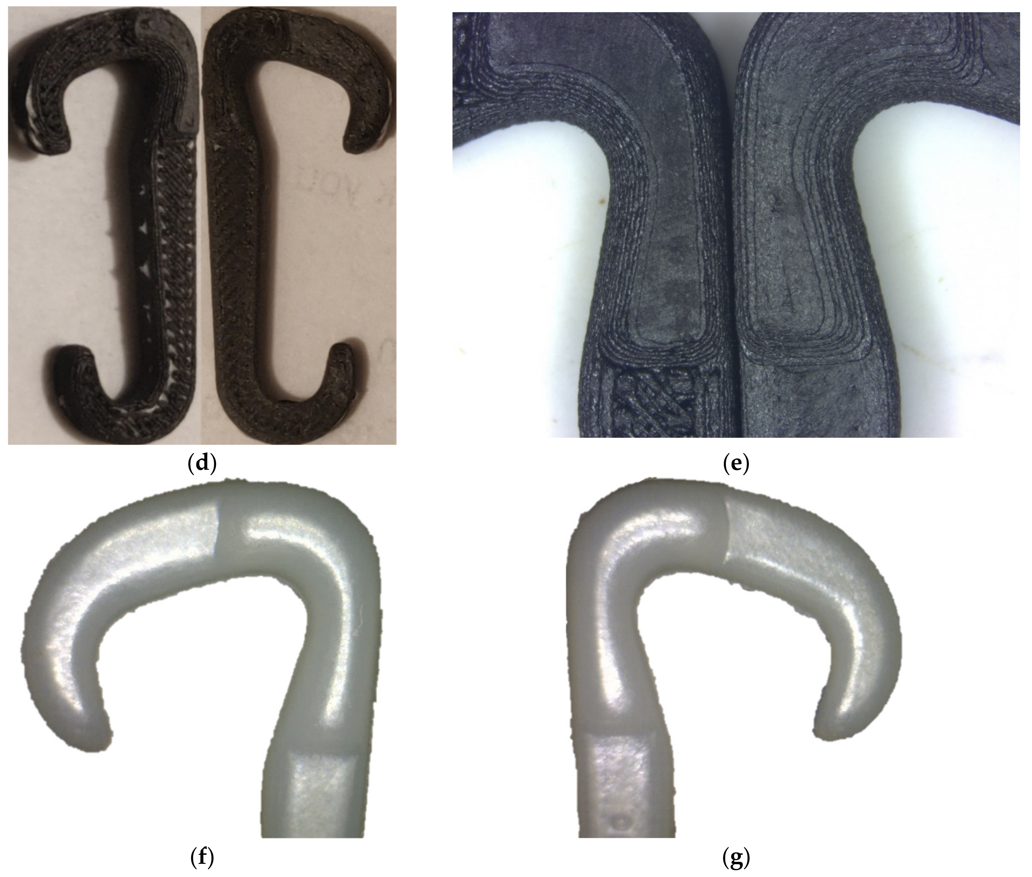
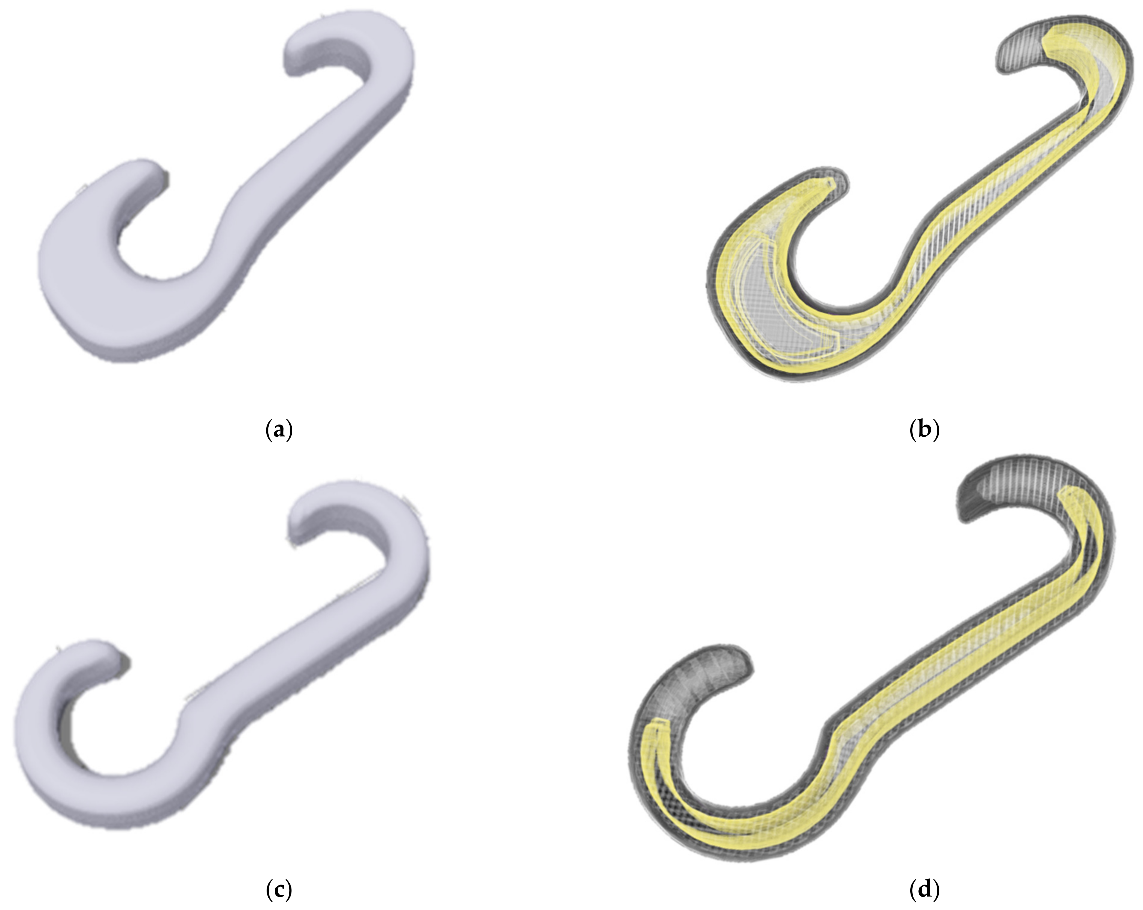
3.1. Print Precision

Print precision includes accuracy in the dimension and weight of the printed parts. There are three types of dimensions and weights to be considered here, such as target, estimated, and measured; while target is the actual value to be achieved based on the model of the traveler (as in molded parts), estimated is the value given by 3D printing software, and finally measured is the value taken from the printed parts. The target values for dimensions are mentioned in Table 1 and Table 4. Generally, when the CAD model is loaded to the slicer, it transfers the dimensions to closer multiplications of the raster width (raster density) and layer height [3]. Here, there is almost no change in dimension in the X-Y direction (hence, there is negligible variation in the length and width direction), which is controlled by the movement of the print head with the extruding nozzles. As the length and width coverage are defined by the raster (print bead) density, the ignorable change in the printed length and width might be due to the variation between the given area and the area covered by the integer number of rasters. However, the relative discrepancy in thickness (Z direction) was observed to be higher, controlled by the layer height, which is eventually governed by the movement of the build plate along with printed parts. The build plate is subjected to leveling by the screw in addition to its inherent degree of flatness [3]. Consequently, among the dimensions, the thickness varied the most, which has also been reported by other researchers [21], but overall, the dimension of the printed and molded parts are almost same.
Controlling the weight of the traveler for a given dimension is a significant consideration having huge impact on the performance of the traveler itself (such as abrasion, generated heat, and rate of heat dissipation) as well as the quality of the manufactured yarn (such as twist and hairiness of yarn) [22,23,24]. The achieved weights (measured) of printed travelers were close to the molded travelers (target weight) for reinforced parts (less than 1.5% variation), while there was relatively a large variation (10%) for the plastic part. Although based on the properties (i.e., density) of materials of printed and molded plastic parts, the weight of the printed traveler with Nylon 6 was expected to be lower, and the minor change in dimension might be responsible for that. On the other hand, the estimated weight was always higher than the printed weight, which has been elaborated in [3,25].

3.2. Surface Finish

The working life of both the ring and traveler largely depend on their surface characteristics, which also affect the yarn properties (i.e., hairiness). The smoother the surface is, the lower the friction, and the longer the life of the dynamic component and the yarn quality [22,26]. Consequently, some researchers attempt the surface modification of both ring and traveler to improve wear resistance [26]. Figure 1 presents the images of the traveler that show that 3D-printed parts have poor surface properties compared to the molded ones. Due to using a smoother mold surface, the molded traveler is very smooth (Figure 1a), although it has very light marks at the joint of the mold and at the opening through which the material is made to pass. In the case of printed parts, for the G-77-C travelers (Figure 1b,c), the top and bottom sides (X-Y plane) have a relatively smooth surface with somewhat out-of-plane waviness between adjacent rasters; however, the finish on the side is not good due to the gradual increment and decrement in the area covered by layers, creating step-like ridges. For example, from the structures of the travelers as seen in Figure 1, it can be attributed that the middle layers have a larger area than the top and bottom layers. Conversely, the J-102-C traveler has raised parts (Figure 1d,e) on either sides that make different scenarios of smoothness on the top and bottom X-Y planes. Due to having a raised part, the development of the parts extensively depended on the ‘use support’ feature (used for overhanging part development), as the raised part initially remained in contact with build platform, while the rest of the part did not. The support needs to be removed from the printed part after printing that resulted in poor surface finish on the bottom side of the J-102-C traveler. In contrast, the molded J-102-C traveler has no distinct finish on both sides because of using a polished mold and no support as in the 3D-printing process (Figure 1f,g).

3.3. Wear Resistance

Wear resistance is the most important and practical assessment for the performance of a ring-spinning traveler, as practiced by the industry [27,28]. During the spinning process, the traveler moves around the ring along with yarn. As a result, the traveler has tribology with both the ring and yarn involving a complex wear profile, as mentioned in Figure 2 [27,29,30]. Between two components, the ring is stationary and the yarn is moving; hence, the friction between the moving components (traveler and yarn) is exceptionally high [29,30]. In addition, yarn is a thin strand having a higher relative speed than the traveler due to the dragging tension of winding by the spinning bobbin, and there is a lag of speed between the traveler and spinning bobbin due to friction with the ring. This altogether makes the friction between the yarn and traveler very prominent, causing severe and sharp wear on the traveler (Figure 2, case 1); thus, it is mainly responsible for the short life of the traveler [27,28,30].
In Figure 3, images of ring-spinning travelers after the trial on spinning frame are presented that were worn out at different cycles (also called doff/doffing, the process of unloading/collecting a full package and replacing it with an empty one); molded chopped fiber-filled (Figure 3a,b), printed plastic (Figure 3c), printed, chopped, fiber-filled plastic (Figure 3d), and printed, chopped, and continuous fiber-filled plastic travelers (Figure 3e,f) after four, one, two, and one doffs, respectively. The poorer performance of 3D-printed travelers than that of the molded travelers is because of the differences in the material properties and poor surface finish of printed travelers leading to high friction and abrasion. Nylon 6:6 has improved properties compared with Nylon 6 such as higher mechanical strength, high crystallinity, and high abrasion resistance; for instance, the study presents that Nylon 6:6 fiber is 33% more resistant to abrasion and withstands 20,000 more cycles of load than Nylon 6 [31,32]. In addition to different materials and surface finishes, between the chopped fiber-filled printed and molded travelers, the printed one had void and low fiber content (33% versus 18%) with a relatively shorter fiber size (363 ± 27 µm versus 168 ± 37 µm) (Figure 4) resulting in a low contribution of fiber to the wear performance. Figure 3 also shows the wear of both molded and printed travelers at the yarn path, including the entrance and exit. It is observed that the wear at exit is higher than the entrance; in fact, no noticeable wear was obtained at the entrance for both molded and printed travelers with an exception for the printed J-102-C traveler. Generally, the phenomenon of higher abrasion at the exit than at the entrance can be described by the Capstan Law of Friction as follows:
T 2 = T 1   e µ β .
Here, T2 and T1 are the tension at exit and entrance, µ is the coefficient of friction between the traveler’s surface and yarn, and β is the wrap angle. As the materials are fixed, hence, there is no change in the coefficient of friction, but there is a change in the wrap angle. The higher the wrap angle, the higher the friction is at the exit than at the entrance [33].
Among the printed travelers, the short fiber-reinforced one showed the best performance in term of withstanding the number of cycles and the damage encountered, although one should expect to have better performance in the case of a short and continuous fiber-reinforced traveler. Here, the continuous fiber was laid with concentric orientation rounding the whole structure (the second inner layer from the wall, since the outermost layer is by default plastic). However, the effect of the continuous fiber did not come into play to resist the rigor of abrasion, as it was not possible to reinforce the raised part of the traveler with continuous fiber due to the limitation of the slicing software, as demonstrated in Figure 5. As in Table 3, the initial and last nine layers (total 18) involving the raised area did not have continuous fibers. On the other hand, it is perceived that the most abrasion and subsequent wear occurred in that unreinforced area (Figure 3e,f). The justification for the worst performance of this traveler among all also lies in the structural variation that affects the tribology behavior; the raised part having sharp edges creates more localized force by concentrating stress and increasing the wrap angle [33], resulting in tremendous frictional force and heat generation causing an early end of life. The heavy wear of a printed J-102-C traveler on exit and entrance supports this phenomenon.
However, similar to molded travelers, the printed travelers did not show noticeable wear at other five places of wear, as mentioned in Figure 2, that came into contact with the ring. Nonetheless, the printed travelers gained weight, while the molded travelers lost weight after the trial. This might be due to the potential accumulation and buildup of oil along with other micro-nano debris in the ridges between layers.

4. Conclusions and Recommendations

This research demonstrated a qualitative comparative analysis of 3D-printed and injection-molded functional composite parts in terms of performance and quality. For this purpose, travelers of a ring-spinning machine used in the yarn manufacturing process have been chosen as an example case that were developed by current fiber-reinforced 3D printing technology. The printed composite ring-spinning travelers were subjected to industrial trial for quality (surface finish) and performance (wear resistance) assessments compared to molded travelers. The results showed an effective application of fiber-reinforced 3DP technology for traveler fabrication with encouraging outcomes, even though the performance and quality are not at desired level. Based on this research, the following considerations specific to the present case and in general are recommend for exploring in future investigations:
Choosing a traveler with a different design: For this particular application and given the current limitations of 3DP, relatively larger travelers with no extruding area can be chosen that can easily be reinforced with continuous fiber. Example travelers as shown in Figure 6 (J-236-B and J-104-B) can potentially be fabricated using 3DP, where the contribution of continuous fiber might come into effect and subsequently might exhibit better improved performance.
Flexibility of the technology: Extending the material class by developing new printable materials is necessary for the purpose of fairer comparison. In addition, the slicing software should be updated to be able to use continuous fiber as wall layers and initial (floor) and final (roof) layers so that continuous fiber can directly face the abrasive force.
Surface finish: Implementation of different surface modification approaches such as sanding, spraying, coating, and lubricating may help improve both the quality and performance of printed travelers by smoothening the surface.
Therefore, this analysis demonstrated the utilization of the strength of the technology to fabricate a real-life, applied, and functional composite part with a myriad of design flexibilities and manipulate mechanical properties. Additionally, it suggested how better output may be obtained by changing the design of the traveler and/or 3DP technology (both printer and software) that might be useful for both the ring traveler and 3DP industries.

Author Contributions

S.M.F.K. performed experiments, data analysis, interpretation, and prepared the manuscript. K.M. contributed to developing the research design and supervised the work. A.-F.M.S. conceptualized the work, and develop the research and experimental design. All the authors have edited and revised the manuscript. All authors have read and agreed to the published version of the manuscript.

Funding

The research was funded by the NC State University, Raleigh, NC, USA.

Institutional Review Board Statement

Not applicable.

Informed Consent Statement

Not applicable.

Data Availability Statement

Not applicable.

Acknowledgments

The authors sincerely thank and appreciate the industry collaborator of the research, AB Carter Inc. (Gastonia, NC, USA), especially Thomas Genova (Vice President Sales), Robbie Billings (Associate Engineer) and Richard K. Craig (CEO). The industry partner supported the research by providing the design of the travelers, testing the travelers in the industry setup, and technical communication.

Conflicts of Interest

The authors have no conflict of interest.

References

  1. Hetrick, D.R.; Sanei, S.H.R.; Ashour, O.; Bakis, C.E. Charpy impact energy absorption of 3D printed continuous Kevlar reinforced composites. J. Compos. Mater. 2021, 55, 1705–1713. [Google Scholar] [CrossRef]
  2. Kabir, S.M.F.; Mathur, K.; Seyam, A.M. A critical review on 3D printed continuous fiber-reinforced composites: History, mechanism, materials and properties. Compos. Struct. 2020, 232, 111476. [Google Scholar] [CrossRef]
  3. Kabir, S.M.F.; Mathur, K.; Seyam, A.M. The Road to Improved Fiber-Reinforced 3D Printing Technology. Technologies 2020, 8, 51. [Google Scholar] [CrossRef]
  4. Wang, Y.; Shi, J.; Liu, Z. Bending performance enhancement by nanoparticles for FFF 3D printed nylon and nylon/Kevlar composites. J. Compos. Mater. 2021, 55, 1017–1026. [Google Scholar] [CrossRef]
  5. Dewi, A.; Rante, H.; Basuki, A.; Pasila, F.; Lund, M. 3D Printing Process of Making a Smartphone Holder. E3S Web Conf. 2020, 188, 00003. [Google Scholar]
  6. Lee, J.; Kim, H.-C.; Choi, J.-W.; Lee, I.H. A review on 3D printed smart devices for 4D printing. Int. J. Precis. Eng. Manuf. Green Technol. 2017, 4, 373–383. [Google Scholar] [CrossRef]
  7. Nadgorny, M.; Ameli, A. Functional polymers and nanocomposites for 3D printing of smart structures and devices. ACS Appl. Mater. Interfaces 2018, 10, 17489–17507. [Google Scholar] [CrossRef]
  8. Van de Werken, N.; Tekinalp, H.; Khanbolouki, P.; Ozcan, S.; Williams, A.; Tehrani, M. Additively manufactured carbon fiber-reinforced composites: State of the art and perspective. Addit. Manuf. 2020, 31, 100962. [Google Scholar] [CrossRef]
  9. Azarov, A.; Latysheva, T.; Khaziev, A. Optimal Design of Advanced 3D Printed Composite Parts of Rocket and Space Structures. IOP Conf. Ser. Mater. Sci. Eng. 2020, 934, 012062. [Google Scholar]
  10. Rajs, R.; Palardy-Sim, M.; Renaud, G.; Jakubinek, M.; Shadmehri, F. Experimental testing, modeling, and simulation of 3d printed composite material for morphing wing application. In Proceedings of the Canadian Society for Mechanical Engineering International Congress 2020, Charlottetown, PE, Canada, 21–24 June 2020. [Google Scholar]
  11. Tasch, D.; Schagerl, M.; Wazel, B.; Wallner, G. Impact behavior and fractography of additively manufactured polymers: Laser sintering, multijet fusion, and hot lithography. Addit. Manuf. 2019, 29, 100816. [Google Scholar] [CrossRef]
  12. Taylor, R.M.; Niakin, B.; Lira, N.; Sabine, G.; Lee, J.; Conklin, C.; Advirkar, S. Design Optimization, Fabrication, and Testing of a 3D Printed Aircraft Structure Using Fused Deposition Modeling. In Proceedings of the AIAA Scitech 2020 Forum, Orlando, FL, USA, 6–10 January 2020; p. 1924. [Google Scholar]
  13. Toleos, L.R., Jr.; Luna, N.J.A.B.D.; Manuel, M.C.E.; Chua, J.M.R.; Sangalang, E.M.A.; So, P.C. Feasibility Study for Fused Deposition Modeling (FDM) 3D-Printed Propellers for Unmanned Aerial Vehicles. Int. J. Mech. Eng. Robot. Res. 2020, 9, 548–558. [Google Scholar] [CrossRef]
  14. Yang, C.; Tian, X.; Liu, T.; Cao, Y.; Li, D. 3D printing for continuous fiber reinforced thermoplastic composites: Mechanism and performance. Rapid Prototyp. J. 2017, 23, 209–215. [Google Scholar] [CrossRef]
  15. Su, X.; Liu, X.; Li, S. Research on mutual relationships of flange ring and traveler on ring spinning system. Int. J. Cloth. Sci. Technol. 2019, 31, 32–57. [Google Scholar] [CrossRef]
  16. Bains, P.S.; Grewal, J.S.; Sidhu, S.S.; Kaur, S. Wear between ring and traveler: A pin-on-disc mapping of various detonation gun sprayed coatings. Mater. Today Proc. 2017, 4, 369–378. [Google Scholar] [CrossRef]
  17. Hossain, M.; Abdkader, A.; Cherif, C.; Sparing, M.; Berger, D.; Fuchs, G.; Schultz, L. Innovative twisting mechanism based on superconducting technology in a ring-spinning system. Text. Res. J. 2014, 84, 871–880. [Google Scholar] [CrossRef] [Green Version]
  18. Carter, A. Nylon Travelers. Available online: https://www.abcarter.com/nylon-travelers/ (accessed on 20 January 2021).
  19. İpekçi, A.; Ekici, B. Experimental and statistical analysis of robotic 3D printing process parameters for continuous fiber reinforced composites. J. Compos. Mater. 2021, 55, 2545–2655. [Google Scholar] [CrossRef]
  20. Rajak, D.K.; Pagar, D.D.; Kumar, R.; Pruncu, C.I. Recent progress of reinforcement materials: A comprehensive overview of composite materials. J. Mater. Res. Technol. 2019, 8, 6354–6374. [Google Scholar] [CrossRef]
  21. Gendviliene, I.; Simoliunas, E.; Rekstyte, S.; Malinauskas, M.; Zaleckas, L.; Jegelevicius, D.; Bukelskiene, V.; Rutkunas, V. Assessment of the morphology and dimensional accuracy of 3D printed PLA and PLA/HAp scaffolds. J. Mech. Behav. Biomed. Mater. 2020, 104, 103616. [Google Scholar] [CrossRef]
  22. Çukul, D.; Beceren, Y. Yarn hairiness and the effect of surface characteristics of the ring traveller. Text. Res. J. 2016, 86, 1668–1674. [Google Scholar] [CrossRef]
  23. Hossen, J.; Saha, S.K. Selection of appropriate ring traveller number for different count of cotton hosiery yarn. Int. J. Eng. Technol. 2011, 11, 70–76. [Google Scholar]
  24. Usta, I.; Canoglu, S. Influence of ring traveller weight and coating on hairiness of acrylic and cotton yarns. Indian J. Fibre Text. Res. 2003, 28, 157–162. [Google Scholar]
  25. Kabir, S.M.F.; Mathur, K.; Seyam, A.M. Impact resistance and failure mechanism of 3D printed continuous fiber-reinforced cellular composites. J. Text. Inst. 2020, 112, 752–766. [Google Scholar] [CrossRef]
  26. Bains, P.S.; Grewal, J.S.; Sidhu, S.S.; Kaur, S.; Singh, G. Surface modification of ring-traveler of textile spinning machine for substantiality. Facta Univ. Ser. Mech. Eng. 2020, 18, 31–42. [Google Scholar] [CrossRef]
  27. Carter, A. Nylon Traverler Wear Pattern; Poster, Ed.; AB Carter: Gastonia, NC, USA, 2020. [Google Scholar]
  28. Xia, Z.; Xu, W. A review of ring staple yarn spinning method development and its trend prediction. J. Nat. Fibers 2013, 10, 62–81. [Google Scholar] [CrossRef]
  29. Hossain, M.; Abdkader, A.; Nocke, A.; Unger, R.; Krzywinski, F.; Hasan, M.; Cherif, C. Measurement methods of dynamic yarn tension in a ring spinning process. Fibres Text. East. Eur. 2016, 24, 36–43. [Google Scholar] [CrossRef]
  30. Shim, W.S.; Lee, H.; Lee, D.W. The interaction of moving yarns with stationary surfaces. Fibers Polym. 2013, 14, 164–171. [Google Scholar] [CrossRef]
  31. Prevorsek, D.; Chin, H. Intrinsic differences between Nylon 6 and Nylon 66 industrial fibers: Micromechanical and molecular analysis. Int. J. Polym. Mater. 1994, 25, 161–184. [Google Scholar] [CrossRef]
  32. Thread, S. The Difference between Nylon 6.6 and Nylon 6. Available online: https://www.servicethread.com/blog/the-difference-between-nylon-6.6-and-nylon-6#:~:text=In%20fact%2C%20its%20abrasion%20and,over%20Nylon%206’s%2040%2C000%20cycles (accessed on 28 January 2021).
  33. Gao, X.; Wang, L.; Hao, X. An improved Capstan equation including power-law friction and bending rigidity for high performance yarn. Mech. Mach. Theory 2015, 90, 84–94. [Google Scholar] [CrossRef]
Figure 1. Surface finish of ring-spinning travelers; molded, chopped, fiber-reinforced G-77-C traveler (a), printed, plastic G-77-C travelers (b), printed, chopped, fiber-reinforced G-77-C traveler (c), printed, chopped, and continuous fiber-reinforced J-102-C traveler (d,e), and molded, chopped, fiber-reinforced J-102-C traveler (f,g).
Technologies 09 00075 g001aTechnologies 09 00075 g001b
Figure 2. Wear profile of a nylon ring-spinning traveler [27].
Technologies 09 00075 g002
Figure 3. Worn out (pointed by the red arrow) molded and printed ring-spinning travelers after trial; wear on molded fiber-filled traveler at entrance (a) and exit (b), wear on printed plastic (c) and printed fiber-filled plastic (d), travelers at exit, and wear on printed short and continuous fiber-filled traveler at entrance (e) and exit (f).
Technologies 09 00075 g003
Figure 4. Fiber distribution in the short fiber-reinforced mold (a) and printing filament (b).
Technologies 09 00075 g004
Figure 5. Three-dimensional (3D) images from a slice of short and continuous fiber-reinforced traveler; (a,b) show the continuous fiber path (yellow) around the structure that resides inside the one surrounding the plastic wall layer. However, the extruded portion at either side of the traveler could not be reinforced with continuous fiber (c).
Technologies 09 00075 g005
Figure 6. Proposed 3D model of the travelers that can explored to apply continuous fiber as reinforcement; overall 3D model with a continuous fiber path of J-236-B (40.8 mm × 15.4 mm × 4 mm) (a,b) and J-104-B (34.2 mm × 13.8 mm × 4.6 mm) (c,d).
Technologies 09 00075 g006
Table 1. Specifications of developed ring-spinning travelers.
Ring-Spinning TravelersG-77-CJ-102-C
Elaboration of nomenclatureThree parts, where the first part is a letter indicating the shape of the ring height around which the traveler rotates, the second part is number indicating the weight in grains per 10 nylon travelers, and the last part is again a letter indicating the shape of the traveler
3D image Technologies 09 00075 i001 Technologies 09 00075 i002
Dimension, mmLength (L): 27.11
Width (W): 13.14
Thickness (T): 3.556
Length (L): 38.98
Width (W): 14.88
Thickness (T): 4.4958/2.921
Application in yarn manufacturing Polyester yarnNylon and polyester yarns
Table 2. Composition of materials used in both injection molded and 3D-printed travelers.
Injection-Molded Travelers 3D-Printed Travelers
G-77-C (Reinforced)G-77-C) (Unreinforced) G-77-C (Reinforced)J-102-C (Reinforced)
MatrixMaterialsNylon 6:6Nylon 6Onyx (Nylon 6 containing short carbon fiber)Onyx (Nylon 6 containing short carbon fiber)
Density, g/cm31.141.11.21.2
ReinforcementMaterialsShort fiberglassN/A *Chopped carbon fiberChopped carbon fiber and continuous fiberglass
Chopped carbon fiberPre-impregnated 400 continuous fiberglass filaments
Density, g/cm32.59N/A2.102.102.15
Fiber length, µm263 ± 27 N/A168 ± 37168 ± 37Continuous
Fiber weight fraction of the traveler, %33%N/A1834 (11% for chopped carbon fiber and 23% for continuous fiberglass)
N/A *: Not applicable.
Table 3. Fabrication parameters of 3DP ring-spinning travelers.
Print ParametersRing-Spinning Travelers
G-77-C G-77-C (Reinforced)J-102-C (Reinforced)
Build orientationFlat *Flat Flat
Layer height, mm0.10.10.1
Operating temperature, °C275275275 (plastic nozzle)
255 (fiber nozzle)
Fiber orientationN/AAlong the print directionAlong the print direction (for short fiber)
One concentric ring (for continuous fiber)
No. of wall layers (plastic)221
No of plastic and fiber layers36 plastic layers36 plastic layers containing short carbon fiber Total 45: 9 plastic layers containing short carbon fiber + 27 fiber layers with one concentric fiber ring + 9 plastic layers containing short carbon fiber
Use supportYesYesYes
Flat *: the orientation at which the contact between the printed part and build plat is the highest, which is considered as the most stable orientation.
Table 4. Accuracy in dimension and weight of the printed parts.
Criteria for Print Precision Ring-Spinning Travelers
G-77-CG-77-C (Reinforced)J-102-C (Reinforced)
Dimensions, mmWidth (W)13.06 (±0.023 *)13.198 (±0.047)14.877 (±0.0647)
Thickness (T)3.537 (±0.017)3.604 (±0.0164)4.49 (±0.029)
Weight, mgEstimated weight (by Eiger)620670890
Measured weight552 (±4.15)620 (±7.33)838 (±11.34)
Target 500622826
* Here, ±value in the parenthesis for measured width, thickness, and weight is standard deviation.
Publisher’s Note: MDPI stays neutral with regard to jurisdictional claims in published maps and institutional affiliations.

