Abstract
Calcium fluoroaluminosilicate glasses (CAS) are used in the formulation of glass ionomer cements for dental applications. However, the cements obtained from CAS glasses were found to be radiolucent. In this study, the influence of substituting Zn, Sr and Mg for Ca of CAS glasses was investigated with respect to the structure and setting characteristics, mechanical properties, and radiopacity of cements designed for luting applications. Three glass compositions based on substitution of Zn, Sr and Mg for Ca at 1:1 molar ratio was synthesized. They were coded as the G 021 (Ca: Zn), G 022 (Ca: Sr), G 023 (Ca: Mg). G 021 and G 022 glasses were processed by conventional melt quench route, whereas G 023 was processed by microwave melt–quench route. Each glass was then mixed with Fuji Type I GIC liquid in order to evaluate the properties of novel cements at different powder/liquid ratios. X-ray diffraction and Fourier Transform-Infrared spectroscopy analysis confirmed the structure of the processed glasses. The average particle size of the processed glass powders was within specification limits for luting applications (<15 μm). The substitution of Zn, Sr and Mg for Ca at 1:1 molar ratio increased the reactivity of the respective glasses. This has been reflected in their respective setting characteristics and mechanical properties. The optimal combination of setting time, strength and radiopacity for the cements examined here was shown by G 022 cements. The microwave melting can be utilized for processing ionomer glasses as it did not alter the structure and properties of G 023 cement.
1. Introduction
The concept of glass-ionomer cements (GICs) was introduced to the dental profession in the early 1970s by Wilson and Kent. The production of GICs stemmed from a desire to combine the beneficial aspects of silicate cements (Strength, translucency and fluoride release) with those of polycarboxylate cements (adhesiveness and biocompatibility). Although originally developed as an anterior filling material, fine grain versions of GIC were developed later for luting [1,2,3,4]. Glass-ionomer cements can be described as a polymer-based dental composite resulting from a series of acid-base reactions occurring between aqueous solutions of poly (alkenoic acids), e.g., poly (acrylic acid), and calcium-fluoro-aluminosilicate glasses [5]. The glass phase acts as a source of metal cations for the preparation of GICs. The acid degrades the glass structure releasing metal cations (Ca2+ and Al3+). The released ions form chelates with the carboxylate groups of the polymer. The metal cations serve to crosslink the polyacrylate chains resulting in a hard composite material. The resulting cements consist of residual glass particles with a surrounding siliceous layer embedded in a polysalt matrix [2,4,6].
The original composition of the powder phase of cements was based on calcium fluoroaluminosilicate glass (CAS). The cement-forming ability of aluminosilicate glasses was based on the Al2O3/SiO2 mass ratio [7]. These glasses have been designed mainly from the restorative point of view. However, there is a clear demarcation between the mean particle size of glasses used for luting and restorative applications. In order to be suitable as glasses for luting purposes, the mean particle size must be smaller than 15 µm [2,8]. As the particle size influences the working and setting time considerably, the selection of ratio of glass to polyacid also needs utmost care so as to achieve optimum luting characteristics. Besides the above factors, glass reactivity also influences the setting characteristics and strength of the cements. The synergistic effect of the glass reactivity, particle size and glass to the poly acid ratio on the desirable properties of luting cements has not been explored much in the literature.
Adequate radiopacity is now recognized as a desirable property of all intra oral materials. Presently there is no specification for radiopacity of luting materials, but it should be at least superior to that of dentin [9,10,11]. Adequate radiopacity of dental cements allows the practitioner to distinguish between a cement line and recurrent caries, as well as detect cement overhangs. It is impossible to detect an excess luting agent radiographically if that material is found to be radiolucent [11]. Conventional calcium aluminosilicate glasses were found to be radiolucent, as they did not contain higher atomic number elements in their compositions [12]. Attempts have been made to impart radiopacity to restorative versions of glass ionomer cements. In these radiopaque glasses, calcium was partly or wholly replaced by strontium or lanthanum [3,4,12]. The processing–structure–property relationships of radiopaque glasses designed for luting applications has not been found in the literature.
Traditionally ionomer glasses have been processed by melt–quench route. Though well established, the process has the limitations of variation in the final glass compositions and non-uniform melting, etc. [6,13]. The above shortcomings have been overcome to some extent through the use of sol–gel method, polymeric precursor methods [14,15,16]. Currently microwave technology has been successively utilized for sintering dental ceramics with the beneficial properties of fast, reliable processing, better mechanical and microstructural properties and energy savings [17]. Extension of this microwave processing of ionomer glasses can also be expected to afford definite advantages over the conventional melting.
The main objectives of the present study were to impart radiopacity to conventional calcium aluminosilicate glass by partial substitution of Ca by Zn, Sr and Mg, to determine the suitability of microwave melt quench route to process one of these compositions and to compare the properties of GICs subsequently prepared from them.
2. Materials and Methods
The raw chemicals used to prepare the fusion mixtures were analytical grade, finely divided quartz (s, d fine Chem Ltd., India), alumina (A 16 SG Grade, Alcoa Inc., USA), cryolite (Aldrich, USA), calcium fluoride (s d fine Chem Ltd., India), aluminum trifluoride (Aldrich, USA), aluminum phosphate (Aldrich, USA), zinc carbonate (Merck, India), strontium carbonate (Loba, India) and magnesium carbonate (Merck, India). Three glass formulations were synthesized. Table 1 illustrates these glass compositions, expressed as moles. In this series G 021 and G 022 were processed by conventional melting whereas G 023 was processed by microwave melting.

Table 1.
Generic composition of G 021, G 022, and G 023 glasses (in moles).
| Glass Code | SiO2 | Al2O3 | CaF2 | ZnO | SrO | MgO | Na3AlF6 | AlF3 | AlPO4 |
|---|---|---|---|---|---|---|---|---|---|
| G 021 | 3.5 | 1.4 | 0.5 | 0.5 | 0.2 | 0.1 | 0.2 | ||
| G 022 | 3.5 | 1.4 | 0.5 | 0.5 | 0.2 | 0.1 | 0.2 | ||
| G 023 | 3.5 | 1.4 | 0.5 | 0.5 | 0.2 | 0.1 | 0.2 |
2.1. Conventional Melting
Glasses were prepared by weighing out appropriate amounts of analytical grade chemicals and then mixed in a ball mill for 1 h. The mixes were subsequently dried in an oven (100 °C, 1 h). Each batch was then transferred to recrystallized alumina crucibles for firing (1250 °C, 1 h). The glass melts were subsequently shock quenched in water. The resulting frit was dried, pulverized in a planetary rotating ball mill and sieved to retrieve a glass powder with mean particle size of <15 µm.
2.2. Microwave Melting
In the microwave melting method, the volumetric nature of heating results in faster glass melting producing homogenized glass powder in a shorter time than that of conventional melt quenching process. In the typical microwave melting run, front opening of the specially designed casket was closed with insulation boards and blankets and microwave power was supplied. Since the raw materials used in such compositions were not microwave absorbing in nature, initial heating was provided through radiation of microwave susceptible casket material. After a certain temperature rise, materials started interacting with the microwaves and heated rapidly to melt the composition. After the composition was melted, microwave was switched off and the glass was immediately poured into water to quench. The resulting frit was dried, ground and sieved to retrieve a glass powder with mean particle size of <15 µm.
2.3. Glass Characterization
XRD analysis was performed at room temperature on Bruker powder diffractometer with a copper (Cu Kα) X-ray source (Bruker AXS D8 Advance, Germany). A generator voltage of 40 kV and a tube current of 30 mA was employed. The powder samples were scanned between 2θ = 10°–90° with a step size of 2θ = 0.01. Any crystalline phases present were identified using JCPDS (Joint Committee for Powder Diffraction Studies) standard diffraction patterns. FT-IR spectra of the glasses were measured using the standard KBr pellet technique with a Fourier transform IR spectrometer (400–4000 cm−1) (FTIR-8300, Shimadzu Co., Kyoto, Japan). Compositional analyses were performed on glass powders at randomly selected locations by energy dispersive X-ray analysis (EDX) using JOEL JED-2300 SEM, Japan. All EDX spectra were collected at 20 kv using a beam current of 1.0 nA.
Scanning electron microscopy (JEOL model JSM-6390LV) was used for the characterization of surface morphology of processed glass powders. Details about magnification are reported in the images of the analyzed sample. CILAS 1064 laser particle size analyzer (France) was used to determine the average particle size of the glass. The analysis was performed in liquid mode (water) using roughly 90 mg of powder for each measurement with a suitable dispersing agent.
2.4. Cements Preparation and Characterization
Cements were prepared by thoroughly mixing the glass powders with the Fuji Type I GIC liquid (Gold label Luting and Lining, GC Corporation, Tokyo, Japan) on a mixing paper pad. Mixing was carried out for 45 s by tapping method. Resultant mix was carried to the mold for preparing the specimens.
The initial and final setting times were determined using Gilmore Needles as per the ADA Specification No. 96 (ISO No. 9917). A mold of 8 × 75 × 100 mm was used for filling the mixed cement paste. The initial setting (28 g indenter of 2.0 mm diameter) and final setting (400 g indenter of 1.0 mm diameter) times were defined as the period of time from the start of mixing until the respective Gillmore needles failed to make a circular indentation on the cement mix (n = 5) [18,19].
The pH of aqueous solution containing the setting cement was measured. The instrument was calibrated each time using standard buffer solutions of pH 4.00 and 7.00 at room temperature. Cylindrical specimens (4 mm × 6 mm) were prepared at P/L ratio of 1.6/1.0 in a split mold. Specimens were allowed to remain in the mold for 5 min and immediately transferred to a plastic beaker containing 15 mL of deionized water and pH was recorded continuously during the first two hours of the reaction at a fixed time interval of 10 min.
Cylindrical specimens (4 mm × 6 mm) of cement were prepared at P/L ratio of 1.6/1.0. Specimens were individually stored in 10 mL of deionized water for 24 h. Ion release was determined using inductively coupled plasma–optical emission spectroscopy (ICP OES) (Thermo electron Iris Intrepid II XSP Duo).
The compressive strength of the cements was evaluated in accordance with ADA Specification No. 96 (ISO No. 9917). Cylindrical samples (n = 10) were tested after 1 and 7 days. Testing was undertaken on an Instron 3366 (UK) using a 10 kN load cell at a crosshead speed of 0.5 mm/min−1. The compressive strength was calculated using the following equation C = 4P/πD2, where P is the maximum applied load (N) and D is the diameter of the sample (mm) [18].
Disc specimens of 10 mm in diameter and 1 mm thick were prepared at P/L ratio of 1.6/1.0 (n = 5) for shear strength measurement. After 1 h of setting, specimens were stored in distilled water at 37 ± 1 °C for 23 h. The shear strength of each specimen was measured using an indigenously designed punch tool in a universal testing machine (Instron 3366, UK) at a crosshead speed of 0.5 mm/min and calculated using the formula: S = W/πDT, where S is the shear strength (MPa), W is the maximum force (N), πD is the circumference of the punch (mm), and T is the specimen thickness (mm).
Two-millimeter thick cement specimens were radiographed using cephalometric machine (Kodac 8000 C, Digital panaromic and cephalometric system). The samples were positioned over Charge coupled device image (CCD) receptor and were exposed/radiographed using 70 kv (kilovolts), 10 mA (milliamperes) and 1 s exposure time, with radiographic source to sample distance of 5 ft. An aluminum block of 2 mm thickness was radiographed simultaneously with the specimens. The optical density of the material was assessed using the Densitometric analysis tool available with Kodak dental software. A radiopacity value of each specimen was obtained by calculating the mean values of three radiographs. Radiopacity of cements was expressed as aluminum equivalent to 2 mm thick.
Statistical analysis was performed using SPSS 15 software. Mean and standard deviation was used to summarize the list of variables across the series (P/L ratio, time). One-way ANOVA with Tukey’s post hoc test was used to find the significant difference among the series (p < 0.05).
3. Results and Discussion
3.1. Glass Characterization
3.1.1. EDX Analysis
The elemental composition obtained from EDX analysis is shown in Table 2 and Figure 1. EDX spectra of conventional and microwave processed glasses exhibited large peaks for Si, Al and O with smaller peaks corresponding to Ca, Na, P, F and Zn/Mg. However, in G 022, Sr peak was masked by Si peak. The energy for Sr is 1.739 keV and that for Si is 1.806 keV. In accordance with the earlier reports that Sr and Si peaks can merge into a single peak, separate Sr peak was not visible in the EDX spectra [20]. However, there is ample proof for the role played by Sr ions by way of imparting radiopacity to the glass. From the EDX analysis, it is evident that the processing conditions have not altered the composition of the respective glasses.

Table 2.
Elemental composition (mass %) of G 021, G 022, and G 023 glass compositions.
| Glass Code | O | F | Na | Al | Si | P | Ca | Zn | Sr | Mg |
|---|---|---|---|---|---|---|---|---|---|---|
| G 021 | 52.31 | 11.52 | 3.3 | 14.5 | 13.74 | 0.2 | 2.43 | 2.01 | -- | -- |
| G 022 | 53.45 | 7.94 | 3.85 | 16.41 | 14.04 | 1.58 | 2.73 | -- | -- | |
| G 023 | 53.18 | 11.23 | 4.04 | 13.55 | 12.38 | 0.24 | 2.21 | -- | -- | 3.16 |
3.1.2. XRD Analysis
The powder X-ray diffraction pattern for the three glasses investigated is illustrated in Figure 2. The XRD pattern of the microwave derived glass G 023 was found to be similar to that of conventional melt quench counter parts (G 021 and G 022). All of the processed glasses exhibited one broad, amorphous peak at approximately 28° of 2θ. There were no sharp X-ray diffraction peaks indicating crystallinity for any of the glass samples [13].
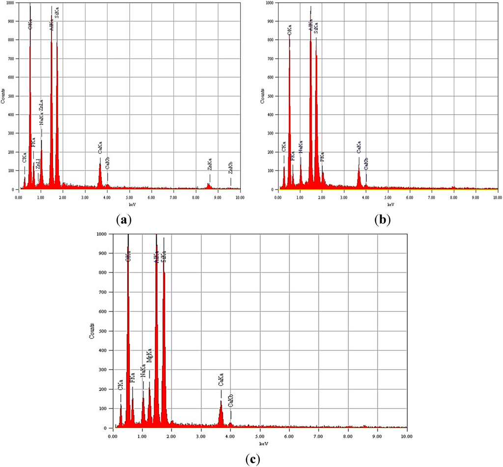
Figure 1.
(a) EDX of G 021glass; (b) EDX of G 022 glass; (c) EDX of G 023 glass.
3.1.3. FT-IR Analysis
FT-IR spectra of glasses G 021, G 022, G 023 are shown in Figure 3. Glasses possess vibrational modes characteristic of their composition and structure. The main characteristic feature of aluminosilicate glasses is the presence of Si-O-Si and Al-O-Si bonds [21]. The substitution of Si4+ by Al3+ induces more basic negative sites, thus making the glass vulnerable to attack by an acid. The negative charges are compensated for by network dwellers, i.e., mono- and bivalent cations, such as Na+ and Ca2+. The presence of these bonds is a must for the cement-forming reaction [4,21]. The assignments of bands of the glasses G 021, 022 and G 023 are listed in Table 3. Due to the amorphous nature of the glass powders, the bands observed in the investigated infrared spectra are broad. Therefore, their vibrational bands are usually not as sharp as those observed for related crystalline phases [22].
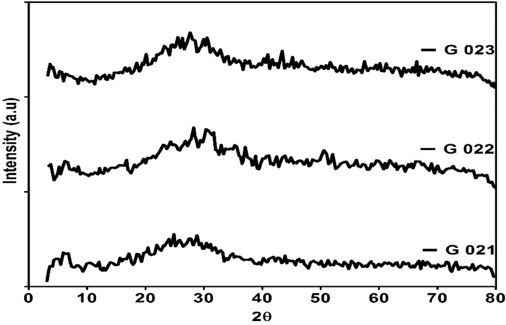
Figure 2.
XRD of G 021, G 022, and G 023 glasses.
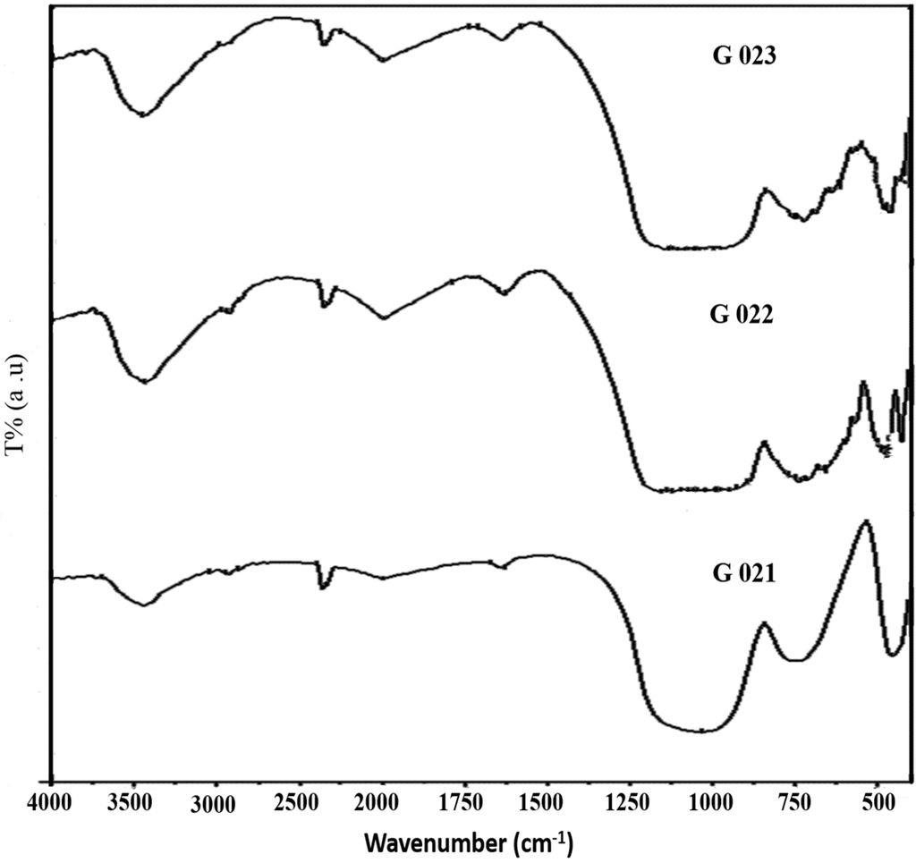
Figure 3.
FT IR of G 021, G 022, and G 023 glasses.

Table 3.
FT IR peaks G 021, G 022, and G 023 glasses (bands cm−1).
| G 021 | G 022 | G 023 | Accepted Value/Range | Assignment |
|---|---|---|---|---|
| 1030 | 1031 | 1055 | 1000–1100 | υAS Si-O-Si |
| 748 | 742 | 748 | 730 | υS Si-O-Si |
| 453 | 464 | 457 | 460 | υB Al-O-Al or Al-O-Si |
As presented in Table 3, the presence of Si-O-Si bonds were observed for all the glasses. The band at 453–464 cm−1 indicating the presence of Si-O-Si/Al-O-Si bonds and this band can be ascribed to bending mode υB. The symmetric stretching of Si-O-Si in the presence of aluminum was observed around 748 cm−1. The intense band around 1030–1055 cm−1 signifies the asymmetric stretching vibrations of Si-O-Si bonds. The values are in good agreement with those reported earlier [16,23]. The framework of AlO4 and SiO4 tetrahedra are thus established for the above glasses. From the FT IR spectra, it can be inferred that all the glasses irrespective of their processing conditions exhibited the structure required for cement formation.
3.1.4. Particle Size Analysis
Particle size distribution of glass powders G 021, G 022 and G 023 are depicted in Table 4. All the processed glass powders showed a wide distribution of particle sizes. The mean particle size of the powders is 10.48, 2.19 and 2.65 μm, respectively. The particle size data confirm the fine grain nature of the powders. The fine nature of the powders is also supported by the SEM micrographs (Figure 4). The SEM pattern of the processed glasses exhibited characteristic angular shaped irregular particles typical for powders ground by ball milling technology [24].

Table 4.
Particle size distribution of G 021, G 022, and G 023 glasses.
| Glass | Diameter at 10% d10 (µm) | Diameter at 50% d50 (µm) | Diameter at 90% d90 (µm) | Mean Diameter (µm) |
|---|---|---|---|---|
| Glass 0 21 | 1.20 | 3.89 | 35.07 | 10.48 |
| Glass 0 22 | 0.66 | 1.98 | 4.09 | 2.19 |
| Glass 0 23 | 0.87 | 2.16 | 5.21 | 2.65 |
3.2. Cement Properties
3.2.1. Initial and Final Setting Times
The setting characteristics of luting cements should allow sufficient time for mixing the material, applying it to the restoration and/or to the tooth preparation and for cementing the restoration. During the setting process, the mix changes from a fluid liquid to a hard, solid in a matter of minutes. If the cement sets too fast, viscosity increases, so rapidly that it would be impossible to cement the casting fully. On the other hand, if the setting time is too long, chair time would be prolonged unduly. As per ADA Specification No. 96 (ISO No. 9917), the setting time of luting cement should be between 2.5–8 min [25].
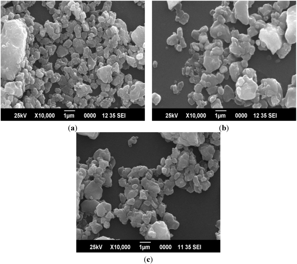
Figure 4.
(a) SEM of G 021 glass; (b) SEM of G 022 glass; and (c) SEM of G 023 glass.
There are two main factors that control the kinetics of the setting reaction. These include the extraction rate of ions from the glass, which is controlled by the composition of the glass and liquid, and the binding of cations to the polyanion chain. The number and type of anions and cations released from the glass particles will determine the extent of crosslinking of the polysalt matrix and the cement properties [26,27].
To impart radiopacity to the CAS glass, part of the Ca2+ was substituted for Zn2+, Sr2+ or Mg2+ at a 1:1 molar ratio. This partial substitution has increased the reactivity of all the glasses. In addition to this, the fine grain nature of the powder also contributed to a more rapid reaction and hence reduced initial setting time (working time). To get a suitable working time, low temperature (≈200 °C) heat treatment was performed [28]. The heat treatment could afford an additional two minutes to the existing one-minute working time, making it a convenient three minutes of working time. Figure 5 illustrates the initial and final setting times of G 021, G 022 and G 023 cements at various P/L ratios. One-way ANOVA showed significant differences in setting times at P/L ratios of 1.6/1.0 and 1.7/1.0 among the cements studied (p < 0.05).
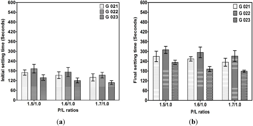
Figure 5.
(a) Initial setting time of G 021, G 022, and G 023 cements; and (b) final setting time of G 021, G 022, and G 023 cements.
The setting time of G 021 cement was found to be shorter, which could be due to the involvement of Zn2+ and Ca2+ ions during the initial stages of the cement forming reaction. G 022 cement on the other hand, exhibited delayed onset of setting after heat treatment. This is most likely due to the slow ion binding of Sr2+ to the polyacid chains. This view is vindicated by earlier investigations [29,30]. The setting time of G 023 cement was very short, which could be due the formation of magnesium polyacrylate along with calcium polyacrylate during the initial cement forming reaction [31], the fine grain nature of the powder and volumetric heating of the glass. Microwave heating conditions allowed more uniform degradation of the glass, resulting in release of cement forming cations at a faster rate. All these conditions activated the overall kinetics of the cement forming reaction of G 023 cement. This view is supported by the pH measurement of initial setting cement. G 023 cement showed more rise in the pH during the first thirty minutes of the setting reaction (Figure 6). ICP OES analysis of the set cements also showed less concentration of Ca, Al and Zn/Mg/Sr in the solution at the end of 24 h, thus confirming that these ions have reacted with polyacids to form insoluble polyacrylate matrix in the solution (Figure 7).
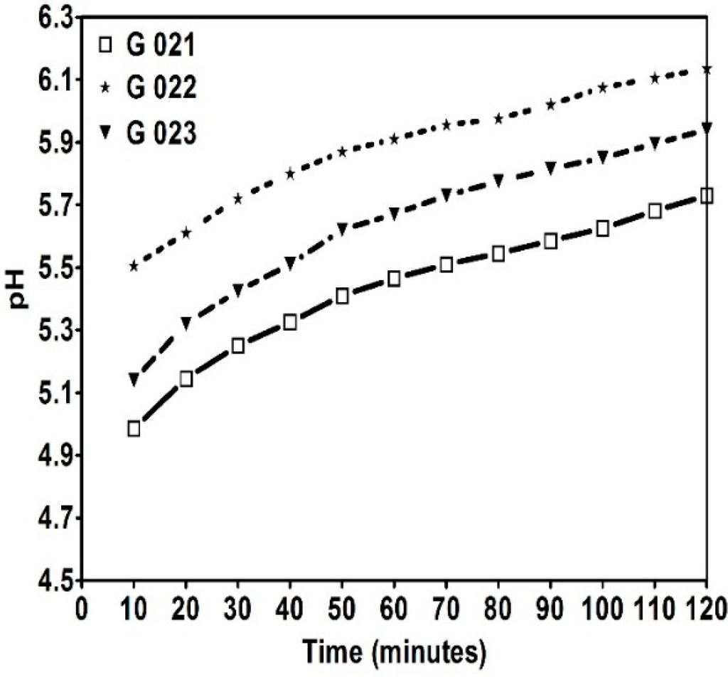
Figure 6.
pH changes of G 021, G 022, and G 023 cements during initial setting.
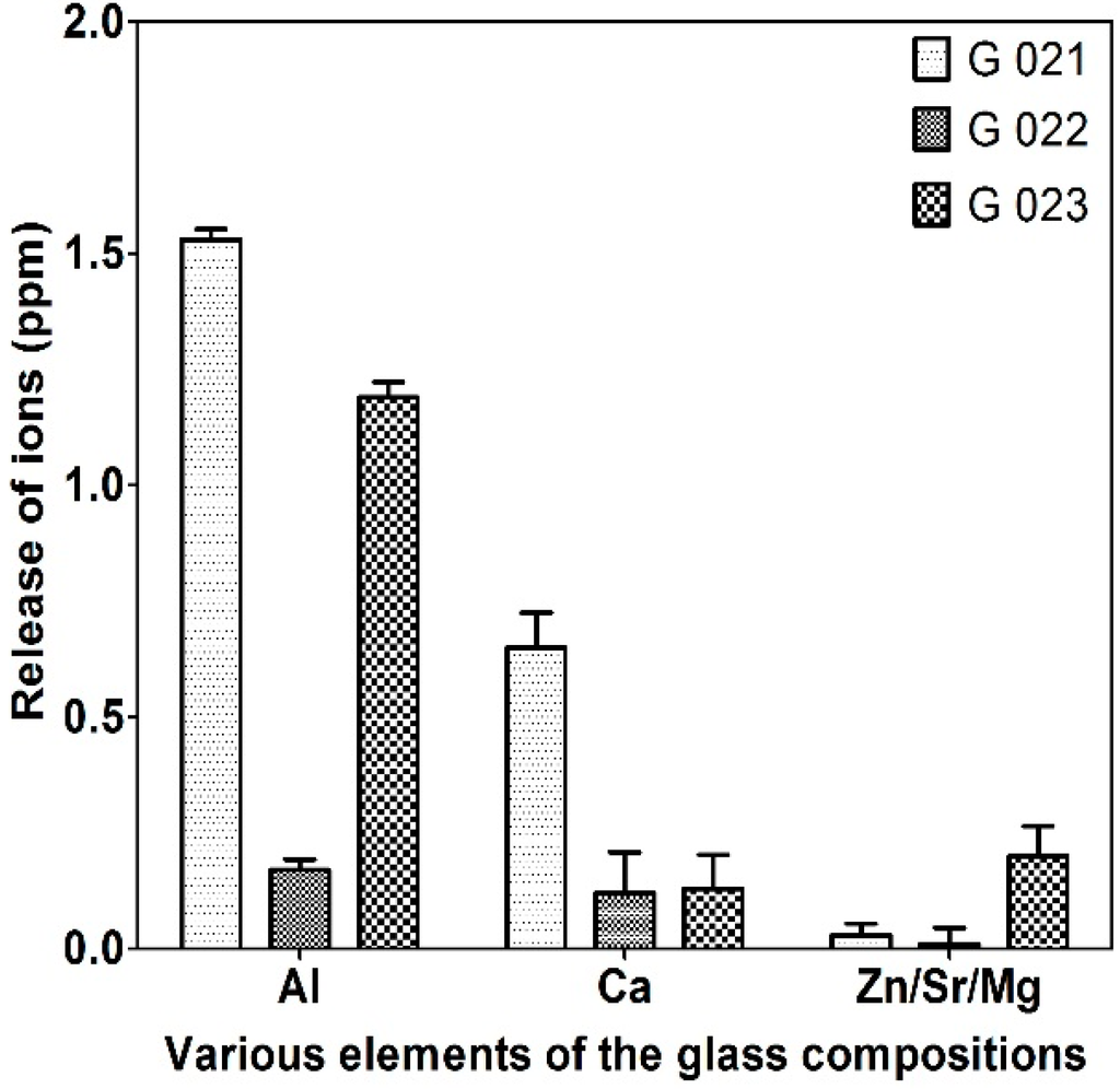
Figure 7.
ICP OES analysis of G 021, G 022, and G 023 cements at 24 h.
3.2.2. Compressive Strength
The compressive strength is very important for evaluation of dental cements because it reflects the resistance of the material to occlusion forces frequently occurring during mastication, which is clinically significant. ADA Specification No. 96 (ISO No. 9917) for dental water based cements recommends compressive strength of 70 MPa at 24 h [25]. Figure 8 shows the mean compressive strength of G 021, G 022 and G 023 cements measured at the end of 24 h and one week. One-way ANOVA did not show significant difference among the cements (p > 0.05). The compressive strength of all the cements was above the minimum specification requirements for luting cements.
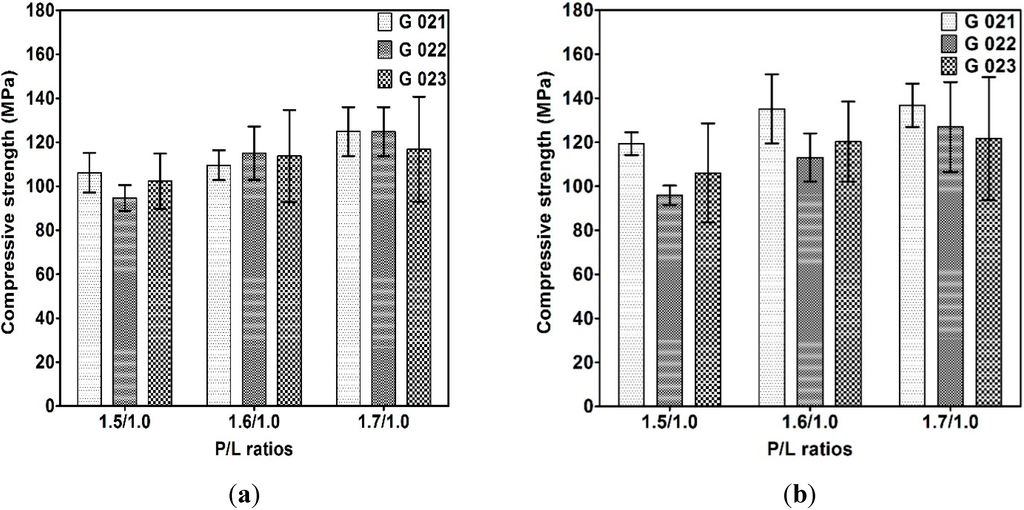
Figure 8.
Compressive strength of G 021, G 022, and G 023 cements after 24 h (a); and after one week (b).
The final mechanical properties of the cements are significantly dependent upon cross-linking formation during setting [2,4]. All the cements exhibited lower strength values at a P/L ratio of 1.5/1.0. This can be attributed to the lesser degree of cross-linking reaction due to the greater amount of polymer solution per surface area of glass [32]. Similarly, they exhibited higher strength at a P/L ratio of 1.7/1.0 but at the cost of rapid setting nature. Hence, the P/L ratio of 1.6/1.0 was considered as optimum, as this ratio provided adequate strength with ample working time for handling the cements. The strength of the cements increased with time. This could be related to the increase in the number of ionic cross-links over a period of time and further resistance to water sorption [33,34].
3.2.3. Shear Strength
The mean shear strength of G 021, G 022, and G 023 cements measured at the end of 24 h is presented in Figure 9. Statistical analysis did not show significant variation between the cements (p > 0.05). The small difference in the shear strength between the cements may be attributed to the difference in particle size distribution of the processed glass powders (Table 4). G 021 cement with the wide distribution of particles exhibited better shear strength. The rank order of shear strength is consistent with the compressive strength of cements. The result obtained in the present study is in accordance with early study [35].
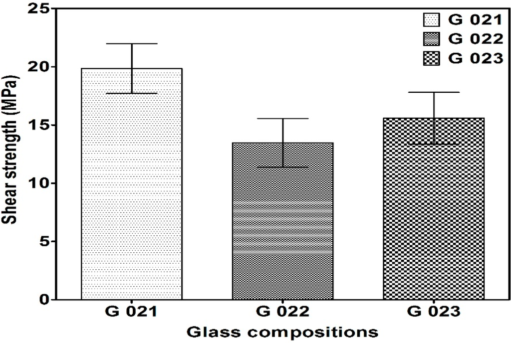
Figure 9.
Shear strength of G 021, G 022, and G 023 cements at 24 h.
3.2.4. Radiopacity
Figure 10 shows a radiographic image and relative radiodensity of G 021, G 022, and G 023 cements. One-way ANOVA showed significant differences in radiodensity among the cements (p < 0.05). In this study, G 021 and G 022 cements were radiopaque, whereas G 023 cement was radiolucent. Differences in composition appear to be the principal reason for this observation. Zinc (z = 30) and Strontium (z = 38) have high atomic numbers amongst the elements used in this study, which could explain their radiopacities. G 022 (Sr) cement exhibited better radiopacity over G 021 (Zn) cement. This observation is in accordance with earlier reports [12]. G 023 cement can be considered radiolucent. In this cement, part of Ca2+ was replaced by Mg2+. Atomic numbers of Ca2+ and Mg2+ are 20 and 12, respectively. Hence their presence would not make the glass radiopaque [12,36]. G 022 cement produced the desirable property of radiopacity without compromising the other important properties of luting cements.
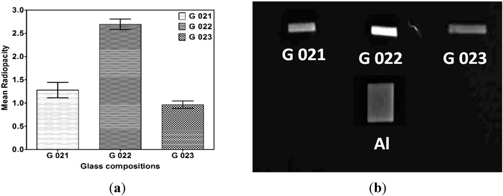
Figure 10.
(a) Mean Radiopacity of G 021, G 022, and G 023 cements; and (b) radiographic image of G 021, G 022, and G 023 cements.
4. Conclusions
In this study, calcium fluoroaluminosilicate glasses containing Zn/Sr/Mg were designed for luting applications The partial substitution of Ca2+ by Zn2+/Sr2+/Mg2+ ions increased the overall reacticity of the glasses towards polyacids. The working times and setting times of the GICs examined here are, at present, too fast for clinical use. However, cement containing Sr2+ exhibited an adequate working time and strength characteristics at an optimum P/L ratio of 1.6/1.0. The incorporation of Sr2+ and Zn2+ into the glass phase of the cements produced the most desirable property of radiopacity without compromising the other qualities of luting cements. Cements based on the conventional melt and microwave melt processed glasses did not show significant variation in their properties. Hence the microwave technology can be utilized for processing the ionomer glasses with many attractive advantages.
Acknowledgments
We are thankful to Ceramic Technological Institute, BHEL, Corp. R&D, Bangaluru, for providing the facilities for carrying out glass melting. The authors are also grateful to department of Dental Materials and Oral Medicine and Radiology, Manipal College of Dental Sciences, Manipal for providing the facilities for carrying out strength and radiopacity evaluation. The authors also acknowledge the facilities provided by Sophisticated Test and Instrumentation Centre (STIC), Cohin University of Science and Technology for glass characterization.
Author Contributions
Nagaraja Upadhya P. was predominantly responsible for all experimental works reported in this study as a part of his Ph.D thesis. The processing of materials, including microwave assisted melting and conventional glass processing was carried out at the Ceramic Technological Institute, BHEL, and Bengaluru, India under the supervision and facility utilization of L. N. Satapathy. The manuscript was written by Nagaraja Upadhya P. with assistance and review by Satapathy. K. K. Srinivasan and A. Vasudeva Adhikari supervised the cement characterization experimental procedures.
Conflicts of Interest
The authors declare no conflict of interest.
References
- Edward, E.H. Dental cements for definitive luting: A review and practical clinical considerations. Dental Clin. North Am. 2007, 51, 643–658. [Google Scholar] [CrossRef]
- Braden, M.; Clarke, R.L.; Nicholson, J.; Parker, S. Polymeric Dental Materials; Springer-Verlag: Berlin/Heidelberg, Germany, 1997. [Google Scholar]
- Smith, D.C. Development of glass ionomer cements. Biomaterials 1998, 19, 467–478. [Google Scholar] [CrossRef] [PubMed]
- Wilson, A.D.; McLean, J.W. Glass Ionomer Cement; Quintessence Publishing Co.,Inc.: Hanover Park, IL, USA, 1988. [Google Scholar]
- McKinney, J.E.; Antonucci, J.M.; Rupp, N.W. Wear and microhardness of silver sintered glass ionomer cement. J. Dent. Res. 1988, 67, 831–835. [Google Scholar] [CrossRef] [PubMed]
- Griffin, S.G.; Hill, R.G. Glass composition influence on glass polyalkenoate cement mechanical properties. J. Non Cryst. Solids 1996, 196, 255–259. [Google Scholar] [CrossRef]
- Kent, B.E.; Lewis, B.G.; Wilson, A.D. Glass ionomer cement formulations: I. The preparation of novel fluoroaluminosilicate glasses high in fluorine. J. Dent. Res. 1979, 58, 1607–1619. [Google Scholar] [CrossRef] [PubMed]
- Mount, G.J. Glass ionomer cements: Past, present and future. Oper. Dent. 1994, 19, 82–90. [Google Scholar] [PubMed]
- De la Macorra, J.C.; Pradies, G. Conventional and adhesive luting cements. Clin. Oral Investig. 2002, 6, 198–204. [Google Scholar]
- Attar, N.; Tam, L.E.; McComb, D. Mechanical and physical properties of contemporary dental luting cements. J. Prosthet. Dent. 2003, 89, 127–134. [Google Scholar] [CrossRef] [PubMed]
- Rosenstiel, S.F.; Land, M.F.; Crispin, B.J. Dental luting agents: A review of the current literature. J. Prosthet. Dent. 1998, 80, 280–301. [Google Scholar] [CrossRef] [PubMed]
- Tsuge, T. Radiopacity of conventional, resin modified glass ionomer, and resin based luting materials. J. Oral Sci. 2009, 15, 223–230. [Google Scholar] [CrossRef]
- Bertolini, M.J.; Zaghete, M.A.; Gimenes, R.; Padovani, G.C.; Cruz, C.A.S. Preparation and evaluation of an experimental luting glass ionomer cement to be used in dentistry. J. Mater. Sci. 2009, 20, 1781–1785. [Google Scholar]
- Bertolini, M.J.; Regina, G.P.D.; Zaghete, M.A.; Gimenes, R. Evaluation of glass ionomer cements properties obtained from niobium silicate glasses prepared by chemical process. J. Non-Cryst. Solids 2005, 351, 466–471. [Google Scholar] [CrossRef]
- Cestari, A.; Bandeira, L.C.; Calefi, P.S.; Nassar, E.J.; Ciuffi, K.J. Preparation of calcium fluoroaluminosilicate glasses containing sodium and phosphorus by the nonhydrolytic sol–gel method. J. Alloys Comp. 2009, 472, 299–306. [Google Scholar] [CrossRef]
- Bertolini, M.J.; Zaghete, M.A.; Gimenes, R.; Raphael, F.D.; Vaz, L.G. Preparation of new glass systems by the polymeric precursor method for dental applications. J. Non-Cryst. Solids 2004, 344, 170–175. [Google Scholar] [CrossRef]
- Subrata, S.; Ram Mohan, V.C.; Delregno, G.E. Method of Microwave Processing Ceramics and Microwave Hybrid Heating System for Same. US 2007/0023971 A1, 1 February 2007. [Google Scholar]
- American National Standard/American Dental Association. Specification No. 96, Dental Water Based Cements; American National Standard/American Dental Association: Chicago, IL, USA, 1995. [Google Scholar]
- Boyd, D.; Towler, M.R.; Watts, S.; Hill, R.G.; Wren, A.W.; Clarkin, O.M. The role of Sr2+ on the structure and reactivity of SrO–CaO–ZnO–SiO2 ionomer glasses. J. Mater. Sci. 2008, 19, 953–957. [Google Scholar]
- Wren, A.; Clarkin, O.M.; Laffir, F.R.; Ohtsuki, C.; Kim, I.Y.; Towler, M.R. The effect of glass synthesis route on mechanical and physical properties of resultant glass ionomer cements. J. Mater. Sci. 2009, 20, 1991–1999. [Google Scholar]
- De Maeyer, E.A.P.; Verbeeck, R.M.H.; Vercruysse, C.W.J. Reactivity of fluoride-containing calcium aluminosilicate glasses used in dental glass-ionomer cements. J. Dent. Res. 1998, 77, 2005–2011. [Google Scholar] [CrossRef] [PubMed]
- Chen, W.S.; Monroe, E.A.; Condrate, R.A.; Guo, Y.M. An investigation of the hardening process for several phosphate glass—Containing cements. J. Mater. Sci. 1993, 4, 111–116. [Google Scholar]
- De Maeyer, E.A.P.; Verbeeck, R.M.H.; Vercruysse, C.W.J. Infrared spectrometric study of acid-degradable glasses. J. Dent. Res. 2002, 81, 552–555. [Google Scholar] [CrossRef] [PubMed]
- Gu, Y.W.; Yap, A.U.J.; Cheang, P.; Kumar, R. Spheroidization of glass powders for glass ionomer cements. Biomaterials 2004, 25, 4029–4035. [Google Scholar] [CrossRef] [PubMed]
- Powers, J.M.; Sakaguchi, R.L. Craig’s Restorative Dental Materials, 12th ed.; Mosby: Maryland Heights, MO, USA, 2006. [Google Scholar]
- Crisp, S.; Merson, S.A.; Wilson, A.D. Modification of ionomer cements by the addition of simple metal salts. Ind. Eng. Chem. Prod. Res. Dev. 1980, 19, 403–408. [Google Scholar] [CrossRef]
- Barra, E.D.; Hill, R.G. Influence of alkali metal ions on the fracture properties of glass polyalkenoate (ionomer) cements. Biomaterials 1998, 19, 495–502. [Google Scholar] [CrossRef] [PubMed]
- Neve, A.D.; Piddock, V.; Combe, E.C. The effect of glass heat treatment on the properties of a novel polyalkenoate cement. Clin. Mater. 1993, 12, 113–115. [Google Scholar] [CrossRef] [PubMed]
- Deb, S.; Nicholson, J.W. The effect of strontium oxide in glass—Ionomer cements. J. Mater. Sci. 1999, 10, 471–474. [Google Scholar]
- Boyd, D.; Towler, M.R. The effect of strontium on the rheology and mechanical properties of Zinc based glass polyalkenoate cements. Eur. Cells Mater. 2006, 11, 26. [Google Scholar]
- Crisp, S.; Prosser, H.J.; Wilson, A.D. An infrared spectroscopic study of cement formation between metal oxides and aqueous solutions of poly (acrylic) acid. J. Mater. Sci. 1976, 11, 36–48. [Google Scholar] [CrossRef]
- Prentice, L.H.; Tyas, M.J.; Burrow, M.F. The effect of particle size distribution on an experimental glass-ionomer cement. Dent. Mater. 2005, 21, 505–510. [Google Scholar] [CrossRef] [PubMed]
- Angeles, M.; Lorente, C.; Godin, C.; Meyer, J.M. Mechanical behavior of glass ionomer cements affected by long term storage in water. Dent. Mater. 1994, 10, 37–44. [Google Scholar] [CrossRef] [PubMed]
- Piwowarczyk, A.; Lauer, H.C. Mechanical properties of luting cements after water storage. Oper. Dent. 2003, 28, 535–542. [Google Scholar] [PubMed]
- Yamazaki, A.; Hibino, Y.; Honda, M.; Nagasawa, Y.; Hasegawa, Y.; Omatsu, J.; Yamaga, T.; Nakajima, H. Effect of water on shear strength of glass ionomer cements for luting. Dent. Mater. J. 2007, 26, 708–712. [Google Scholar] [CrossRef] [PubMed]
- Fonseca, R.B.; Branco, C.A.; Soares, P.V.; Correr-Sobrinho, L.; Haiter-Neto, F.; Fernandes-Neto, A.J.; Soares, C.J. Radiodensity of base, liner and luting dental materials. Clin. Oral Investig. 2006, 10, 114–118. [Google Scholar] [CrossRef] [PubMed]
© 2015 by the authors; licensee MDPI, Basel, Switzerland. This article is an open access article distributed under the terms and conditions of the Creative Commons Attribution license (http://creativecommons.org/licenses/by/4.0/).