1. Introduction
A significant development in adjustable-speed electric drives is the adoption of multiphase electric machines, achieved by increasing the number of stator winding phases from the conventional three-phase configuration to structures with 5, 6, or more phases.
This development is driven by increasingly stringent requirements for energy efficiency, power density, reliability, and continuity of operation in electric drive systems [
1,
2]. For the same total power, using a larger number of phases reduces the current per phase compared with an equivalent three-phase machine and alleviates the thermal and electrical stresses imposed on the power-electronic converter components, while providing additional redundancy. Further benefits include reduced vibration, magnetic noise, and torque ripple, together with additional degrees of freedom for variable-speed control. Consequently, multiphase machines can maintain temporary operation after an open-phase fault with a reduced number of energized phases, including operation with only one active three-phase winding set [
2,
3,
4,
5].
These characteristics have promoted the use of multiphase machines in electric vehicles, marine propulsion systems, oil and gas installations, wind-energy conversion systems, and aerospace applications, where continuity of operation is often an essential requirement [
1,
2]. Their practical relevance is also demonstrated by existing commercial implementations. Dana TM4 offers high-voltage motor-and-inverter systems in three-, six-, and nine-phase configurations, including the SUMO™ MD and SUMO™ HP product lines, with peak power ratings of 170–300 kW and 430–540 kW, respectively, for commercial vehicles and bus platforms [
3]. Tron Energy employs a 230 kW multiphase permanent-magnet synchronous machine in its 9 and 11 m electric buses [
4]. Another representative example is the Dark Matter motor developed by Koenigsegg for the Gemera. It employs a six-phase Raxial Flux architecture and delivers 800 hp, approximately 600 kW, and 1250 N·m at a mass of 39 kg, corresponding to a gravimetric power density of approximately 15.3 kW/kg [
5].
Owing to their favorable balance between structural complexity and electromagnetic performance, six-phase electrical machines represent one of the most attractive compromises among multiphase configurations. In these machines, the stator winding can be implemented as two three-phase sets arranged with an electrical displacement
of 0°, 30°, or 60° between the magnetic axes of the corresponding phases. These arrangements are commonly referred to as a dual three-phase configuration for
, an asymmetrical six-phase configuration for
, and a symmetrical six-phase configuration for
. The selected displacement angle determines the topological and electromagnetic characteristics of the winding and influences the spatial distribution of the magnetomotive force [
2].
The stator winding is a fundamental component of any electric machine, as it facilitates the formation of the air-gap magnetic field and the electromechanical energy conversion. The motor’s energy efficiency, dynamic performance, and reliability are heavily dependent on the winding topology, the distribution of coils in the slots, the winding pitch, and its structural integrity.
A fundamental quantity characterizing the electromagnetic performance of a stator winding is the magnetomotive force (MMF). In the study of the MMF produced by multiphase stator windings, both analytical and numerical methods are employed, depending on the objective of the investigation. Analytical methods [
6,
7] provide explicit mathematical relationships between the magnetomotive force, the parameters of the multiphase winding, and its harmonic content. These methods require relatively low computation time, facilitate the preliminary analysis and optimization of the winding topology, provide clear physical insight into the electromagnetic phenomena, and are particularly useful during conceptual design. However, their application is generally based on simplifying assumptions, such as a uniform air gap, linear material behavior, and an idealized geometry. Numerical methods [
8,
9] are employed during the design and validation stages because they allow the spatial distributions of the magnetic field and MMF to be reproduced while considering the actual geometry and operating conditions of the electrical machine. These methods require specialized software and considerable computational resources, are applied to a machine with a specific geometry and topology, and provide a less intuitive physical interpretation of the results. The general principles of induction machines and multiphase electric drives are discussed in [
10,
11], whereas fault-tolerant operation under single- or multiple-phase open-circuit conditions is analyzed in [
12,
13,
14].
Although numerous winding types initially developed for three-phase machines can be adapted for six-phase induction machines, the transition from three to six phases introduces specific challenges, particularly regarding the reduction in the number of slots per pole and phase (q) and the increased harmonic content of the magnetomotive force (MMF) in certain configurations [
15,
16,
17].
While the study of three-phase induction machine windings is well-established in classical works [
18,
19,
20,
21,
22,
23], the systematic analysis of six-phase configurations remains relatively limited and fragmented. Most existing publications focus on specific case studies or the optimization of converter control systems under fault conditions [
24,
25,
26,
27]. Computer-based analysis of winding factors, MMF space harmonics, and differential leakage coefficients in multiphase machines is presented in [
28]. However, these approaches often present significant gaps: some provide rigorous experimental validation but are restricted to normal operating regimes [
26], while others lack a generalized methodology for evaluating diverse topologies [
27].
Furthermore, research on fault tolerance frequently focuses on converter control strategies, often overlooking the impact of spatial harmonics generated by the specific winding configuration. Even sophisticated matrix synthesis methods for MMF polygons, though theoretically robust, are primarily oriented toward three-phase systems and require substantial adaptation for six-phase machines [
29]. Consequently, the current literature lacks a unified framework that treats, in a comparative and integrated manner, the influence of winding topology on both magnetic field quality and operational robustness under power supply fault conditions.
In this context, the present paper aims to highlight the intrinsic potential of six-phase induction machines from the perspective of stator winding structure, emphasizing enhanced fault tolerance and improved air-gap magnetic field quality. The primary objective of this research is the comparative analysis of several topological variants of six-phase windings and their evaluation based on a winding quality factor, determined through a combined analytical–graphical methodology.
The proposed methodology integrates the theoretical analysis of electromagnetic parameters, the use of the MMF polygon to assess the harmonic content of the magnetic field, and the interpretation of results relative to practical requirements for both nominal and post-fault operation. Based on the calculated quality factor values, a classification of the studied topologies is established, enabling the formulation of concrete recommendations for stator winding selection in the design of six-phase induction machines for industrial and traction applications.
The originality of this paper does not lie in the Krondl method or the Görges/MMF polygon representation, which are established analytical tools, but in the integration of four components within a unified framework: topological classification, homologous-series theory, MMF-polygon-based evaluation, and analysis of operation with only one active three-phase winding set. The proposed methodology establishes a direct relationship between the winding topology, the MMF harmonic spectrum, and the capability to operate with a single three-phase set, providing a relatively simple, interpretable, and useful tool for the preliminary design stage. Compared with the preliminary conference paper [
30], the present study extends the comparative analysis to nine six-phase winding topologies and includes experimental validation of the results.
2. Selection of the Base Model
To evaluate the electromagnetic properties of an induction machine, it is essential to determine the order and amplitude of the magnetic field harmonics in the air gap, quantities that depend heavily on the topological structure of the stator winding. In the study, comparison, and classification of windings with different pole numbers and varied topological structures, it is customary to relate them to specific base models defined according to the principles of homology developed in the literature [
20,
21,
31,
32].
According to these principles:
Windings related to a base model are electromagnetically equivalent, regardless of the number of pole pairs ().
Any winding with concentric coils can be equated to a winding with identical coils that generates an equivalent magnetic field.
A winding with different phase-zone widths can be replaced by a winding with equal phase-zone widths through appropriate pitch shortening (chording).
Windings that can be reduced to the same base structure form a homologous series, exhibiting identical electromagnetic properties.
Consequently, analyzing a limited number of base winding models is sufficient, as the relationships derived for them remain valid for all derived homologous structures. This approach is widely used in the study of three-phase windings and constitutes the methodological foundation of the proposed analysis.
A six-phase induction machine is generally treated as a dual three-phase machine, consisting of two identical three-phase windings connected in star, with either a common or separate neutral point [
10,
11,
30]. The three-phase sets can be arranged in the stator slots with an angular displacement of 60° (
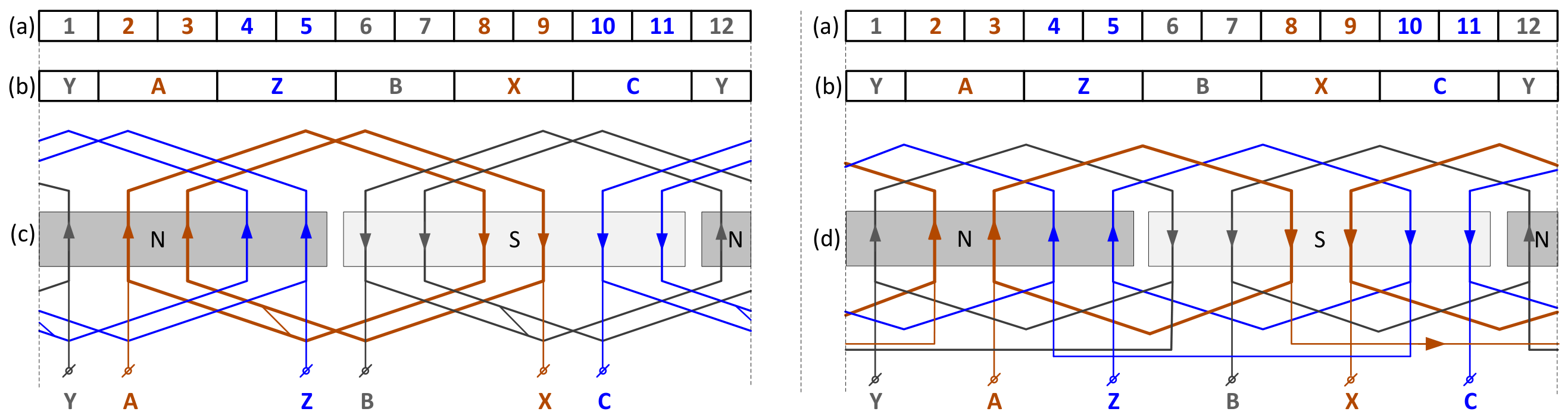
Figure 1) or 30° electrical, resulting in symmetrical winding (SW) or asymmetrical winding (ASW) structures, respectively.
Considering these concepts, the base models for generating homologous series of six-phase windings were synthesized starting from a three-phase model with a simple topology, characterized by: number of pole pairs
, number of slots per pole and phase
, single-layer configuration (
), a unique winding direction, and full-pitch coils (
). The layout of this model is shown in
Figure 1a.
The winding forms two poles and consists of six phase zones, denoted as A, B, C for the forward active parts and X, Y, Z for the return active parts (
Figure 1b). The width of each phase zone is 60° electrical. In this case, electrical angles coincide with mechanical angles since
and
. The choice of the starting slot for the first phase is arbitrary, with only the phase sequence and phase zone widths being fixed.
Each phase coil is composed of two sections, each having a number of turns N
c corresponding to one slot. In the end-winding region, the sections can be formed in the same direction or in opposite directions (e.g., camber configuration,
Figure 1d), without influencing the electromagnetic processes within the air gap.
Figure 2 illustrates the developed winding diagram of the double-layer configuration, featuring a two-plane end-winding arrangement—a solution commonly adopted in the design of three-phase machines. In this case, half of the winding sections have their sides oriented (for example) to the left, and the other half are oriented to the right.
Although double-layer windings consist of twice sides, as many coils as single-layer designs, the number of turns per coil is halved, and each slot accommodates two sides of the coil. From an electromagnetic perspective, the presented winding scenarios are equivalent; the distinctions between them are strictly technological in nature.
3. Basic Topological Structures and Homologous Series of Six-Phase Windings
The topology of a six-phase winding can be derived through simple constructive operations applied to the three-phase winding accepted as the base model, designed according to fundamental winding design principles. A representative example is the division into two equal parts of each coil group forming a phase of the single-layer three-phase winding (
Figure 1). Through this operation, two distinct sets are obtained, each consisting of three coil groups, mutually displaced by 120° electrically. Connecting each set in a star configuration results in two independent three-phase systems (A1–B1–C1 and A2–B2–C2), with separate neutral points. In this configuration, the phase belt width is reduced to 30° electrical, and the number of slots per pole and phase, q, is halved relative to the base three-phase model. To maintain the rated voltage value, the number of turns in each coil section must be correspondingly doubled. The phase zone sequence for this structure is presented in
Table 1, in the row corresponding to model T1, [
30].
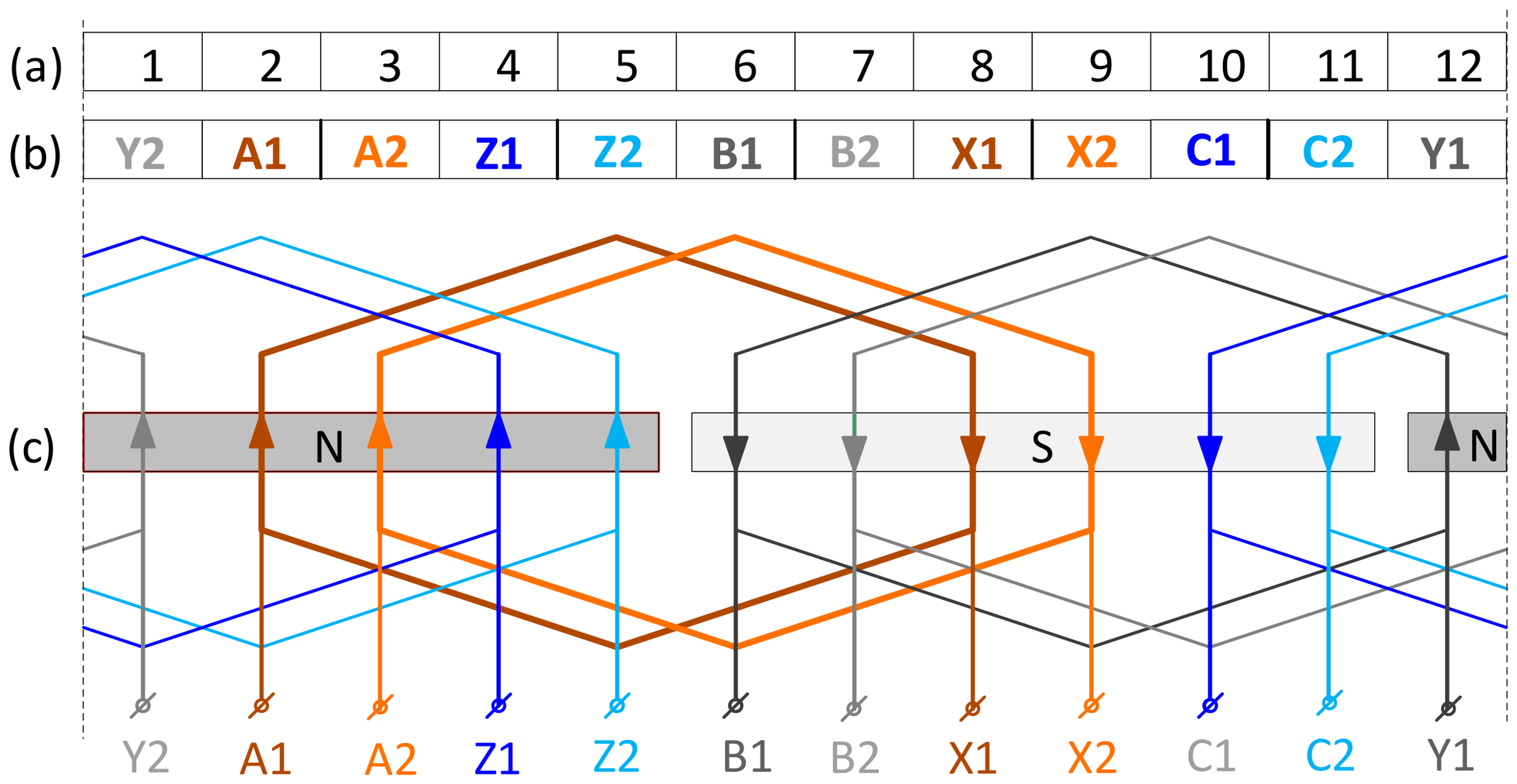
The developed layout of the single-layer six-phase winding, obtained by transforming the three-phase model from
Figure 1c, is presented in
Figure 3. In this case, a phase belt is compactly represented by a single coil side placed in a single slot (
q = 1). However, a phase belt may include two or more coils arranged in adjacent slots and connected in series, depending on the value of the parameter q. It can be observed that the homologous phases of the two three-phase sets are spatially displaced by 30° electrical degrees, resulting in an asymmetrical winding (ASW) structure characterized by an angular shift between sets of
θ = 30° electrical degrees.
Through a similar procedure, the symmetrical six-phase winding model can be obtained, with an angular shift of
θ = 60° electrical, corresponding to the T2 structure in
Table 1. For comparison, the matrix of the three-phase winding accepted as the base model (
Figure 1a) is presented in
Table 1 (row designated T0).
Double-layer windings contain twice the number of coils (elementary coils) compared to single-layer windings, while also offering a higher degree of design flexibility. This structure allows for several modification techniques, such as pitch shortening (chording), doubling the phase belt width, or modifying the phase sequence.
Table 1 presents the phase belt matrices for seven variants of double-layer windings, selected as base models for generating homologous series of six-phase windings. Among these, four variants feature a full pitch (T3–T6), and three variants feature a shortened pitch (T7–T9).
The following notations are used in the table:
W6F—Six-phase winding;
Tn—Model index;
DP—Diametrical pitch (full pitch);
PSh—Shortened pitch (chorded pitch), ;
SL—Single-layer;
DL—Double-layer;
QSL—Quasi-single layer;
DTP—Double three-phase (θ = 0°);
DPA—Double phase area;
Z/Z—Zig-zag;
PAW—Phase area width (phase belt);
SYM/ASYM—Symmetrical and asymmetrical structures, respectively.
PZW = 0°/30°/60° (phase zone width).
A brief description of these structures is provided below, focusing on the definition of the winding factor:
T3—Quasi-single-layer double-layer winding: characterized by a phase belt width of 30° electrical, with sections arranged in slots and connected in series or parallel. Electromagnetically, this structure is equivalent to the single-layer winding T1.
T4—Symmetrical double-layer winding: features a full pitch and a double phase area. The active “go” sides (AGS) of the coils are located in adjacent slots in the upper layer, while the active “return” sides (ARS) are placed in the lower layer. The angular displacement between the three-phase sets is electrical.
T5—Symmetrical dual-three-phase winding: structurally similar to T4, with the distinction that the angular displacement between the two three-phase sets is electrical.
T6—Symmetrical double-layer winding: features a full pitch and a double phase area in a zig-zag configuration. The active sides of adjacent coils belonging to the same phase are alternately arranged in the two layers; thus, one coil has its “go” side in the upper layer and its “return” side in the lower layer, while the subsequent coil is arranged inversely.
T7—Quasi-single-layer double-layer winding: features a shortened pitch. The phase winding coils span poles and are considered camber-type. The structure is symmetrical, with an angular displacement electrical and .
T8—A symmetrical double-layer winding employing a short-pitched coil and a 30° electrical phase-belt width. Although its topology closely resembles that of the T3 configuration, the lower layer is shifted laterally by slot pitches, corresponding to one phase-belt width. This modification introduces a 0° electrical displacement between the magnetic axes of the two three-phase winding sets. From an equivalent winding perspective, the topology may be regarded as a short-pitched winding with a coil-pitch factor of .
T9—Asymmetrical double-layer winding: features a double phase area and a separate layer arrangement for the two three-phase sets. From an electromagnetic analysis perspective, the structure can be considered a monopolar winding for each set, characterized by and .
In all nine scenarios, the winding is assumed to be a chain winding consisting of 12 identical coils with equal spans and a single winding direction. Each phase winding comprises two series-connected coils, placed either in the same slots across two layers or in adjacent slots (in the same or different layers, as applicable). The coil starts are considered the active “go” sides (denoted A, B, C), while the “return” sides (denoted X, Y, Z) signify the coil ends. The alphanumeric symbols for the coils also include a digit defining the winding set number and a numeric index for the coil sequence (e.g., Z12—end of the second coil of phase C from set 1). The phase belt matrix for each model indicates the starts and ends of the coils. The coils of a phase winding are connected in series (e.g., (A11 –X11) + (A12–X12).
Furthermore, the winding models in
Table 1 are developed for a bipolar machine (2
p = 2) with a 12-slot stator core. Based on the models in
Table 1, various homologous series can be developed [
20,
31] following the fundamental principles of homology. For instance, windings with 4, 6, 8, or more poles are obtained using the “by addition” principle, where the bipolar winding is repeated
p times in series or parallel. While the mechanical angles change by a factor of
, the electrical angles and the fundamental characteristics of the air-gap magnetic field remain identical. Another example of forming a homologous series involves varying the parameter q. If
, the phase winding consists of q coils placed in adjacent slots within the phase belt limits, forming series-connected coil groups.
Based on the aforementioned base models, an automated system for the synthesis and analysis of six-phase windings can be developed, following the methodology used for three-phase systems [
29,
33].
4. Performance Evaluation of Six-Phase Windings Based on the Quality Factor
4.1. The Application of Krondl’s Methodology for Six-Phase Winding Assessment
The primary function of the induction machine’s stator winding is to generate a rotating magnetic field in the air gap with a waveform as close as possible to a sine wave, thereby minimizing the harmonic content. Higher-order harmonics induce parasitic effects that degrade the machine’s operational performance, such as reducing efficiency through stray load losses, deteriorating starting characteristics [
30,
34], and increasing vibration and noise levels.
The most significant higher-order harmonics are the space harmonics, which result from the discrete, non-sinusoidal distribution of the winding along the air gap [
15,
16,
20,
35]. Based on these considerations, for a generalized assessment and objective classification of the six-phase winding models selected above, the use of the Winding Quality Factor is proposed. This indicator is defined through Krondl’s methodology, utilizing the Magnetomotive Force (MMF) Polygon (commonly referred to as the Görges Polygon).
Krondl’s method is extensively applied in the analysis of three-phase windings [
19,
20,
21,
25,
29,
33], providing a robust geometric framework for evaluating the differential leakage coefficient.
4.1.1. Definition and Physical Significance of the Winding Quality Factor ()
The Winding Quality Factor (
) is a relative quantity that compares the magnetic field energy created by the machine’s polyphase winding, integrated over the entire harmonic spectrum (
), with the portion of the magnetic field energy attributed to the fundamental harmonic (
). This indicator does not take into account the influence of factors such as the saturation of the ferromagnetic circuit elements or the air-gap non-uniformity caused by slot openings; however, it reflects the major changes in the harmonic structure of the machine’s magnetic field directly related to the winding topology. From this definition, the following calculation relationship for the quality factor results:
It can be demonstrated [
19,
20] that the energy ratio in Equation (1) can be substituted by the ratio of the polar radius of inertia of the MMF polygon (
) to the radius of inertia of the circular diagram (
), plotted for the fundamental harmonic of the MMF wave in the air gap. Thus:
The construction procedure of the MMF diagram and the calculation of the radii of inertia (, ) are exemplified through the case studies of the six-phase windings selected from the list highlighted above.
4.1.2. Case Study 1. Symmetrical Six-Phase Single-Layer Winding—Model T2
The first analysis focuses on the symmetrical six-phase single-layer winding, designated as Model T2 (see
Table 1). The design parameters are
,
,
,
,
,
, and
. The prescribed phase sequence is A1–Z1–A2–Z2–B1–X1–B2–X2–C1–Y1–C2–Y2, where the phase zone width corresponds to 30° electrical.
Phase Zone Matrix and Current Phasor Diagram
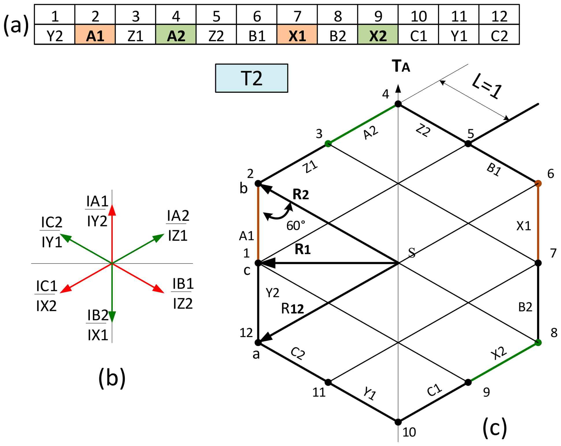
Initially, the phase zone matrix of the winding is completed (totaling
zones), following the specified phase sequence (
Figure 4a). Subsequently, the current phasor diagram is constructed (
Figure 4b).
The current phasor of the primary phase (e.g., A1) is oriented along the ordinate axis and conventionally coincides with the time axis TA. It should be noted that the phase shift between phasors, , expressed in radians or degrees, is equal to the displacement between two adjacent phase zones, expressed in electrical degrees.
Furthermore, the analysis takes into account that , , and , regardless of the slot index in which the respective active coil sides are located. The phasors are labeled using the corresponding markers of the phase zones.
MMF Polygon Construction and Analysis
For plotting the sides of the MMF polygon (
Figure 4c), the unit length is defined as the maximum value of the total current in the conductors of a single slot:
. Here, I represent the RMS value of the phase current, and is the number of conductors (turns) per slot.
Each side of the polygon corresponds to one phase zone per pole and has a length of units. The side is oriented along the direction of the current vector in the respective phase sections. On each side, nodes (points) are marked, corresponding to the slots in which the respective sections of the phase winding are located.
In the case under consideration, the winding has 12-unit phase zones (), but the polygon appears as a hexagon. This is due to the fact that some sides (in pairs of two) coincide in direction; the sections corresponding to these sides are traversed by phase currents from different sets but with identical phasors (e.g., and ).
The polar radius of inertia of the MMF polygon is determined as the mean of the squared radii of
nodes identified on its perimeter (including both vertex nodes and those located on the sides):
Geometric Calculation Methodology
Typically, a grid of lines parallel to the current phasors is superimposed over the MMF polygon to simplify the determination of the radii of inertia. This grid forms right-angled triangles or triangles with apex angles of 30°, 60°, or 120°.
For each node of the MMF polygon, a suitable triangle is selected, which encompasses the node’s radius of inertia and two sides of known length (expressed in relative units). The length of the radius of inertia is then calculated from this triangle based on the law of cosines.
Numerical Results for Case Study 1 (Symmetrical Winding T2)
In the case under consideration (
Figure 4), the MMF diagram is a regular symmetric polygon consisting of 6 identical sectors that repeat every 60°. Consequently, it is sufficient to determine only the radii
and
from the equilateral triangle ΔabS (
Figure 4c).
The side ab and the radius
have lengths equal to 2 units. The length of radius
, according to the law of cosines, is:
The square of the polar radius of inertia of the MMF polygon (
) is calculated as:
Fundamental Harmonic and Quality Indicator
The winding factor
and its components, namely the distribution factor
and the short-pitch factor
, are calculated using the well-established expressions given below:
where
is the number of slots per pole per phase; m is the number of phases;
is the electrical angular pitch between two adjacent slots; and
is the relative coil pitch, defined as the ratio of the coil pitch
to the pole pitch
.
For the case considered, the winding factor for the fundamental harmonic is determined considering that for
, the distribution factor
. For a relative coil pitch of
β = 5/6, the pitch factor is.
Thus, the total winding factor is:
The radius of inertia for the fundamental harmonic circle is given by [
19]:
It is noted that the product in Equation (7) represents the perimeter of the MMF polygon, while is the circumference of the circle representing the fundamental harmonic. The coefficient acts as a reduction factor of the fundamental MMF resulting from pitch shortening and/or the distribution of phase winding sections in slots.
The Winding Quality Indicator is thus:
Conclusions of the Case Study
Therefore, the analyzed winding has an acceptable quality indicator value, but it is far from ideal (where = 0.255% for ).
Specific nuances arise during the construction of the MMF polygon and the calculation of inertia radii for double-layer windings, especially regarding pitch shortening. Two examples of windings from this category are considered next.
4.1.3. Case Study 2. Symmetrical Six-Phase Double-Layer Winding—Model T7
The second study examines the symmetrical six-phase double-layer winding, designated as Model T7 (refer to
Table 1). The design parameters for this configuration are:
, phase zone width
electrical, and a relative coil pitch of
.
The phase sequence is A1–A2–B1–B2–C1–C2, featuring a 60° electrical displacement between the two three-phase sets.
The phase zone matrix, the current phasor diagram, and the MMF polygon are presented in
Figure 5. It is important to note that each phase winding consists of two sections, each having a number of turns
. The initial active sides (the “go” direction) of these sections are placed within a single slot in a double-layer arrangement.
Winding Factor and Quality Indicator
For this configuration, the total winding factor
is calculated as the product of the distribution factor
and the pitch factor
:
The radius of inertia for the fundamental MMF harmonic circle (
) for the double-layer configuration is calculated as follows:
The polygon perimeter (
) is 24 units. It should be noted that for double-layer windings, the perimeter calculation considers the arithmetic sum of the currents in the slot [
19].
Based on these values, the Winding Quality Indicator (
) for Model T7 (
) is determined as follows:
4.1.4. Case Study 3. Complex Double-Layer Shortened-Pitch Winding—Model T9
This case study is dedicated to a complex double-layer shortened-pitch winding, designated as Model T9 (see
Table 1). A generalized methodology for defining the quality factor is developed here, based on the calculation of axial moments of inertia. The proposed methodology involves the following computational steps:
S1. Based on the phase current phasor diagram and the phase zone matrix, the MMF polygon is plotted using the vector summation method.
S2. An arbitrary node of the MMF polygon (e.g., node no. 1) is defined as the origin through which a Cartesian coordinate system is drawn. The ordinate axis () is oriented along the time axis (e.g., the direction of phasor ().
S3. The coordinates () of the nodes corresponding to the stator armature slots are defined.
S4. The values of the moments of inertia of the nodes relative to the
and
axes, respectively, are defined as follows:
where
represents the current load in the slot, expressed in conventional units (
). It is assumed that all coil sections in the slots carry the same amount of current.
S5. The coordinates of the center of gravity (centroid) of the polygon (
,
) are calculated within the
coordinate system:
S6. The polar radius of inertia of the polygon relative to its center of gravity is determined using the parallel axis theorem (Huygens–Steiner theorem):
where
represents the total current mass of the nodes.
S7. The radius of inertia for the fundamental harmonic () is calculated according to Equation (7).
S8. The winding quality factor is determined using Equation (2).
Geometric Interpretation of the MMF Polygon (Figure 6)
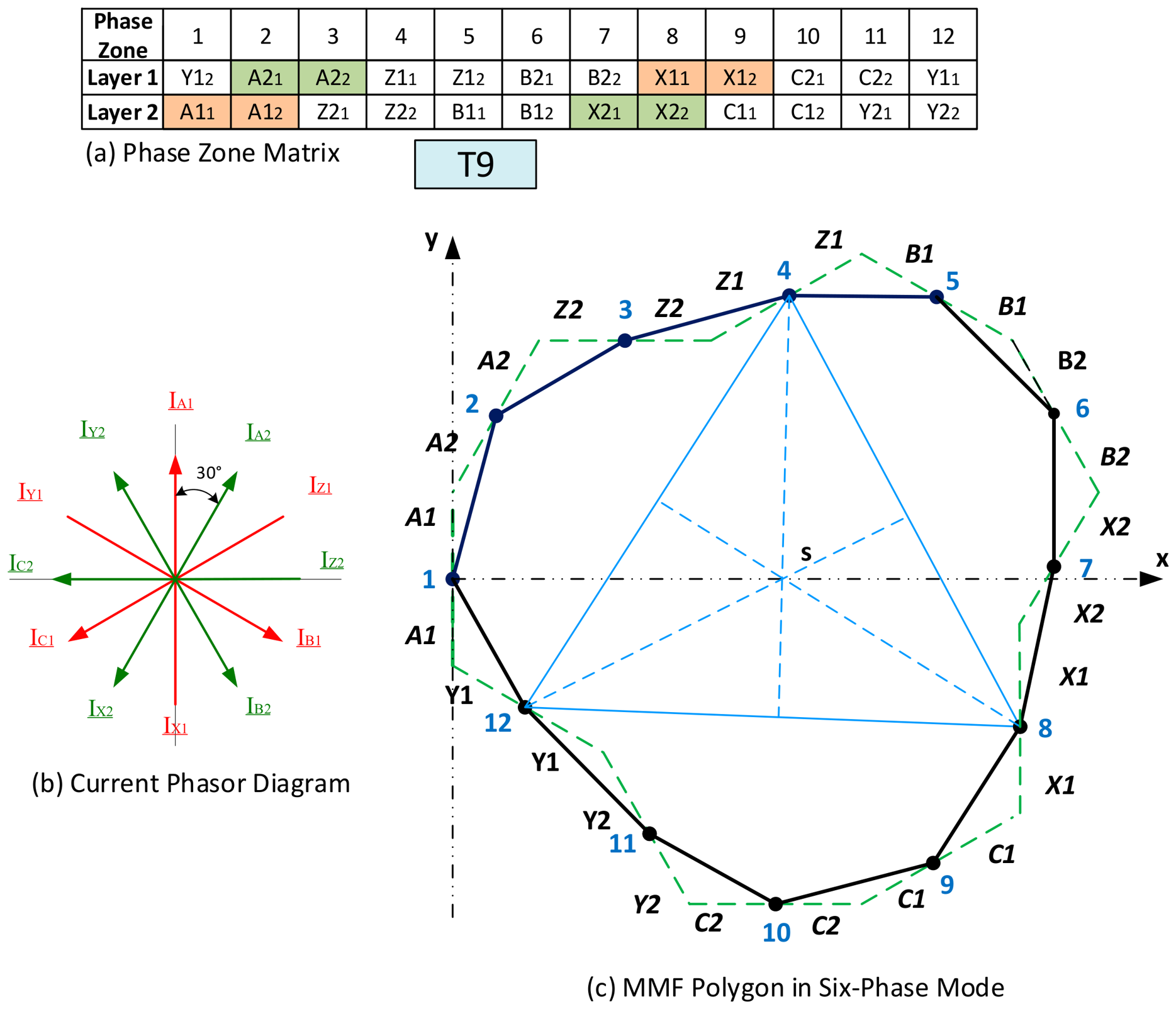
Figure 6 illustrates the phase zone matrix, the current phasor diagram, and the resulting MMF polygon for Model T9. The components of the polygon sides, (indicated by the dashed line in
Figure 6c) are oriented according to the directions of the respective current phasors (
Figure 6b). Each slot is represented on the MMF polygon by two segments of equal length. The conventional unit is defined as the total current of one section:
. In this specific case, the MMF polygon comprises three identical zones (between nodes 12-4, 4-8, and 8-12). The chords connecting these respective nodes form an equilateral triangle. The intersection of the medians of this triangle marks the center of gravity for both the individual triangles and the MMF polygon as a whole [
30].
Scientific Interpretation of the Results
The value obtained for the indicator,
, confirms that the considered winding, under normal six-phase supply conditions, ensures the creation of a rotating magnetic field in the air gap with a very low content of higher spatial harmonics. Using the methodology examined above, calculations were performed for nine distinct six-phase winding scenarios, as indicated in
Table 1. The comprehensive results are synthesized in the final comparison table,
Table 2.
4.2. Application of the Krondl Method to Evaluate Winding Quality Improvement Measures
The primary approach for improving the quality indicator of a winding,
, is to increase the effective number of slots per pole and phase,
, within the limits permitted by manufacturing technology. The accepted number of slots per pole and phase is defined by the machine’s power (the inner diameter of the stator armature and the minimum permitted tooth width), its multi-polarity, and, naturally, the number of machine phases:
As the slot-per-pole-per-phase parameter q increases from 1 to 2 or 3, one or two intermediate nodes, respectively, are placed on each side of the MMF polygon, thereby refining its geometric representation.
The calculation of the radii of inertia and the quality factor is performed following the algorithm outlined in Examples 1 or 3. It should be noted that, for the same phase-belt width , increasing the number of slots per pole per phase (), results in a corresponding change in the slot pitch: . Consequently, the distribution factor of the winding, , is also modified according to the relationship (5).
4.2.1. Numerical Evaluation of the Impact of q on Winding Quality
Based on the proposed methodology, the impact of increasing the slots per pole and phase () was evaluated for the W6F-T2 winding configuration. The results demonstrate a significant reduction in harmonic distortion:
For this configuration, the parameters are:
, the slot pitch angle
, and the distribution factor
. The radius of the fundamental harmonic is calculated as:
The resulting quality indicator is .
- 2.
Scenario with :
If the number of slots per pole and phase is increased to , the quality indicator further improves to:
4.2.2. Conclusion on Winding Distribution
These results confirm a clear reduction in the factor when doubling and, especially, tripling the number of slots per pole and phase. This leads to a considerable improvement in the harmonic content of the magnetic field within the machine’s air gap.
To achieve a targeted reduction in the amplitude of specific harmonics that severely impact the machine’s starting characteristics—namely the 5th and 7th order spatial harmonics—the pitch shortening (chording) procedure is implemented. Among the winding configurations analyzed in this study, four scenarios utilize a shortened pitch: T2, T7, T8, and T9. The effectiveness of this measure specifically for six-phase windings will be analyzed in detail within
Section 5.
4.3. Application of the Krondl Methodology for Assessing Six-Phase Windings Under Faulty Supply Conditions
In the case of six-phase machines, as previously mentioned, significant emphasis is placed on fault tolerance—specifically, the machine’s ability to maintain a rotating magnetic field and generate mechanical torque even when the power supply to one, two, or even three phases is interrupted.
The loss of these capabilities can lead to severe distortion of the magnetic field and an excessive increase in the amplitude of higher harmonics relative to the fundamental component. Consequently, changes in the MMF diagram shape and the winding quality factor () upon phase disconnection serve as key indicators for forecasting the fault tolerance of a machine with a specific winding type.
Experimental data have demonstrated that under single-phase open-circuit conditions, both symmetrical and asymmetrical six-phase machines can operate at nominal load for a limited period [
14]. In the present study, attention is focused on an extreme supply regime—the three-phase mode, occurring when one of the two three-phase winding sets is disconnected.
All nine base models listed in
Table 1 were subjected to this analysis. The computational results are reflected in
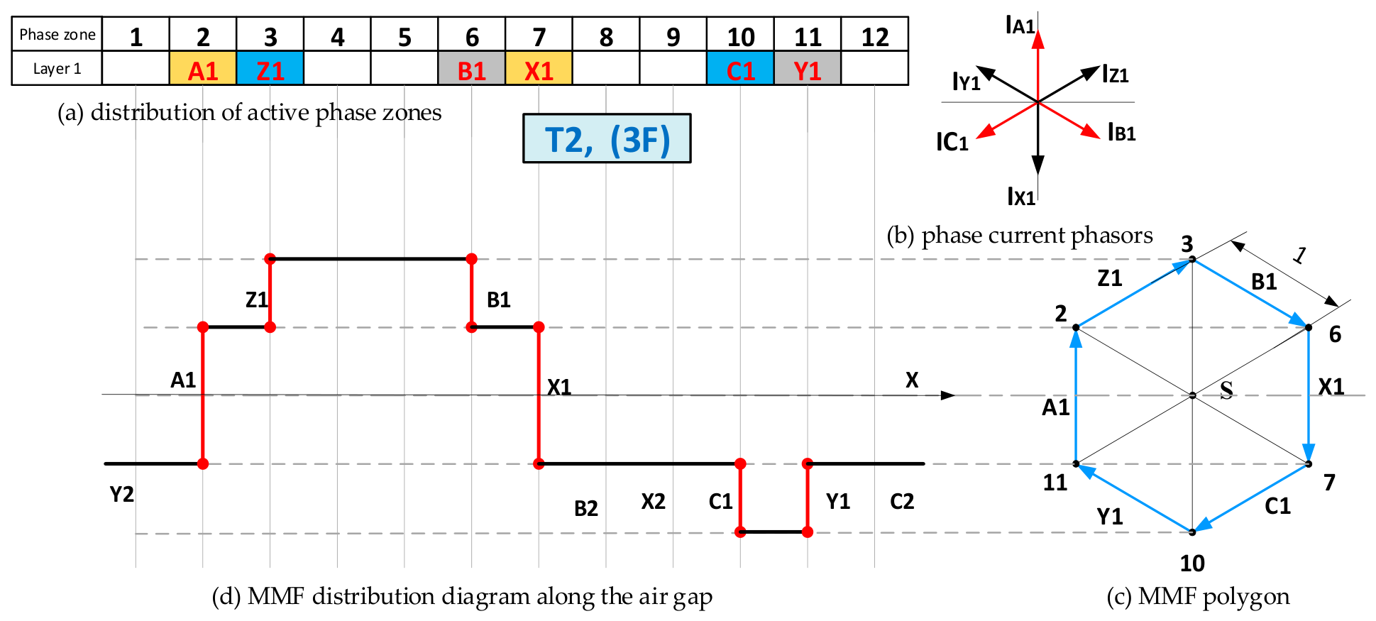
Table 2. Below, as illustrative examples, we present the results for the W6F-T2 (
Figure 7) and W6F-T9 windings (
Figure 8), which exhibit extreme (opposite) fault-tolerance capabilities.
Case Study 4. Operation Under Single Three-Phase Set Supply
Let us consider a six-phase machine with the winding parameters described in Example 1, supplied only through the A1–B1–C1 three-phase set, while phases A2, B2, and C2 remain open-circuited.
Figure 7 presents the resulting MMF polygon and diagram for the considered winding configuration.
It is observed that the MMF polygon remains symmetrical with respect to pole , which confirms that the magnetic field in the air gap contains no even harmonics. However, the asymmetry of the MMF diagram relative to the axis is a clear indicator of the presence of the order subharmonic.
In this specific case (scenario T2), the radius of inertia of the polygon is equal to the radius of any of its 6 nodes (
Figure 7c). Assuming
, we obtain:
This excessively high value of the quality factor confirms a massive presence of parasitic harmonics, which significantly affects the machine’s operating capacity when powered on a single three-phase star.
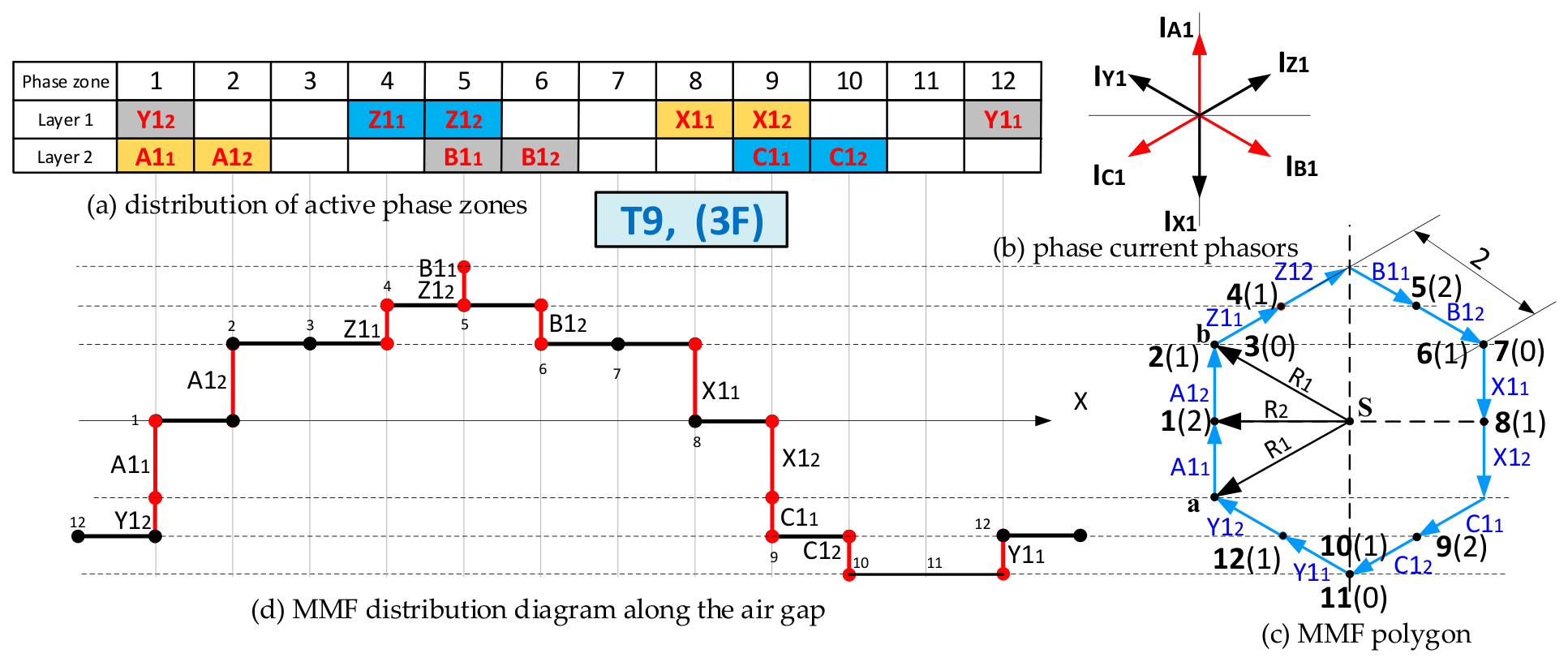
For the T9 topology under 3F (three-phase) operation, the following values are determined based on the characteristic triangle
:
Taking into account the different weights assigned to the polygon nodes (shown in parentheses in the diagram), the mean squared radius of gyration is:
Effective perimeter (
) and fundamental radius (
):
The squared radius of gyration corresponding to the fundamental harmonic is:
Consequently, the quality factor of the T9 winding under three-phase operation is:
This result is consistent with the value reported in
Table 2.
Both the winding quality factor and the machine’s fault tolerance improve considerably when doubling or tripling the number of slots per pole and phase ().
All calculations in the present study were performed using Microsoft Excel 2019. Computer-based approaches to winding analysis are also described in [
28,
33].
Figure 8 presents the resulting MMF polygon and diagram for the W6F-T9 windings configuration, and it is useful for visual comparison between scenarios T2 and T9.
5. Result Analysis and Classification of Six-Phase Windings Recommendations
Table 2 presents the computed values of the Winding Quality Factor for nine base six-phase bipolar induction machine winding models, as listed in
Table 1. The quality factor was calculated for both the nominal regime (
) and for operation with three healthy phases (
). Results are presented for the limiting scenario where
. Additionally, for several promising configurations, variants with
and
were also examined.
Based on the quality factor values obtained across both operating regimes, a rating system for six-phase windings was developed (
Table 2). This classification allows for the formulation of valuable recommendations regarding the prioritization of these windings in practical applications, based on specific performance requirements and fault tolerance (FT) capabilities.
The analysis highlights the following main aspects:
Under nominal operating conditions (six healthy phases), two distinct quality levels for the windings are identified. These are characterized by winding quality factor values of and , corresponding to Ratings 1 and 2, respectively. The differences between these levels are primarily determined by the topological structure of the winding and the distribution of the coil sections within the slots. Under fault operating conditions (three healthy phases), two acceptable performance levels are identified, corresponding to values of and , classified as Ratings 1 and 2. Higher quality factor values indicate a more pronounced distortion of the magnetic field and, consequently, lower fault tolerance. Such topologies are categorized into Levels 3 and 4.
Based on these results, the following conclusions and recommendations can be formulated:
Asymmetrical windings (T1, T3) exhibit superior performance during nominal operation. However, to ensure satisfactory fault tolerance, these structures must be designed with at least two slots per pole and phase ().
Symmetrical windings (T4, T5, T6) show slightly lower efficiency in nominal mode compared to asymmetrical ones. However, even in the critical case where q = 1, they exhibit high fault tolerance. Under three-phase supply conditions, their behavior is comparable to that of a standard three-phase machine.
Type T8 (symmetrical) and T9 (asymmetrical) windings stand out as the most advantageous across both analyzed indicators. These topologies combine the high magnetic field quality characteristic of asymmetrical structures with the superior fault tolerance characteristic of symmetrical windings.
Pitch shortening in six-phase windings is, in certain cases, necessary to ensure the desired phase sequence (e.g., for W6F-T2). However, this measure must be applied with caution, as it can alter the displacement angle between the two three-phase sets and, consequently, influence behavior during fault-mode operation.
6. Experimental Validation and Argumentation
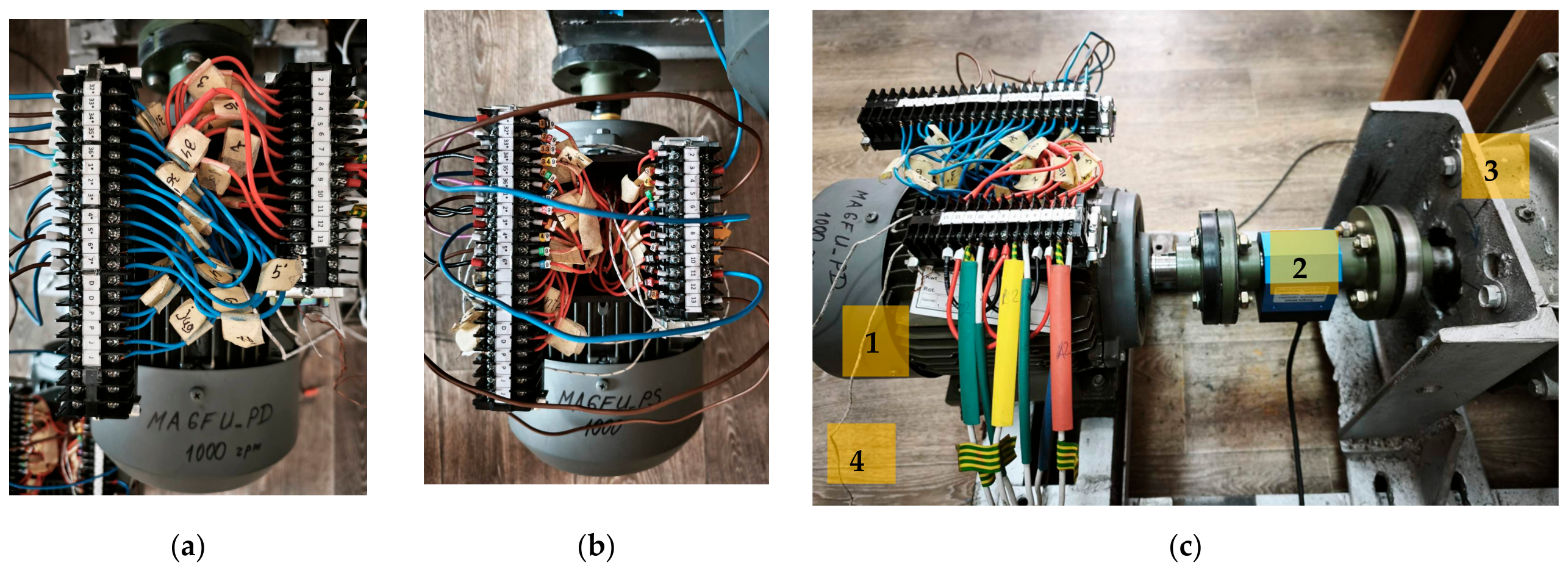
To validate the analytical findings and the proposed winding quality factor, experimental measurements were conducted on a dedicated laboratory test bench. The investigation focuses on two reconfigurable six-phase (
) induction-machine prototypes, specifically designed to evaluate the influence of stator winding topologies on magnetic field quality. Both machines were built using identical stator cores and rotors and are characterized by the following rated and design parameters: rated power: 1.1 kW; rated phase voltage: 220 V; rated torque: 11 N·m; rated speed: 930 rpm; number of poles:
(three pole pairs); number of stator slots:
; and number of rotor bars:
(
Figure 9). The stator winding has a double-layer configuration, with each slot comprising a total of 160 turns, distributed as 80 turns per layer. The coils are wound with round enameled copper wire having a bare-conductor diameter of 0.53 mm and a copper cross-sectional area of 0.221 mm
2. The rated phase current is 1.48 A. The tests were performed at a supply frequency of 50 Hz and a rated phase voltage of 220 V.
The two prototypes, designated MA6F-PD and MA6F-PS, feature double-layer windings and differ exclusively in their coil pitch configurations:
MA6F-PD (Full Pitch): Incorporates a double-layer winding with full (diametrical) pitch (
Figure 9a).
MA6F-PS (Shortened Pitch): Utilizes an identical double-layer topology but with a shortened pitch to investigate the suppression of higher-order harmonics (
Figure 9b).
By routing the phase winding ends to an external terminal block, it was possible to physically reconfigure the connections to model eight of the nine six-phase winding scenarios presented in
Table 1. The comprehensive experimental setup is illustrated in
Figure 9, detailing the prototype configurations and the measurement instrumentation.
The starting torque–speed characteristic directly reflects the presence and relative significance of higher spatial harmonics within the air-gap magnetic field. These harmonics manifest as local torque dips (parasitic torques), a reduction in the starting torque, and a distortion of the acceleration slope [
10,
18]. A detailed analysis of the relationship between the spatial harmonics of the air-gap magnetic field and the shape of the machine torque–speed characteristics is provided in [
16].
The electrical quantities were measured using a Metrel MI 2885 Master Q4 power-quality analyzer compliant with IEC 61000-4-30 Class , providing simultaneous acquisition of four voltage and four current channels with 16-bit A/D conversion at a sampling rate of 7 kS/s for the 50 Hz supply system. The waveforms and phase relationships were additionally verified using a Fluke ScopeMeter 190–204 Series III portable oscilloscope with four isolated channels and a bandwidth of 200 MHz. Shaft torque and rotational speed were measured using a ZHKY2050B non-contact rotary transducer with a 200 N·m full-scale measuring range, a maximum rotational speed of 8000 rpm, and a specified torque accuracy of ±0.1% FS, corresponding to ±0.2 N·m for the sensor used. The transducer was connected to a SISCO-DPM-RTS5D torque–speed–power indicator, which updated the measured quantities at a rate of 25 readings per second.
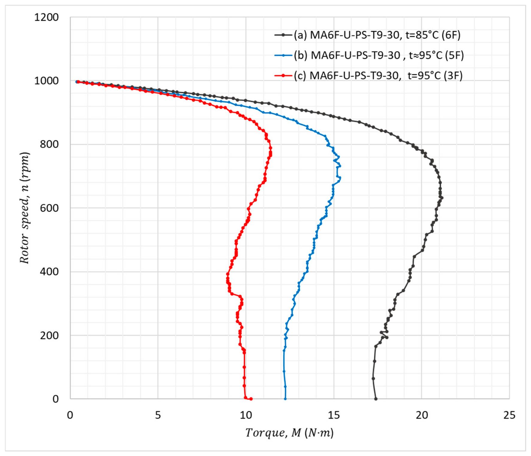
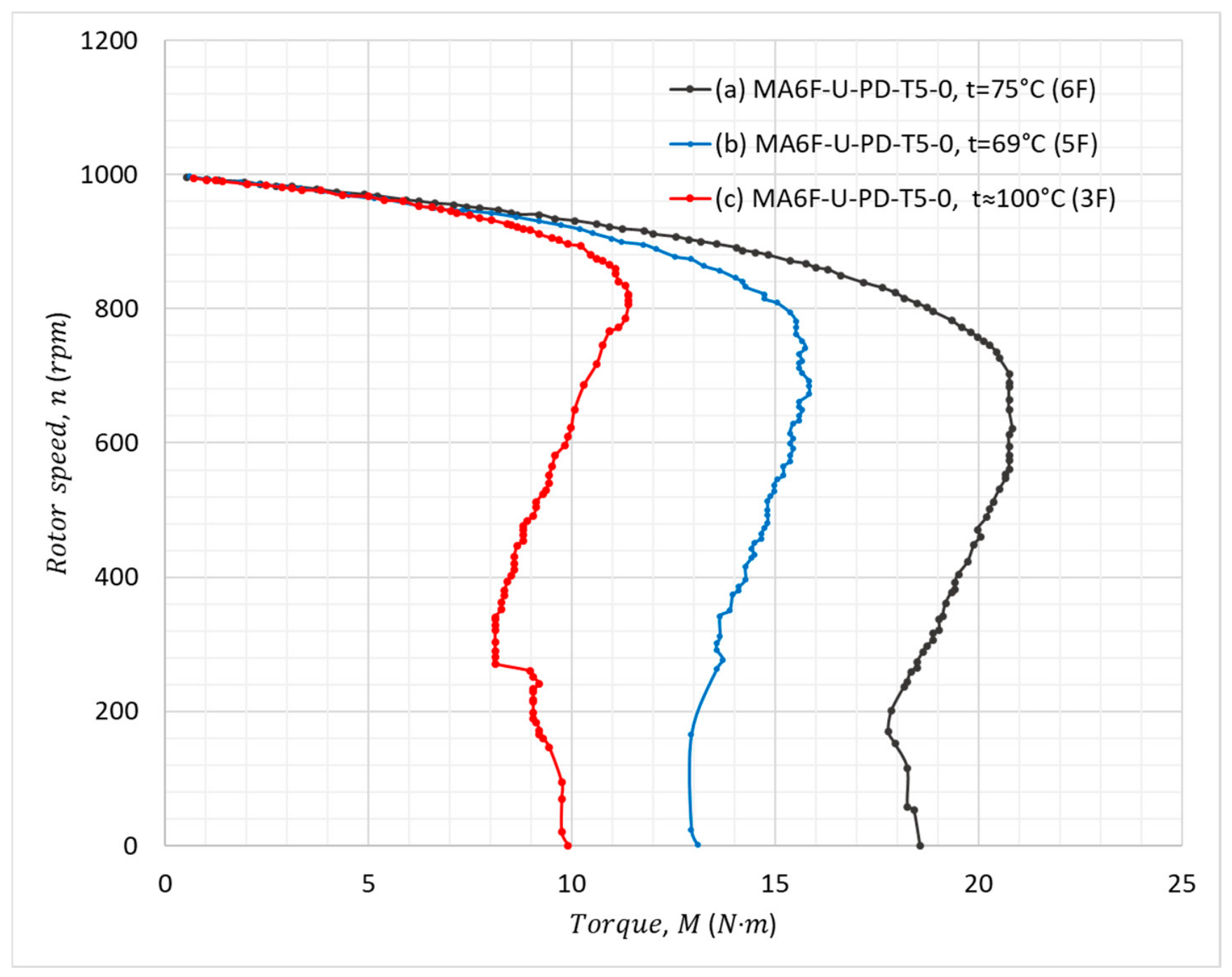
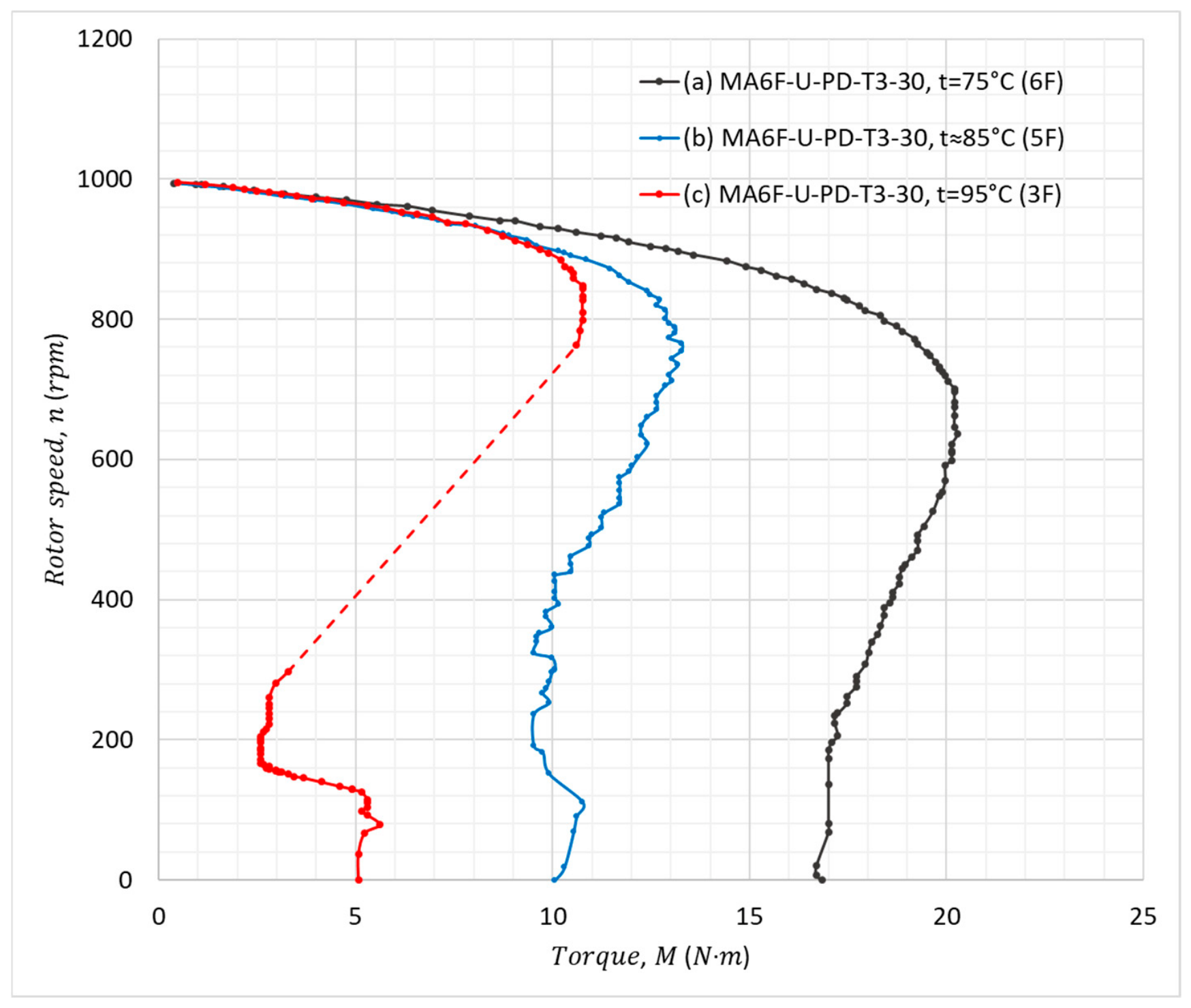
Figure 10,
Figure 11 and
Figure 12 present, as illustrative examples, the starting torque–speed characteristics of three representative winding configurations selected to highlight different values of the winding quality factor under six- and three-phase operation, denoted by
and
, respectively: the T9 shortened-pitch winding (
Figure 10), the T5 diametrical-pitch winding (
Figure 11), and the T3 quasi-single-layer diametrical-pitch winding (
Figure 12). For each configuration, the characteristics are shown for operation with six, five, and three active phases.
The temperatures indicated in the figure legends represent the measured winding temperatures during the corresponding tests. Although these temperature differences affect the stator resistance and may influence the absolute torque values, they do not explain the topology-dependent torque dips or the overall shape of the torque–speed characteristics considered in the comparative analysis.
In both cases, during the nominal operating regime (six healthy phases), high-quality starting characteristics are obtained, evidenced by a high initial torque , a breakdown torque well-positioned on the curve, and the absence of torque dips during acceleration. These results confirm the absence or low level of dominant spatial harmonics of the 5th and 7th orders.
The characteristics corresponding to operating regimes with one affected phase (five healthy phases), represented on the same diagrams, confirm the machine’s ability to start and accelerate under nominal load without significant torque discontinuities. Essential differences appear, however, in the regime with three healthy phases, corresponding to the supply of a single three-phase set. In the case of the prototype equipped with the T9 type winding, the machine develops a mechanical characteristic with satisfactory starting and acceleration capacity, with only a slow torque decrease observed in the slip range , corresponding to the critical slips associated with the 5th and 7th order harmonics.
Conversely, for the T3 scenario (similar to T1 and T7), the starting mechanical characteristic is severely distorted, featuring a reduced initial torque followed by a pronounced torque dip at a speed of approximately 200 rpm. This behavior is a direct consequence of the acute air-gap magnetic field deformation, caused by higher spatial harmonics inherent to concentrated windings with a unitary number of slots per pole and phase (
) [
10,
15,
16,
18,
35].
The obtained experimental results convincingly confirm the conclusions of the theoretical analysis and demonstrate the validity of using the Winding Quality Factor () as a relevant indicator for assessing the performance and fault tolerance of six-phase machines.
7. Conclusions
This paper presented a unified analytical–graphical framework for the evaluation and classification of stator winding topologies in six-phase induction machines, with emphasis on magnetic field quality and fault tolerance. The proposed approach, based on the combined use of magnetomotive force (MMF) distribution analysis and the MMF polygon (Krondl method), enables a consistent and quantitative assessment of the harmonic content in the air-gap magnetic field through the winding quality factor. The results demonstrate that the winding topology has a decisive influence on both the electromagnetic performance and the fault-tolerant capability of six-phase machines. In particular, asymmetrical windings generally provide superior performance under nominal operating conditions due to improved magnetic field quality, whereas symmetrical configurations exhibit enhanced robustness under fault scenarios, especially during operation with a single three-phase set.
It was shown that the harmonic content of the MMF can be significantly reduced by appropriate selection of key design parameters, such as the number of slots per pole and phase, the phase belt width, and the coil pitch. The use of double-layer windings and pitch shortening techniques contributes to improving the winding quality factor by attenuating dominant spatial harmonics. Furthermore, increasing the number of slots per pole and phase leads to a substantial improvement in magnetic field waveform quality. A comprehensive comparative analysis of nine representative winding topologies enabled the establishment of a performance-based classification, highlighting the trade-offs between magnetic field quality and fault tolerance. Among the investigated configurations, the T8 and T9 winding structures were identified as the most advantageous, offering an optimal compromise between high electromagnetic performance and reliable operation under degraded supply conditions.
The experimental results obtained from six-phase induction machine prototypes confirmed the validity of the proposed methodology and demonstrated a strong correlation between the winding quality factor, the harmonic structure of the magnetic field, and the resulting torque–speed characteristics. Overall, the proposed framework provides a practical and efficient tool for the design and selection of stator windings in multiphase machines, without the need for complex numerical simulations. The findings of this study contribute to the advancement of high-reliability electric drive systems and support the broader adoption of six-phase induction machines in applications requiring enhanced fault tolerance and performance.
Author Contributions
Conceptualization, P.T., G.T., I.N. and V.C.; methodology, G.T.; software, A.D., G.T., C.N. and I.N.; validation, P.T., G.T. and I.N.; formal analysis, P.T., V.C. and C.N.; investigation, G.T., I.N. and A.D.; resources, G.T.; data curation, G.T.; writing—original draft preparation, G.T. and A.D.; writing—review and editing, G.T., I.N., A.D. and V.C.; visualization, P.T.; supervision, P.T.; project administration, P.T.; funding acquisition, P.T. and A.D. All authors have read and agreed to the published version of the manuscript.
Funding
This research was funded by the Technical University of Moldova, grant number 020406, “Models, systems and technologies for energy efficiency, decarbonisation and digitization of energy, industry, construction and transport processes” (MoSiTed). Part of this work was supported by a grant of the Ministry of Education and Research, CCCDI—UEFISCDI, project number PN-IV-PCB-RO-MD-2024-0264, within PNCDI IV.
Data Availability Statement
Data are unavailable due to the privacy requirements of the research project. On certain demands, some of the data may be shared depending on the scope.
Acknowledgments
This research was funded by the Technical University of Moldova, grant number 020406, “Models, systems and technologies for energy efficiency, decarbonisation and digitization of energy, industry, construction and transport processes” (MoSiTed). Part of this work was supported by a grant of the Ministry of Education and Research, CCCDI—UEFISCDI, project number PN-IV-PCB-RO-MD-2024-0264, within PNCDI IV.
Conflicts of Interest
The authors declare no conflicts of interest.
References
- Singh, G.K. Multi-phase induction machine drive research—A survey. Electr. Power Syst. Res. 2002, 61, 139–147. [Google Scholar] [CrossRef] [Scilit]
- Barrero, F.; Duran, M.J. Recent advances in the design, modeling, and control of multiphase machines—Part I. IEEE Trans. Ind. Electron. 2016, 63, 449–458. [Google Scholar] [CrossRef] [Scilit]
- Dana TM4. Motor and Inverter Systems. Available online: https://www.danatm4.com/systems.html (accessed on 6 August 2026).
- Frikha, M.A.; Croonen, J.; Deepak, K.; Benômar, Y.; El Baghdadi, M.; Hegazy, O. Multiphase motors and drive systems for electric vehicle powertrains: State of the art analysis and future trends. Energies 2023, 16, 768. [Google Scholar] [CrossRef] [Scilit]
- Koenigsegg Automotive AB. Dark Matter E-Motor Specs. Available online: https://www.koenigsegg.com/dark-matter (accessed on 6 August 2026).
- Sun, Y.; Lin, Y.; Wang, Y.; Nilssen, R.; Shen, J.-X. Theory of symmetric winding distributions and a general method for winding MMF harmonic analysis. IET Electr. Power Appl. 2020, 14, 2587–2597. [Google Scholar] [CrossRef] [Scilit]
- Wu, Z.-Z.; Shen, J.-X. A versatile analytical method of investigating MMF harmonics of armature windings. IEEE Access 2023, 11, 60181–60190. [Google Scholar] [CrossRef] [Scilit]
- Chen, Z.; Xing, N.; Ma, H.; Li, Z.; Li, J.; Fan, C. Armature MMF and electromagnetic performance analysis of dual three-phase 10-pole/24-slot permanent magnet synchronous machine. Arch. Electr. Eng. 2023, 72, 189–210. [Google Scholar] [CrossRef] [Scilit]
- Rudden, I.A.; Li, G.-J.; Kana Padinharu, D.K.; Zhu, Z.Q.; Duke, A.; Clark, R.; Thomas, A. Space harmonic cancellation in a dual three-phase SPM machine with star-delta windings. IEEE Trans. Energy Convers. 2024, 39, 457–468. [Google Scholar] [CrossRef] [Scilit]
- Boldea, I. Induction Machines Handbook: Transients, Control Principles, Design and Testing, 3rd ed.; CRC Press: Boca Raton, FL, USA, 2020; ISBN 9781003033424. [Google Scholar] [CrossRef] [Scilit]
- Levi, E. Multiphase electric machines for variable-speed applications. IEEE Trans. Ind. Electron. 2008, 55, 1893–1909. [Google Scholar] [CrossRef] [Scilit]
- Yepes, A.G.; González-Prieto, I.; Lopez, O.; Duran, M.J.; Doval-Gandoy, J. A comprehensive survey on fault tolerance in multiphase AC drives, Part 2: Phase and switch open-circuit faults. Machines 2022, 10, 221. [Google Scholar] [CrossRef] [Scilit]
- Munim, W.N.W.A.; Duran, M.J.; Che, H.S.; Bermúdez, M.; González-Prieto, I.; Rahim, N.A. A unified analysis of the fault tolerance capability in six-phase induction motor drives. IEEE Trans. Power Electron. 2017, 32, 7824–7836. [Google Scholar] [CrossRef] [Scilit]
- Tertea, G.; Todos, P.; Nuca, I.; Cazac, V. The fault working regimes of the six-phase symmetrically wound asynchronous motor. In Proceedings of the 2023 International Symposium on Fundamentals of Electrical Engineering (ISFEE), Bucharest, Romania, 16–18 November 2023; pp. 1–6. [Google Scholar] [CrossRef] [Scilit]
- Todos, P.; Tertea, G.; Nuca, I. Harmonic analysis of magnetomotive force in the air gap of six-phase asynchronous machines. J. Eng. Sci. 2024, 31, 27–43. [Google Scholar] [CrossRef] [Scilit] [PubMed]
- Tertea, G.; Todos, P.; Nuca, I. Asynchronous torques generated by spatial harmonics of magnetomotive forces. In Proceedings of the 2024 IEEE International Conference and Exposition on Electric and Power Engineering (EPEi), Iasi, Romania, 17–19 October 2024; pp. 636–641. [Google Scholar] [CrossRef] [Scilit]
- Li, X.; Liang, S.; Qi, B.; Zhao, Z.; Ling, Z. Design and Analysis of a Double-Three-Phase Permanent Magnet Fault-Tolerant Machine with Low Short-Circuit Current for Flywheel Energy Storage. Machines 2025, 13, 720. [Google Scholar] [CrossRef] [Scilit]
- Richter, R. Windings of Electrical Machines; Editura Tehnică: Bucharest, Romania, 1958; p. 318. (In Romanian) [Google Scholar]
- Kučera, J.; Hapl, J. Windings of Rotary Electrical Machines; Czechoslovak Academy of Sciences: Prague, Czech Republic, 1963. [Google Scholar]
- Heller, B.; Hamata, V. Harmonic Field Effects in Induction Machines; Elsevier: Amsterdam, The Netherlands, 1977; ISBN 9780444998569. [Google Scholar]
- Vol’dek, A.I.; Popov, V.V. Electrical Machines: AC Machines; Piter: St. Petersburg, Russia, 2008; ISBN 978-5-469-01381-5. (In Russian) [Google Scholar]
- Kostenko, M.P.; Petrovski, L.M. Electrical Machines: AC Machines; Energia: Moscow, Russia, 1973. (In Russian) [Google Scholar]
- Kopylov, I.P.; Klokov, B.K.; Morozkin, V.P.; Tokarev, B.F. Design of Electrical Machines, 4th ed.; Yurayt: Moscow, Russia, 2011. (In Russian) [Google Scholar]
- Belikova, L.I.; Petrushin, V.S.; Chaikovskii, V.P.; Yakimets, A.M. Six-phase windings of induction motor stators. Elektr. Comput. Syst. 2018, 29, 40–47. (In Russian) [Google Scholar]
- Kutsyk, A.; Korkosz, M.; Bogusz, P.; Semeniuk, M.; Lozynskyy, A. An analysis of asymmetrical and open-phase modes in a symmetrical two-channel induction machine with consideration of spatial harmonics. Energies 2024, 17, 870. [Google Scholar] [CrossRef] [Scilit]
- Abdel-Khalik, A.S.; Abdel-Majeed, M.S.; Ahmed, S. Effect of winding configuration on six-phase induction machine parameters and performance. IEEE Access 2020, 8, 223009–223020. [Google Scholar] [CrossRef] [Scilit]
- Kalas, B.A.; Refaat, A.; Fawzi, M.; Abdel-Khalik, A.S. A comparative study of three winding configurations for six-phase induction motors. In Engineering Solutions Toward Sustainable Development; Negm, A.M., Rizk, R.Y., Abdel-Kader, R.F., Ahmed, A., Eds.; Springer: Cham, Switzerland, 2024; pp. 669–686. [Google Scholar] [CrossRef] [Scilit]
- Mădescu, G.; Berwanger, E.; Biriescu, M.; Mot, M.; Greconici, M. Very Fast Prediction of MMF Harmonics Content in Multiphase Electrical Machines. In Proceedings of the IEEE EUROCON 2019—18th International Conference on Smart Technologies, Novi Sad, Serbia, 1–4 July 2019; pp. 1–6. [Google Scholar] [CrossRef] [Scilit]
- Smirnov, A.Y. Matrix synthesis and analysis of MMF polygons of three-phase windings of alternating current machines. Elektrichestvo 2009, 5, 42–45. [Google Scholar]
- Todos, P.; Tertea, G.; Nuca, I. Analysis of stator winding topologies of six-phase AC machines using the winding quality factor. In Proceedings of the 2025 International Conference on Electromechanical and Energy Systems (SIELMEN), Iasi, Romania, 15–17 October 2025; pp. 414–419. [Google Scholar] [CrossRef] [Scilit]
- Degtev, V.G.; Lavruk, I.S. Multiphase winding homologous series synthesis and harmonic analysis. Electr. Eng. Electromech. 2014, 1, 25–30. (In Russian) [Google Scholar] [CrossRef] [Scilit]
- Degtev, V.G.; Lavruk, I.S. The system of symmetrical three-phase windings of electrical machines. Elektrichestvo 2015, 3, 41–48. [Google Scholar]
- Bogatyrev, N.; Kramer, A.; Bogdan, V.; Semernin, D. Matrix comparison method of stator windings of induction generators by harmonic composition of magnetomotive force. In Proceedings of the 19th International Scientific Conference Engineering for Rural Development, Jelgava, Latvia, 20–22 May 2020; pp. 851–856. [Google Scholar]
- Todos, P.; Nuca, I.; Tertea, G.; Cazac, V. Identification of parameters and power losses of six-phase asynchronous machines by induction regenerative method. In Proceedings of the 10th International Conference on Modern Power Systems (MPS), Cluj-Napoca, Romania, 21–23 June 2023; pp. 1–6. [Google Scholar] [CrossRef] [Scilit]
- Verbytskyi, I.; Lukianov, M.; Bondarenko, Y. Principle of torque formation with reduced pulsation in switched reluctance motor with U-shaped poles. Bull. Natl. Tech. Univ. KhPI Ser. New Solut. Mod. Technol. 2021, 3, 3–10. (In Ukrainian) [Google Scholar] [CrossRef] [Scilit]
Figure 1.
Base model for a single-layer three-phase winding with m = 3, p = 1, Z = 12: (a) Slot distribution. (b) Phase belts. (c) Developed winding layout for p-pole configuration. (d) Phase coil group arrangement for 2p–pole configuration. Brown, dark grey, and blue identify phases A–X, B–Y, and C–Z, respectively; the same colour coding applies to the slot numbers, phase labels, winding lines, and arrows. Numbers 1–12 identify the stator slots. Letters A, B, and C denote the outgoing coil sides, while X, Y, and Z denote the corresponding return sides. The arrows indicate the directions of the currents, and the grey-shaded regions marked N and S indicate the magnetic pole regions.
Figure 1.
Base model for a single-layer three-phase winding with m = 3, p = 1, Z = 12: (a) Slot distribution. (b) Phase belts. (c) Developed winding layout for p-pole configuration. (d) Phase coil group arrangement for 2p–pole configuration. Brown, dark grey, and blue identify phases A–X, B–Y, and C–Z, respectively; the same colour coding applies to the slot numbers, phase labels, winding lines, and arrows. Numbers 1–12 identify the stator slots. Letters A, B, and C denote the outgoing coil sides, while X, Y, and Z denote the corresponding return sides. The arrows indicate the directions of the currents, and the grey-shaded regions marked N and S indicate the magnetic pole regions.
Figure 2.
Double-layer three-phase full-pitch windings: chain winding configuration with phase winding coils distributed over poles. Brown, dark grey, and blue identify phases A–X, B–Y, and C–Z, respectively; the same colour coding applies to the slot numbers, phase labels, winding lines, and arrows. Numbers 1–12 identify the stator slots. The letters A, B and C designate the active leading sides of the coil, while X, Y and Z designate the corresponding return sides. The arrows indicate the directions of the currents, and the grey-shaded regions marked N and S indicate the magnetic pole regions. Solid and dashed lines represent the upper and lower winding layers, respectively.
Figure 2.
Double-layer three-phase full-pitch windings: chain winding configuration with phase winding coils distributed over poles. Brown, dark grey, and blue identify phases A–X, B–Y, and C–Z, respectively; the same colour coding applies to the slot numbers, phase labels, winding lines, and arrows. Numbers 1–12 identify the stator slots. The letters A, B and C designate the active leading sides of the coil, while X, Y and Z designate the corresponding return sides. The arrows indicate the directions of the currents, and the grey-shaded regions marked N and S indicate the magnetic pole regions. Solid and dashed lines represent the upper and lower winding layers, respectively.
Figure 3.
Single-layer six-phase winding: (a) slot sequence number; (b) phase belt matrix; (c) developed winding layout. Brown and light brown identify phases A1–X1 and A2–X2; grey and light grey identify B1–Y1 and B2–Y2; blue and light blue identify C1–Z1 and C2–Z2, respectively. The same colours are used for the phase labels, winding lines, and current-direction arrows. The numbers 1 and 2 in the phase designation distinguish the two sets of three-phase windings. Numbers 1–12 identify the stator slots, while the grey-shaded regions marked and indicate the magnetic pole regions. For simplicity, only 12 stator slots, corresponding to one pole pair, are shown; the winding pattern repeats beyond the illustrated section.
Figure 3.
Single-layer six-phase winding: (a) slot sequence number; (b) phase belt matrix; (c) developed winding layout. Brown and light brown identify phases A1–X1 and A2–X2; grey and light grey identify B1–Y1 and B2–Y2; blue and light blue identify C1–Z1 and C2–Z2, respectively. The same colours are used for the phase labels, winding lines, and current-direction arrows. The numbers 1 and 2 in the phase designation distinguish the two sets of three-phase windings. Numbers 1–12 identify the stator slots, while the grey-shaded regions marked and indicate the magnetic pole regions. For simplicity, only 12 stator slots, corresponding to one pole pair, are shown; the winding pattern repeats beyond the illustrated section.
Figure 4.
Construction of the MMF polygon and diagram for the six-phase single-layer winding (Model T2): (a) phase zone distribution; (b) phase current phasor diagram; (c) MMF polygon.
Figure 4.
Construction of the MMF polygon and diagram for the six-phase single-layer winding (Model T2): (a) phase zone distribution; (b) phase current phasor diagram; (c) MMF polygon.
Figure 5.
Construction of the MMF diagram for the double-layer shortened-pitch winding (Model T7). The time axis (TA) is aligned with the magnetic axis of phase A1, which is traversed at the given moment by the peak (maximal) current ().
Figure 5.
Construction of the MMF diagram for the double-layer shortened-pitch winding (Model T7). The time axis (TA) is aligned with the magnetic axis of phase A1, which is traversed at the given moment by the peak (maximal) current ().
Figure 6.
Construction of the MMF diagram for the T9-type double-layer winding; (a) phase zone matrix; (b) current phasor diagram; (c) MMF polygon in six-phase mode.
Figure 6.
Construction of the MMF diagram for the T9-type double-layer winding; (a) phase zone matrix; (b) current phasor diagram; (c) MMF polygon in six-phase mode.
Figure 7.
MMF diagram during motor operation (Scenario: T2) with three healthy phases: (a) distribution of active phase zones; (b) phase current phasors; (c) MMF polygon; (d) MMF distribution diagram along the air gap.
Figure 7.
MMF diagram during motor operation (Scenario: T2) with three healthy phases: (a) distribution of active phase zones; (b) phase current phasors; (c) MMF polygon; (d) MMF distribution diagram along the air gap.
Figure 8.
MMF diagram during motor operation (Scenario: T9) with three healthy phases: (a) distribution of active phase zones; (b) phase current phasors; (c) MMF polygon (the relative mass of each node is indicated in parentheses); (d) MMF distribution diagram along the air gap.
Figure 8.
MMF diagram during motor operation (Scenario: T9) with three healthy phases: (a) distribution of active phase zones; (b) phase current phasors; (c) MMF polygon (the relative mass of each node is indicated in parentheses); (d) MMF distribution diagram along the air gap.
Figure 9.
Experimental test bench for six-phase induction machine analysis: (a) general view of the MA6F-PD prototype with reconfigurable terminal block; (b) general view of the MA6F-PS prototype; (c) overall view of the test stand featuring: 1—the tested machine (MA6F), 2—ZHKY2050B rotary torque transducer connected to the SISCO-DPM-RTS5D torque–speed–power indicator, 3—DC generator loading system, 4—integrated temperature sensors for thermal monitoring.
Figure 9.
Experimental test bench for six-phase induction machine analysis: (a) general view of the MA6F-PD prototype with reconfigurable terminal block; (b) general view of the MA6F-PS prototype; (c) overall view of the test stand featuring: 1—the tested machine (MA6F), 2—ZHKY2050B rotary torque transducer connected to the SISCO-DPM-RTS5D torque–speed–power indicator, 3—DC generator loading system, 4—integrated temperature sensors for thermal monitoring.
Figure 10.
MA6F motor: T9 shortened-pitch winding (, ). Starting torque–speed characteristics under operating regimes with 6, 5, and 3 healthy phases, respectively.
Figure 10.
MA6F motor: T9 shortened-pitch winding (, ). Starting torque–speed characteristics under operating regimes with 6, 5, and 3 healthy phases, respectively.
Figure 11.
MA6F motor: T5 with diametrical pitch (, ). Starting torque–speed characteristics under operating regimes with 6, 5, and 3 healthy phases, respectively.
Figure 11.
MA6F motor: T5 with diametrical pitch (, ). Starting torque–speed characteristics under operating regimes with 6, 5, and 3 healthy phases, respectively.
Figure 12.
MA6F motor: T3 quasi-single-layer winding with diametrical pitch (, ). Starting torque–speed characteristics under operating regimes with 6, 5, and 3 healthy phases, respectively.
Figure 12.
MA6F motor: T3 quasi-single-layer winding with diametrical pitch (, ). Starting torque–speed characteristics under operating regimes with 6, 5, and 3 healthy phases, respectively.
Table 1.
Topological models of six-phase windings. Phase belt and coil distribution matrix.
Table 1.
Topological models of six-phase windings. Phase belt and coil distribution matrix.
| Layer No. | Phase Belt Distribution |
|---|
| 1 | 2 | 3 | 4 | 5 | 6 | 7 | 8 | 9 | 10 | 11 | 12 |
|---|
| * T0: W3F, SL, DP, SIM, 2p = 2 |
| 1 (Single layer (SL)) | Y | A | Z | B | X | C | Y |
| T1: W6F, SL, DP, ASYM, 2p = 2, |
| 1 (Single layer (SL)) | Y2 | A1 | A2 | Z1 | Z2 | B1 | B2 | X1 | X2 | C1 | C2 | Y1 |
| T2: W6F, SL, PSh, SYM, 2p = 2, |
| 1 (Single layer (SL)) | Y2 | A1 | Z1 | A2 | Z2 | B1 | X1 | B2 | X2 | C1 | Y1 | C2 |
| T3: W6F, DL, DP, ASYM, 2p = 2, PZW = 30°, |
| 1 (Upper layer) | Y22 | A11 | A21 | Z11 | Z21 | B11 | B21 | X12 | X22 | C12 | C22 | Y12 |
| 2 (Lower layer) | Y21 | A12 | A22 | Z12 | Z22 | B12 | B22 | X11 | X21 | C11 | C21 | Y11 |
| T4: W6F, DL, DP, SYM, 2p = 2, PZW = 60°, |
| 1 (Upper layer) | C22 | A11 | A12 | A21 | A22 | B11 | B12 | B21 | B22 | C11 | C12 | C21 |
| 2 (Lower layer) | Y12 | Y21 | Y22 | Z11 | Z12 | Z21 | Z22 | X11 | X12 | X21 | X22 | Y11 |
| T5: W6F, DL, DP, SYM, QSL, DTP, 2p = 2, PZW = 60°, |
| 1 (Upper layer) | Y22 | A11 | A12 | Z11 | Z12 | B11 | B12 | X21 | X22 | C11 | C12 | Y21 |
| 2 (Lower layer) | Y12 | A21 | A22 | Z21 | Z22 | B21 | B22 | X11 | X12 | C21 | C22 | Y11 |
| T6: W6F, DL, DP, SYM, Z/Z, 2p = 2, PZW = 30 + 30°, |
| 1 (Upper layer) | Y22 | A11 | Z12 | A21 | Z22 | B11 | X12 | B21 | X22 | C11 | Y12 | C21 |
| 2 (Lower layer) | A12 | Y21 | A22 | Z11 | B12 | Z21 | B22 | X11 | C12 | X21 | C22 | Y11 |
| T7: W6F, DL, PSh, QSL, SYM, 2p = 2, PZW = 30°, |
| 1 (Upper layer) | Y12 | A11 | Y22 | A21 | Z12 | B11 | Z22 | B21 | X12 | C11 | X22 | C21 |
| 2 (Lower layer) | Y21 | A12 | Z12 | A22 | Z21 | B12 | X11 | B22 | X21 | C12 | Y11 | C22 |
| T8: W6F, DL PSh, Z/Z, SYM, 2p = 2, PZW = 30°, = 0° |
| 1 (Upper layer) | Y22 | A11 | A21 | Z11 | Z21 | B11 | B21 | X12 | X22 | C12 | C22 | Y12 |
| 2 (Lower layer) | A12 | A22 | Z12 | Z22 | B12 | B22 | X11 | X21 | C11 | C21 | Y11 | Y21 |
| T9: W6, DL, PSh, ASYM, 2p = 2, PZW = 60°, |
| 1 (Upper layer) | Y12 | A21 | A22 | Z11 | Z12 | B21 | B22 | X11 | X12 | C21 | C22 | Y11 |
| 2 (Lower layer) | A11 | A12 | Z21 | Z22 | B11 | B12 | X21 | X22 | C11 | C12 | Y21 | Y22 |
Table 2.
Winding rating for six-phase machines based on quality factor (QF) and fault tolerance (FT) criteria.
Table 2.
Winding rating for six-phase machines based on quality factor (QF) and fault tolerance (FT) criteria.
| Type | W3F-T0 | W6F-T1 | W6F-T2 | W6F-T3 | W6F-T4 | W6F-T5 | W6F-T6 | W6F-T7 | W6F-T8 | W6F-T9 |
|---|
| – | 30° | 60° | 30° | 60° | 0° | 60° | 60° | 0° | 30° |
|---|
| Calculated Parameters: Six-Phase Operating Regime (Nominal) |
| 2 | 1 | 1 | 1 | 2 | 2 | 2 | 2 | 2 | 2 |
| 1 | 1 | 5/6 | 1 | 1 | 1 | 1 | 5/6 | 5/6 | 5/6 |
| – | 1 | 0.966 | 1 | 0.966 | 0.966 | 0.966 | 0.933 | 0.933 | 0.915 |
| – | 3.732 | 3.5 | 3.732 | 14 | 14 | 14 | 13.0 | 13.92 | 12.254 |
| – | 3.648 | 3.403 | 3.648 | 13.61 | 13.61 | 13.61 | 12.70 | 13.61 | 12.18 |
| – | 2.32 | 2.84 | 2.32 | 2.87 | 2.87 | 2.87 | 2.36 | 2.32 | 0.6 |
| Rating | 0 | 1 | 2 | 1 | 2 | 2 | 2 | 1 | 1 | 1 |
| Calculated Parameters: Three-Phase Operating Regime (Fault Mode) |
| 3.5 | 1 | 1 | 1 | 3.5 | 3.5 | 3.5 | 3.75 | 3.5 | 3.25 |
| 3.403 | 0.912 | 0.8508 | 0.912 | 3.403 | 3.403 | 3.403 | 3.403 | 3.403 | 3.175 |
| 2.85 | 9.65 | 17.54 | 9.65 | 2.84 | 2.84 | 2.84 | 10.3 | 2.85 | 2.36 |
| Rating | 2 | 3 | 4 | 3 | 2 | 2 | 2 | 3 | 2 | 1 |
| Rating: 6 Phase/3 Phase Performance |
| Rating | 0/2 | 1/3 | 2/4 | 1/3 | 2/2 | 2/2 | 2/2 | 1/3 | 1/2 | 1/1 |
| Disclaimer/Publisher’s Note: The statements, opinions and data contained in all publications are solely those of the individual author(s) and contributor(s) and not of MDPI and/or the editor(s). MDPI and/or the editor(s) disclaim responsibility for any injury to people or property resulting from any ideas, methods, instructions or products referred to in the content. |





 ,
,