1. Introduction
With the expansion of ultra-high-voltage direct-current transmission projects and the increasing demand for intelligent operation and maintenance of converter stations, state perception, defect identification, and fine-grained inspection of high-voltage equipment in converter valve halls have become important for ensuring the safe operation of DC transmission systems. A converter valve hall contains valve towers, wall-side bushings, connecting busbars, support frames, shielding structures, and other equipment. The spatial environment is highly enclosed, vertically extensive, densely metallic, corridor-like, and locally occluded. Conventional manual inspection usually requires outage or strict safety isolation, resulting in low efficiency, high personnel risk, and limited inspection frequency. UAVs have attracted extensive attention in transmission-line, substation, and power-facility inspection because of their flexible deployment, diversified viewpoints, ability to approach complex structures, and non-contact inspection capability [
1,
2,
3,
4,
5]. However, unlike outdoor transmission-line inspection, converter valve halls are typical indoor high-voltage equipment spaces where GNSS signals are unavailable and electromagnetic and metallic reflection conditions are more complex. Continuous, accurate, and robust self-pose information is therefore a prerequisite for autonomous UAV inspection.
Existing studies on UAV-based power inspection mainly focus on inspection-platform design, visual detection, LiDAR point-cloud acquisition, path planning, and target tracking. For example, Mendu and Mbuli [
1] systematically reviewed the application of UAVs in power-line inspection and pointed out that multi-source perception and autonomous inspection are important future directions. Guan et al. [
2] applied UAV-LiDAR to intelligent power-facility inspection and improved the acquisition of spatial information for lines and equipment. Li et al. [
3] designed a UAV autonomous inspection system for high-voltage power-transmission lines, and Tsellou et al. [
4] developed an intelligent UAV system for power-line monitoring. Other studies further improved autonomous UAV operation from the perspectives of power-line detection, tracking, and visual-assisted inspection [
5]. These studies demonstrate that UAVs have a sound application basis in power inspection. Nevertheless, most existing work targets outdoor lines or relatively open scenarios, where localization usually relies on GNSS, visual assistance, or relatively simple environmental constraints. Stable UAV localization in converter valve halls, which are GNSS-denied, equipment-dense, and metallically complex indoor high-voltage scenarios, remains insufficiently investigated.
For UAV localization in GNSS-limited or GNSS-denied environments, visual sensors, LiDAR, UWB, total stations, inertial measurement units, and their combinations have been investigated as alternative or complementary localization sources. Benjumea et al. [
6] developed a lightweight UAV localization system for inspection tasks, showing the importance of multi-sensor localization when stable GNSS is unavailable. UWB has been widely used in indoor mobile-robot and UAV localization because of its large pulse bandwidth, high ranging accuracy, low power consumption, and suitability for real-time indoor localization [
7,
8,
9,
10]. Yang et al. [
7] verified the feasibility of UWB-based localization for small UAVs in extremely confined spaces. Al-Okby et al. [
8] reviewed UWB-based real-time indoor positioning systems and indicated the strong potential of UWB in mobile-object tracking and indoor localization. Zou et al. [
9] further coupled UWB and IMU measurements to reduce the influence of ranging noise and NLOS errors. However, UWB ranging is highly sensitive to propagation-path quality. In environments with dense metallic equipment, wall occlusion, and strong multipath reflection, NLOS propagation introduces large positive biases, causing localization jumps or systematic offsets. Direct reliance on UWB localization is therefore unreliable in converter valve halls.
LiDAR is an important sensor for indoor robot and UAV autonomous localization because it does not depend on external infrastructure, actively acquires environmental geometric information, and adapts well to low-illumination scenes. In recent years, LiDAR SLAM and tightly coupled LiDAR–IMU methods have developed rapidly. FAST-LIO2 [
11] realizes high-frequency, low-drift LiDAR-inertial odometry through tightly coupled filtering and an efficient mapping structure [
12]. Reviews on multi-sensor SLAM also show that complementary fusion among LiDAR, IMU, and camera sensors can improve localization and mapping robustness in complex environments [
13,
14,
15]. Nevertheless, LiDAR odometry fundamentally depends on adjacent-frame point-cloud matching and local geometric constraints. In converter valve halls, valve-tower arrays, parallel support structures, and narrow corridors can form repetitive geometric features. Some local regions may suffer from point-cloud degeneration or insufficient constraints. When a UAV flies over a long distance along the corridors between valve towers, LiDAR-only localization gradually accumulates drift. Without global constraints or effective loop closure, subsequent task-point arrival, path tracking, and safety-distance judgment can all be affected.
LiDAR–UWB fusion therefore provides a feasible solution for UAV localization in converter valve halls. LiDAR provides continuous and smooth local motion constraints and perceives the internal geometry of the valve hall, whereas UWB provides global distance constraints from fixed anchors and can suppress the long-distance accumulated drift of LiDAR. Recent studies have investigated fusion localization among UWB, LiDAR, IMU, and vision. Xin et al. [
16] proposed a ranging-LiDAR-inertial tightly coupled localization and mapping framework and verified the constraining effect of ranging information on LiDAR-inertial systems. Kuang et al. [
17] proposed a LiDAR/IMU/UWB factor-graph fusion method to improve multi-sensor localization robustness. Chen et al. [
18] used LiDAR point-cloud maps to identify UWB NLOS measurements and constructed an improved UWB/LiDAR-SLAM tightly coupled localization system. Other studies improved localization accuracy in complex environments from visual/UWB and 2D LiDAR/UWB fusion perspectives [
19,
20]. These studies confirm the effectiveness of fusing UWB with LiDAR or other odometry information and provide a methodological basis for this paper.
Despite these advances, directly applying existing multi-source fusion localization methods to UAV inspection in converter valve halls still has limitations. First, existing studies mainly target underground parking lots, forests, mobile robots, or ordinary indoor spaces and seldom consider the spatial occlusion jointly caused by suspended valve towers, grouped wall-side bushings, connecting busbars, and metallic support structures in converter valve halls. Second, many methods identify UWB NLOS propagation using ranging residuals, channel characteristics, or classification models [
21,
22,
23,
24]. In UAV inspection scenarios, however, abnormal UWB ranging is strongly related to the valve-hall geometry, and purely statistical ranging indicators may be delayed. Third, most fusion methods evaluate performance mainly using localization RMSE, with insufficient attention to how localization errors affect task-point arrival, path tracking, and safety-distance judgment. For UAV inspection in converter valve halls, a localization method should not only produce small errors but also support stable arrival at key observation positions and avoid safety-distance misjudgment caused by localization jumps or accumulated drift.
Compared with UWB-only localization, LiDAR/IMU odometry or SLAM, loose LiDAR-UWB fusion, and conventional tight LiDAR-UWB fusion, the proposed method differs mainly in three aspects: it uses valve-hall obstacle geometry to evaluate UWB ranging credibility before optimization, converts the continuous NLOS risk into adaptive ranging variance, and evaluates localization results together with task-arrival, tracking, and safety-distance assessment. This clarification highlights that the contribution is not simply the use of two sensors but the geometry-aware weighting of UWB measurements in a converter valve-hall inspection scenario.
To address these issues, this paper proposes an NLOS-aware LiDAR-UWB fusion localization method for UAV inspection in converter valve halls. The method is intended as a localization-layer solution for GNSS-denied and metallic indoor inspection scenarios. It does not assume that complete UAV deployment in an energized converter valve hall has already been validated. Instead, it focuses on suppressing LiDAR drift and UWB NLOS bias through geometry-aware weighting, and the conclusions are restricted to simulation and randomized robustness validation.
The main contributions of this paper are summarized as follows:
A LiDAR-UWB fusion localization problem model for UAV inspection in converter valve halls is established. The model considers suspended valve towers, grouped wall-side bushings, internal UWB anchors, inspection corridors, and the interaction among sensor observations, task points, and safety-distance evaluation.
A geometry-assisted UWB NLOS risk assessment and adaptive weighting method is proposed. Unlike a deterministic NLOS label, the proposed risk factor continuously describes the proximity between the UAV-anchor link and valve-hall obstacles and converts it into an equivalent UWB ranging variance for tight fusion.
An NLOS-aware tightly coupled LiDAR-UWB optimization framework is established. LiDAR motion residuals, UWB ranging residuals, adaptive ranging weights, and the Huber robust kernel are integrated so that reliable UWB measurements correct LiDAR drift while risky measurements have limited influence.
An inspection-oriented validation framework is constructed. In addition to RMSE, P95 error, and maximum error, task-arrival error, tracking error, true-estimated safety-distance error, false-safe cases, false-alarm cases, and Monte Carlo robustness tests are introduced to evaluate the practical influence of localization errors.
2. Modeling of the UAV Inspection System in Converter Valve Halls
Converter valve halls are core equipment spaces in ultra-high-voltage DC transmission projects. They commonly contain valve towers, valve-side bushings, support frames, shielding structures, and maintenance corridors. Compared with ordinary indoor environments, converter valve halls are enclosed, equipment-dense, metallic, corridor-shaped, GNSS-denied, and electromagnetically complex. During autonomous inspection in such environments, a UAV must not only reach specified equipment or observation positions along a predefined path but also continuously obtain reliable pose information to support trajectory tracking, task-point arrival, view-angle maintenance, and safety-distance judgment.
This paper focuses on LiDAR–UWB fusion localization during UAV inspection in converter valve halls. The system mainly consists of a UAV platform, an onboard LiDAR, a UWB tag, fixed UWB anchors, and the three-dimensional valve-hall environment. LiDAR is mainly used to acquire local environmental geometry and provide continuous relative-motion estimation. UWB provides global position correction through ranging constraints between the UAV tag and fixed anchors. The two sensors are strongly complementary. LiDAR offers good short-term continuity but is prone to accumulated drift during long-distance flight, repetitive structures, and geometrically degenerate areas. UWB provides global distance constraints but is vulnerable to NLOS ranging bias under metallic occlusion and multipath reflection in converter valve halls. Therefore, sensor observation models and disturbance characteristics suitable for converter valve halls are established as the basis for the proposed fusion localization method.
2.1. Valve-Hall Scene and Inspection-Task Definition
Let the converter valve hall be a bounded three-dimensional space. Its spatial region is denoted as follows:
where
denotes the three-dimensional valve-hall space,
is the position vector of a spatial point, and
,
and
denote the dimensions of the valve hall along the three coordinate axes, respectively. In the simulation, the valve-hall space is configured according to a typical converter valve-hall structure to represent the constrained inspection environment jointly formed by valve-tower arrays and valve-side bushings.
The main obstacles inside the converter valve hall include valve towers, bushings, support structures, and other metallic equipment. For unified description, the obstacle set is defined as follows:
where
is the set of valve towers,
is the set of valve-side bushings or column-like equipment, and
is the set of support frames, wall boundaries, and auxiliary structures. Because the UAV has a finite size and localization, and control errors are unavoidable during actual flight, the obstacles should be appropriately inflated for safety. The inflated impassable region is denoted by
, and the corresponding safe passable space is the following:
Equation (3) indicates that the UAV inspection trajectory should always remain within the safe passable space to avoid collision risks caused by localization errors, control delays, or local disturbances. For converter valve-hall inspection, the safe passable space is usually not a regular continuous region. It is formed by longitudinal corridors between valve towers, local gaps near bushings, and narrow passage areas outside equipment boundaries. This is an important difference between valve-hall localization and ordinary indoor localization.
The inspection task-point set is defined as follows:
where
denotes the position of the i-th inspection task point, and
denotes the number of task points. The task points are usually arranged near valve-tower sides, bushings, support structures, or equipment surfaces that require key observation. During inspection, the UAV approaches these points sequentially or according to a preset strategy and collects images or point-cloud data while satisfying the required shooting distance and view angle.
To provide UWB ranging constraints, several fixed UWB anchors are deployed inside the valve hall. The anchor set is defined as follows:
where
is the position of the j-th UWB anchor and
is the number of anchors. In practice, UWB anchors should be deployed as much as possible on valve-hall boundaries, upper structures, or relatively open regions to increase spatial coverage and improve geometric constraints. However, because valve towers and bushings are large and metallic components are numerous, the direct path between the UAV and some anchors may be blocked during flight, resulting in NLOS propagation and multipath errors.
The localization state of the UAV at discrete time k can be simplified as follows:
where
denotes the UAV position, and
denotes the UAV velocity. This paper focuses on pose estimation at the localization layer and does not develop a complete flight-dynamics model. The UAV inspection trajectory is regarded as a spatial sequence consisting of discrete state points. The objective of the subsequent fusion localization method is to obtain pose estimates as close as possible to the true trajectory under LiDAR and UWB observation errors.
2.2. Basic Definitions
In converter valve-hall UAV inspection, LiDAR and UWB observation errors are generated by markedly different mechanisms. LiDAR relies on environmental geometry for adjacent-frame matching; it can therefore provide smooth and continuous relative-motion estimates over a short time. However, when the UAV flies over a long distance along the corridors between valve towers, local point clouds may contain repetitive structures, similar features, or insufficient constraints, causing the odometry results to accumulate drift. In particular, near narrow corridors, parallel valve-tower arrays, and large regular structures, LiDAR matching errors may gradually accumulate along the flight direction, affecting task-point arrival accuracy and safety-distance judgment.
The relative position increment provided by LiDAR odometry between adjacent time instants can be simplified as follows:
where
is the LiDAR-estimated position increment,
is the true position increment,
is random noise, and
is the drift term caused by geometric degeneration and point-cloud matching errors. This model does not attempt to reproduce the complete LiDAR SLAM front end. Instead, it characterizes its error behavior from the perspective of localization fusion: LiDAR observations have good local continuity but gradually deviate from the true trajectory as the inspection distance increases if no global correction is available.
UWB ranging has another type of error characteristic. For a UAV position and the j-th UWB anchor , the ideal ranging value should be close to the Euclidean distance between them. In a converter valve hall, however, valve towers, bushings, and metallic supports occlude and reflect UWB signals. Under line-of-sight (LOS) propagation, UWB ranging errors are usually small. When the direct path is blocked, the ranging value is affected by diffraction, reflection, and multipath propagation, producing obvious positive bias and non-Gaussian long-tailed errors.
Considering both LOS and NLOS conditions, the UWB ranging model can be written as follows:
where
is the UWB ranging value from the j-th anchor at time k,
is the basic ranging noise,
is the NLOS bias, and
is the NLOS indicator.
indicates LOS propagation between the UAV and the anchor, whereas
indicates that the corresponding measurement is affected by NLOS propagation. Because NLOS propagation paths are generally longer than the direct path,
generally appears as a non-negative ranging bias.
It should be noted that, in ordinary indoor environments, UWB observation quality can often be judged using residual statistics or ranging stability. In converter valve halls, however, abnormal UWB errors are strongly related to equipment geometry. Relying only on ranging residuals may be delayed. Once the UAV has entered a valve-tower occlusion region, erroneous ranging may have already been introduced into the localization solution. Therefore, the method proposed in this paper uses LiDAR point clouds or a known valve-hall map to judge the line-of-sight occlusion relationship between the UAV and UWB anchors, thereby performing prior assessment of UWB ranging quality before optimization.
From an engineering perspective, LiDAR and UWB are not merely redundant sensors in converter valve halls; rather, they are complementary. LiDAR can maintain trajectory continuity when UWB ranging is abnormal, but it cannot independently suppress long-distance drift. UWB can provide global distance constraints, but its reliability is affected by NLOS propagation and metallic multipath. If LOS and NLOS conditions are not distinguished and all UWB measurements are introduced into fusion optimization with the same weight, erroneous ranging constraints may destroy the local consistency of the LiDAR trajectory. Therefore, the key to UAV localization in converter valve halls is not simple data stacking but rather the identification of UWB measurement credibility according to environmental geometry and dynamic adjustment of its constraint weight during fusion.
In summary, UAV inspection localization in converter valve halls faces three main challenges. First, under GNSS-denied conditions, LiDAR odometry alone cannot avoid long-distance accumulated drift. Second, UWB ranging is prone to NLOS bias under occlusion by valve towers, bushings, and metallic supports. Third, localization errors directly affect task-point arrival, path tracking, and safety-distance judgment. Based on the above models, the following sections construct an NLOS-aware LiDAR–UWB fusion localization method that jointly suppresses LiDAR drift and UWB NLOS errors through LiDAR-assisted ranging-quality assessment and adaptive weighting.
It should be emphasized that this study addresses the localization layer of UAV inspection rather than the complete flight-control and electromagnetic-compatibility problem. The assumed UAV platform relies on onboard autonomous control and a preplanned inspection trajectory; UWB is used as a localization measurement source rather than as a manual remote-control link. The present validation does not claim safe flight in a fully energized valve hall with severe electromagnetic interference. Such field deployment requires additional electromagnetic-compatibility tests, communication-link assessment, and flight-safety verification.
3. NLOS-Aware LiDAR–UWB Fusion Localization Method
Based on the valve-hall inspection scenario and sensor observation models established in
Section 2, this section develops an NLOS-aware LiDAR–UWB fusion localization method. The basic idea is to use LiDAR odometry to provide short-term continuous motion constraints, use UWB ranging to provide global distance constraints, and combine the valve-hall geometric map or LiDAR point-cloud information to determine whether UWB ranging has NLOS risk. The UWB constraint weights are then dynamically adjusted. This strategy suppresses accumulated drift in LiDAR-only localization while avoiding obvious trajectory bias caused by abnormal UWB ranging.
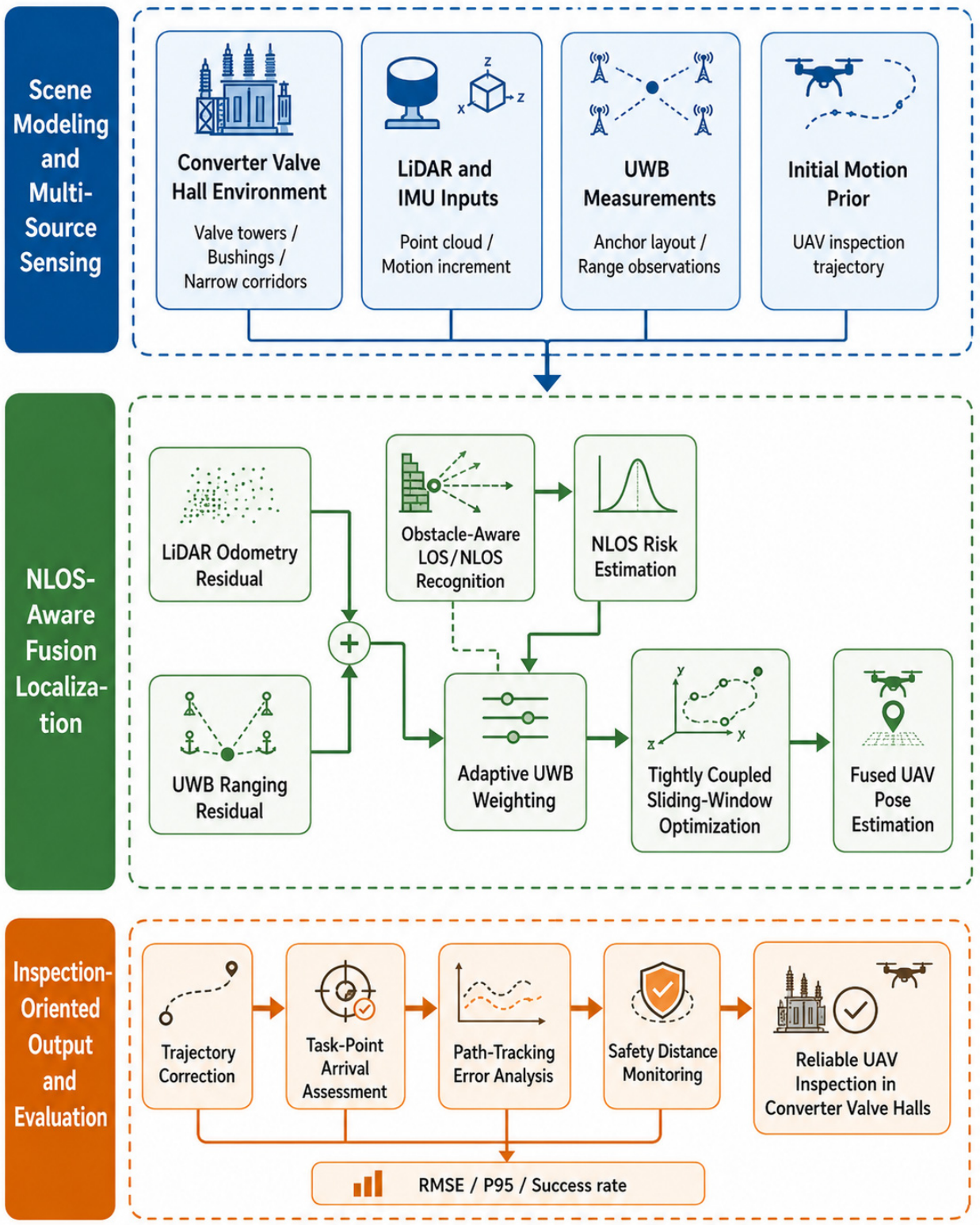
Different from post-processing fusion of LiDAR and UWB localization results, this paper adopts a tightly coupled strategy at the observation-residual level. LiDAR relative-motion constraints, UWB distance constraints, and NLOS-adaptive weights are jointly incorporated into the optimization framework. This strategy retains the original constraint information of both sensors and reduces the influence of abnormal ranging under local occlusion or multipath interference, thereby improving localization continuity, accuracy, and robustness in complex converter valve-hall environments. The overall framework of the proposed NLOS-aware LiDAR–UWB fusion localization method is shown in
Figure 1.
As shown in
Figure 1, the proposed method consists of three parts: scene modeling and multi-source perception, NLOS-aware fusion localization, and inspection-task-oriented output evaluation. First, the system forms the multi-source observation basis for localization using the valve-hall three-dimensional environment, LiDAR/IMU inputs, UWB ranging information, and the UAV initial motion prior. Second, in the fusion-localization layer, LiDAR odometry residuals and UWB ranging residuals are constructed separately. The geometric relationship between the obstacles and UWB links is used to identify NLOS risk, and UWB constraints are adaptively weighted accordingly. Finally, the tightly coupled sliding-window optimization outputs the fused UAV pose, which further supports inspection-trajectory correction, task-point arrival evaluation, path-tracking error analysis, and safety-distance monitoring.
3.1. Construction of LiDAR–UWB Observation Residuals
During UAV inspection, LiDAR odometry mainly provides relative displacement estimates between adjacent time instants. Such observations have good short-term continuity and can ensure local trajectory smoothness and motion consistency. However, in long corridors, repetitive valve-tower arrays, and locally degenerate point-cloud regions in converter valve halls, LiDAR odometry errors gradually accumulate with flight distance. Therefore, LiDAR observations are suitable as local motion constraints but should not independently undertake global localization correction.
Let the UAV trajectory position sequence to be estimated be as follows:
where p
k denotes the UAV position at the k-th discrete time instant and K denotes the number of trajectory points. According to the LiDAR-estimated adjacent position increment, the LiDAR motion-constraint error is constructed as follows:
where the residual term on the left-hand side of Equation (10) denotes the LiDAR motion-constraint error between time k − 1 and time k. Equation (10) represents the difference between the displacement estimated from two consecutive state variables and the LiDAR odometry increment; therefore, it is conceptually different from the state-sequence definition in Equation (9). If the estimated trajectory is consistent with the LiDAR odometry observation, this residual is small; otherwise, it increases. By introducing this residual, the fusion optimization maintains local trajectory continuity and avoids abrupt localization changes caused by UWB ranging fluctuations.
UWB observations provide distance constraints between the UAV and fixed anchors. Compared with LiDAR relative-motion constraints, UWB ranging has stronger global constraint capability and can correct accumulated LiDAR odometry drift. For the UAV position
and the j-th UWB anchor position
, the UWB ranging residual is defined as follows:
where
denotes the UWB distance residual, and
is the ranging value from the j-th anchor at time
. If the UWB measurement is under LOS propagation, this residual provides effective global correction for fusion localization. If the measurement is occluded by valve towers, bushings, or metallic frames, the residual may contain obvious NLOS positive bias.
LiDAR and UWB residuals play different roles in fusion localization. The LiDAR residual maintains local trajectory continuity and short-term motion consistency, whereas the UWB residual introduces global distance constraints and suppresses LiDAR drift. Their fusion is not a simple superposition; the constraint strength must be dynamically adjusted according to observation credibility. In converter valve halls, abnormal UWB ranging is often related to spatial occlusion. If LOS and NLOS conditions are not distinguished, introducing all UWB measurements into optimization with equal weights may distort the localization result. Therefore, a LiDAR-assisted UWB NLOS identification and adaptive weighting mechanism is developed next.
3.2. LiDAR-Assisted UWB NLOS Identification and Adaptive Weighting
UWB NLOS errors in converter valve halls are strongly scene-dependent. Valve towers, valve-side bushings, metallic support frames, and shielding structures not only block the direct UWB signal path but also cause reflection, diffraction, and multipath propagation. The UWB ranging result is then usually larger than the true distance and exhibits biased long-tailed error characteristics. If abnormality is judged only according to ranging residuals, the problem may not be detected until the localization result has already shifted. To improve the advance detection of ranging quality, this paper analyzes the spatial occlusion relationship between the UAV and UWB anchors using LiDAR point clouds or the known valve-hall geometric map.
Let the UAV position at time
be
and the j-th UWB anchor position be
. The line segment between them is expressed as follows:
This line segment can be regarded as the geometric approximation of the direct UWB propagation path. When the segment passes through valve towers, bushings, or other obstacles or when it is too close to obstacle surfaces, the corresponding ranging measurement is more likely to be affected by NLOS and multipath propagation. Considering modeling errors in point-cloud maps and obstacle boundaries, this paper adopts a distance-threshold form for NLOS risk identification:
where
is the NLOS indicator,
is the minimum distance from the line segment L_{j,k} to the obstacle set O, and
is the occlusion-risk threshold.
indicates that the UWB measurement has NLOS risk, whereas
indicates that the measurement is more likely to be under LOS conditions.
In real converter valve halls, however, UWB ranging quality is not simply “reliable” or “unreliable.” For example, when the signal line does not completely pass through an obstacle but is close to the edge of metallic equipment, the ranging value may still suffer from weak multipath effects. To describe this risk more continuously, an NLOS risk factor is further defined as follows:
where
is the distance between the UWB direct path and the nearest obstacle, and
is the distance-decay coefficient. When the line is far from obstacles,
is large and
approaches 0, indicating a reliable ranging observation. When the line is close to or passes through valve towers, bushings, or other equipment,
increases, indicating high NLOS risk.
After obtaining the NLOS risk factor, the UWB ranging-constraint weight is adjusted by modifying the equivalent ranging variance. Specifically, the UWB ranging variance is expressed as follows:
where
is the ranging variance under LOS conditions,
is the equivalent ranging variance under NLOS conditions, and
is generally larger than
. When the UWB measurement is reliable,
is small and the ranging variance approaches σLOS
2. When the measurement has high NLOS risk,
increases and the ranging variance approaches σNLOS
2.
The corresponding UWB observation weight is defined as follows:
According to Equation (16), UWB observations with good LOS conditions receive high weights and effectively correct LiDAR accumulated drift. UWB observations with NLOS risk are automatically down-weighted to prevent abnormal measurements from excessively affecting the fusion localization result. Compared with directly discarding suspicious measurements, adaptive down-weighting is smoother. It preserves part of the useful information when ranging quality decreases while reducing the destructive effect of erroneous observations.
This mechanism distinguishes the proposed method from ordinary LiDAR–UWB fusion localization. A conventional loosely coupled method usually obtains LiDAR and UWB localization results separately and then performs filtering or weighted fusion, which cannot fully exploit the original ranging constraints. A conventional tightly coupled method can jointly optimize LiDAR and UWB residuals, but abnormal UWB observations are directly introduced into the objective function if NLOS measurement quality is not considered. In this paper, LiDAR point clouds or the valve-hall geometric map is used to assist in judging UWB measurement credibility, enabling the fusion process to dynamically allocate observation weights according to the actual occlusion structure of the valve hall. This is more suitable for valve-hall inspection environments with dense metallic structures and regional NLOS distributions.
In the loose LiDAR-UWB baseline, LiDAR odometry and UWB localization are solved separately and then fused at the state-output level; therefore, individual UWB ranges do not directly participate in LiDAR trajectory optimization. In the ordinary tight LiDAR-UWB baseline, LiDAR motion residuals and UWB ranging residuals are optimized jointly, but all UWB measurements use fixed or uniform weights. In the proposed method, the UWB residual remains inside the tight optimization, but its information weight is updated according to the NLOS risk factor. This is the main algorithmic difference from both the loose and ordinary tight baselines.
3.3. Tightly Coupled Fusion Optimization and Algorithm Flow
After constructing LiDAR motion residuals, UWB ranging residuals, and adaptive weights, the UAV localization problem is formulated as a nonlinear least-squares optimization problem with robust constraints. The optimization objective is to solve the trajectory sequence that best satisfies the LiDAR local motion constraints and UWB global distance constraints under the given observations, while suppressing the influence of abnormal NLOS ranging.
Combining Equations (10) and (11), the objective function of the NLOS-aware LiDAR–UWB fusion localization can be written as follows:
where
is the optimized UAV trajectory position sequence,
is the information matrix of the LiDAR motion residual,
is the UWB ranging weight dynamically calculated from the NLOS risk, and
is the robust kernel function. The first term maintains local trajectory continuity, and the second term uses UWB ranging to provide global position constraints. Because the UWB weight varies with NLOS risk, the influence of abnormal ranging is significantly weakened, while reliable measurements can still effectively correct LiDAR accumulated drift.
To further reduce the effect of sudden abnormal ranging on localization results, the Huber robust kernel is introduced:
where
is the robust-kernel threshold. When the residual is small, the Huber kernel is consistent with ordinary quadratic loss and can maintain high estimation accuracy. When the residual is large, the loss function changes from quadratic growth to approximately linear growth, thereby suppressing the excessive influence of abnormal observations. For UWB ranging in converter valve halls, NLOS errors usually have sudden and biased characteristics, and the robust kernel can work together with adaptive weights to improve localization stability.
Because UAV inspection requires continuous online operation, global batch optimization over the entire trajectory would lead to computation that increases continuously with trajectory length. To balance localization accuracy and real-time performance, a sliding-window optimization strategy is adopted. Let the current optimization window length be
. The states estimated inside the window are the following:
The sliding window jointly optimizes only the recent UAV states, while historical states outside the window retain their effects through fixed priors or marginalization. This strategy effectively controls computation scale and is suitable for online localization in UAV inspection.
The execution process of the proposed method is as follows. First, the system reads the current LiDAR odometry increment and UWB ranging data and performs short-term prediction based on the previous localization result. Second, using LiDAR point clouds or the valve-hall geometric map, the system determines whether the line between the UAV and each UWB anchor approaches or passes through obstacle regions and computes the NLOS risk factor. Third, the equivalent variance and weight of each UWB ranging observation are updated according to the risk factor. Anchors with good LOS conditions retain high ranging weights, whereas anchors with occlusion or multipath risk are automatically down-weighted. Finally, LiDAR motion residuals and UWB ranging residuals are jointly constructed within the sliding window, and robust nonlinear optimization outputs the current fused UAV localization result. Algorithm 1 summarizes the complete procedure of the proposed localization method.
| Algorithm 1. NLOS-aware LiDAR–UWB fusion localization for UAV inspection in converter valve halls |
Input:
LiDAR odometry increment, UWB range measurement, UWB anchor position, obstacle map of the converter valve hall , sliding-window length, LOS ranging variance, NLOS equivalent variance, distance attenuation coefficient, and robust kernel threshold .
Output:
Fused UAV trajectory X*, NLOS risk factor ρj,k, adaptive UWB weight wj,kU, and current fused UAV position .
1: Initialize the UAV pose, sliding-window state, and sensor parameters.
2: Construct the initial state window X0w.
3: for each localization time step k = 1 to K do
4: Acquire the LiDAR odometry increment .
5: Acquire the UWB range measurements rj,k from all available anchors.
6: Predict the current UAV position using the LiDAR odometry increment.
7: Update the sliding-window state Xkw.
8: for each UWB anchor j = 1 to Na do
9: Construct the line segment Lj,k between the UAV and anchor j.
10: Compute the minimum distance dj,kobs from Lj,k to the obstacle map O.
11: if dj,kobs < dth then
12: Set the measurement condition as NLOS.
13: else
14: Set the measurement condition as LOS.
15: end if
16: Compute the NLOS risk factor ρj,k.
17: Update the equivalent ranging variance σj,k2.
18: Compute the adaptive UWB weight wj,kU.
19: end for
20: Construct the LiDAR odometry residuals within the sliding window.
21: Construct the UWB ranging residuals with adaptive weights.
22: Introduce the Huber robust kernel to suppress abnormal ranging residuals.
23: Solve the tightly coupled sliding-window optimization problem.
24: Output the current fused UAV position .
25: Remove outdated states and shift the sliding window forward.
26: end for
27: return X*, ρj,k, wj,kU, and . |
From the methodological perspective, LiDAR residuals, UWB residuals, adaptive weights, and the robust kernel play different roles. LiDAR residuals guarantee local trajectory continuity, UWB residuals provide global distance constraints, adaptive weights dynamically adjust ranging credibility according to the valve-hall occlusion structure, and the robust kernel further suppresses abnormal residuals. The four components jointly enable stable localization in converter valve halls where valve-tower occlusion, metallic multipath, and LiDAR geometric degeneration coexist.
The proposed method does not depend on a specific LiDAR SLAM front end. Any LiDAR front end that provides relative displacement or pose increments between adjacent frames can serve as the motion-constraint input in Equation (10). Similarly, UWB measurements may come from two-way ranging, time-of-arrival ranging, or other equivalent ranging mechanisms. The focus of this paper is how to combine converter valve-hall spatial structures to identify UWB ranging quality and reasonably allocate LiDAR and UWB observation weights during fusion. Therefore, the method has good modularity and can be integrated with existing LiDAR odometry, UWB localization, and path-tracking modules in UAV inspection systems.
4. Localization Performance Evaluation Model for Inspection Tasks
Section 3 constructed an NLOS-aware LiDAR–UWB fusion localization method whose core objective is to improve the continuity, accuracy, and robustness of UAV pose estimation in complex converter valve halls. However, for UAV inspection tasks, localization accuracy itself is not the final objective. The localization result ultimately supports inspection-trajectory tracking, task-point arrival, equipment-view maintenance, and safety-distance judgment. It is therefore insufficient to evaluate algorithm performance using only conventional localization-error indicators; the engineering applicability of localization methods should also be analyzed from the perspective of inspection-task execution.
In converter valve halls, localization errors have an amplified effect on inspection tasks. On the one hand, the passable space between valve towers, bushings, and support structures is narrow, so localization errors may cause the UAV to deviate from safe corridors and increase collision risk. On the other hand, inspection task points usually correspond to observation positions near equipment surfaces or key components. If localization errors are large, the UAV may not complete effective inspection at the specified distance and view angle, even when the overall trajectory shape is close to the reference path. Therefore, this paper constructs an evaluation model from both localization accuracy and inspection-task performance perspectives to comprehensively assess the proposed LiDAR–UWB fusion localization method.
4.1. Localization-Accuracy Evaluation Metrics
Localization-accuracy evaluation measures the deviation between the estimated trajectory and the true trajectory. Let the true UAV position at time k be
and the estimated position output by a localization algorithm be
. The corresponding position error is defined as follows:
where
denotes the three-dimensional localization error at the k-th trajectory point. This metric directly reflects instantaneous localization deviation and forms the basis for subsequent statistical indicators.
To evaluate the average localization accuracy over the entire inspection trajectory, the root-mean-square error (RMSE) is introduced:
where
is the number of trajectory points. RMSE is sensitive to large errors and reflects the overall error level of a localization algorithm during inspection. When significant drift or UWB abnormal ranging occurs in local regions, the RMSE increases accordingly. Therefore, this indicator is suitable for comparing the comprehensive accuracy of different localization methods.
In addition to mean-level errors, converter valve-hall inspection must consider the tail of the error distribution. Even if the average error is low, a few large instantaneous localization jumps may affect safety-distance judgment or task-point observation quality. Therefore, maximum localization error and 95th-percentile error are further used:
Here, represents the largest localization error during the entire inspection process and reflects the worst-case error bound. P95 indicates that 95% of trajectory points have errors no greater than this value and characterizes localization stability and tail risk. Compared with the maximum error, P95 is less sensitive to individual extreme outliers while still reflecting the distribution of high-error intervals.
In the simulation experiments, RMSE is mainly used to evaluate overall localization accuracy, P95 is used to evaluate the stability of localization results, and the maximum error is used to evaluate extreme-error risk. The combination of these three indicators avoids the concealment of local localization instability by a single average-error metric. In particular, for UWB-only localization or fusion methods without NLOS suppression, large ranging deviations may occur at some times and cause obvious trajectory jumps. In such cases, P95 and maximum error better reflect method deficiencies than the mean error alone.
4.2. UAV Inspection-Task Evaluation Metrics
At the inspection-task level, localization errors further affect whether the UAV can accurately reach task points, fly stably along the reference trajectory, and maintain sufficient safety distance from equipment. In addition to localization-accuracy indicators, this paper therefore introduces task-arrival error, inspection success rate, path-tracking error, and safety-distance metrics to evaluate the support capability of localization results for inspection tasks.
First, the task-arrival error is defined. Let the i-th inspection task point be
and the UAV estimated trajectory be
. The minimum arrival error corresponding to this task point is expressed as follows:
where
reflects how close the UAV estimated trajectory is to the i-th inspection task point. A small value indicates that the UAV can accurately reach or approach the task point, whereas a large value indicates that localization bias may prevent the UAV from entering the effective observation range. For key inspection positions such as valve-tower sides and bushing connections, task-arrival error directly affects image-capture distance and detection view angle.
Let the effective task-arrival radius be
. When
, the task point is considered successfully reached. The inspection-task success rate is defined as follows:
where
is the number of task points, and
is an indicator function that equals 1 when the condition is satisfied and 0 otherwise. This metric evaluates the practical effect of the localization method from the perspective of task completion. Unlike RMSE,
focuses more on whether localization errors have affected inspection-task execution. If a method has a moderate overall RMSE but produces large deviations near key task points, its task success rate may still decrease significantly.
Second, a path-tracking error is considered. UAV inspection is usually performed along a reference or planned trajectory to ensure flight continuity and a specified equipment-observation order. Let the reference inspection trajectory be
. The average tracking error of the estimated trajectory relative to the reference trajectory is defined as follows:
where
represents the average deviation of the estimated trajectory from the reference trajectory. This metric reflects the potential influence of localization results on trajectory-tracking control. If the localization result has long-term drift, the UAV may gradually deviate from the reference inspection corridor even when the local trajectory remains continuous. If instantaneous jumps occur, the controller may misjudge the UAV state and produce unnecessary attitude adjustments or path corrections.
Finally, safety-distance evaluation is revised to compare the true distance-to-obstacle and the estimated distance-to-obstacle rather than relying only on the minimum distance calculated from the estimated trajectory. The true obstacle distance at a given time step is the distance between the true UAV position and the obstacle set, while the estimated obstacle distance is calculated from the estimated UAV position. The distance-assessment error is the absolute difference between these two distances and is used for subsequent false-judgment analysis. A false-safe case occurs when the estimated distance is above the safety threshold while the true distance is below it, whereas a false-alarm case occurs when the estimated distance is below the threshold while the true distance is actually safe.
The minimum estimated safety distance is retained only as an auxiliary indicator. The main safety-related metrics used in the revised evaluation are the mean distance-assessment error, the false-safe rate, and the false-alarm rate. This revision avoids interpreting a larger estimated minimum distance as direct evidence of safer real flight.
In summary, this paper adopts an evaluation system that combines localization accuracy, task execution, and safety-margin assessment. RMSE, P95 error, and maximum error evaluate localization precision and stability. Task-arrival error and inspection success rate measure task completion. The tracking error, distance-assessment error, false-safe rate, and false-alarm rate evaluate the influence of localization errors on safety-related judgment.
5. Simulation Experiments and Result Analysis
To verify the effectiveness and limitations of the proposed NLOS-aware LiDAR-UWB fusion localization method, a simulation environment based on a typical internal converter valve-hall structure is constructed. The revised experiments include a main closed-loop inspection path, NLOS robustness tests, LiDAR-degeneration tests, UWB-anchor-number sensitivity tests, inspection-task evaluation, ablation experiments, and additional Monte Carlo statistical tests under different trajectories, anchor layouts, anchor installation errors, and obstacle densities. Because real energized valve-hall flight data were not available in this revision, the conclusions are restricted to simulation and randomized robustness validation.
5.1. Simulation Scenario and Experimental Settings
Taking UAV autonomous inspection in converter valve halls as the application background, this paper constructs a three-dimensional simulation scenario. The scenario contains a double-row suspended valve-tower array, with six valve-tower modules in each row. The wall-side bushings are not simply arranged uniformly along the wall; instead, they are modeled according to typical functional partitions. Two groups of three-phase AC-side bushings are arranged on one wall, and a small number of grouped bushings related to DC pole lines and neutral lines are arranged on the other wall. This modeling strategy avoids simplifying bushings into ordinary uniformly distributed wall obstacles and better conforms to the engineering characteristics of converter valve-hall equipment arranged by functional regions.
All UWB anchors are deployed inside the converter valve hall, mainly near the upper inner wall, roof beams, or internal fixed support structures rather than outside the hall. This setting is consistent with the basic engineering layout of UWB localization systems in indoor GNSS-denied environments. The UAV reference inspection trajectory is located within safe corridors between the valve-tower arrays and wall-side bushings. Thirty-four inspection task points are set around valve-tower sides, bushing-connection areas, and corridor boundaries. The trajectory is discretized into 273 sampling points to simulate a closed-loop inspection process inside the valve hall.
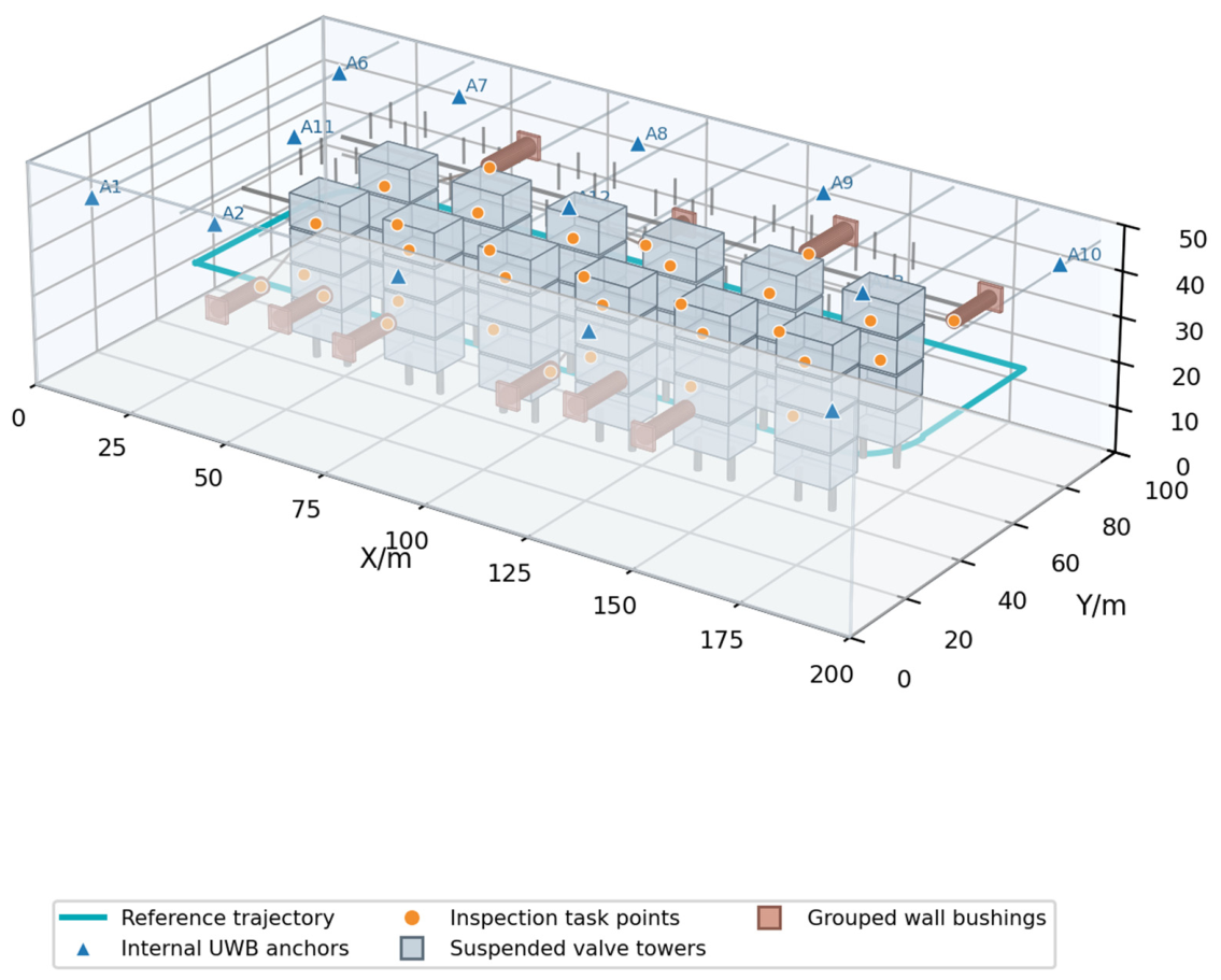
As shown in
Figure 2, the constructed scenario includes suspended valve towers, wall-side bushing groups, internal UWB anchors, inspection task points, and a UAV reference inspection trajectory. UWB anchors are deployed on the internal boundaries and upper regions of the valve hall to provide global ranging constraints for the UAV. The inspection trajectory extends along the safe corridor between valve towers and wall-side equipment and covers valve-tower sides and bushing-related observation positions. This scenario contains both relatively open corridor areas and regions close to valve-tower occlusion and bushings, making it suitable for testing the adaptability of LiDAR–UWB fusion localization in typical converter valve-hall environments.
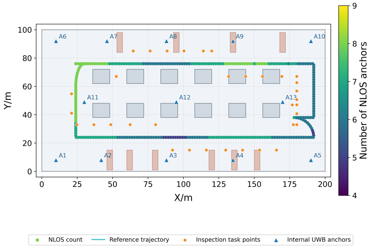
To further illustrate the relationship between UWB ranging quality and spatial structure,
Figure 3 presents the internal UWB anchor deployment and the NLOS distribution along the UAV inspection trajectory.
Figure 3 shows that all UWB anchors are deployed near the internal walls or upper support structures of the valve hall, rather than outside the hall. The number of NLOS anchors along the trajectory changes with the UAV position. When the UAV approaches valve-tower arrays, wall-side bushing groups, and connecting conductors, some UWB measurements are more likely to be affected by occlusion and multipath. This result shows that the simulation scenario reflects the spatial-structure-dependent variation in UWB ranging quality in converter valve halls and provides a validation basis for the NLOS-aware adaptive weighting strategy.
Five localization methods are compared: LiDAR-only, UWB-only, loose LiDAR–UWB, tight LiDAR–UWB, and the proposed method. LiDAR-only relies only on LiDAR odometry increments for recursive localization. UWB-only relies only on UWB ranging for position estimation. Loose LiDAR–UWB denotes a loosely coupled fusion method. Tight LiDAR–UWB denotes a tightly coupled fusion method without NLOS identification. The proposed method denotes the NLOS-aware tightly coupled LiDAR–UWB fusion localization method developed in this paper. To ensure fair comparison, all methods use the same reference trajectory, UWB anchor positions, task-point positions, and sensor-error settings.
Table 1 summarizes the main simulation and optimization parameters.
During the simulation, LiDAR odometry is modeled as a relative-motion observation with random error and accumulated drift. To avoid an overly easy NLOS-identification problem, the NLOS generation model is not identical to the geometric risk model used by the proposed algorithm. NLOS ranging errors are generated by a stochastic model that jointly considers link-obstacle proximity, anchor range, random metallic multipath bursts, and a positive long-tailed bias. The proposed method only uses the geometric risk factor to adjust UWB weights and does not access the true NLOS label generated in the simulation.
5.2. Localization Accuracy Comparison on a Typical Inspection Path
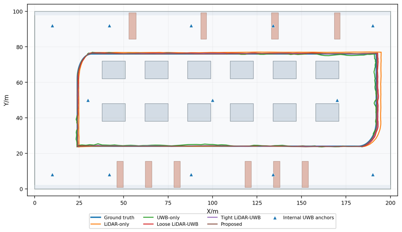
The trajectory-estimation performance of different localization methods is first compared on a complete closed-loop inspection path in the converter valve hall.
Figure 4 shows the planar trajectory comparison.
As shown in
Figure 4, the LiDAR-only method follows the true trajectory well in the early part of the path. However, as the UAV continues to fly along the valve-tower corridor, accumulated drift increases and the later trajectory obviously deviates from the reference path. The UWB-only method provides global distance constraints in some regions, but it suffers from trajectory jitters and local offsets in valve-tower occlusion and bushing-adjacent regions because of NLOS ranging. The loose LiDAR–UWB method integrates information from both sensors to some extent, but its shallow fusion level gives limited ability to suppress abnormal UWB measurements. The tight LiDAR–UWB method improves trajectory consistency through residual-level fusion, but it can still be affected by erroneous UWB constraints when LOS and NLOS observations are not distinguished. In contrast, the trajectory estimated by the proposed method is closest to the true trajectory and maintains good continuity and stability even in regions with significant valve-tower occlusion.
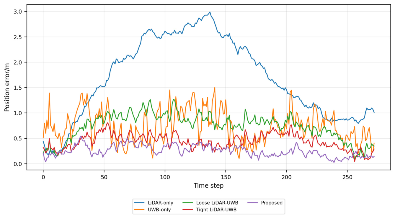
Figure 5 further shows the time series of localization errors for different methods.
Figure 5 indicates that the position error of the LiDAR-only method shows a clear accumulated trend with flight time, demonstrating that LiDAR odometry alone cannot avoid long-distance drift. The UWB-only error does not accumulate monotonically, but it fluctuates significantly in NLOS regions, reflecting the high sensitivity of UWB ranging to metallic occlusion and multipath. Loose LiDAR–UWB and tight LiDAR–UWB reduce part of the error, but the former insufficiently suppresses abnormal ranging, and the latter still exhibits local error peaks in high-NLOS regions. The proposed method maintains a relatively low overall error curve, and no obvious long-term drift or abrupt jumps occur during the inspection process.
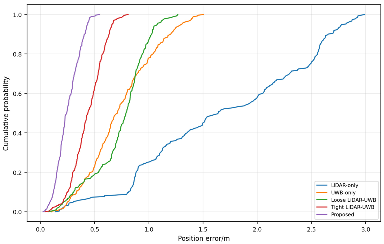
Figure 6 presents the cumulative distribution of localization errors for different methods.
As shown in
Figure 6, the error distribution of the proposed method is closest to the left side, indicating that most trajectory points have low localization errors. In contrast, LiDAR-only exhibits an obvious long-tailed distribution, indicating large, accumulated drift in the later inspection segment. UWB-only and loose LiDAR–UWB outperform LiDAR-only but remain affected by NLOS ranging. The error distribution of tight LiDAR–UWB is further converged, but it is still inferior to that of the proposed method. This result shows that the proposed method reduces not only average localization error but also improves the stability of the error distribution.
Table 2 shows that the proposed method achieves the best localization performance among all compared methods. The RMSE, mean error, P95 error, and maximum error are 0.30 m, 0.29 m, 0.43 m, and 0.48 m, respectively. The P95 values in the fourth column were rechecked using the 95th percentile of the pointwise position-error sequence. To avoid ambiguity in the percentage calculation, the RMSE reduction is calculated as RMSE reduction (%) = [(baseline RMSE − proposed RMSE)/baseline RMSE] × 100%. Based on the rounded RMSE values listed in
Table 2, the proposed method reduces the RMSE by 50.0%, 58.9%, 55.2%, and 80.5% compared with ordinary tight LiDAR-UWB fusion, loose LiDAR-UWB fusion, UWB-only localization, and LiDAR-only localization, respectively.
The runtime unit “ms/pose” is obtained by dividing the total execution time of a localization method by the number of estimated poses and converting the result into milliseconds. It is calculated as runtime per pose (ms/pose) = 1000 × total runtime (s)/number of estimated poses. Here, total runtime denotes the computation time over the whole trajectory, and the number of estimated poses equals the number of trajectory samples used in the localization evaluation. The average runtime per pose of the proposed method is 0.14 ms in the simulation implementation, which is slightly higher than those of the baseline methods because of NLOS risk evaluation, adaptive weight updating, and robust optimization. Nevertheless, the runtime remains below the millisecond level in the tested scenario and satisfies the computation requirement of the localization layer in the simulation environment.
5.3. Robustness Under NLOS and LiDAR Degeneration Conditions
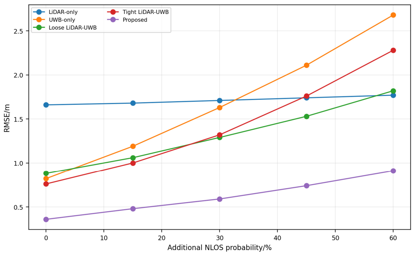
As shown in
Figure 7, the error of the UWB-only method increases most significantly with NLOS probability. This is because UWB-only lacks constraints from other sensors, and localization results shift directly once ranging is affected by NLOS bias. Tight LiDAR–UWB performs well under low NLOS conditions, but when the NLOS ratio increases, abnormal UWB measurements are directly introduced into the tightly coupled optimization, leading to an obvious error increase. Loose LiDAR–UWB fuses the two types of observations, but its robustness remains limited because measurement quality is not explicitly identified. In contrast, the proposed method exhibits the smallest error growth with increasing NLOS probability, and its RMSE remains 0.91 m under 60% additional NLOS probability. This confirms that NLOS risk identification and adaptive down-weighting effectively weaken the influence of abnormal UWB observations.
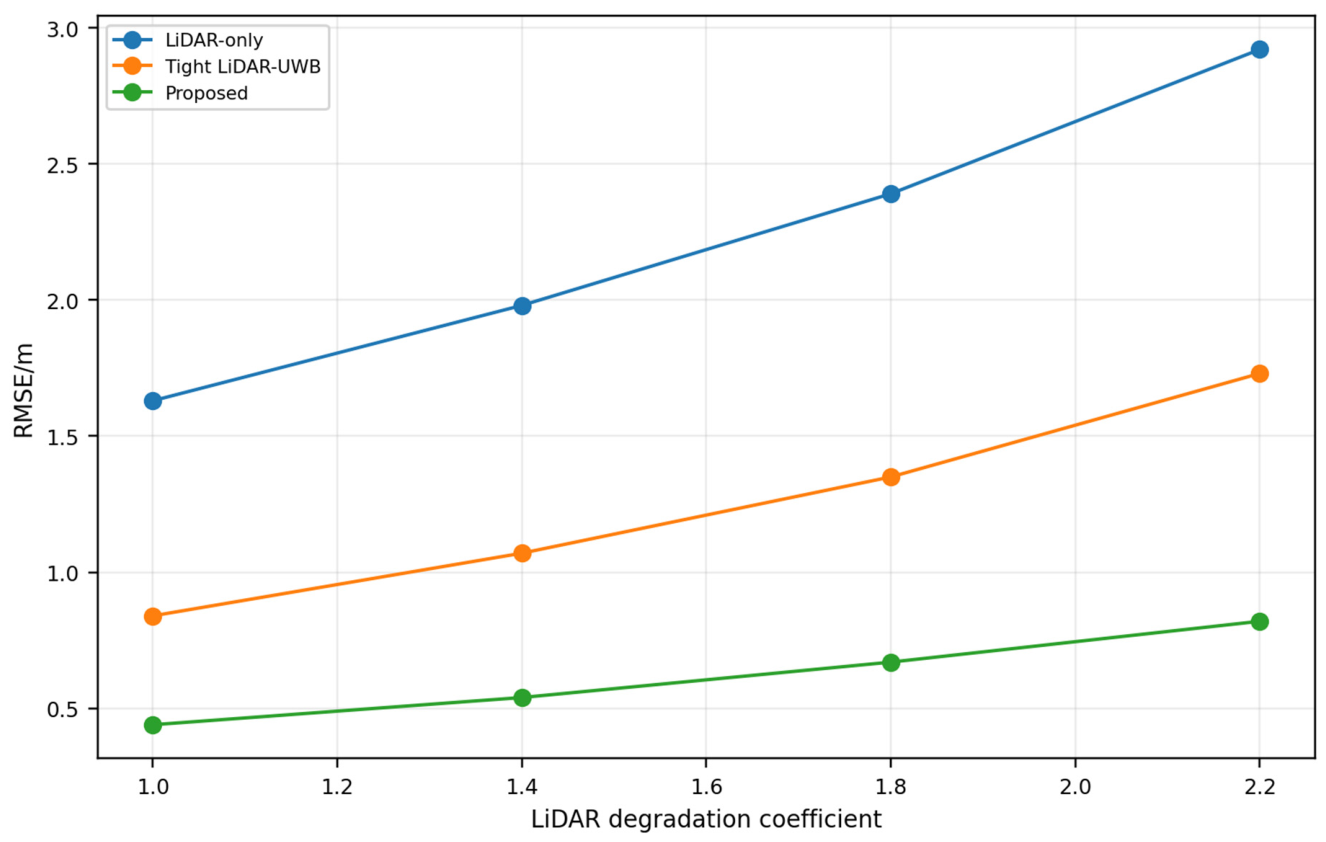
Second, LiDAR geometric degeneration in repetitive valve-tower arrays and narrow corridors is considered. The LiDAR degeneration coefficients are set to 1.0, 1.4, 1.8, and 2.2. The results are shown in
Figure 8.
Figure 8 shows that the error of LiDAR-only increases significantly with the LiDAR degeneration coefficient, indicating that LiDAR odometry alone easily accumulates drift in repetitive structural regions of converter valve halls. Tight LiDAR–UWB introduces global UWB ranging constraints and therefore grows more slowly than LiDAR-only. However, when UWB ranging simultaneously contains NLOS bias, its localization stability is still affected. The proposed method maintains the lowest RMSE under all degeneration coefficients, showing that reliable UWB constraints effectively suppress LiDAR drift, while the NLOS down-weighting mechanism prevents abnormal measurements from damaging the fusion result.
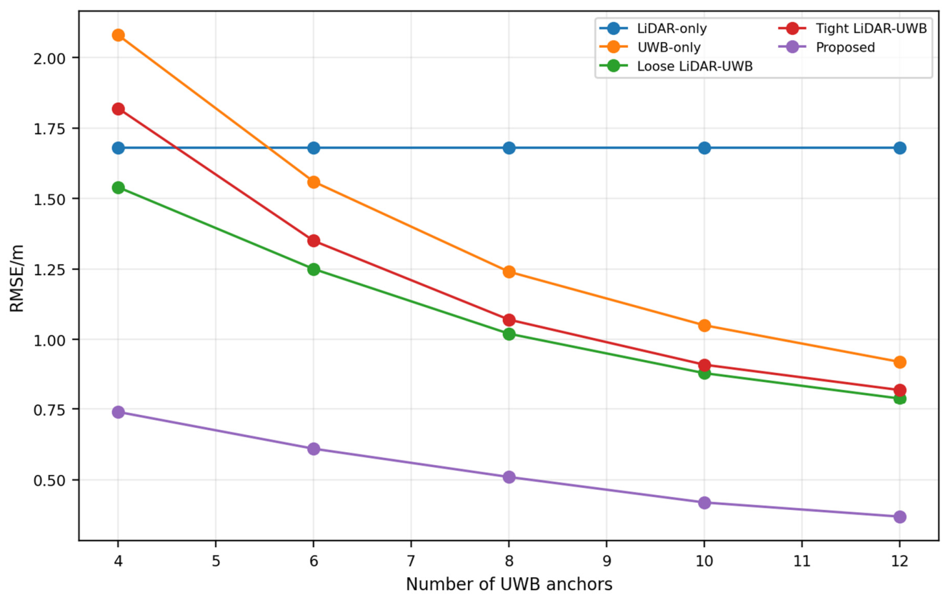
Third, the influence of the number of UWB anchors on localization performance is analyzed. The number of UWB anchors is set to 4, 6, 8, 10, and 12, and the RMSE variation in different methods is compared in
Figure 9.
As shown in
Figure 9, when the number of UWB anchors is small, the UWB-only and tight LiDAR–UWB methods have large errors because anchor geometry is insufficient and some anchor measurements are strongly affected by occlusion. As the number of anchors increases, the localization errors of UWB-only, loose LiDAR–UWB, and tight LiDAR–UWB decrease. The proposed method always maintains the lowest RMSE under different numbers of anchors and gradually becomes stable as the number increases. This demonstrates that the proposed method can use additional UWB constraints to improve localization accuracy and can also maintain good robustness when the number of anchors is limited through LiDAR motion constraints and ranging-quality assessment.
Overall, the experiments show that the proposed method remains stable under enhanced UWB NLOS conditions, aggravated LiDAR geometric degeneration, and varying numbers of UWB anchors. Its advantage arises from two aspects. On the one hand, LiDAR odometry provides continuous motion constraints and prevents trajectory jumps caused by UWB ranging fluctuations. On the other hand, UWB ranging provides global constraints, and NLOS-risk down-weighting prevents abnormal measurements from exerting excessive influence on localization results.
5.4. Localization Application Effect for Inspection Tasks
Localization methods ultimately serve UAV inspection tasks. Therefore, in addition to localization-accuracy indicators, this paper evaluates the influence of different methods on inspection-task execution using task-arrival error, path-tracking error, minimum safety distance, and inspection success rate.
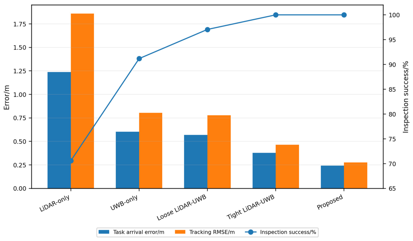
Figure 10 compares the inspection-oriented performance indicators of different localization methods.
Figure 10 shows that the LiDAR-only method is affected by accumulated drift and produces large task-arrival, tracking, and distance-assessment errors. UWB-only localization is less affected by long-term drift, but it still suffers from NLOS-induced local error peaks. Loose and ordinary tight LiDAR-UWB fusions improve task execution, but their distance-assessment errors and false-safe rates remain higher than those of the proposed method. The proposed method achieves the lowest normalized task and safety-assessment errors while maintaining a 100% inspection success rate.
As shown in
Table 3, the average task-arrival error of the proposed method is 0.42 m, which is lower than that of ordinary tight LiDAR-UWB fusion. Its distance-assessment MAE is 0.14 m, and the false-safe and false-alarm rates are 3.7% and 0.7%, respectively. This revised analysis compares true and estimated obstacle distances and therefore provides a more appropriate interpretation of the safety-related localization effect.
Table 4 lists the detailed false-safe and false-alarm statistics for safety-distance judgment.
From the safety-distance perspective, the larger estimated minimum distance of the proposed method is no longer interpreted as direct evidence that the UAV truly flies farther away from equipment. Instead, the revised analysis focuses on how accurately each localization method estimates the obstacle distance. The proposed method yields the smallest distance-assessment error and fewer false safety judgments, which indicates a lower risk of misleading the downstream path-tracking or safety-monitoring module.
It is worth noting that both tight LiDAR–UWB and the proposed method achieve a 100% inspection success rate, but they are not equivalent. Tight LiDAR–UWB satisfies the task-arrival rate requirement, but its localization error, task-arrival error, and path-tracking error are higher than those of the proposed method. This indicates that task success rate alone is insufficient for evaluating localization methods. Localization accuracy and task-execution quality should also be considered. The advantage of the proposed method is that it further improves inspection-pose approach accuracy and trajectory stability while ensuring 100% task arrival.
5.5. Statistical Robustness, Ablation, and Computational Efficiency Analysis
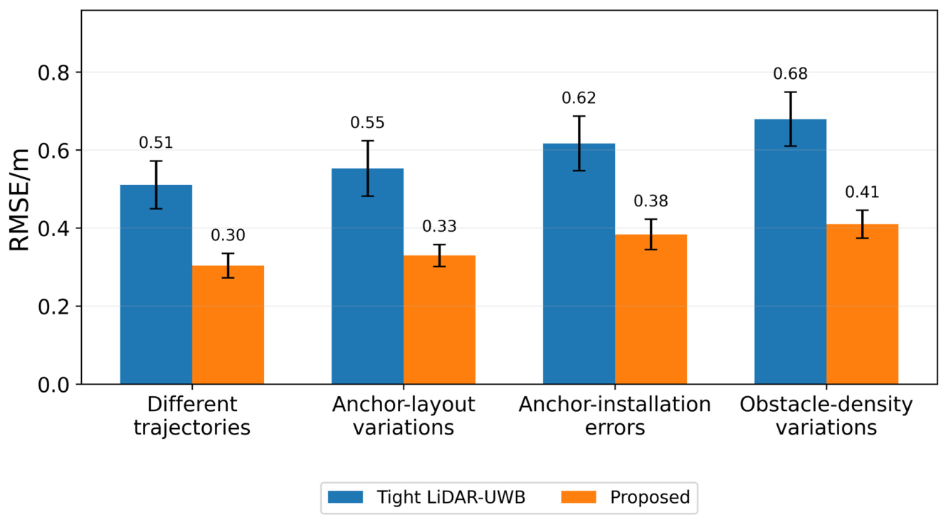
To supplement the single-trajectory validation, Monte Carlo experiments were conducted under four types of perturbations: different inspection trajectories, different UWB-anchor layouts, anchor installation errors, and different obstacle densities. Each scenario was repeated 30 times using independent ranging noise, odometry noise, and stochastic NLOS disturbances. The ordinary tight LiDAR-UWB method and the proposed method were compared using paired statistical tests. The corresponding RMSE distributions are further visualized in
Figure 11.
Figure 11 and
Table 5 show that the proposed method consistently outperforms ordinary tight LiDAR-UWB fusion under all tested perturbations. The fourth column in
Table 5 was re-estimated from the mean RMSE values in the second and third columns using the same calculation rule: RMSE reduction (%) = [(baseline RMSE − proposed RMSE)/baseline RMSE] × 100%. After recalculation, the RMSE reductions range from 38.7% to 41.2%, and all paired tests indicate statistically significant improvements (
p < 0.001). These results address the sensitivity to trajectory selection, anchor layout, installation errors, and obstacle density.
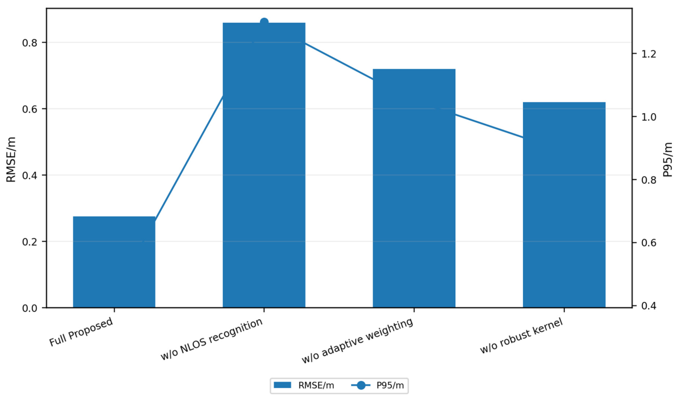
To verify the necessity of the key modules in the proposed method, ablation experiments are further conducted. The variants compared include the full proposed method, a version without NLOS identification, a version without adaptive weighting, and a version without the robust kernel.
Figure 12 shows the ablation results.
Figure 12 and
Table 6 show that removing NLOS identification increases the RMSE to 0.86 m, indicating that abnormal ranging significantly affects the fusion result if UWB measurement quality is not judged according to valve-hall geometric occlusion. Removing adaptive weighting increases the RMSE to 0.72 m, showing that even if NLOS risk can be identified, abnormal UWB residuals cannot be sufficiently suppressed without weight adjustment during optimization. Removing the robust kernel gives an RMSE of 0.62 m, confirming that the robust kernel also contributes to suppressing sudden abnormal ranging. The full proposed method achieves the lowest RMSE, P95 error, and maximum error. The runtime values in
Table 6 are calculated using the same ms/pose definition as in
Table 2, namely total execution time divided by the number of optimized poses and multiplied by 1000.
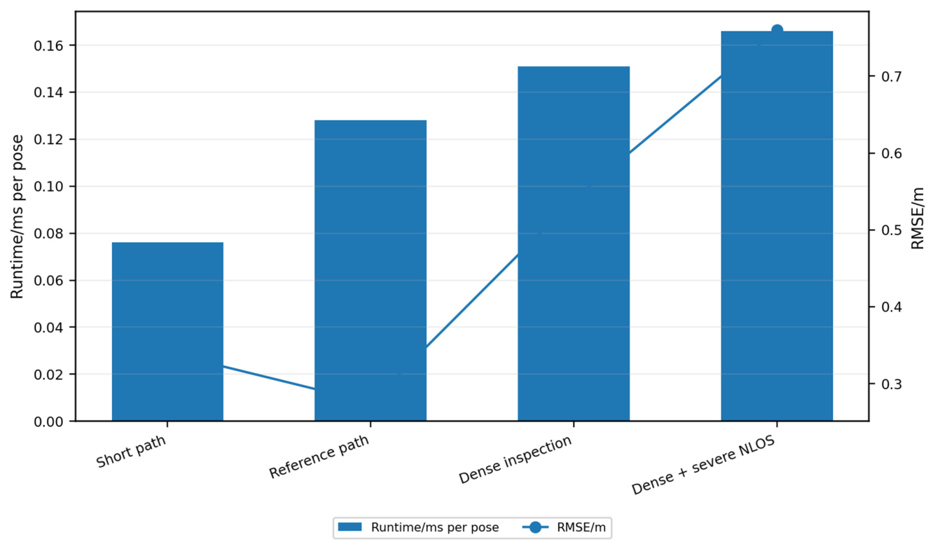
Finally, computational efficiency and scalability are analyzed. Four task scales, namely short path, reference path, dense inspection, and dense plus severe NLOS, are set to evaluate runtime and localization-error variation under different trajectory lengths and observation complexities. The results are shown in
Figure 13.
Figure 13 shows that as the number of trajectory points increases and NLOS conditions become more severe, the runtime per pose of the proposed method increases from 0.076 ms to 0.166 ms, and the localization RMSE increases from 0.34 m to 0.76 m. This trend is consistent with practical localization problems: when the trajectory is longer, task points are denser, or NLOS is more severe, the number of optimization constraints and the proportion of abnormal observations increase, causing both computation and error to rise. Nevertheless, even in the dense plus severe NLOS scenario, the runtime per pose remains below 0.2 ms, indicating good computational efficiency at the current simulation scale.
Overall, the experimental results demonstrate that, in the grouped-bushing converter valve-hall simulation scenario, the proposed method effectively suppresses LiDAR odometry accumulated drift and UWB NLOS ranging errors. It outperforms the comparison methods in localization accuracy, error stability, task-point arrival, tracking error, and distance-assessment reliability. The revised validation also shows that the method does not rely on a deterministic equivalence between NLOS generation and NLOS detection; rather, it improves localization under stochastic NLOS and multipath disturbances by using geometry-aware adaptive weighting.
5.6. Engineering Applicability and Limitations
The proposed method should be interpreted as a localization-layer method for GNSS-denied, metallic, NLOS-prone indoor inspection environments. It does not by itself solve all problems of UAV operation in energized converter valve halls. In practical deployment, the UAV should rely on onboard autonomous control, preplanned or locally corrected trajectories, and fail-safe flight-control logic; UWB ranging is used for localization support and should not be regarded as the manual control link. Therefore, the applicability of the method depends on the electromagnetic compatibility of the UAV platform, the UWB system, the onboard computer, and the communication system.
For high-voltage converter valve halls, the most appropriate initial application scenarios are maintenance windows, outage inspection, low-interference commissioning periods, or controlled indoor environments with electromagnetic shielding and safety isolation. Full deployment in an energized valve hall requires field UWB ranging tests, real LiDAR point-cloud acquisition, electromagnetic-interference assessment, communication-link reliability tests, and closed-loop flight validation. The revised manuscript explicitly limits its conclusions to simulation and robustness validation and regards real valve-hall experiments as necessary future work rather than as an already demonstrated result.