Article

Effect of Foreign Object Damage on Corrosion Fatigue Behavior in Surface-Strengthened EA4T Railway Axle Steel

1
School of Mechanical Engineering, Chengdu University, Chengdu 610106, China
2
Sichuan Zichen Technology Co., Ltd., Chengdu 611500, China
3
Sichuan Aerospace Zhongtian Power Equipment Co., Ltd., Chengdu 610100, China
4
State Key Laboratory of Rail Transit Vehicle System, Southwest Jiaotong University, Chengdu 610031, China
*
Author to whom correspondence should be addressed.
Technologies 2025, 13(8), 368; https://doi.org/10.3390/technologies13080368
Submission received: 29 June 2025 / Revised: 8 August 2025 / Accepted: 13 August 2025 / Published: 17 August 2025
(This article belongs to the Section Innovations in Materials Science and Materials Processing)

Abstract

The electrochemical behavior and corrosion fatigue property of the surface-strengthened EA4T axle steel subjected to foreign object damage (FOD) is investigated in this study. It is found that the corrosion resistance can be enhanced after being impacted by the foreign object due to the introduced hardening layer. Specifically, compared to the smoothed sample, the 167 m/s sample exhibited a 13.88% higher corrosion potential (Ecorr) and a 67.61% lower current density (icorr). The facture surface demonstrates that the corrosion pits on the surface are the main crack initiation location for the smoothed specimens. In contrast, for the surface-damaged specimens, cracks initiate around the crater. The foreign object impact speed has a significant influence on the corrosion fatigue strength; specifically, the faster the impact velocity, the greater the surface damage of the axle specimen, and the shorter its fatigue life at the same stress level. To address the combined influence of size effect and surface defects on fatigue performance, we constructed an improved Kitagawa–Takahashi (KT) diagram by incorporating the theoretical corrosion fatigue limit of full-scale axles with a surface damage of 270 MPa based on conditional probability density function (CPDF). Comparative analysis demonstrates that the revised KT diagram defines a narrower yet more conservative fatigue loading safety zone than the standard KT diagram. This refinement enhances reliability in practical applications where surface imperfections and scale effects dominate failure mechanisms.

1. Introduction

A high-speed railway transportation system is not only a vital symbol of industrial modernization, but also an important pillar of economic development. As a critical load-bearing component in high-speed trains, the axle’s reliability directly impacts train safety and stability [1,2]. However, inevitable defects introduced during axle production, transportation, service, or maintenance may initiate and propagate cracks under rotating bending loads, potentially causing catastrophic axle fractures [2,3]. Defects are the primary cause of fatigue failure in railway axles [4].
An investigation of EA4T and S38C axle surfaces reveals that foreign object damage (FOD) accounts for 55% of defects in EA4T axles and 49% in S38C axles [5]. Obviously, FOD represents a primary failure mechanism in modern high-speed railway axles. Previous studies demonstrate that the foreign object impact mainly occurs between 950 mm and 1160 mm from the end of the axle opposite the gearbox [6]. These defects form substantial surface craters, compromising axle integrity and accelerating fatigue strength degradation, thereby reducing service life [7]. Gao et al. [8,9] demonstrated that surface damage from foreign object impacts is a key factor in the fatigue performance degradation of high-speed railway axles. Both qualitative and quantitative assessment of this damage is essential for axle maintenance.
The expansion of China’s high-speed railways, especially in coastal and acid rain-prone regions, exposes axles to increasingly corrosive environments that threaten operational integrity. These conditions compromise axle structural integrity, accelerating fatigue damage and promoting premature failure. The synergistic effect of corrosive media and cyclic stresses significantly compromises the fatigue integrity of axle steel, primarily through anodic dissolution at crack tips, hydrogen embrittlement, and residual stress relaxation, collectively accelerating crack initiation and propagation [10,11].
Consequently, developing an accurate predictive model for the fatigue strength of railway axles under corrosive conditions is crucial, which would not only enhance the design and maintenance of axles but also improve safety and reduce long-term operational costs. According to improve the Murtaza and Akid models, Beretta et al. [12] demonstrated accurate prediction capability for the corrosion fatigue life of EA1N-grade axle steel in simulated rainwater environments. Zhao et al. [13] developed a corrosion fatigue life prediction model integrating corrosion kinetics and equivalent defect size theory, demonstrating strong correlation between predicted and experimental results at high stress levels across multiple stress cycles. For EA4T axles containing introduced scratch defects, the El-Haddad-modified Kitagawa–Takahashi (KT) model proves effective in assessing both fatigue and corrosion fatigue strength of defect-sensitive components [14].
Appropriate surface strengthening techniques can generate high-hardness microstructures and compressive residual stresses (CRSs), enhancing fatigue performance through dual-phase surface modification [15]. Current surface enhancement methodologies for railway axles comprise two principal classifications: surface deformation strengthening and surface phase transformation strengthening. The former primarily incorporates shot peening and rolling technology, while the latter encompasses induction hardening, carburization, nitriding, and carbonitriding treatments. Ultrasonic surface rolling processing (USRP), as a new surface strengthening technology, combines ultrasonic vibration with traditional rolling to carry out micro-amplitude high-speed impact and rolling treatment on metal surface to produce plastic deformation, thus improving the surface state of materials, introducing compressive residual stress, and enhancing wear resistance, corrosion resistance, and fatigue resistance [16]. Experimental analysis demonstrates that optimized USRP parameters, determined through orthogonal experimental design, enhance the rotating–bending fatigue strength of EA4T axles by 46.9% through controlled surface plastic deformation [17].
Defects and corrosion pits inevitably formed on the surface of axles operating in extreme environments are significant factors leading to the degradation of fatigue performance. Although considerable attention has been paid to the surface strengthening of axles, defect behavior characterization, fatigue life prediction, and the exploration of corrosion fatigue properties, there remains a gap in the research regarding the in-depth revelation of the damage mechanisms of axles under the coupled effects of surface strengthening, foreign object damage, and corrosive environments, as well as the exploration of corrosion fatigue strength assessment for strengthened defected axles considering the competitive effects between defects and corrosion pits.
This study systematically evaluates the corrosion and corrosion fatigue mechanisms in the surface-enhanced EA4T axle steel under controlled foreign object damage conditions. To this end, the macroscopic and microscopic characterization were conducted on the surface-impacted crater. The electrochemical and corrosion fatigue tests were conducted on the USRPed + unFODed and USRPed + FODed axle specimens. Within the defect-tolerant design framework, the theoretical corrosion fatigue limit of full-scale axle with surface damage was used to build the improved Kitagawa–Takahashi (KT) diagram.

2. Materials and Methods

2.1. Specimen Preparation

This study focuses on EA4T (25CrMo4) axle steel, which is commonly used in high-speed railways. The chemical composition of this steel includes the following, as shown in Table 1 [1]:
High cycle fatigue (HCF) specimens were taken along the axial direction in the region prone to foreign object impact of the axle (see Figure 1).
USRP was applied to EA4T steel axle specimens using an HK30C ultrasonic pro-cessing device (Shandong Huayun Mechanical & Electrical Technology Co., Ltd., Jinan, China). A tungsten carbide/cobalt (WC/Co) ball (surface roughness: 0.1 μm, hardness: 80 HRC) was rolled over the specimen surface under ultrasonic excitation (frequency: 12.6 kHz) to induce cyclic plastic deformation. Based on our previous research results, the static pressure, rolling pass, feed, and rotation speed were set as 1085 N, twice, 0.12 mm/r, and of 50 r/min, respectively [18].

2.2. FOD Experiments

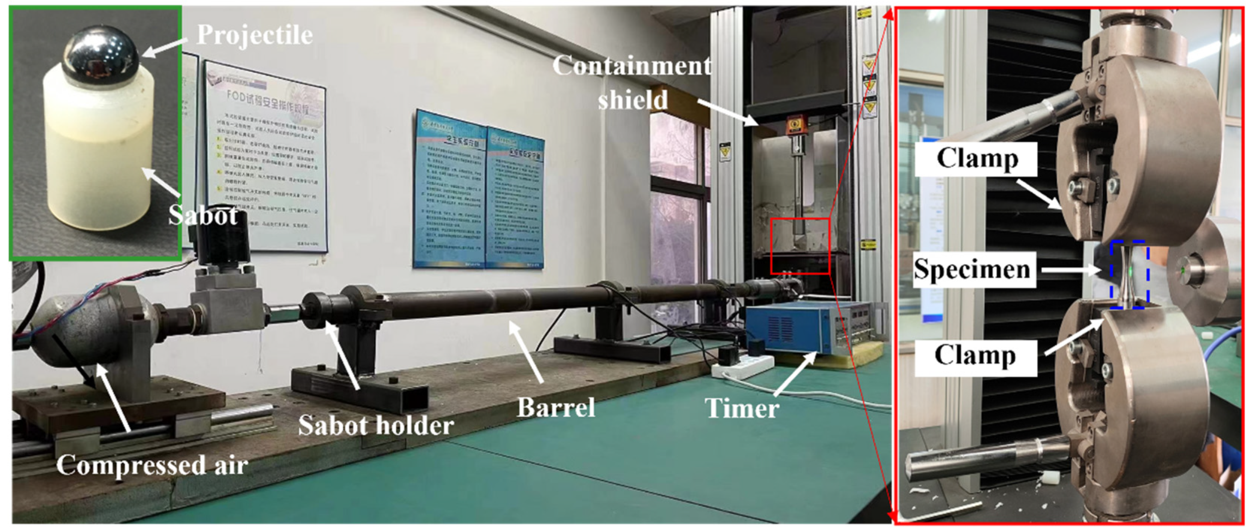
The controlled foreign object damage experiment was executed using a calibrated compressed gas gun system, wherein spherical projectiles were accelerated to prescribed velocities for precise impact on EA4T steel specimens. Spherical projectiles of 2 mm diameter, made of GCr15 bearing steel (hardness: ~65 HRC), were selected to replicate high-velocity impacts typical of industrial FOD scenarios (see Figure 2). In the process of projectiles impact, the air chamber was first filled with a quantitative amount of high-pressure nitrogen gas, and the impact velocity of the sphere was regulated by controlling the amount of high-pressure nitrogen. Considering the operation of high-speed trains, the impact speeds of the projectiles were set to the designed operating speed of 360 km/h (about 100 m/s) for the Fuxing train and the new high-speed railway developed in China with a speed of 600 km/h (approximately 167 m/s). The impact angle was aligned orthogonally to the specimen surface in accordance with standardized testing protocols. Following this, the EA4T steel specimens were prepared as USRPed + unFODed, USRPed + FODed-v = 100 m/s and USRPed + FODed-v = 167 m/s to investigate the influence of foreign object impact on the surface strengthened axle. Prior to the fatigue tests, the morphologies of the impact craters were characterized using a stereoscopic microscope (Shenzhen Star Optical Instrument Co., Ltd., Shenzhen, China), while their microscopic damage features were analyzed via scanning electron microscopy (SEM) (Jeol Ltd., Tokyo, Japan).

2.3. Surface Characterization

The DHV-1000ZTEST microhardness tester (Wuxi Maitesi Precision Technology Co., Ltd.,Wuxi, China) was used to perform gradient hardness testing on the strengthened layer of the USRPed sample at a load of 0.245 N and holding time of 15 s. Before conducting cross-sectional hardness measurements, the samples must be ground, polished, and etched. Triplicate measurements under controlled conditions ensured experimental reproducibility, with statistical analysis mitigating random errors to validate data reliability.
Electron backscattered diffraction (EBSD) (Shanghai Ruoke Testing Technology Co., Ltd., Shanghai, China) was adopted to characterize the microstructural evolution of USRPed + FODed-v = 100 m/s samples, which were taken from the crater bottom of the damaged specimen. After sampling, the specimens were ground, mechanically polished, and electropolished. The electropolishing solution consisted of a mixed solution of perchloric acid, methanol, and butanol in a volume ratio of 5:61:34. Electropolishing was performed at a voltage of 20 V for 15 s.

2.4. Electrochemical Testing

Electrochemical experiments were performed using a CHI600E workstation (Shanghai Ruoke Testing Technology Co., Ltd., Shanghai, China) with a three-electrode cell immersed in 3.5% NaCl solution at 25 °C. The working electrode comprised a thin flat specimen (1 cm2 surface area), while a platinum foil and a saturated calomel electrode (SCE) served as the counter and reference electrodes, respectively. Measurements recorded potentiodynamic polarization curves at 1 mV/s over a potential range of −1 to 0.2 V with open-circuit potential.

2.5. Fatigue Testing

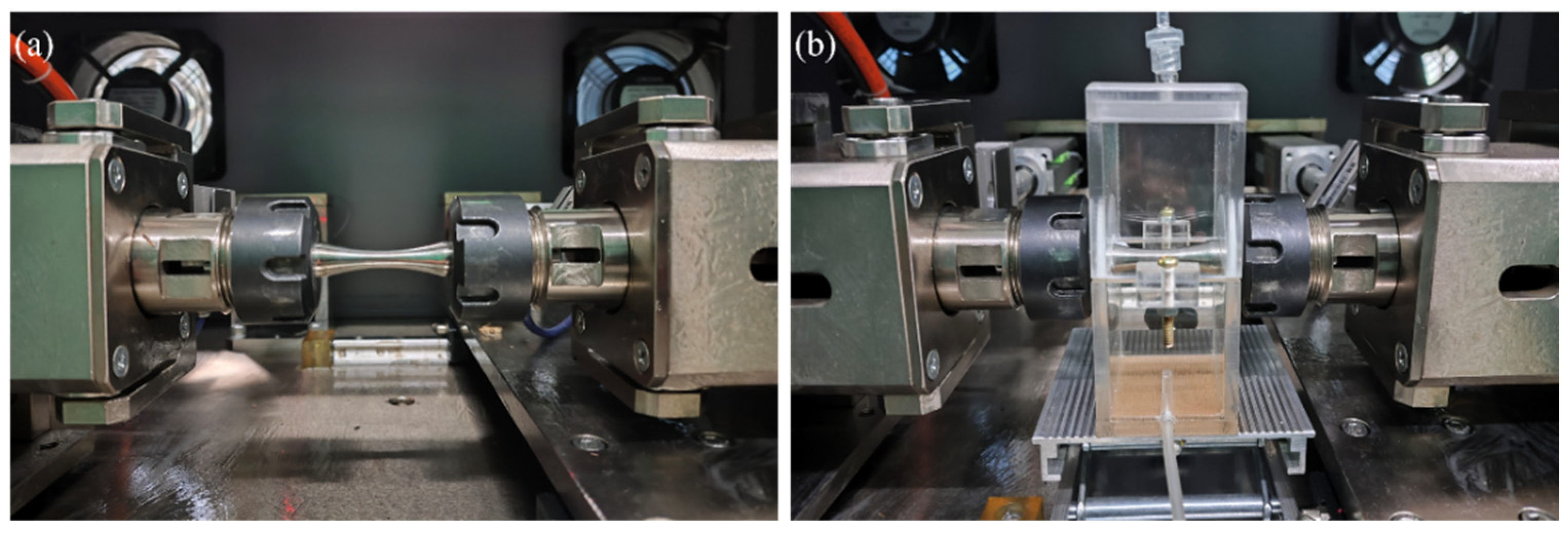
High cycle fatigue tests were carried out in corrosive media, respectively. Axles were subjected to four-point rotating bending fatigue testing in simulated corrosion solution, applying 36 Hz cyclic loading at R = −1 stress ratio. The 36 Hz load frequency applied corresponds to the equivalent loading frequency for a high-speed railway train running at 360 km/h. In the corrosion fatigue test, 3.5 wt.% NaCl solution was adopted to simulate the external corrosion environment. The environment chamber was made of transparent acrylic plate and sealed around to prevent leakage, as shown in Figure 3. During the fatigue loading process, the corrosion fluid flow rate was quantitatively regulated to 1.6 mL/min by controlling the speed of the pump. Afterwards, the fracture surface of the failed specimen was observed by the SEM (Jeol Ltd., Tokyo, Japan) to reveal the fatigue and corrosion fatigue failure mechanisms.

3. Experimental Results

3.1. Morphologies of Impact Damage

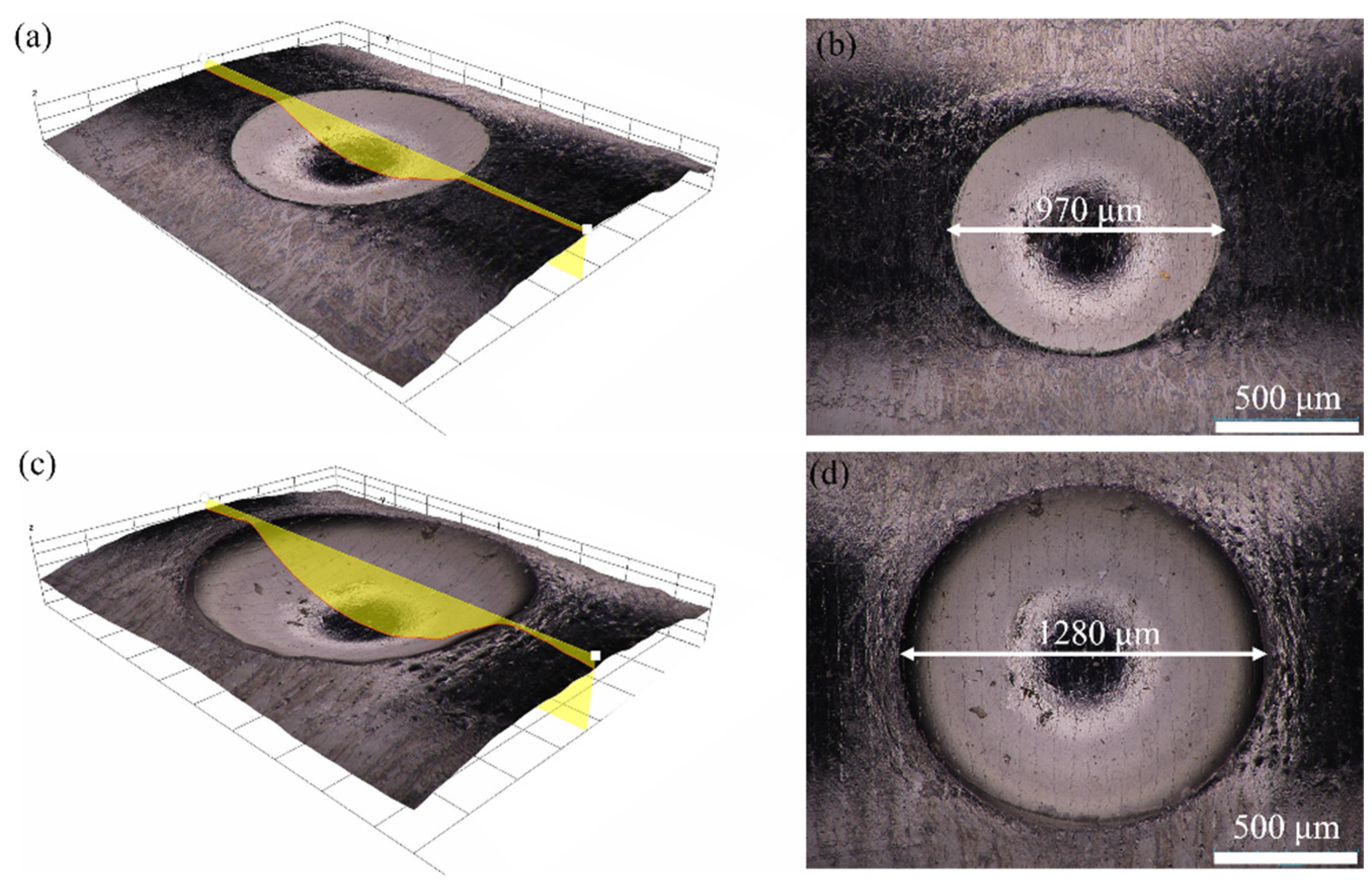
Morphologies of the two kinds of impacted semi-sphere craters are illustrated in Figure 4. Specifically, the geometrical details of the two defects, average depth d, average surface diameter 2c, and the square root of projected area √area are 110 μm, 970 μm, and 265 μm (for USRPed + FODed-v = 100 m/s), 210 μm, 1280 μm, and 580 μm (for USRPed + FODed-v = 167 m/s).
SEM was adopted to characterize the micro damage of FOD crater, as shown in Figure 5, including the global image and corresponding local magnifications of selected regions. Here, Figures (b), (c), (d), and (e) are the zoomed-in feature maps corresponding to the lettered regions in Figure (a). Materials are pushed to the edge of the crater by the projectile impact and piled up on the rim. Micro-notches and micro-cracks formed at crater rims act as preferential crack initiation sites, exacerbating stress concentration during subsequent fatigue loading.

3.2. Microstructure and Hardness

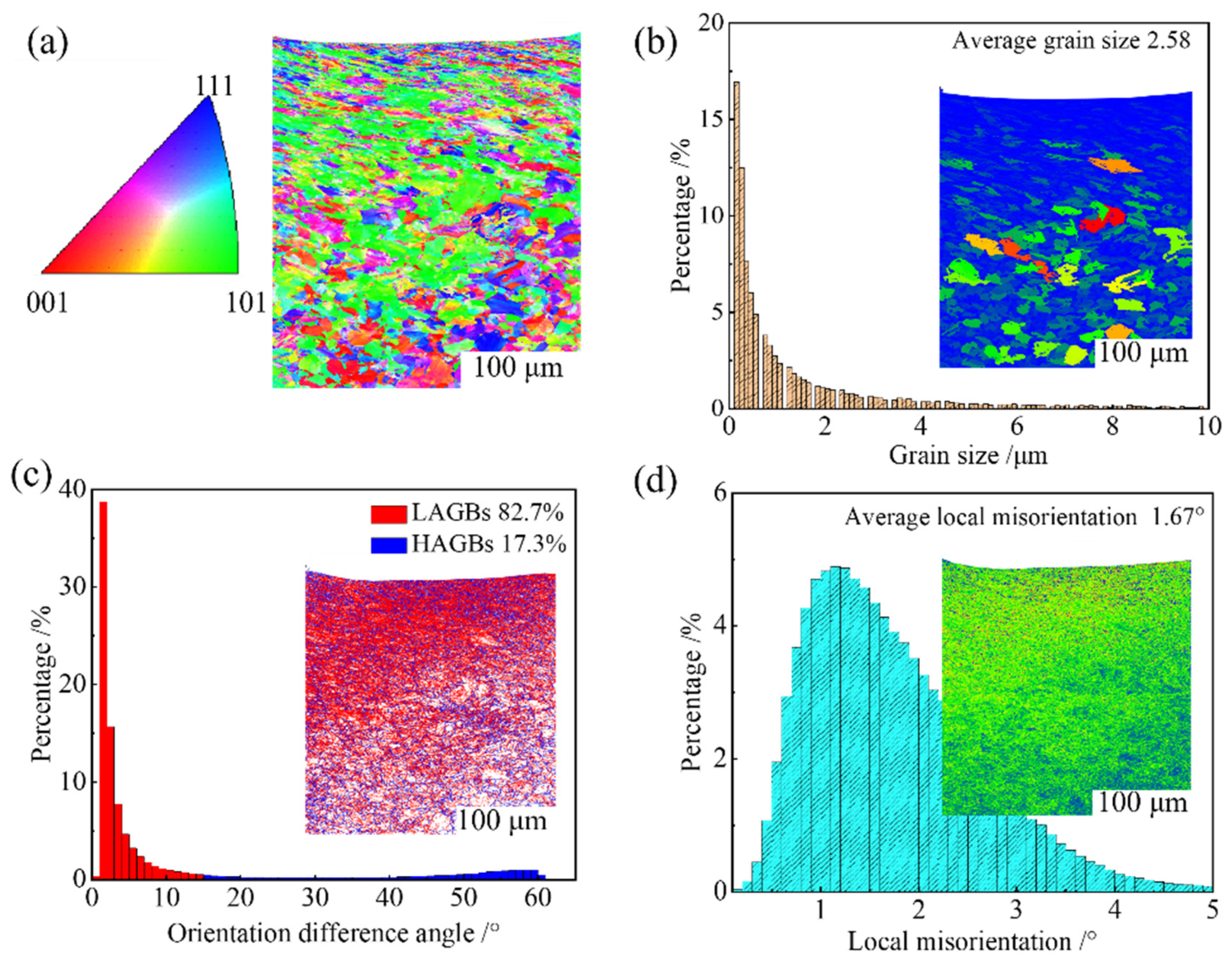
To correlate foreign object damage with electrochemical corrosion and corrosion fatigue mechanisms, EBSD analysis characterized microstructural evolution at impact crater bases (Figure 6). The previous research demonstrates that the surface grain of the EA4T axle specimen is refined from 7.0 μm of base material to 2.6 μm after the surface strengthen by USRP [18]. Foreign object impact induces severe plastic deformation at the material surface, dynamically refining grain structures through dislocation multiplication [19]. A ~450 μm thick surface plastic deformation layer is induced through the projectile impact, as shown in Figure 6a. The data in Figure 6b suggests that the high-impact velocity causes the obvious grain refinement. In the grain boundary maps, the small-angle grain boundaries (<15°) are dense on the surface of the specimen impacted by v = 100 m/s. In addition, Figure 6d display that the kernel average misorientation (KAM) value is 1.67. The KAM map qualitatively reflects the degree of plastic deformation, with higher values indicating greater severity.
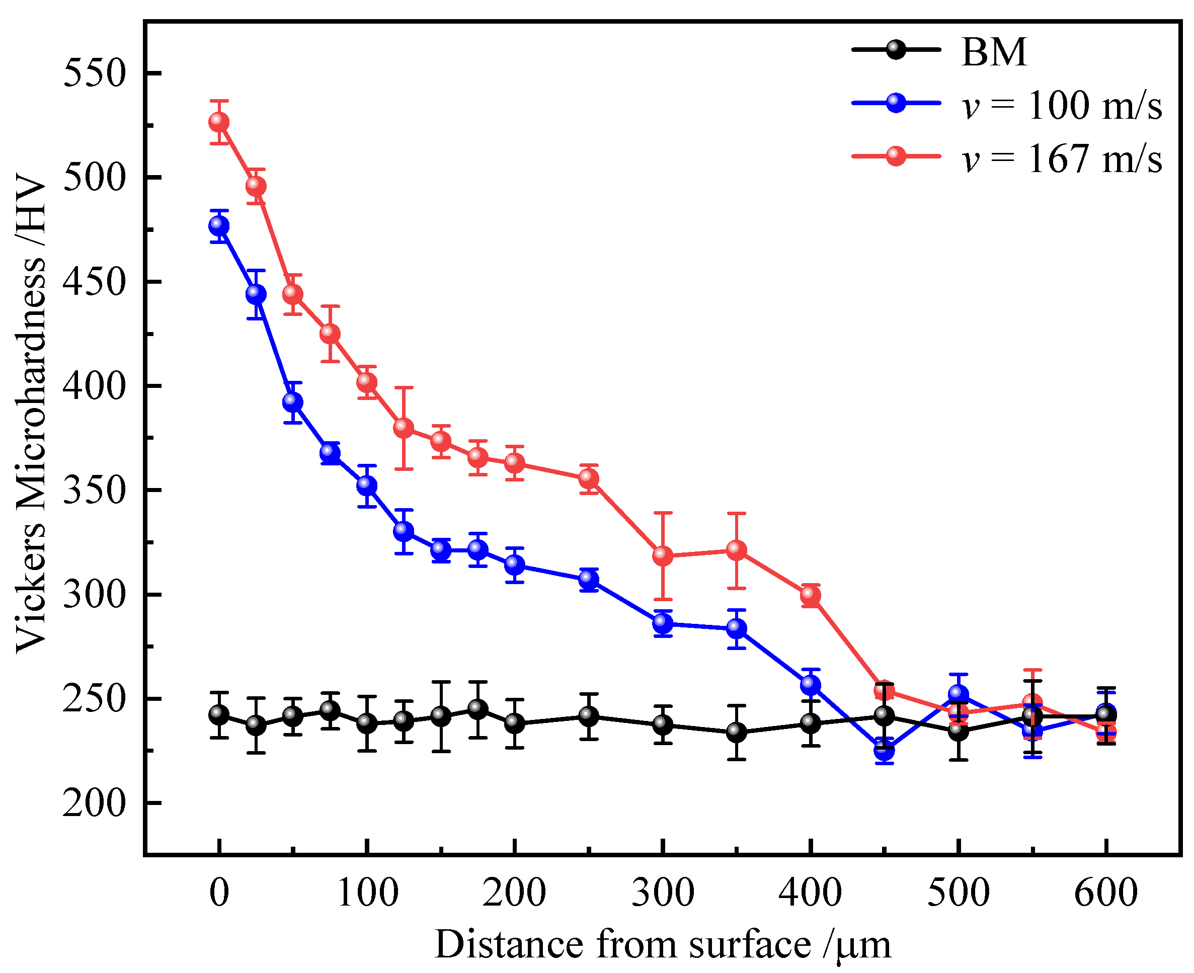
The gradient distributions of microhardness with error bars below the foreign object impacted crater are presented in Figure 7. The surface microhardness of the crater bottom reaches 526 HV (v = 167 m/s) and 476 HV (v = 100 m/s) from the initial value of 245 HV. Microhardness exhibits a gradient decline from the surface, converging to the base material value (≈245 HV) at ≈450 μm depth.
The introduction of residual stress field and grain refinement on the surface of the specimen promotes the adjustment of subsurface crystal structure and dislocation accumulation to form a harder surface layer. Due to the obstruction of the transmission of the impact force by the material organization, the impact force of effect decreases along the depth of the transmission of the material organization. Consequently, strain gradient accumulation manifests within the microstructural framework, wherein grains at distinct depth intervals experience heterogeneous deformation. This phenomenon induces depth-dependent gradients in hardness characteristics, grain size distribution, and stress–strain response throughout the material’s cross-section.

3.3. Electrochemical Corrosion Behavior

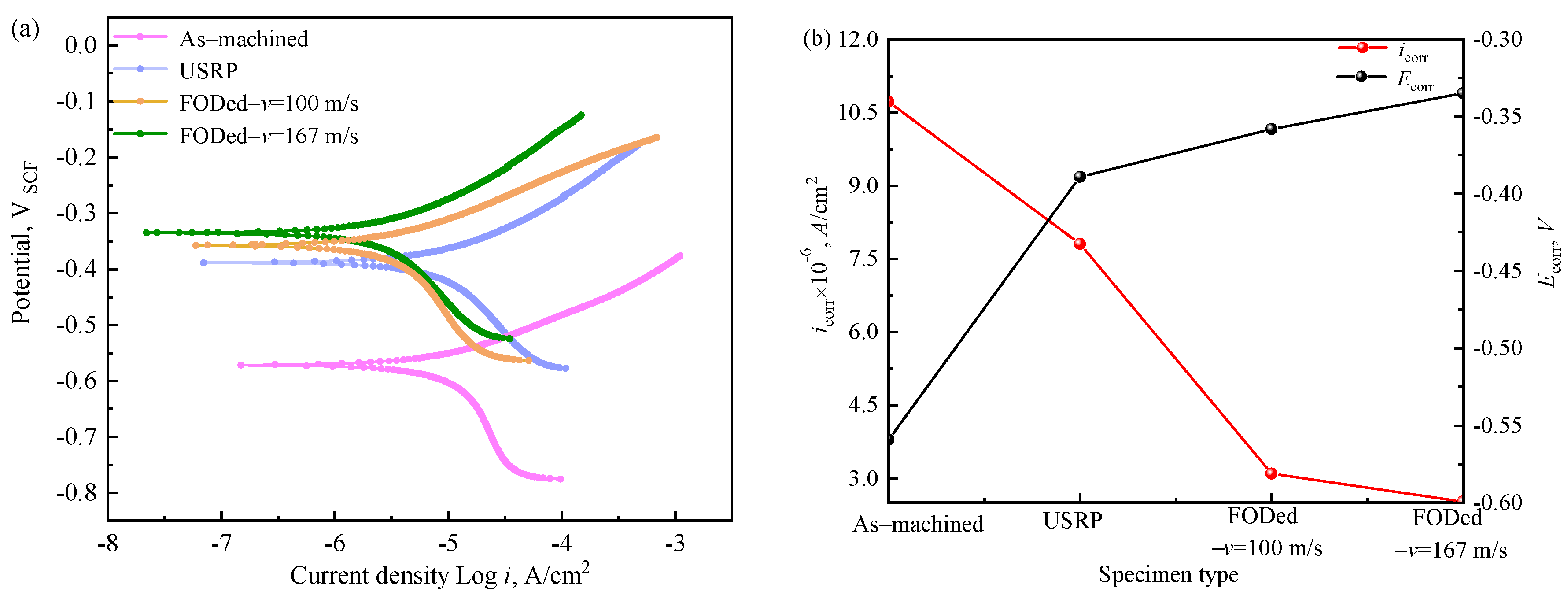
Figure 8a presents the polarization curves of diverse specimens within a 3.5% NaCl solution. The potentiodynamic polarization curves of the distinct specimens exhibit a largely consistent trend. Compared with the as-machined specimen, the corrosion potential of the axle specimen after being strengthened and impacted by foreign object shows a positive shift, and the value increases. The experimental results were calculated and analyzed by Tafel extrapolation method, and the corrosion potentials, Ecorr and current densities, icorr of various specimens were obtained, as illustrated in Figure 8b. The as-machined surface exhibited the most active corrosion potential, indicating heightened corrosion susceptibility and accelerated degradation kinetics in corrosive environments. The as-machined surface exhibits peak corrosion current density, reflecting accelerated anodic dissolution kinetics and maximum corrosion aggressivity in the test electrolyte. However, after the surface strengthening treatment and object impact, the corrosion current density value of the sample is significantly reduced, and the corrosion resistance of the sample is significantly improved, which is mainly due to the residual compressive stress-induced and surface grain refined by both the USRP and foreign object impact [20,21]. In particular, in these two kinds of damage, the larger foreign object impact velocity can better improve the corrosion resistance of the axle sample.

3.4. Corrosion Fatigue Performance

Due to the combined action of cyclic stress [22] and corrosive environments [23,24], corrosion fatigue—a mechano-electrochemical synergistic damage mechanism—can drastically compromise the service life of structural components.
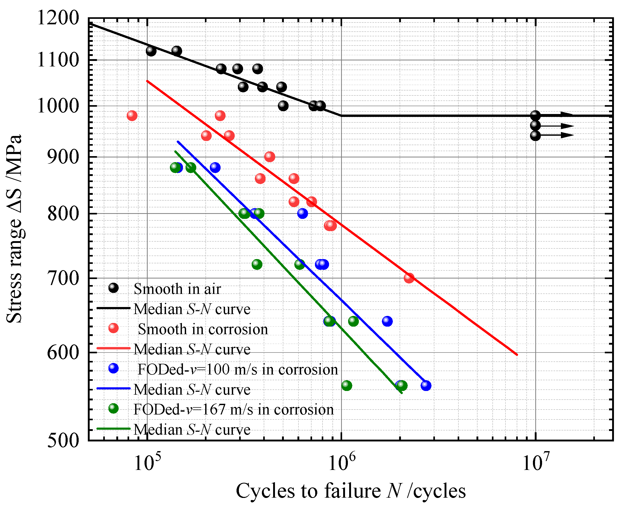
Figure 9 summarizes the influence of damage caused by foreign object impact velocities on the fatigue strength of ultrasonic rolling strengthened axle specimens in corrosive environment. Regardless of surface damage or not, the axle specimens eventually experience fatigue failure. In addition, the faster the impact velocity, the greater the surface damage of the axle specimen, and the shorter its fatigue life at the same stress level. Although an increase in the impact velocity gives rise to a higher magnitude of residual compressive stress at the base of the impact crater, it concurrently results in more significant macroscopic stress concentration and microscopic damage. Consequently, this leads to a reduction in the corrosion fatigue resistance of the axle.
Figure 10a illustrates that, in smooth-surfaced specimens subjected to immersion in an NaCl solution, multiple environmentally assisted fatigue cracks nucleate preferentially at corrosion pit sites, suggesting a critical role of localized pitting in fatigue crack initiation processes. During the incipient phase of corrosion fatigue, electrochemical activity facilitates the nucleation of corrosion pits on the material surface; these pits act as microstructural heterogeneities, serving as preferential sites for stress concentration and thereby governing the early stages of fatigue crack initiation. In addition, the Cl element detected by EDS (as displayed in Figure 10c) can pass through the surface broken oxide layer to accelerate the corrosion process (Figure 10d) [25,26].
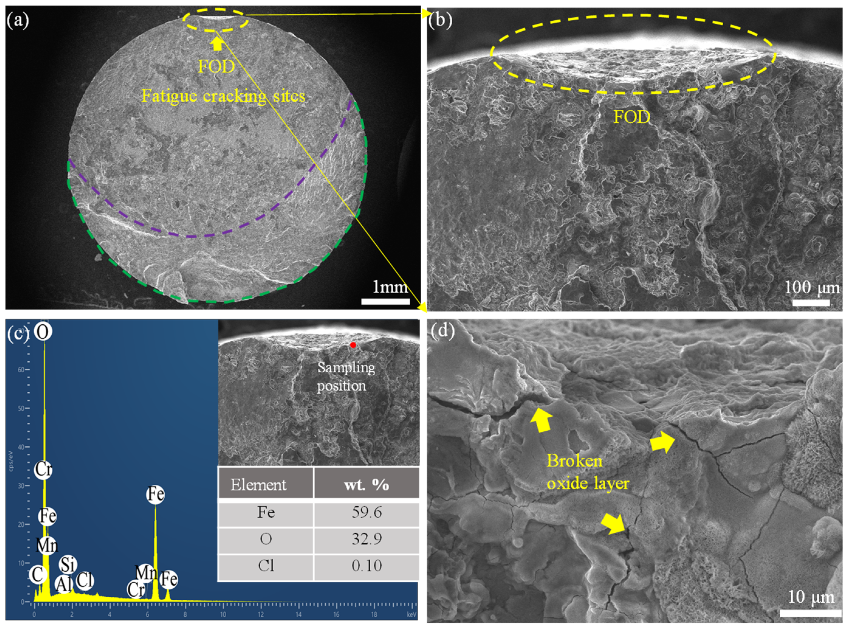
Figure 11 reveals the mechanism of the degrade in corrosion fatigue performance of damaged axle specimens compared with the smooth ones. It is evident that the surface defects are the main factor inducing the initiation of corrosion fatigue cracks. After being impacted by foreign object, the corrosion fatigue property of damaged axle specimens is affected by many factors, including stress concentration at macroscopic crater, residual stress and microscopic damage, etc. Although residual compressive stresses and grain refinement partially inhibit crack nucleation and propagation, stress concentration at defect sites, residual tensile stresses, and micro-damage synergistically create preferential nucleation sites and accelerated propagation for corrosion fatigue failure [27]. In addition, the Cl element characterized by EDS (Figure 11c) would also penetrate into the metal surface through the broken oxide layer to accelerate the corrosion fatigue failure, as shown in Figure 11d.

4. Discussion

4.1. Corrosion Electrochemical Behavior

According to the Fe and O elements quantitative analysis in Figure 10c, it is hypothesized that the formation of corrosion pits on the EA4T steel in NaCl solution includes the following electrochemical reactions [28]:
The anodic reaction:
Fe Fe 2 + + 2 e
The cathodic reaction:
O 2 + 4 e + 2 H 2 O 4 OH
2 H + + 2 e 2 H H 2
Due to the sufficient contact time with the corrosive solution, the Fe2+ and OH are able to combine in the following manner:
Fe 2 + + 2 OH Fe ( OH ) 2
4 Fe ( OH ) 2 + 2 H 2 O + O 2 4 Fe ( OH ) 3
From the above equations, it can be seen that in the anode reaction, the matrix iron loses electrons and coverts into Fe2+, while in the cathode reaction, the H2O in the corrosion solution coverts into OH, which reacts chemically with the iron ion Fe2+ in the anode to form the electrochemical corrosion product Fe(OH)2.
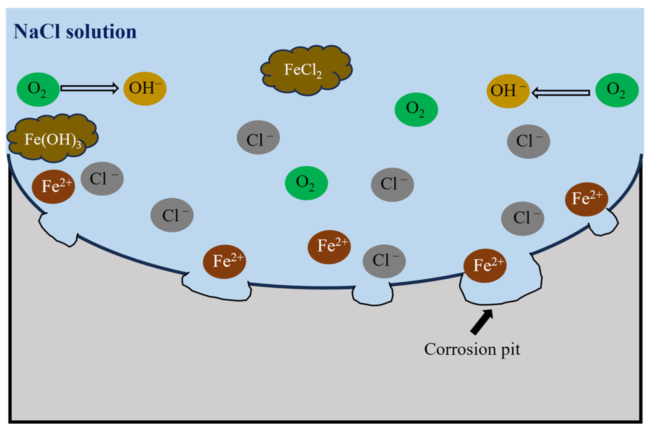
As displayed in Figure 12, with the progress of the electrochemical reaction, Cl in the NaCl solution preferentially invade the weak area of the surface to form an active corrosion site, which can induce local corrosion of surface Fe elements and further dissolve to form tiny voids [29]. As erosion time increases, these tiny voids spread outward to form larger corrosion pits. Simultaneously, corrosion products precipitate from the surface layer of the sample.
In this study, the corrosion resistance of the axle specimen surface is improved after being impacted by the foreign object; especially with the increase in impact speed, the corrosion resistance is further improved (see Figure 8). As illustrated in Figure 6, subsequent to foreign object impact, the EA4T steel specimen undergoes severe plastic deformation at the surface layer. This deformation induces pronounced grain refinement within the microstructure, accompanied by a concomitant increase in grain boundary density, consistent with dynamic recrystallization mechanisms under high-strain loading conditions. As grain boundaries can hinder the expansion of corrosion in the solution, more grain boundaries can reduce the corrosion rate of the sample [30]. On the other hand, the compressive residual stress introduced by the high-speed impact can prevent the initiation and propagation of surface cracks, thereby inhibiting the large-scale corrosion of the sample surface by the solution and effectively enhancing the corrosion resistance of the material [31]. Therefore, a higher impact velocity results in more significant grain refinement and residual compressive stress, leading to better improvement in corrosion resistance.

4.2. Corrosion Fatigue Behavior

4.2.1. Corrosion Fatigue Strength Analysis

Figure 9 demonstrates that foreign object impact velocity governs the corrosion fatigue strength of axle specimens. Specifically, as the impact speed increases, the corrosion—fatigue strength of the specimen—decreases. The defects introduced on the surface of the axle specimen by the impact of foreign object cause geometric notches and uneven distribution of residual stress. Generally, the damage degree of the defect can be expressed by the theoretical stress concentration coefficient, Kt = 1 + 2√(d/r), where d is the defect depth, and r is the defect radius that is equivalent to the radius of the foreign object [27,32]. In addition, according to the Peterson’s formula [33], the fatigue notch coefficient Kf can be expressed as Kf = 1 + (Kt−1)/(1 + a*/r), where a* is the material constant. Hence, with the increase in defect depth d, the stress concentration coefficient Kt and fatigue notch coefficient Kf increase, the damage of the axle specimen increases, and the corrosion fatigue strength decreases.

4.2.2. Defect Tolerance Evaluation

Due to the corrosive service conditions formed by the humid atmospheric environment, the corrosion phenomenon occurs on the surface of the axle structure, accelerating the fatigue damage and failure of the axle subjected to foreign object [34]. Hence, it is necessary to explore the functional relationship between the size of key defects and fatigue strength in corrosive environments and establish an evaluation model for the service performance of foreign object-damaged axles considering environmental effects.
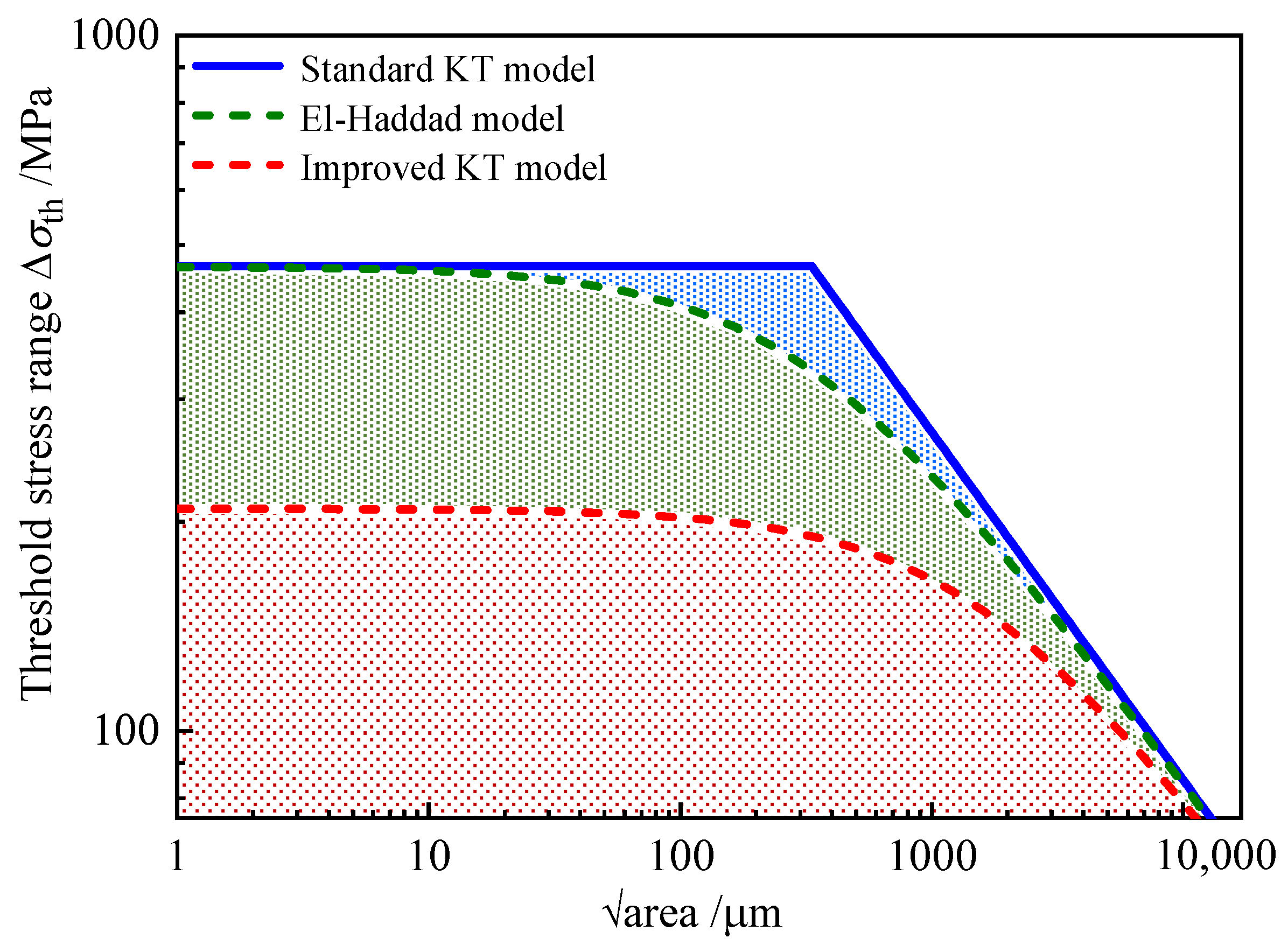
The classical KT diagram establishes fundamental correlations between fatigue limits and crack growth thresholds, unifying nominal stress-based design and damage tolerance methodologies to enable reliable defect assessment in engineering structures [35,36]. Typically, the horizontal axis of the KT diagram denotes the fatigue limit of the smooth specimen, while the diagonal line represents the threshold stress range, Δσth:
Δ σ th = Δ K th , L Y π a r e a
where √area represents the Murakami parameter, which is defined as the square root of the projected area of the impact crater perpendicular to the loading direction. Here, Y denotes the geometric factor (assigned a value of 0.65 for surface defects). ΔKth,L is the long crack propagation thresholds, according to our previous study, ΔKth,L = 9.8 MPa⸱√m for the USRPed EA4T specimen in corrosion environment [18].
By introducing a fictitious intrinsic defect parameters through the El-Haddad model [37], a smooth transition curve between the fatigue limit and crack propagation threshold can be obtained. This fictitious intrinsic defect parameters can be expressed as
a r e a 0 = 1 π Δ K th ,   L Y Δ σ 0 2
Then, the El-Haddad-modified KT model is calculated by
Δ σ th = Δ K th , L Y π ( a r e a + a r e a 0 )
As illustrated in Figure 9, with the decrease in stress level, the influence of corrosion environment on the fatigue strength of the smooth specimens increases. Even at the stress of 700 MPa, which is far below the fatigue limit in the atmospheric environment, corrosion fatigue failure still occurs.
In fatigue life reliability research, when fatigue life is treated as a random variable, it exhibits a stable probability density distribution under specified stress level conditions. This distribution constitutes an inherent property, characterizing the stable frequency properties at the value points of the random variable. Probability density distributions of random variables can be categorized into two types: normal distribution and skewed distribution. Fatigue life, as a random variable, follows a skewed Weibull distribution. If a logarithmic transformation is applied to fatigue life—that is, if logarithmic fatigue life (log-fatigue life) is treated as the random variable—the resulting distribution conforms to a normal distribution.
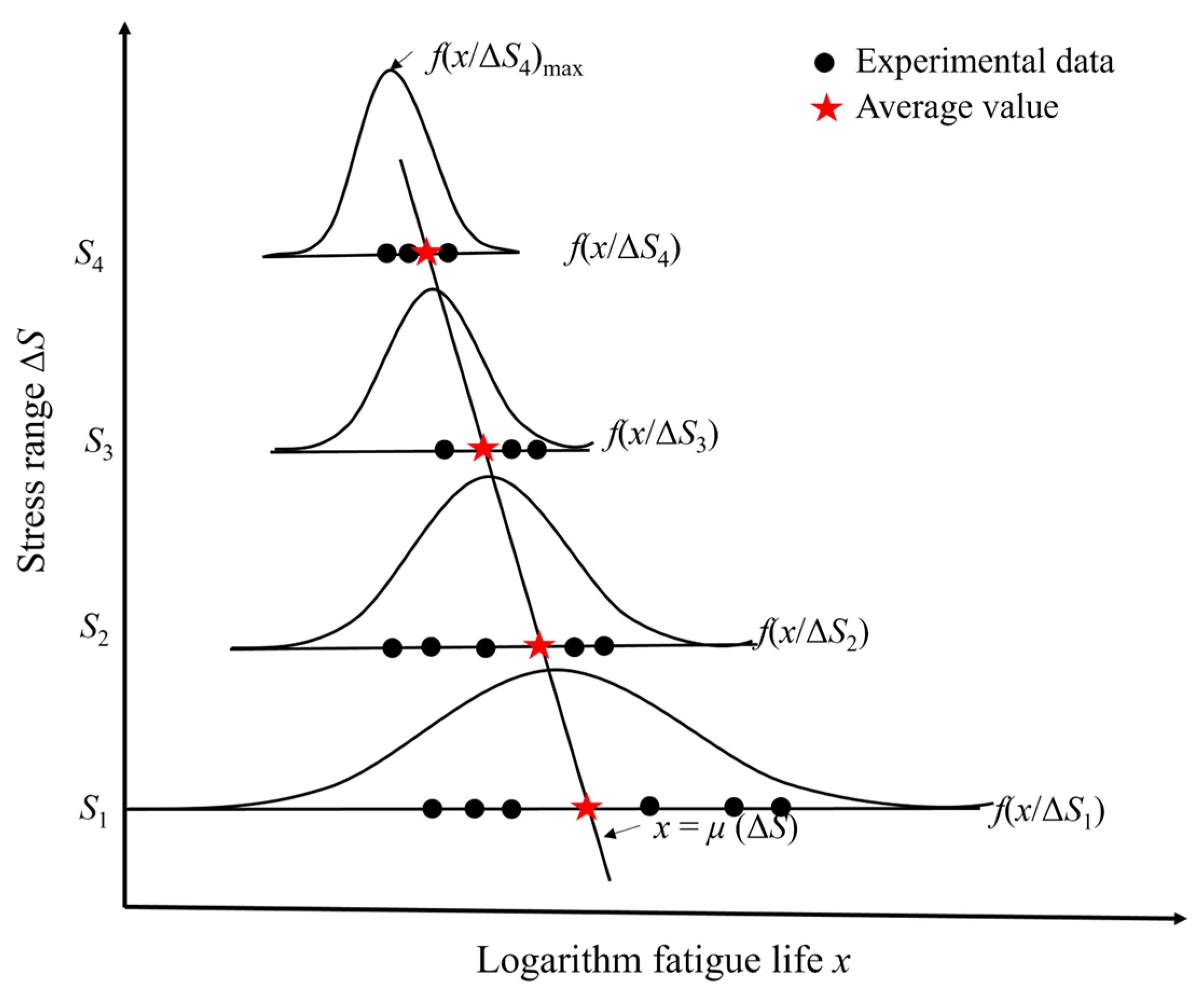
In fatigue life reliability analysis, the obtained probability density function with logarithmic fatigue life as the random variable is, in essence, a conditional probability density function (CPDF)—specifically, the probability density distribution function under specified stress level conditions, as shown in Figure 13. The data points in this figure represent the distribution of fatigue life at a specified stress level [38]. In view of the dispersion of corrosion fatigue life, the CPDF was used to analyze the corrosion fatigue properties of axle steel [14]. Therefore, the CPDF method was employed to determine the fatigue limit of the smooth axle specimen under corrosive environmental conditions.
As indicated by the CPDF, the conditional probability density distribution curve generates a conditional probability density function surface under varying stress levels. This surface facilitates the characterization of the probability density distribution for logarithmic fatigue life (x), treated as a random variable, at each distinct stress level ΔS within a three-dimensional coordinate system [38]:
y x = f x ( x / Δ S ) = 1 σ ( Δ S ) 2 π exp x μ ( Δ S ) 2 2 σ 2 ( Δ S )
Within this framework, x denotes the logarithmic fatigue life, defined as x = log (Nf), where Nf represents the number of cycles to failure. The variable ΔS corresponds to the applied stress, while μS) and σS) denote the mean value and standard deviation of x conditioned on the stress level ΔS. The term yx quantifies the probability density of the logarithmic fatigue life (x) at each respective stress level ΔS.
According to the Basquin equation and empirical reciprocal model, the relationship between μS), σ(ΔS), and ΔS in Table 2 can be expressed as
μ ( Δ S ) = x 50 = log ( N 50 ) = log ( C ) m log ( Δ S )
σ ( Δ S ) = ( a + b Δ S ) 1
where C, m, a and b are the fitting parameter, in this study, log(C) = 28.37, m = 7.734, a = −13.696, b = 0.0294.
By substituting Equations (10) and (11) into Equation (9), the CPDF of the logarithmic fatigue life of the smooth specimen as a function of stress level can be obtained as
y x = f x ( x / Δ S ) = 0.0294 Δ S 13.696 2 π exp x + 7.734 l o g ( Δ S ) 28.370 2 ( 0.0294 Δ S 13.696 ) 2 2
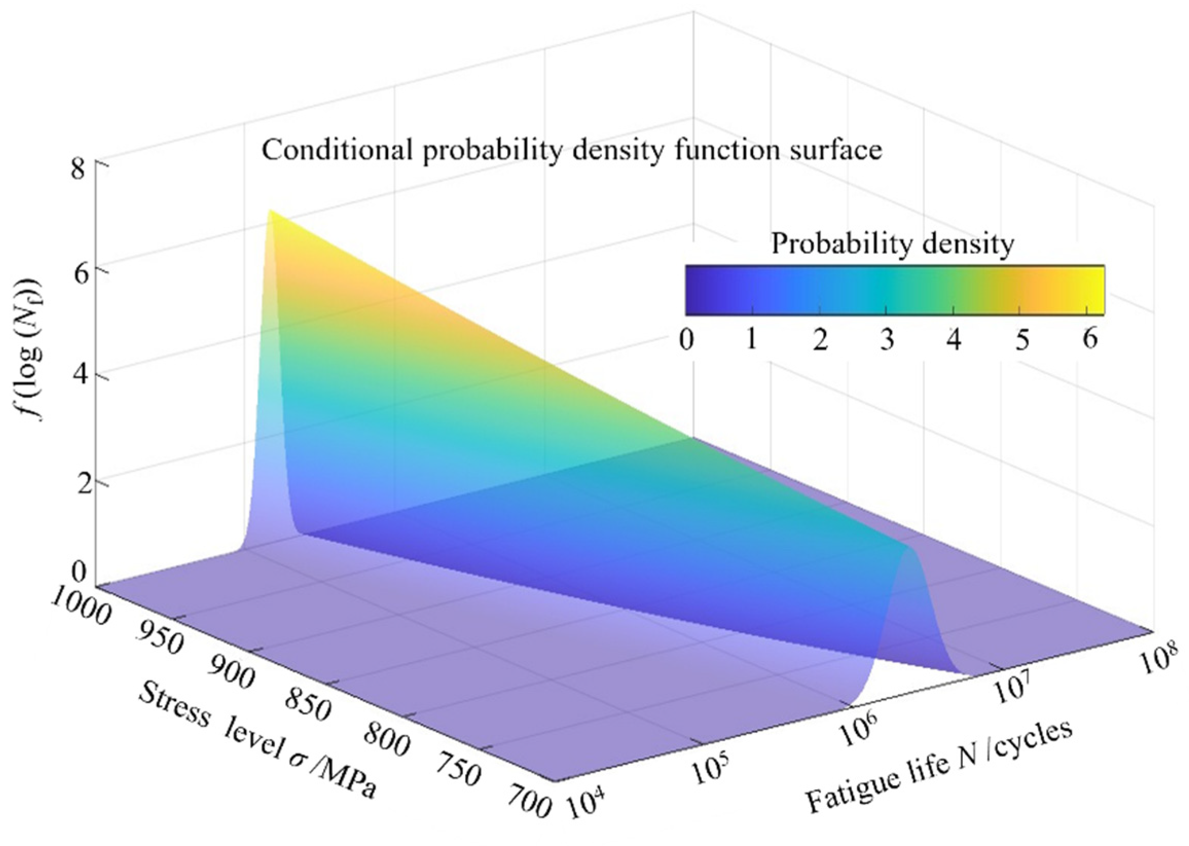
Figure 14 illustrates the conditional probability density function surface for the corroded smooth axle specimen, which captures the dynamic evolution of the probability density distribution of fatigue life (x)—treated as a random variable—across varying stress levels (ΔS).
Evidently, the peak value of the conditional probability density curve can be mathematically represented as follows:
y max = f x ( x / Δ S ) max = 1 σ ( Δ S ) 2 π
Due to the fact that the fatigue limit is the amplitude of cyclic stress applied to a material that does not experience failure, it can be considered that the failure phenomenon of components under the fatigue limit is a small probability event [33,38]. Empirical studies indicate that for a probability distribution f(x), as the maximum value of its conditional probability density function f(xSa)max approaches zero (f(xSa)max → 0), the likelihood of the even x occurring within any finite interval diminishes to zero. Such an event is termed a small probability event in probabilistic terms. Therefore, the stress amplitude at σ(ΔS) →∞ can be considered as the theoretical fatigue limit Δσ0. Based on Equation (13), the corrosion fatigue limit of USRP EA4T axle smooth specimen is 466 MPa.
As the axle is an important safety critical component of high-speed EMU, the fatigue limit of FODed-v = 167 m/s specimen is used to evaluate the service performance of the axle considering the operational safety [5]. The CPDF of the FODed-v = 167 m/s specimen can be obtained by the data in Table 3 as
y x = f x ( x / Δ S ) = 0.0206 Δ S 5.547 2 π exp x + 5.358 l o g ( Δ S ) 21.001 2 ( 0.0206 Δ S 5.547 ) 2 2
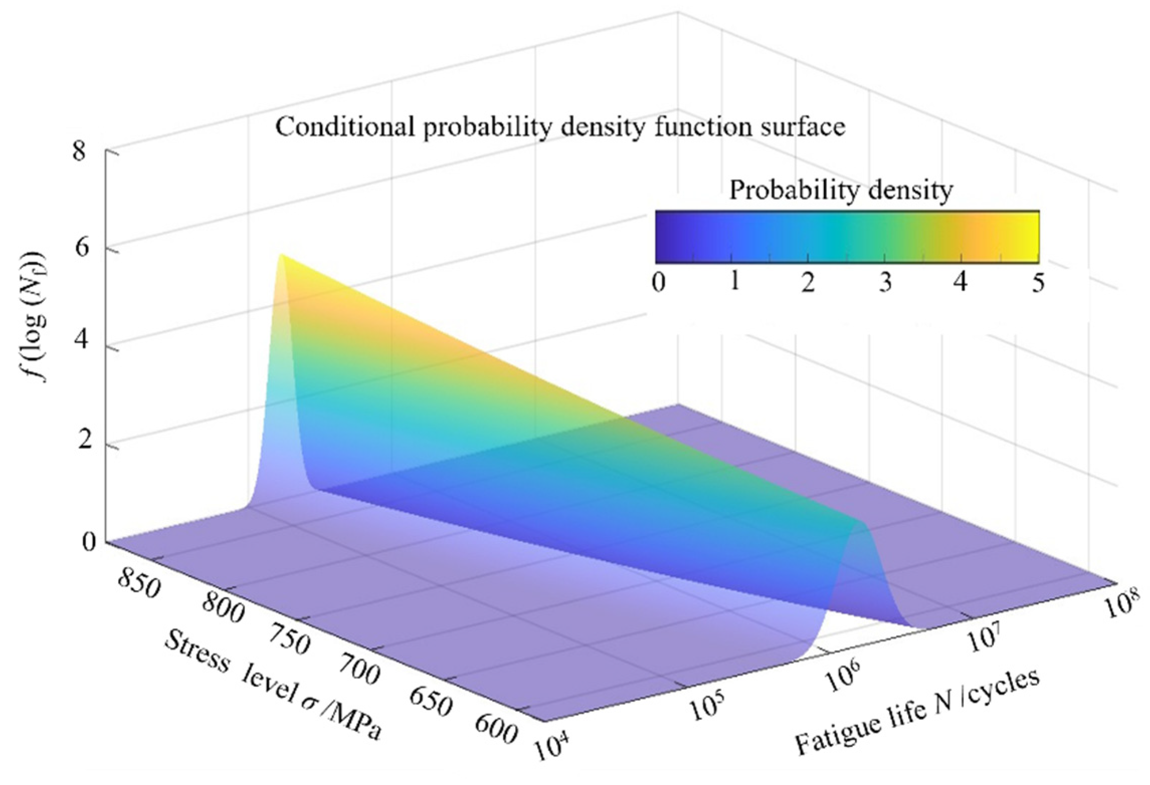
Figure 15 displayed the conditional probability density function surface of FODed-v = 167 m/s axle specimen in corrosion. Hence, based on Equation (14), the corrosion fatigue limit of FODed-v = 167 m/s specimen is 270 MPa.
The above fatigue limit is obtained from the fatigue test data of small-size specimens, which does not take into account the differences between actual engineering structures and laboratory specimens. Hence, through the application of size effect correction factors, the fatigue limit of small-scale specimens is extrapolated to determine the fatigue limit of full-sized damaged axles under service conditions [39]:
Δ σ 0 a = Δ σ 0 s α β ε
where Δα0a is the fatigue limit of full-scale railway axle, Δα0s is the fatigue limit of FODed-v = 167 m/s axle specimen, α, β, and ε are the coefficient of load factor, surface roughness and size effect, respectively. In this study, α = 1.0, β = 0.9, ε = 0.86 [5]. Then, the fatigue limit of the foreign object damaged full-scale EA4T axle in corrosion solution is 210 MPa.
As Figure 16 demonstrates, the blue and green lines in Figure 16 are the standard KT diagram and El-Haddad-modified KT diagram of EA4T axle specimen in corrosion environment based on the theoretical fatigue limit of 466 MPa. Compared with the standard KT diagram based on the smooth specimen fatigue limit, the improved KT diagram takes the full-scale axle fatigue limit subjected to FOD as the horizontal line, and fully considers the differences in geometric dimensions, surface quality, and loading methods between the specimen and the full-scale axle, as well as the adverse effects of surface damage on the component fatigue performance, thus obtaining a more reasonable and reliable fatigue loading safety zone.
Currently, axle structural design, strength verification, and service evaluation are conducted using the nominal stress method. To ensure operational safety and reliability, the adoption of larger safety factors often leads to either excessive or under-maintenance, resulting in immediate scrapping whenever defects exceed allowable standards. However, various defects inevitably emerge during the manufacturing and operation of axles. To address this, the constructed modified KT diagram for full-size axles, which integrates the nominal stress method and damage tolerance approach, can effectively correlate the fatigue limit with defect characteristics based on fracture mechanics. It establishes a semi-quantitative functional relationship between the residual structural strength of the axle and the defect size, and this functional relationship enables the prediction of the maximum allowable defect size for axles in service. Furthermore, according to this KT diagram, it can be determined that when the allowable stress level is sufficiently low, fatigue crack propagation and failure phenomena generally do not readily occur in axle structures even with defects of certain sizes. Additionally, when sufficiently small defects exist in the structure, their impact on fatigue strength and remaining service life can be considered negligible.

5. Conclusions

This study examines the effects of surface damage and corrosive environmental conditions on the fatigue performance of EA4T steel axles employed in high-speed railway applications. Additionally, it elucidates the mechanistic role of foreign object intrusion in influencing corrosion electrochemical behavior within these operational contexts. A corrosion fatigue strength evaluation model for axles with surface damage was developed through the integration of the El-Haddad model and size effect theory. The primary findings derived from this research are as follows:
(1)
Impact-induced surface hardening improves the corrosion resistance of EA4T steel, with higher impact speeds enhancing this effect. At 167 m/s, Ecorr increased by 13.88% and icorr decreased by 67.61% versus the smooth sample.
(2)
Corrosion fatigue strength decreased progressively with increasing defect size (√area: 265–580 μm). At the maximum defect size (√area = 580 μm, v = 167 m/s), the theoretical fatigue limit reached 270 MPa.
(3)
Environmentally induced cracks in smooth specimens preferentially initiated at localized corrosion pits. However, surface defects emerged as the primary determinant governing the initiation of corrosion fatigue cracks in foreign object damaged axle specimens.
(4)
In contrast to the conventional KT diagram derived from the fatigue limit of smooth specimens, the refined KT diagram integrating considerations of size effect and surface damage becomes smaller, thereby enabling the determination of operational safety boundaries for fatigue loading with enhanced reliability and accuracy.
This study investigates the failure mechanisms and residual strength assessment methods for damaged axles in corrosive environments. However, given China’s vast geographical expanse and diverse environmental conditions, axles will inevitably operate under increasingly complex service scenarios. Consequently, future research must prioritize the service performance of axles under multifactorial conditions, encompassing studies on individual or coupled variables such as corrosion, low-temperature exposure, foreign object damage, and thermal cycling.

Author Contributions

Writing—Original Draft, Y.L.; writing—review & editing, Y.L.; methodology, Y.L. and G.L.; investigation, Y.L., G.L. and Y.H.; funding acquisition, Y.L.; data curation, C.L.; formal analysis, C.L. and C.Q.; validation, C.L., Y.H., C.Q. and P.Y. All authors have read and agreed to the published version of the manuscript.

Funding

Sincere thanks are given to the final support from the National Natural Science Foundation of China (No. 52405147) and the Natural Science Foundation of Sichuan Province (No.2023NSFSC0864).

Institutional Review Board Statement

Not applicable.

Informed Consent Statement

Not applicable.

Data Availability Statement

Data will be made available on request.

Conflicts of Interest

Author Gang Li was employed by the company Sichuan Zichen Technology Co., Ltd. Author Cunhai Li was employed by the company Sichuan Aerospace Zhongtian Power Equipment Co., Ltd. The remaining authors declare that the research was conducted in the absence of any commercial or financial relationships that could be construed as a potential conflict of interest.

References

  1. Zerbst, U.; Beretta, S.; Köhler, G.; Lawton, A.; Vormwald, M.; Beier, H.T.; Klinger, C.; Černý, I.; Rudlin, J.; Heckel, T.; et al. Safe life and damage tolerance aspects of railway axles—A review. Eng. Fract. Mech. 2013, 98, 214–271. [Google Scholar] [CrossRef]
  2. Wu, S.C.; Zhang, S.Q.; Xu, Z.W.; Kang, G.Z.; Cai, L.X. Cyclic plastic strain based damage tolerance for railway axles in China. Int. J. Fatigue 2016, 93, 64–70. [Google Scholar] [CrossRef]
  3. Klinger, C.; Bettge, D. Axle fracture of an ICE3 high speed train. Eng. Fail. Anal. 2013, 35, 66–81. [Google Scholar] [CrossRef]
  4. Zhao, H.; Han, R.P.; Gao, J.W.; Zhu, S.P.; Han, J. Fatigue performance evaluation of high-strength railway axles subjected to different surface defects. Alex. Eng. J. 2025, 127, 66–74. [Google Scholar] [CrossRef]
  5. Wu, S.C.; Xu, Z.W.; Kang, G.Z.; He, W.F. Probabilistic fatigue assessment for high-speed railway axles due to foreign object damages. Int. J. Fatigue 2018, 117, 90–100. [Google Scholar] [CrossRef]
  6. Luo, Y.; Wang, H.; Li, C.H.; Ren, X.Y.; Wu, S.C. Fatigue strength assessment of high-speed railway axle EA4T steel with foreign object damage. Eng. Fail. Anal. 2022, 133, 205961. [Google Scholar] [CrossRef]
  7. Beretta, S.; Carboni, M.; Fiore, G.; Conte, A.L. Corrosion-fatigue of A1N railway axle steel exposed to rainwater. Int. J. Fatigue 2010, 32, 952–961. [Google Scholar] [CrossRef]
  8. Gao, J.W.; Dai, G.Z.; Li, Q.Z.; Zhang, M.N.; Zhu, S.P.; Correia, J.A.F.O.; Lesiuk, G.; Jesus, A.M.P.D. Fatigue assessment of EA4T railway axles under artificial surface damage. Int. J. Fatigue 2021, 146, 106157. [Google Scholar] [CrossRef]
  9. Gao, J.W.; Yu, M.H.; Liao, D.; Zhu, S.P.; Han, J.; Lesiuk, G.; Correia, J.A.F.O.; Jesus, A.M.P.D. Fatigue and damage tolerance assessment of induction hardened S38C axles under different foreign object. Int. J. Fatigue 2021, 149, 106276. [Google Scholar] [CrossRef]
  10. Ao, N.; Zhang, H.; Xu, H.H.; Wu, S.C.; Liu, D.; Xu, P.G.; Su, Y.H.; Kan, Q.H.; Kang, G.Z. Corrosion fatigue crack growth behavior of a structurally gradient steel for high-speed railway axles. Eng. Fract. Mech. 2023, 281, 109166. [Google Scholar] [CrossRef]
  11. Li, H.; Zhang, J.W.; Ao, N.; Xu, J.S.; Ji, D.D. Influence of residual stress and its relaxation on the corrosion bending fatigue resistance of EA4T axle steel treated by ultrasonic surface rolling. Int. J. Fatigue 2023, 170, 107561. [Google Scholar] [CrossRef]
  12. Beretta, S.; Conte, A.L.; Rudin, J.; Panggabean, D. From atmospheric corrosive attack to crack propagation for A1N railway axles steel under fatigue: Damage process and detection. Eng. Fail. Anal. 2015, 47, 252–264. [Google Scholar] [CrossRef]
  13. Zhang, T.L.; Liu, Z.Y.; Du, C.W.; Liu, C.; Xu, X.X.; Li, X.G. Modeling for corrosion fatigue crack initiation life based on corrosion kinetics and equivalent initial flaw size theory. Corros. Sci. 2018, 142, 277–283. [Google Scholar] [CrossRef]
  14. Hu, Y.N.; Wu, S.C.; Withers, P.J.; Cao, H.T.; Chen, P.; Zhang, Y.J.; Shen, Z.; Vojtek, T.; Hutař, P. Corrosion fatigue lifetime assessment of high-speed railway axle EA4T steel with artificial scratch. Eng. Fract. Mech. 2021, 245, 107588. [Google Scholar] [CrossRef]
  15. Gao, J.W.; Dai, X.; Zhu, S.P.; Zhao, J.W.; Correia, J.A.F.O.; Wang, Q.Y. Failure causes and hardening techniques of railway axles-a review from the perspective of structural integrity. Eng. Fail. Anal. 2022, 141, 106656. [Google Scholar] [CrossRef]
  16. Wang, T.; Wang, T.P.; Liu, G. Investigations on the nanocrystallzation of 40Cr using ultrasonic surface rolling processing. Appl. Surf. Sci. 2008, 255, 1824–1829. [Google Scholar]
  17. Qin, T.Y.; Ao, N.; Ren, X.Y.; Zhao, X.; Wu, S.C. Determination of optimal ultrasonic surface rolling parameters to enhance the fatigue strength of railway axle EA4T steel. Eng. Fract. Mech. 2022, 275, 108831. [Google Scholar] [CrossRef]
  18. Luo, Y.; Li, G.; Ao, N.; Qi, C.; Wu, Y.; Zhang, G.; Wu, S. Effect of ultrasonic rolled material layer on the corrosion fatigue resistance of railway axle EA4T alloy steel. Eng. Fail. Anal. 2024, 157, 107895. [Google Scholar] [CrossRef]
  19. Sun, Z.; Retraint, D.; Baudin, T.; Helbert, A.L.; Brissset, F.; Chemkhi, M.; Zhou, J.; Kanouté, P. Experimental study of microstructure changes due to low cycle fatigue of a steel nanocrystallised by surface mechanical attrition treatment. Mater. Charact. 2017, 124, 117–121. [Google Scholar] [CrossRef]
  20. Sun, Q.; Yang, M.; Jiang, Y.; Lei, L.; Zhang, Y. Achieving excellent corrosion resistance properties of 7075 Al alloy via ultrasonic surface rolling treatment. J. Alloys Compd. 2022, 911, 165009. [Google Scholar] [CrossRef]
  21. Zhu, L.; Hu, X.T.; Jiang, R.; Song, Y.D.; Qu, S.D. Experimental investigation of small fatigue crack growth due to foreign object damage in titanium alloy TC4. Mater. Sci. Eng. A 2019, 739, 214–224. [Google Scholar] [CrossRef]
  22. Gok, A.; Inal, S.; Taspinar, F.; Gulbandilar, E.; Gok, K. Fatigue behaviors of different materials for schanz screws in femoral fracture model using finite element analysis. Optoelectron. Adv. Mat. 2014, 8, 576–580. [Google Scholar]
  23. Gok, K.; Ada, H.D.; Erdem, M.; Gök, A.; Topçuoğlu, K.; Alkan, M.A. Investigation of erosion corrosion caused by drinking water in the faucet with computational fluid dynamics. J. Met. Mater. Res. 2023, 6, 576–580. [Google Scholar] [CrossRef]
  24. Gok, K.; Ada, H.D.; Kilicaslan, N.; Gok, A. A review of CFD modeling of erosion-induced corrosion formation in water jets using FEA. J. Mech. Mater. Mech. Res. 2023, 6, 14–22. [Google Scholar] [CrossRef]
  25. Cerit, M.; Genel, K.; Eksi, S. Numerical investigation on stress concentration of corrosion pit. Eng. Fail. Anal. 2009, 16, 2467–2472. [Google Scholar] [CrossRef]
  26. Chen, Y.J.; Liu, C.C.; Zhou, J.; Wang, X.C. Multiaxial fatigue behaviors of 2024-T4 aluminum alloy under different corrosion conditions. Int. J. Fatigue 2017, 98, 269–278. [Google Scholar] [CrossRef]
  27. Ruschau, J.; Thompson, S.R.; Nicholas, T. High cycle fatigue limit stresses for airfoils subjected to foreign object damage. Int. J. Fatigue 2003, 25, 955–962. [Google Scholar] [CrossRef]
  28. Zhao, T.L.; Liu, Z.Y.; Du, C.W.; Dai, C.D.; Li, X.G.; Zhang, B.W. Corrosion fatigue crack initiation and initial propagation mechanism of E690 steel in simulated seawater. Mat. Sci. Eng. A 2017, 708, 181–192. [Google Scholar] [CrossRef]
  29. Luo, K.Y.; Wang, C.Y.; Cui, C.Y.; Lu, J.Z.; Lu, Y.F. Effect of coverage layer on the electrochemical corrosion behaviour of Mg-Al-Mn alloy subjected to massive laser shock peening treatment. J. Alloys Compd. 2019, 782, 1058–1075. [Google Scholar] [CrossRef]
  30. Xu, X.X.; Liu, Z.Y.; Zhao, T.L.; Cui, Q.Q.; Zhang, T.Y.; Li, X.G. Corrosion fatigue behavior of Fe-16Mn-0.6C-1.68Al twinning-induced plasticity steel in simulated seawater. Corros. Sci. 2021, 182, 109282. [Google Scholar] [CrossRef]
  31. Pu, Z.; Song, G.L.; Yang, S.; Outeiro, J.C.; Dillon, O.W., Jr.; Puleo, D.A.; Jawahir, I.S. Grain refined and basal textured surface produced by burnishing for improved corrosion performance of AZ31B Mg alloy. Corros. Sci. 2012, 57, 192–201. [Google Scholar] [CrossRef]
  32. Luo, S.H.; Nie, X.F.; Zhou, L.C.; Li, Y.; He, W. High cycle fatigue performance in laser shock peened TC4 Titanium alloys subjected to foreign object damage. J. Mater. Eng. Perform. 2018, 27, 1466–1474. [Google Scholar] [CrossRef]
  33. Schiijve, J. Fatigue of Structures and Materials; Springer: Berlin/Heidelberg, Germany, 2009; pp. 171–180. [Google Scholar]
  34. Li, H.; Zhang, J.W.; Wu, S.C.; Zhang, H.O.; Fu, Y.N. Corrosion fatigue mechanism and life prediction of railway axle EA4T steel exposed to artificial rainwater. Eng. Fail. Anal. 2022, 138, 106319. [Google Scholar] [CrossRef]
  35. Murakami, Y. Metal Fatigue: Effects of Small Defects and Nonmetallic Inclusions; Elsevier: Amsterdam, The Netherlands, 2002. [Google Scholar]
  36. Peters, J.O.; Boyce, B.L.; Chen, X.; McNaney, J.M.; Hutchinson, J.W.; Ritchie, R.O. On the application of the Kitagawa-Takahashi diagram to foreign-object damage and high-cycle fatigue. Eng. Fract. Mech. 2002, 69, 1425–1466. [Google Scholar] [CrossRef]
  37. El-Haddad, M.H.; Topper, T.H.; Smith, K.N. Prediction of non-propagation cracks. Eng. Fract. Mech. 1979, 11, 573–584. [Google Scholar] [CrossRef]
  38. Zhai, J.M.; Li, X.Y. A methodology to determine a conditional probability density distribution surface from S-N data. Int. J. Fatigue 2012, 44, 107–115. [Google Scholar] [CrossRef]
  39. Lee, Y.L.; Pan, J.; Hathaway, R.B.; Barkey, M.E. Fatigue Testing and Analysis: Theory and Practice; Elsevier: Burlington, VT, USA, 2005. [Google Scholar]
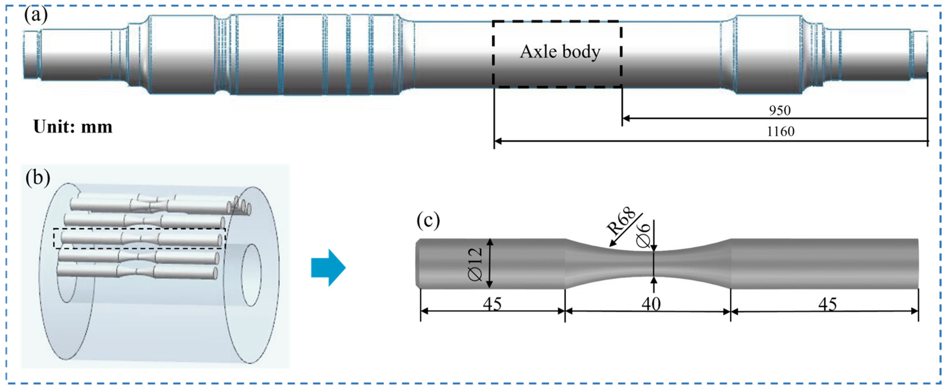
Figure 1. Sampling locations and dimensions of the HCF specimens: (a,b) sampling location from the EA4T axle; (c) dimensions of the rotating bending fatigue specimen.
Technologies 13 00368 g001
Figure 2. Photograph of the compressed gas gun facility.
Technologies 13 00368 g002
Figure 3. The real images of HCF tests: (a) in air; (b) in corrosive medium.
Technologies 13 00368 g003
Figure 4. The macroscopic morphology of FODed crater: (a,b) are the overall feature and surface diameter characteristics at v = 100 m/s; (c,d) are the overall feature and surface diameter characteristics at v = 167 m/s.
Technologies 13 00368 g004
Figure 5. FOD-induced failure morphology: (a) macro-morphological characteristics of FOD impact crater; (b) material pile-up; (c) material loss; (d) micro-notch; (e) micro-crack.
Technologies 13 00368 g005
Figure 6. EBSD morphologies of USRPed + FODed-v = 100 m/s treated specimen: (a) inverse pole figure; (b) grain size; (c) grain boundaries; (d) KAM map.
Technologies 13 00368 g006
Figure 7. The gradient distribution of Vickers microhardness in-depth in foreign object impacted crater bottom.
Technologies 13 00368 g007
Figure 8. (a) Comparison of polarization curves of different specimens; (b) the corresponding icorr and Ecorr.
Technologies 13 00368 g008
Figure 9. S–N curves for USRPed specimen in air and corrosive solution and FODed specimen in corrosion.
Technologies 13 00368 g009
Figure 10. Fracture characteristics of a smooth specimen in NaCl environment at a stress range of 860 MPa, Nf = 383,250: (a) macroscale view of the fracture surface; (b) a magnified view of a corrosion pit; (c) EDS energy spectra of corrosion pit; (d) broken oxide layer.
Technologies 13 00368 g010
Figure 11. Fracture characteristics of a USRPed + FODed-v = 167 m/s specimen in NaCl environment at a stress range of 720 MPa, Nf = 368,061: (a) macroscale view of the fracture surface; (b) a magnified view of the impact crater (c) EDS energy spectra of impact crater; (d) broken oxide layer.
Technologies 13 00368 g011
Figure 12. Schematic illustration of FODed EA4T axle specimen on the electrochemical corrosion behavior in 3.5% NaCl solution.
Technologies 13 00368 g012
Figure 13. Conditional probability density distribution function schematic diagram.
Technologies 13 00368 g013
Figure 14. The conditional probability density distribution surface for the smooth specimen.
Technologies 13 00368 g014
Figure 15. The conditional probability density distribution surface for the FODed-v = 167 m/s specimen.
Technologies 13 00368 g015
Figure 16. The Kitagawa–Takahashi diagram for full-scale EA4T axle subjected to FOD in corrosion environment.
Technologies 13 00368 g016
Table 1. The chemical composition (wt.%).
ElementCSiMnPSCrCuNiMoFe
wt.%0.270.390.720.00750.00131.110.010.250.25balance
Table 2. The fatigue life data of smooth specimen in corrosion environment.
Stress Range ΔS/MPaFatigue Life Nf/CyclesLog (Nf)Mean Value μS)STD σS)
98083,8084.925.240.062
238,1765.38
940201,7175.305.380.073
264,7855.42
900427,8645.635.530.082
428,5815.63
860383,2505.585.680.092
570,1135.76
820703,2575.855.840.101
570,1135.76
780868,3095.946.010.111
889,7155.95
7002,233,6406.356.370.131
Table 3. The fatigue life data of FODed-v = 167 m/s specimen in corrosion environment.
Stress Range ΔS/MPaFatigue Life Nf/CyclesLog (Nf)Mean Value μS)STD σS)
880167,9005.235.220.076
139,8545.15
800315,1575.505.450.095
377,1525.58
320,3295.51
720368,0615.575.690.115
611,6975.79
640866,6235.945.960.135
1,155,4306.06
5602,055,1906.316.280.154
1,068,3706.03
Disclaimer/Publisher’s Note: The statements, opinions and data contained in all publications are solely those of the individual author(s) and contributor(s) and not of MDPI and/or the editor(s). MDPI and/or the editor(s) disclaim responsibility for any injury to people or property resulting from any ideas, methods, instructions or products referred to in the content.