Article

Dual-Element Wideband CP Slot-Integrated MIMO Antenna with X-Notch Square AMC for DSRC Applications

by
Chanwit Musika
1,
Nathapat Supreeyatitikul
1,
Jessada Konpang
1,*,
Pongsathorn Chomtong
2,* and
Prayoot Akkaraekthalin
3
1
Department of Electrical and Telecommunication Engineering, Faculty of Engineering, Rajamangala University of Technology Krungthep, Bangkok 10120, Thailand
2
Department of Teacher Training in Electrical Engineering, Faculty of Technical Education, King Mongkut’s University of Technology North Bangkok, Bangkok 10800, Thailand
3
Department of Electrical and Computer Engineering, Faculty of Engineering, King Mongkut’s University of Technology North Bangkok, Bangkok 10800, Thailand
*
Authors to whom correspondence should be addressed.
Technologies 2025, 13(8), 367; https://doi.org/10.3390/technologies13080367
Submission received: 13 July 2025 / Revised: 10 August 2025 / Accepted: 16 August 2025 / Published: 17 August 2025
(This article belongs to the Section Information and Communication Technologies)

Abstract

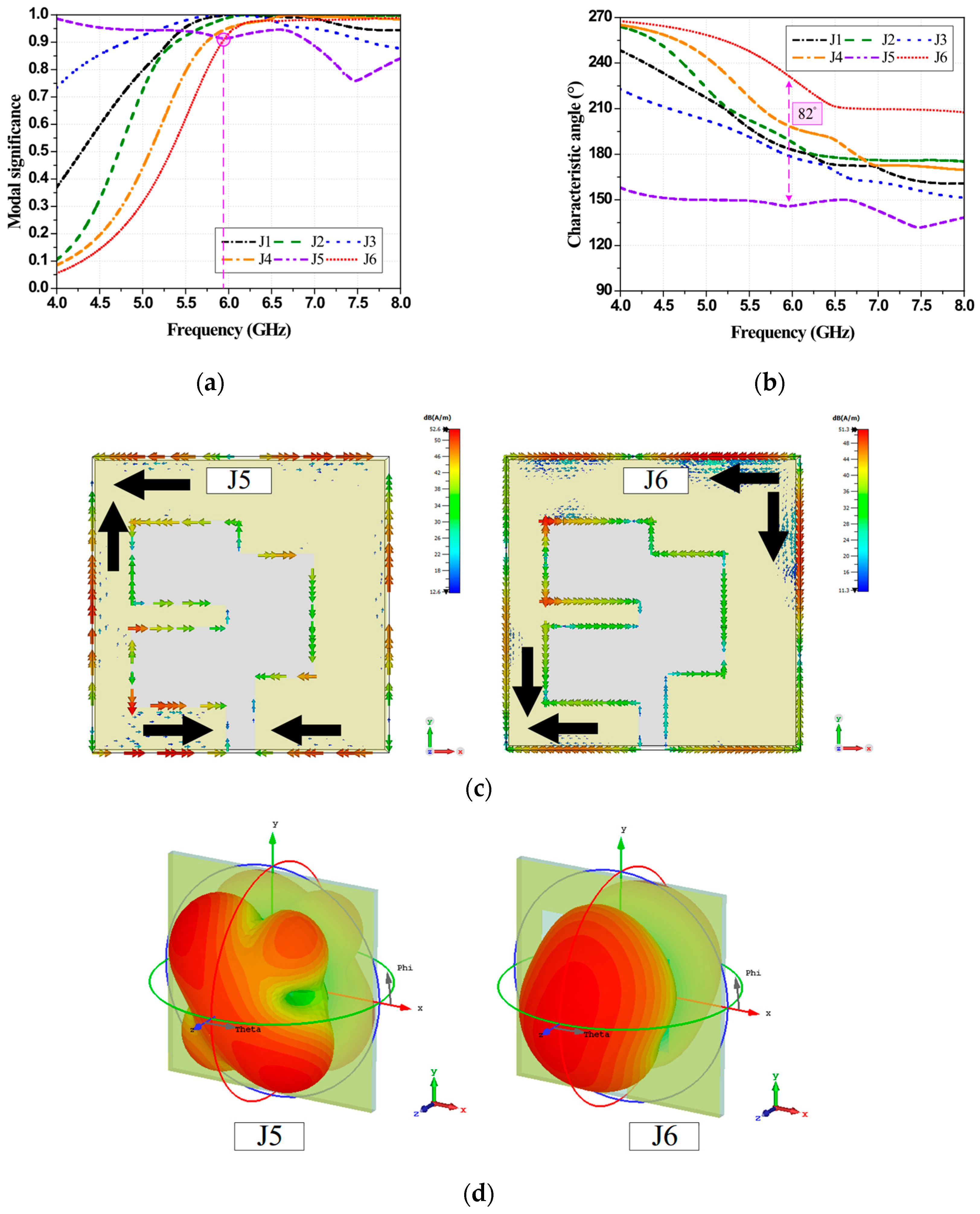
This study proposes a dual-element wideband circularly polarized (CP) slot-integrated multiple-input multiple-output (MIMO) antenna with an X-notch square-shaped artificial magnetic conductor (AMC) for dedicated short-range communications (DSRC) applications. The proposed antenna design consists of two substrate layers separated by an air gap. The upper layer features a dual-element coplanar waveguide-fed slot antenna and a defected ground structure decoupling isolator, while the lower layer comprises an 8 × 8 array of X-notch square-shaped elemental units, functioning as an AMC reflector. Characteristic mode analysis shows that circular polarization is produced by the dominant orthogonal mode pair (modes J5 and J6), whose modal significance exceeds 0.92 and whose characteristic angle separation is 82° around the 5.9 GHz DSRC band. An I-shaped slot embedded in the ground plane of the upper layer serves as a defected ground structure isolator to suppress mutual coupling between antenna elements. Meanwhile, the X-notch square AMC reflector enhances radiation characteristics and antenna gain. The measured return loss bandwidth and axial ratio bandwidth are 32% (4.72–6.61 GHz) and 21.18% (5.2–6.45 GHz), respectively. The dual-element antenna scheme achieves high isolation exceeding 19 dB, with a maximum gain of 8.6 dBic at 5.9 GHz. The envelop correlation coefficient remains below 0.003, while the diversity gain exceeds 9.98 dB.

1. Introduction

Dedicated short-range communications (DSRC) at 5.9 GHz underpins Vehicle-to-Everything (V2X) applications that require low latency and high reliability for safety-critical functions such as collision avoidance, traffic signal coordination, and emergency vehicle prioritization [1,2,3,4]. By enabling real-time exchange of safety information (e.g., speed, braking status, lane changes) among vehicles, infrastructure, and pedestrians, DSRC supports connected and autonomous mobility with improved road safety and transportation efficiency.
Multiple-input-multiple-output (MIMO) antenna technology employs multiple transmitting and receiving antennas to enhance communication performance [5]. Leveraging spatial diversity and multiplexing improves data rate, reliability, spectral efficiency, and coverage while reducing interference and multipath fading—capabilities that are crucial for high-speed vehicular environments where continuous connectivity is essential [6,7,8,9]. Circularly polarized (CP) slot-integrated MIMO antennas further mitigate polarization mismatch and orientation sensitivity, enabling stable V2X links under dynamic motion and multipath; spatial diversity also helps suppress fading and sustain high-performance connectivity for intelligent transportation networks [10,11,12].
Recent CP slot-integrated MIMO antennas confirm feasibility but reveal trade-offs among bandwidth, gain, isolation, and complexity. The dual-band hexagonal slot-integrated MIMO in [13] achieves bidirectional LHCP/RHCP with RLBW 11.43% (3.4–3.8 GHz), ARBW 7.14% (3.4–3.65 GHz), and 4.5 dBic gain, using an I-shaped isolator to raise isolation (>19 dB) while ECC remains below 0.12. The PEC-backed dual-element design in [14] reports very wide RLBW (82%, 2.9–7.1 GHz) and ARBW (68.5%, 3.1–6.35 GHz) with isolation > 22 dB and ECC < 0.003, yet the gain is modest (6 dBic) and reflector spacing increases profile. Wearable and quad-element variants in [15,16] extend operating bandwidths (RLBW 113.25%, 3.6–13 GHz; RLBW 64.9%, 5.37–11 GHz) with ARBW up to 58.6%, but gains remain mid single-digit (≤5.7 dBic) and isolation solutions add layout complexity. These works highlight a persistent tension between AR bandwidth, gain, isolation, and form factor [13,14,15,16].
Artificial magnetic conductors (AMCs) have been introduced to improve broadside gain and manage profile via near-in-phase reflection [17,18,19]. Single-element CP slot-integrated antennas with AMC reflectors in [20,21,22] demonstrate higher gains (e.g., 7.6–8.7 dBic) and useful AR responses, validating reflector benefits; however, these studies do not address MIMO-specific constraints such as inter-port isolation and ECC under close spacing. In CP slot-integrated MIMO, introducing a reflector can narrow AR bandwidth or exacerbate coupling if unit-cell phase and spacing are not co-designed; conversely, AMC-assisted surfaces can suppress surface waves and improve isolation when properly integrated [23,24]. Overall, closely related works typically enhance one or two metrics at the expense of others, and explicit mode-guided rationale for sustaining CP in compact dual-element layouts above a reflector remains limited [17,18,19,20,21,22,23,24].
This research targets that gap by proposing a dual-element wideband CP slot-integrated MIMO antenna for DSRC (5.2–6.45 GHz) that integrates an X-notch square AMC to raise broadside gain without sacrificing axial ratio bandwidth (ARBW) or inter-port isolation. Characteristic mode analysis guides the radiator geometry and element spacing by identifying the dominant orthogonal mode pair responsible for CP, while a compact ground modification interrupts principal coupling paths with minimal impact on self-matching. The antenna prototype achieves wide return loss bandwidth and ARBW, high isolation with very low ECC, and an application-friendly profile, thereby clarifying the bandwidth–gain–isolation–size trade-offs in CP slot-integrated MIMO with reflectors. Simulations were conducted with CST Microwave Studio Suite, and experiments were performed on an antenna prototype.

2. Antenna Design

2.1. The Proposed Dual-Element Wideband CP Slot-Integrated MIMO Antenna with X-Notch Sqaure AMC

Figure 1a–d illustrate the geometry of the proposed dual-element wideband CP slot-integrated MIMO antenna with an X-notch square AMC for DSRC applications. The proposed antenna scheme consists of two layers of FR-4 substrate separated by an air gap. Each substrate is 1.6 mm thick, with a dielectric constant (εr) of 4.3 and a loss tangent (tanδ) of 0.025.
The upper layer features the dual-element CP slot-integrated MIMO antenna separated by an I-shaped DGS isolator [25]. Each element of the dual-element CP slot-integrated MIMO antenna comprises a CPW-fed slot ground plane and a microstrip feed line, which is connected to a 50 Ω SMA connector. The lower layer consists of 8 × 8 X-notch square-shaped elemental units, functioning as a reflector. The detailed geometry and unit-cell parameters of the X-notch square AMC (period, patch size, notch width, substrate, and spacing) are provided in Section 2.2. Table 1 presents the optimal dimensions of the proposed antenna scheme.

2.2. Antenna Evolution Process

The development of the proposed dual-element wideband CP slot-integrated MIMO antenna with an X-notch square AMC follows four evolutionary steps. The first step involves two distinct evolution stages of a single-element slot-integrated antenna without a microstrip feed line.
First, CMA is applied to a single-element slot-integrated radiator to establish circular-polarization (CP) feasibility. Three layouts are examined using modal significance (MS), characteristic angle (CA), surface current distributions, and radiation patterns to identify the orthogonal mode pair that supports CP.
Second, a microstrip feed line is integrated into the single-element radiator, and full-wave simulations are conducted for the three layouts to quantify RLBW, ARBW, and gain. The results guide selection of the final single-element geometry by balancing impedance matching, CP bandwidth, and realized gain, while maintaining a compact footprint suitable for later arraying.
The design is then extended to a dual-element CP slot-integrated configuration and arranged in three placements to assess inter-port isolation, coupling paths, and diversity performance. The objective is to enhance isolation between elements while preserving CP quality and impedance match, ensuring that envelope correlation remains low without resorting to bulky external decouplers.
Finally, an AMC reflector composed of 8 × 8 X-notch square-shaped elemental units is designed and integrated beneath the radiator layer. The unit cell is characterized via reflection phase response and dispersion analysis, and the integrated stack is optimized for antenna–AMC spacing and array size to maximize broadside gain while sustaining wide RLBW/ARBW and the isolation achieved in the dual-element stage.
CMA is utilized to characterize the MS, CA, current distribution, and radiation patterns of the three layouts of the single-element slot-integrated antenna scheme. The entire current distribution (Jent) of the modal current distribution on the slot ground plane can be calculated using Equations (1) and (2) [26]:
J e n t = n = 1 N c n a n
c n = β n i 1 + j λ n
where cn is the modal weighting coefficient, an is the modal current distribution, β n i is the modal excitation coefficient, and λ n is the characteristic eigenvalue. To achieve CP radiation, the MS between two orthogonal modes at the target frequency band must be identical and greater than or equal to 0.707 (MS ≥ 0.707), while the phase difference between CA is approximately ±90°. The MS and CA can be calculated using Equations (3) and (4) [27]:
MS = 1 1 + j λ n
CA = 180 tan 1 ( λ n )
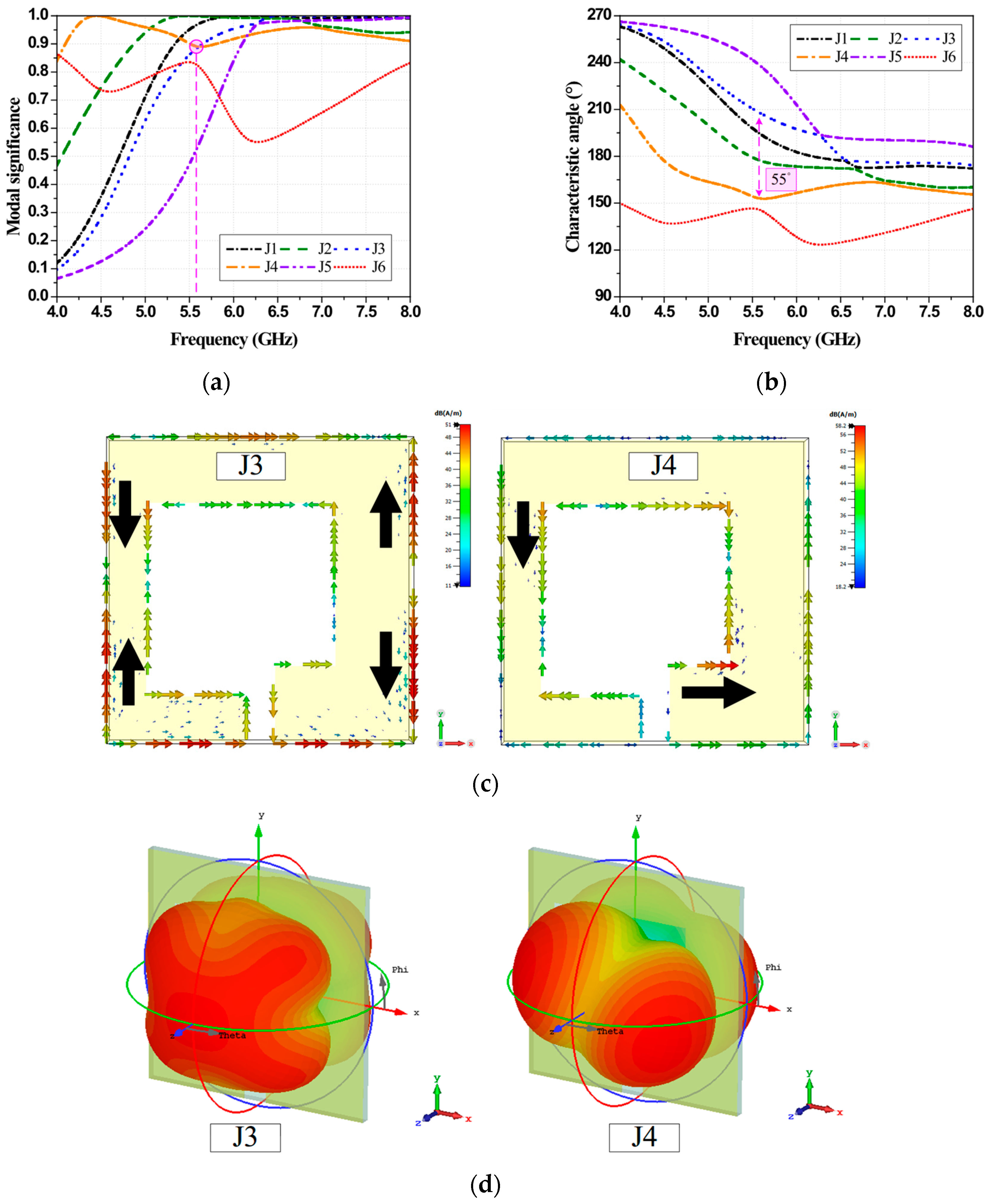
The first layout consists of a square-shaped copper plate (perfect electric conductor) with an asymmetric square-shaped slot on a lossless FR-4 substrate, as shown in Figure 2a. Figure 3a–d depict the CMA results for the first layout of the single-element slot-integrated antenna. Figure 3a presents the MS results for modes J1–J6. At 5.6 GHz, the MS of modes J3 and J4 is 0.88, which is greater than 0.707 and identical. In Figure 3b, the phase difference in CA between modes J3 and J4 at 5.6 GHz is 55°. In Figure 3c, mode J3 exhibits strong current distribution along the outer edge of the slot ground plane, whereas mode J4 demonstrates weak current distribution. Neither mode exhibits current distribution in orthogonal directions.
In Figure 3d, the 3D radiation patterns of modes J3 and J4 are non-symmetrical at the main lobe and non-orthogonal to each other. Consequently, the first layout does not achieve circular polarization. The full-wave method is used to evaluate the performance of the three layouts of the single-element slot-integrated antenna with a microstrip feed line connected to an SMA connector.
In the second layout, a rectangular-shaped stub is affixed to the right-hand corner of the slot ground plane, as illustrated in Figure 2b. Figure 4a–d illustrate the CMA results for the second layout of the single-element slot-integrated antenna. Figure 4a presents the MS results for modes J1–J6 of the second layout. Affixing a rectangular stub to the slot ground plane alters the two identical modes, resulting in modes J3 and J6. At 6.1 GHz, the MS of modes J3 and J6 is 0.91. The phase difference in CA between modes J3 and J6 at 6.1 GHz is 67°, as shown in Figure 4b. In Figure 4c, the currents of modes J3 and J6 are concentrated near the corners of the outer and inner edges of the slot ground plane, respectively. However, neither mode exhibits current distribution in orthogonal directions.
In Figure 4d, the radiation pattern of mode J3 is null radiated at the main lobe, while mode J6 exhibits a symmetrical lobe. As a result, the radiation patten of the second layout does not achieve circular polarization.
In the third layout, a strip-line stub is affixed at the center-left of the slot ground plane, as seen in Figure 2c. Figure 5a–d illustrate the CMA results for the third layout of the single-element slot-integrated antenna. Figure 5a shows the MS results for modes J1–J6 of the third layout. Affixing a strip-line stub at the center-left of the slot ground plane alters the two identical modes, resulting in modes J5 and J6. At 5.9 GHz, the MS of both modes is 0.92. The phase difference in CA between modes J5 and J6 at 5.9 GHz is 82°, as illustrated in Figure 5b. In Figure 5c, the currents of modes J5 and J6 flow along the edges of the slot ground plane in orthogonal directions. In Figure 5d, the radiation patterns of modes J5 and J6 form a symmetrical lobe and are orthogonal to each other. Consequently, the radiation pattern of the third layout achieves circular polarization.
In Figure 6a–c, the simulated RLBW, ARBW, and maximum gain of the first layout cover 4.93–6.68 GHz, 5.56–5.74 GHz, and 2.46 dBic at 5.3 GHz, respectively. The simulated RLBW, ARBW, and maximum gain of the second layout cover 4.63–6.77 GHz, 5.81–6.76 GHz, and 1.38 dBic at 6 GHz, respectively. The simulated RLBW, ARBW, and maximum gain of the third layout cover 4.7–6.95 GHz, 5.19–6.53 GHz, and 3.51 dBic at 5.6 GHz, respectively. The results indicate that the third layout achieves a wide RLBW and ARBW with optimal gain. Table 2 tabulates the comparison results of three layouts, including geometry change, CMA results, RLBW, ARBW, and gain.
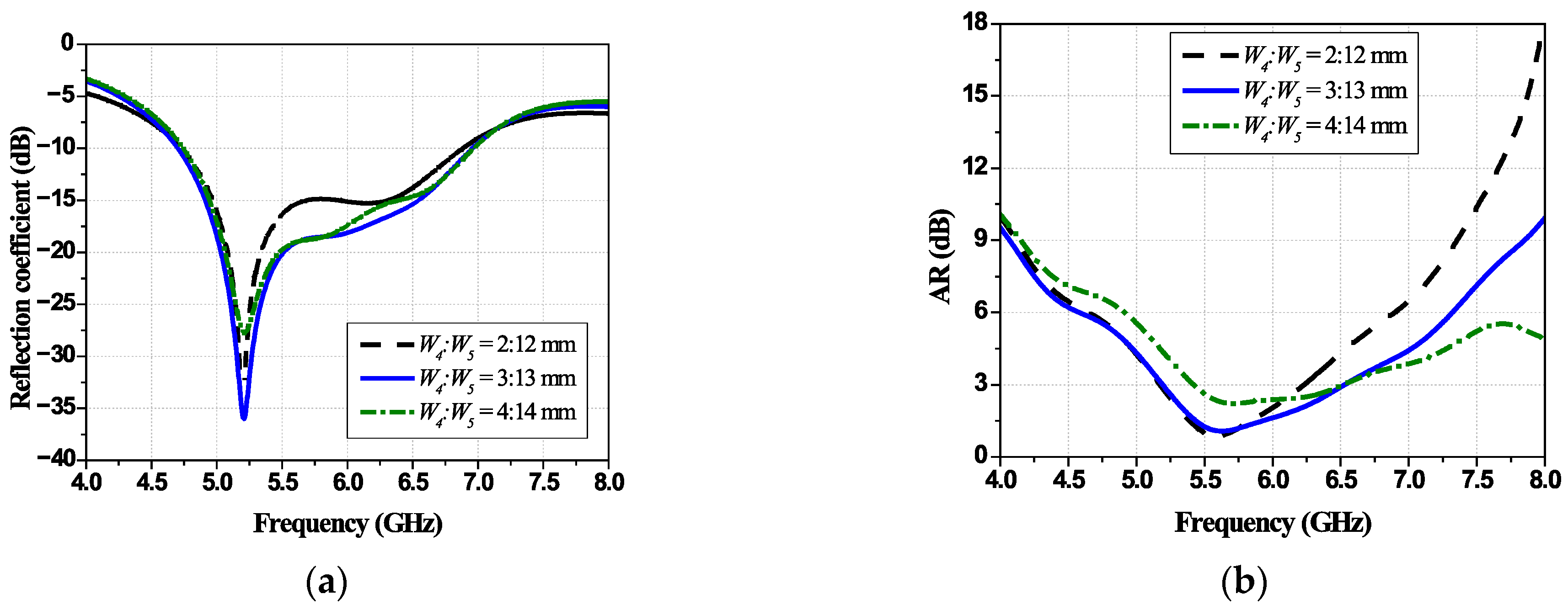
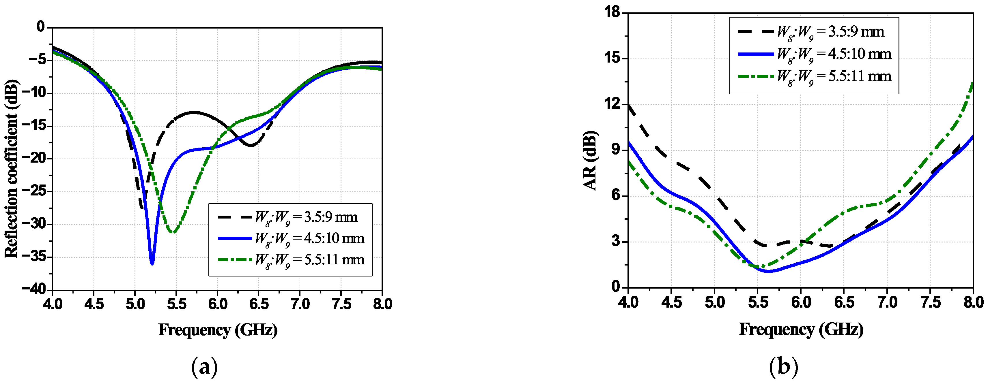
A parametric study of the third layout evaluates how the two stubs affect the single-element slot-integrated antenna’s RLBW and ARBW. Two-dimension ratios are swept: W4:W5 for the center-left strip-line stub and W8:W9 for the right-corner rectangular stub. The resulting trends indicate how stub geometry should be selected to maximize RLBW and ARBW while maintaining good impedance matching.
Figure 7a–b show the simulated RLBW and ARBW under different ratios W4:W5: 2:12, 3:13, and 4:14 mm. In Figure 7a, the RLBW for W4:W5 = 3:13 mm and 4:14 mm is nearly identical (4.7–6.95 GHz). In Figure 7b, increasing W4:W5 shifts the ARBW slightly toward higher frequency; the 3:13 mm provides the widest ARBW within the target band. Thus, W4:W5 = 3:13 mm is selected as optimal.
Figure 8a,b show the simulated RLBW and ARBW under different ratios W8:W9: 3.5:9, 4.5:10, and 5.5:11 mm. In Figure 8a, the RLBW remains essentially unchanged for all ratios (4.7–6.95 GHz). As shown in Figure 8b, increasing W8:W9 shifts the ARBW slightly toward lower frequency; the 4.5:10 mm provides the widest ARBW within the target band. Therefore, W8:W9 = 4.5:10 mm is selected as optimal.
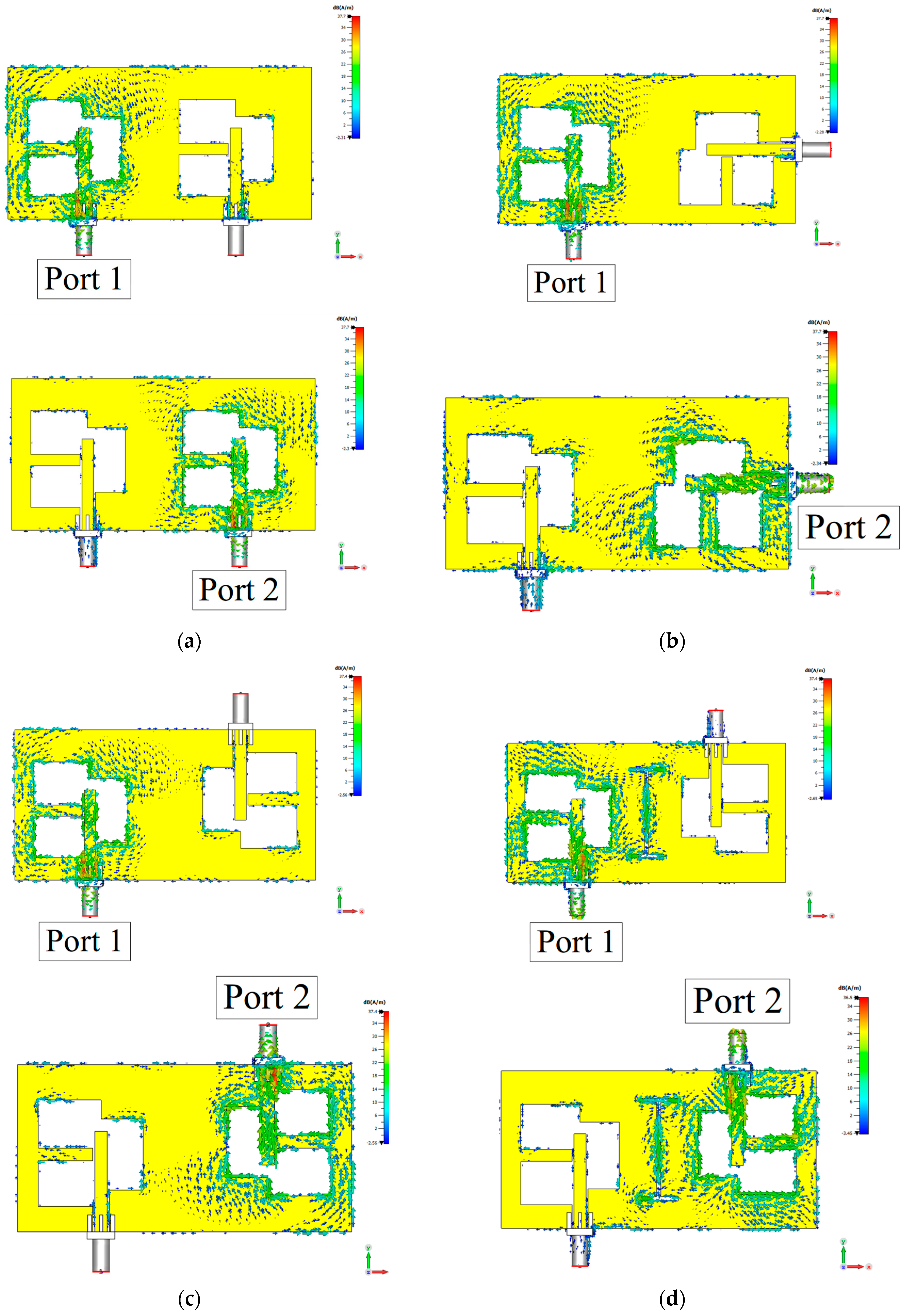
Figure 9a–d illustrate the surface current distribution of the dual-element antenna scheme in various configurations: parallel, orthogonal, opposite, and opposite with an I-shaped slot DGS isolator. The I-shaped slot between antenna elements 1 and 2 employs the DGS decoupling technique to enhance isolation improvement.
In the parallel configuration, both antenna elements exhibit strongly concentrated current distributions, as shown in Figure 9a. In the orthogonal configuration, the current distribution on element 1 becomes comparatively weaker, while element 2 manifests an intense current concentration between the antenna elements, as illustrated in Figure 9b.
In the opposite configuration, an intense current concentration between both antenna elements is observed, as shown in Figure 9c. In Figure 9d, the current concentration between the antenna elements is suppressed by the I-shaped slot DGS isolator.
To analyze the mutual coupling mechanism between the antenna elements, the electric field on the antenna structure is evaluated. Figure 10 illustrates the simulated electric field magnitude in the XY-plane at 5.5 GHz.
In the parallel configuration, the E-field magnitudes at the center (x = 0 mm) of antenna elements 1 and 2 are 54.56 V/m and 66.83 V/m, respectively, indicating strong coupling. In the orthogonal configuration, the E-field magnitude of element 1 decreases to 48.2 V/m, while that of element 2 increases to 85 V/m. Despite orthogonal excitation, element 2 still exhibits significantly high coupling.
In the opposite configuration, the E-field magnitudes of elements 1 and 2 are identical at 51.2 V/m. In the opposite configuration with an I-shaped slot DGS isolator, the E-field magnitude of both elements decrease to 38.4 V/m, effectively reducing mutual coupling between the dual elements.
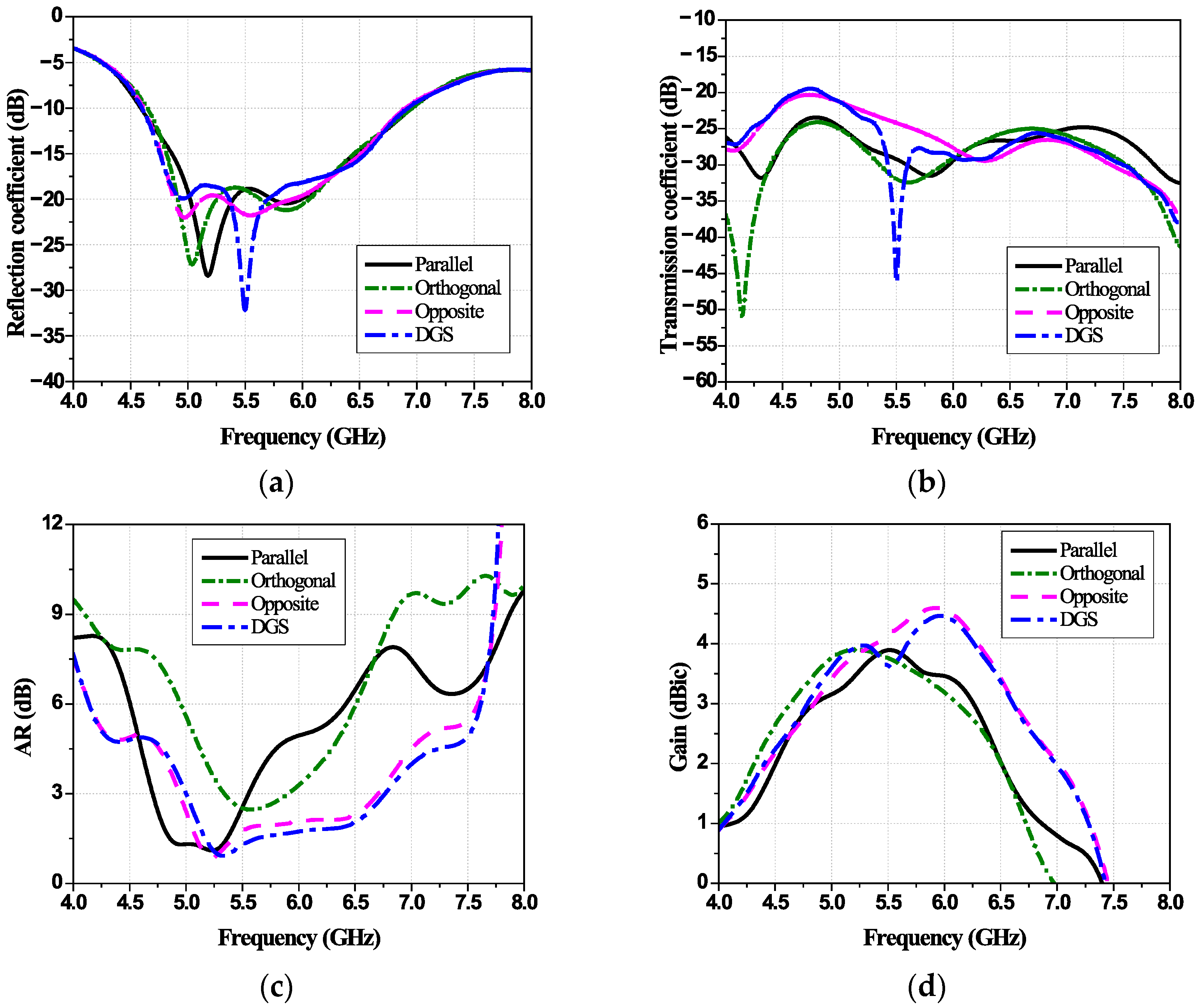
Figure 11a–d illustrate the simulated results of the dual-element antenna scheme for various configurations. In Figure 11a, the simulated RLBW of all configurations spans a similar frequency range (4.95–6.95 GHz). In Figure 11b, the simulated isolation values (|S21|) of the parallel, orthogonal, opposite, and opposite with an I-shaped slot DGS isolator configurations are less than 24.2 dB, 24.6 dB, 21 dB, and 21 dB, respectively. The corresponding simulated ARBW values are 4.7–5.55 GHz, 5.34–5.9 GHz, 4.94–6.7 GHz, and 5–6.77 GHz, as shown in Figure 11c. In Figure 11d, the maximum gains are 3.91 dBic at 5.5 GHz for the parallel configuration, 3.9 dBic at 5.2 GHz for the orthogonal configuration, 4.61 dBic at 5.9 GHz for the opposite configuration, and 4.47 dBic at 6 GHz for the configuration with a DGS isolator.
Despite high isolation in the parallel and orthogonal configurations, their ARBW remains narrow. The simulated RLBW and ARBW of the opposite configuration without and with a DGS isolator are similar. However, the opposite configuration with an I-shaped slot DGS isolator achieves higher isolation and gain, particularly in the 5–6.2 GHz frequency range.
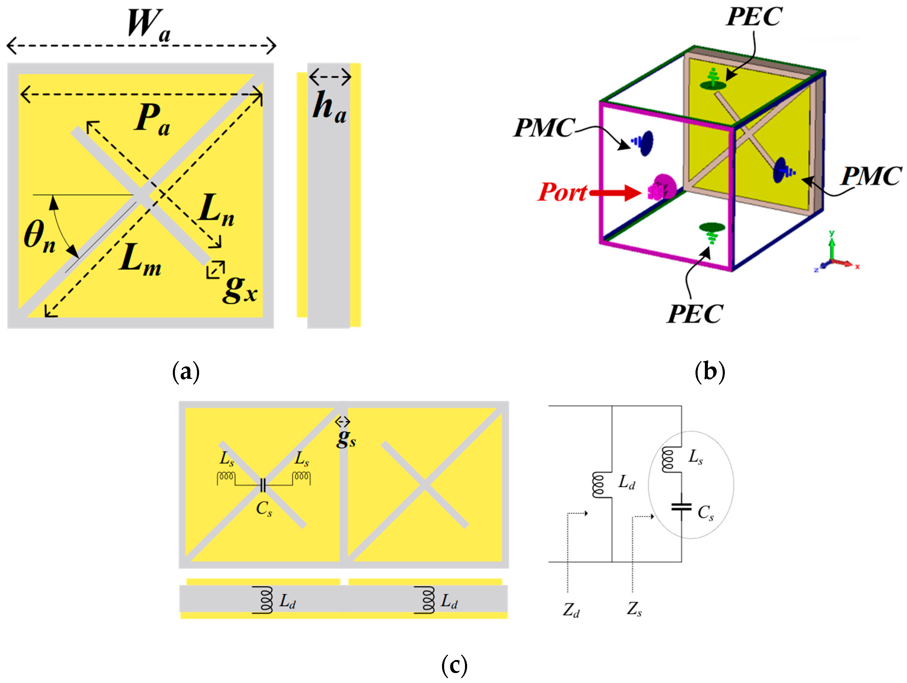
Figure 12a–c illustrate the configuration, boundary setup, and equivalent circuit model of an X-notch square elemental unit. In Figure 12a, an asymmetric X-notch square elemental unit is positioned on a 12 mm × 12 mm (Wa × Wa) FR-4 substrate, with a thickness of 1.6 mm (ha), εr of 4.3, and tanδ of 0.025. Each X-notch square elemental unit consists of a square patch with an X-notch slot and a ground plane. The dimension of the square patch is 11 mm × 11 mm (Pa × Pa). The X-notch slot comprises major- and minor-diagonal arms, with dimensions of 15.06 mm × 0.5 mm (Lm × gx) and 5.5 mm × 0.5 mm (Ln × gx), respectively. The minor-diagonal arm is tilted at an angle of 45° (θn).
In Figure 12b, the boundary condition [28] of the X-notch square elemental unit is defined by PMC and PEC in ±x and ±y directions. The excited port and PEC ground plane are positioned along the +z and −z axes. The resonant frequency is determined by Equation (5) [29]:
f r = 1 2 π ( L s + L d ) C s
where Ls and Cs represent the equivalent inductance and capacitance of the X-notch square elemental unit, and Ld denotes the dielectric inductance of the FR-4 substrate. The capacitance (Cs) can be determined by Equations (6) and (7) [30]:
C s = 2 W ε 0 ε r e f f π cosh 1 a g s
ε r e f f = ε r + 1 / 2
where W represents the width of the square-shaped patch, gs denotes the gap between a pair of X-notch square elemental units, and a is given by 2(Lm + Ln) + gs. The bandwidth of the X-notch square elemental unit is determined using Equation (8):
B W = π 8 η 0 L d + L s C s × L d L d + L s 2
In Figure 12c, the equivalent circuit model of the X-notch square elemental unit consists of an inductor (Ld) in parallel with a series circuit of inductor (Ls) and capacitor (Cs). The total surface impedance is determined using Equation (9):
Z t ( ω ) = Z s Z d = j ω L d 1 ω 2 L s C s 1 ω 2 ( L s + L d ) C s
where Zs represents the impedance of the X-notch AMC and Zd denotes the impedance of the dielectric slab.
To achieve in-phased current, the surface currents induced by an antenna positioned above the AMC reflector align with and reflect in the same direction as the antenna’s original currents. This phenomenon occurs when the operating frequency of the antenna is within the frequency range of the AMC elemental unit, where the reflection phase is approximately 0° [31].
A parametric study is conducted to optimize the reflection phase of the X-notch square elemental unit by varying the tilting angle of the minor-diagonal arm (θn), the length of the minor-diagonal arm (Ln), and the width of the diagonal arm (gx). Figure 13a–c illustrate the simulated reflection phase of the X-notch square elemental unit for various θn, Ln, and gx, respectively.
Figure 13a illustrates the simulated reflection phase for different values of θn: 0°, 45°, and 90°. A reflection phase of 0° is observed at 6.24 GHz, 5.9 GHz, and 6.11 GHz for θn of 0°, 45°, and 90°, respectively. Figure 13b presents the simulated reflection phase for various values of Ln: 3.5, 5.5, and 7.5 mm. The 0° reflection phase occurs at 6.3 GHz, 5.9 GHz, and 5.57 GHz, respectively. Figure 13c shows the simulated reflection phase for different values of gx: 0.2, 0.5, and 0.8 mm. The reflection phase shifts to lower frequencies as gx increases. The 0° reflection phase is observed at 6.1 GHz, 5.9 GHz, and 5.8 GHz for gx of 0.2, 0.5, and 0.8 mm, respectively. The optimal parameters at the center frequency of 5.9 GHz are θn = 45°, Ln = 5.5 mm, and gx = 0.5 mm, achieving a 0° reflection phase. With a ±90° reflection phase, the operating frequency band of the X-notch square elemental unit spans 5.3–7 GHz.
A dispersion diagram is utilized to analyze the AMC mechanism. It describes the relationship between the phase constant (β), wave number (k), and propagation modes, which exhibit different phases and group velocities. The dispersion diagram also identifies the bandgap regions where surface wave propagation is suppressed, with the suppressed bandgap determined by the dispersion characteristics that define the surface wave characteristic.
As shown in Figure 14a, periodic boundary conditions are applied to the ±x and ±y axes to define the boundary conditions of the dispersion diagram. The PMC and PEC are assigned to the +z and -z axes, respectively. In Figure 14b, the suppressed bandgap is observed between modes 1 (TM mode) and 2 (TE mode), spanning 5.4–6.1 GHz, indicating that the bandgap suppresses surface waves within this frequency range [32].
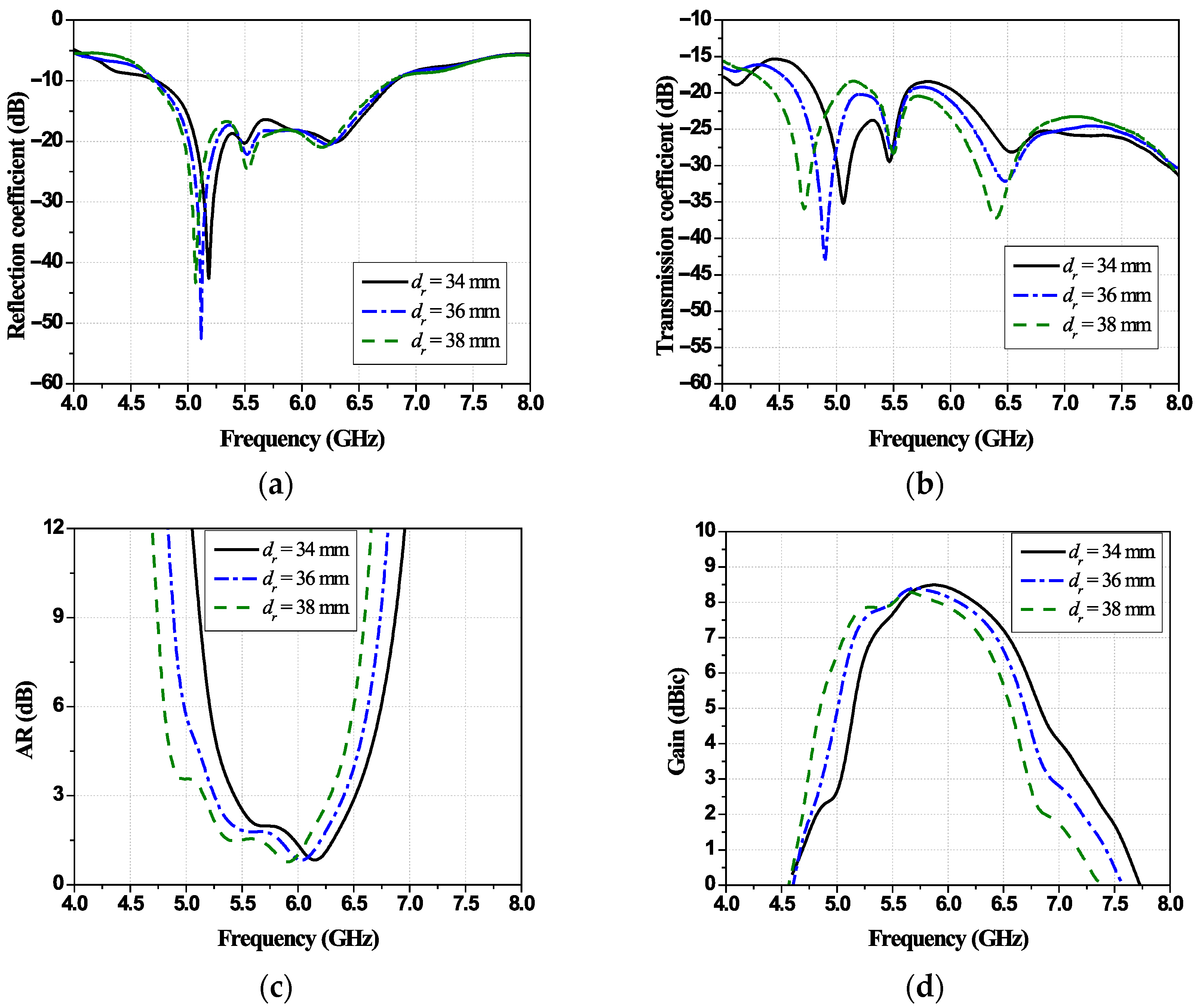
Figure 15a–d illustrate the simulated RLBW, isolation, ARBW, and gain for different distances between the proposed antenna and the AMC (dr): 34, 36, and 38 mm. In Figure 15a, the simulated RLBW of the antenna scheme spans 4.7–6.8 GHz, with simulated isolation values greater than 17 dB, 19 dB, and 18.4 dB for dr of 34, 36, and 38 mm, respectively, as shown in Figure 15b. Figure 15c presents the simulated ARBW of 5.43–6.51 GHz, 5.25–6.41 GHz, and 5.15–6.2 GHz, with corresponding maximum gains of 8.4 dBic at 5.9 GHz, 8.42 dBic at 5.7 GHz, and 8.32 dBic at 5.6 GHz, as shown in Figure 15d. At dr = 36 mm, the proposed antenna scheme achieves wide RLBW and ARBW along with high isolation. The optimal value of dr is 36 mm.
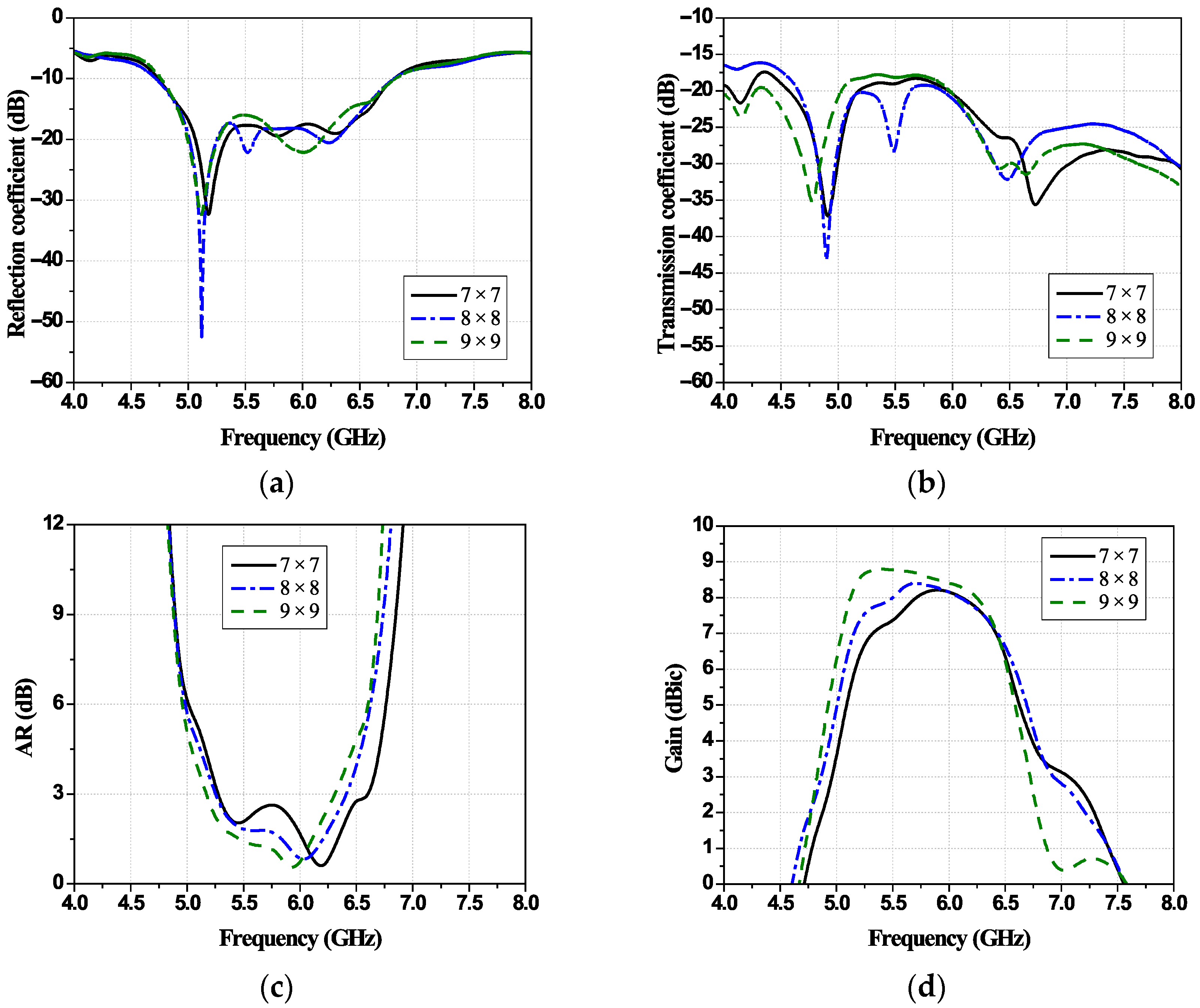
Figure 16a–d illustrate the simulated RLBW, isolation, ARBW, and gain for different numbers of X-notch square elemental units: 7 × 7, 8 × 8, and 9 × 9. In Figure 16a, the simulated RLBW values are 4.74–6.8 GHz, 4.7–6.8 GHz, and 4.76–6.8 GHz, respectively, with simulated isolation exceeding 18.2 dB, 19 dB, and 17.7 dB, as shown in Figure 16b. Figure 16c presents the simulated ARBW of 5.28–6.5 GHz, 5.25–6.41 GHz, and 5.17–6.31 GHz, with corresponding maximum gains of 8.23 dBic at 5.9 GHz, 8.42 dBic at 5.7 GHz, and 8.8 dBic at 5.4 GHz, as shown in Figure 16d. The proposed antenna scheme achieves wide bandwidth and high isolation with 8 × 8 X-notch square elemental units. Consequently, the optimal number of AMC elemental units is 8 × 8.
An AMC was chosen rather than a metal ground because its near-zero reflection phase around the 5.9 GHz DSRC band supports in-phase image currents and avoids the 180° phase flip of a PEC, which typically forces ≈λ/4 spacing for constructive broadside radiation. The final antenna–AMC separation of 36 mm was not set by phase alone, but by jointly optimizing realized gain, ARBW, and inter-port isolation for a finite 8 × 8 AMC aperture.
In practice, the unit cell’s reflection phase varies with frequency and incidence angle, while edge diffraction and finite size alter the effective phase over the bandwidth, pushing the optimum beyond the simple λ/4 rule of thumb. At smaller gaps (≈15–20 mm), AR detuning and stronger image-mediated coupling (worse isolation/ECC) were observed, whereas around 34–38 mm, the CP bandwidth broadened, and isolation improved without sacrificing gain. We therefore chose dr = 36 mm (≈0.7λ0 at 5.9–6.0 GHz) as the optimal compromise across gain, CP bandwidth, and isolation, while keeping the overall profile < 40 mm for practical vehicular integration.

3. Experimental Results and Discussion

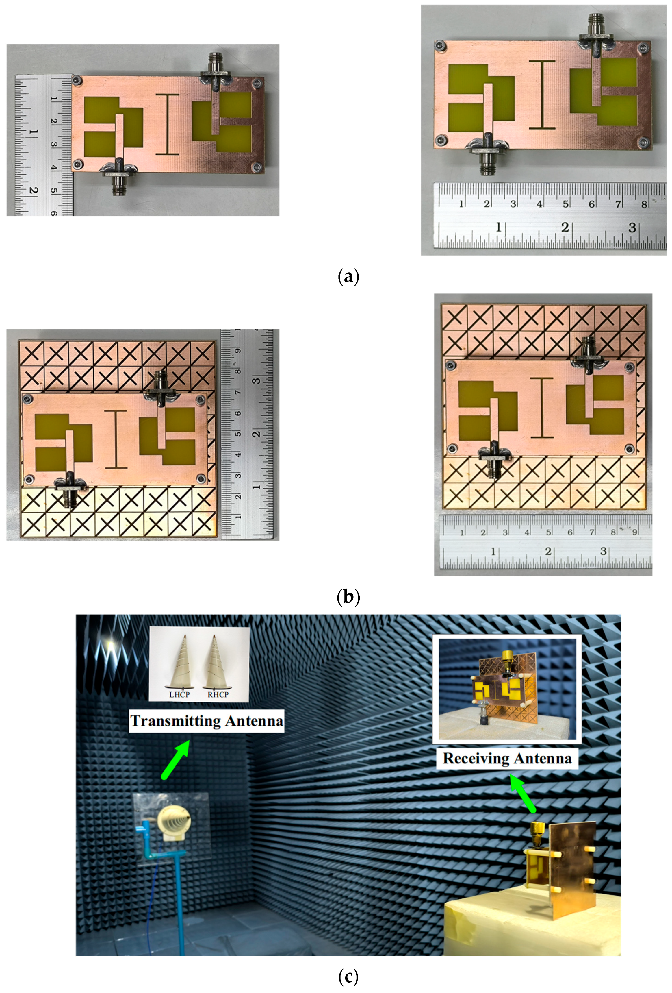
Figure 17a,b show a prototype of the proposed dual-element wideband CP slot-integrated MIMO antenna with X-notch square AMC. In the experimental setup, a pair of log-spiral antennas (ETS-Lindgren Model 3102) serve as the transmitting antennas, and the proposed antenna scheme functions as the antenna under test (AUT).
In Figure 17c, the transmitting antennas and AUT are evaluated in an anechoic chamber using a vector network analyzer (Rohde & Schwarz model ZNB26). The far-field distance between the transmitting antennas and the AUT is 3 m.
The AR of the transmitting antennas and the AUT is determined by the co-polar and cross-polar components in the E- and H-planes. The co-polar and cross-polar electric-field components are represented by |ERHCP| and |ELHCP|, corresponding to right-hand circular polarization and left-hand circular polarization, respectively. The AR of the antenna prototype is calculated using Equation (10) [33]:
AR   ( dB )   =   20 log E R H C P + E L H C P E R H C P E L H C P
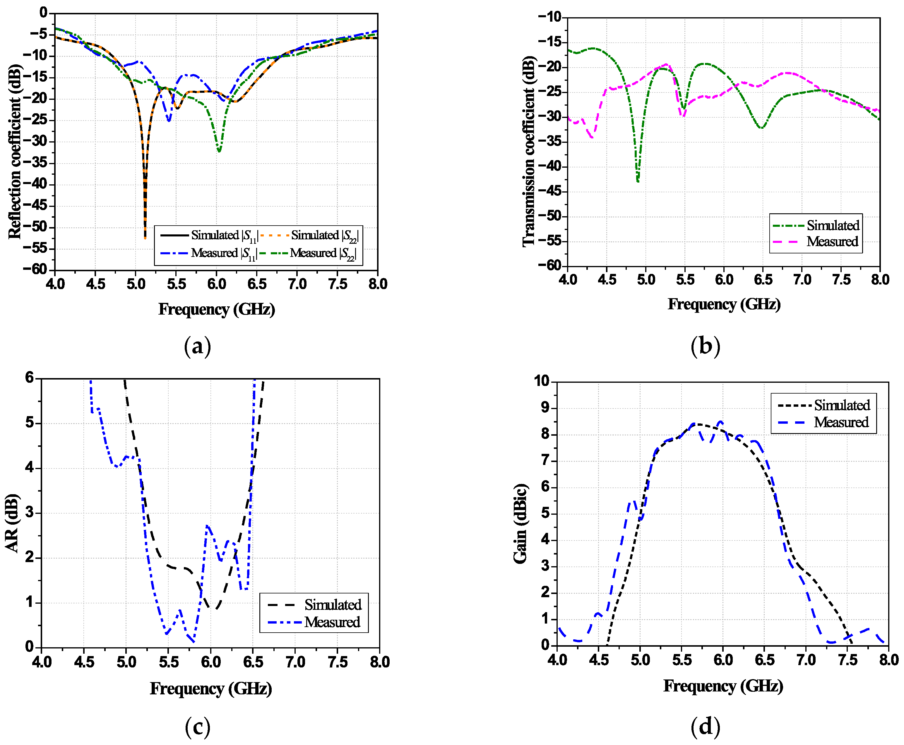
Figure 18a–d illustrate the simulated and measured results of the proposed dual-element CP slot-integrated MIMO antenna with an X-notch square AMC. In Figure 18a, the simulated and measured RLBW (|S11| and |S22| ≤ −10 dB) span 4.7–6.8 GHz and 4.72–6.61 GHz, respectively. The simulated and measured isolation values (|S21|) exceed 19 dB, as shown in Figure 18b. In Figure 18c, the simulated and measured ARBW (AR ≤ 3 dB) are 5.25–6.41 GHz and 5.2–6.45 GHz, respectively, with corresponding maximum gains of 8.42 dBic at 5.7 GHz and 8.6 dBic at 5.9 GHz, as shown in Figure 18d.
Figure 19a–d illustrate the simulated and measured XZ- and YZ-plane radiation patterns for antenna elements 1 and 2 of the proposed antenna scheme at 5.4 GHz and 5.9 GHz. The simulated and measured results of both elements show good agreement.
The envelope correlation coefficient (ECC) is employed to evaluate radiation pattern diversity and mutual coupling between antenna elements. The ECC for the proposed dual-element antenna scheme is calculated using Equations (11) and (12) [34]:
ECC = 4 π ρ 1 ( θ , ϕ ) ρ 2 ( θ , ϕ ) d Ω 2 4 π ρ 1 ( θ , ϕ ) 2 d Ω 4 π ρ 2 ( θ , ϕ ) 2 d Ω
ρ 1 ( θ , ϕ ) ρ 2 ( θ , ϕ )   = ρ θ 1 ( θ , ϕ ) ρ θ 2 ( θ , ϕ ) + ρ ϕ 1 ( θ , ϕ ) ρ ϕ 2 ( θ , ϕ )
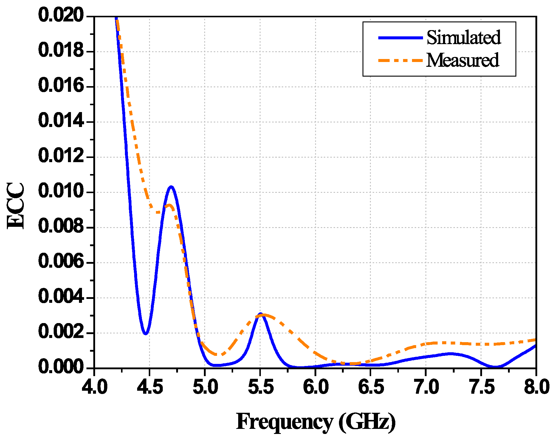
where ρ 1 ( θ , ϕ ) and ρ 2 ( θ , ϕ ) represent the electric-field vectors of elements 1 and 2, respectively, and Ω denotes the solid angle. As shown in Figure 20, the simulated and measured ECC of the proposed dual-element antenna scheme remains below 0.003 across the ARBW.
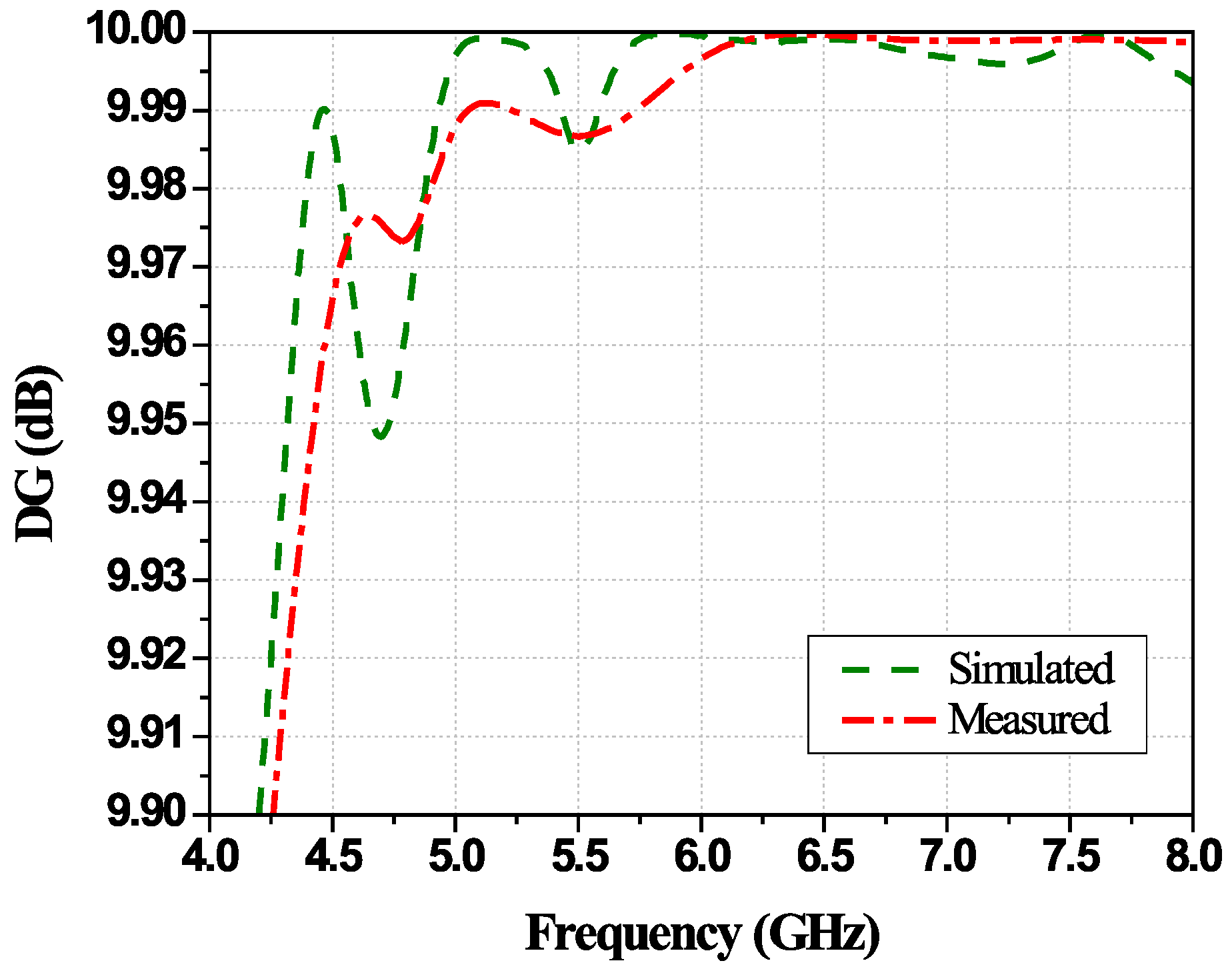
Diversity gain (DG) quantifies the reduction in signal fading caused by multipath propagation and is used to evaluate the signal reliability of the dual-element MIMO antenna. The DG between antenna elements can be calculated using Equation (13) [35]. As shown in Figure 21, the simulated and measured DG of the proposed dual-element antenna scheme exceed 9.98 dB.
DG = 10 1 ECC 2
Table 3 presents a performance comparison between existing MIMO antennas with a reflector and the proposed dual-element CP slot-integrated MIMO antenna with an X-notch square AMC. In [36], a compact chair-shaped 1 × 2 MIMO antenna was proposed for 5G sub-6 GHz applications. The antenna utilized parasitic elements and a single-layer circular-slot square frequency-selective surface to enhance gain and isolation. The single-element antenna consisted of a CPW-fed line and a slot-integrated ground plane. Despite its wide RLBW and high gain, the antenna’s isolation remained low.
In [37], a CP MIMO antenna with modified coplanar ground planes was proposed for WLAN, WiMAX, and other commercial applications. An etched rectangular slot, asymmetric ground geometry, and a PEC reflector were employed to improve ARBW. Despite its wide RLBW, high isolation, and low ECC, the antenna suffered from low gain. In [38], a compact wideband CP MIMO antenna with a PEC reflector was proposed for wearable applications. The antenna comprised a CPW-fed line and asymmetrically modified ground planes. The PEC reflector, fabricated from a high-permittivity substrate, enabled unidirectional radiation and reduced body-loading sensitivity. Despite its high isolation and low ECC, the antenna’s gain remained low. In [39], a two-element triple-band MIMO antenna with a metasurface reflector was proposed for WLAN applications. The single triple-band MIMO antenna consisted of a microstrip feed line and a DGS isolator. Despite tri-band frequency operation, the antenna suffered from narrow RLBW and low gain.
The overall profile is higher than several referenced works because the selected antenna–AMC separation (36 mm) maximizes the combined objectives of realized gain, 3 dB ARBW, and inter-port isolation for a finite 8 × 8 AMC. A thinner form factor can be pursued in future designs through several methods: miniaturizing the AMC into a higher-impedance mushroom/via-loaded HIS, or employing a dual-layer/multi-resonant AMC to retain near-zero reflection phase at smaller spacings; employing a higher-permittivity or magneto-dielectric spacer to shorten the effective cavity while preserving the broadside constructive condition; co-designing the radiator and AMC as a shallow cavity (e.g., phase-flattened or weak-gradient AMC) to recover broadside gain at reduced spacing; and shifting more of the isolation burden to element-level techniques (e.g., compact DGS/EBG or neutralization) so spacing can be reduced without an ECC penalty. Additional measures include low-profile feeds/connectors and platform co-integration; as an alternative path, metasurface partial-reflector superstrates (PRSs) may offer low-profile beam collimation, provided that CP bandwidth and isolation are maintained.

4. Conclusions

This study proposes a dual-element wideband CP slot-integrated MIMO antenna with an X-notch square-shaped AMC for DSRC applications. The antenna structure consists of two layers of substrate separated by an air gap. The upper layer features a dual-element slot-integrated CP MIMO antenna, while the lower layer is the X-notch square AMC. Each antenna element in the dual-element MIMO antenna scheme is excited by a microstrip feed line. To achieve CP radiation, CMA is employed to characterize circular polarization generated by exciting two orthogonal modes, J5 and J6. An I-shaped slot embedded in the ground plane of the upper layer serves as a DGS isolator to suppress mutual coupling between the antenna elements. The AMC is realized by using an 8 × 8 array of X-notch square elemental units, which functions as a reflector to enhance radiation and antenna gain. The measured RLBW and ARBW values are 32% (4.72–6.61 GHz) and 21.18% (5.2–6.45 GHz), respectively. The proposed dual-element antenna scheme achieves high isolation exceeding 19 dB, with a maximum gain of 8.6 dBic at 5.9 GHz. The ECC remains below 0.003, while its DG exceeds 9.98 dB. The proposed dual-element antenna scheme is highly suitable for V2X communication systems.

Author Contributions

Conceptualization, C.M., N.S. and J.K.; methodology, C.M., N.S. and J.K.; software, C.M.; validation, N.S. and J.K.; formal analysis, C.M. and N.S.; investigation, J.K.; resources, N.S.; data curation, J.K.; writing—original draft preparation, C.M.; writing—review and editing, J.K.; visualization, N.S.; supervision, J.K.; project administration, P.A.; funding acquisition, P.C. All authors have read and agreed to the published version of the manuscript.

Funding

This work was supported by King Mongkut’s University of Technology North Bangkok under Contract KMUTNB-FF-68-B-27.

Institutional Review Board Statement

Not applicable.

Informed Consent Statement

Not applicable.

Data Availability Statement

Data are provided in the manuscript.

Conflicts of Interest

The authors declare no conflicts of interest.

References

  1. Zhou, H.; Xu, W.; Chen, J.; Wang, W. Evolutionary V2X Technologies Toward the Internet of Vehicles: Challenges and Opportunities. Proc. IEEE 2020, 108, 308–323. [Google Scholar] [CrossRef]
  2. Saad, M.M.; Khan, M.T.R.; Shah, S.H.A.; Kim, D. Advancements in Vehicular Communication Technologies: C-V2X and NR-V2X Comparison. IEEE Commun. Mag. 2021, 59, 107–113. [Google Scholar] [CrossRef]
  3. Molina-Masegosa, R.; Gozalvez, J. LTE-V for Sidelink 5G V2X Vehicular Communications: A New 5G Technology for Short-Range Vehicle-to-Everything Communications. IEEE Veh. Technol. Mag. 2017, 12, 30–39. [Google Scholar] [CrossRef]
  4. Abou-Zeid, H.; Pervez, F.; Adinoyi, A.; Aljlayl, M.; Yanikomeroglu, H. Cellular V2X Transmission for Connected and Autonomous Vehicles Standardization, Applications, and Enabling Technologies. IEEE Consum. Electron. Mag. 2019, 8, 91–98. [Google Scholar] [CrossRef]
  5. Guo, H.; Wymeersch, H.; Makki, B.; Chen, H.; Wu, Y.; Durisi, G.; Keskin, M.F.; Moghaddam, M.H.; Madapatha, C.; Yu, H.; et al. Integrated Communication, Localization, and Sensing in 6G D-MIMO Networks. IEEE Wirel. Commun. 2025, 32, 214–221. [Google Scholar] [CrossRef]
  6. Jeon, J.; Lee, G.; Ibrahim, A.A.; Yuan, J.; Xu, G.; Cho, J.; Onggosanusi, E.; Kim, Y.; Lee, J.; Zhang, J.C. MIMO Evolution toward 6G: Modular Massive MIMO in Low-Frequency Bands. IEEE Commun. Mag. 2021, 59, 52–58. [Google Scholar] [CrossRef]
  7. Shlezinger, N.; Ma, M.; Lavi, O.; Nguyen, N.T.; Eldar, Y.C.; Juntti, M. Artificial Intelligence-Empowered Hybrid Multiple-input/multiple-output Beamforming: Learning to Optimize for High-Throughput Scalable MIMO. IEEE Veh. Technol. Mag. 2024, 19, 58–67. [Google Scholar] [CrossRef]
  8. Rodríguez-Corbo, F.A.; Celaya-Echarri, M.; Shubair, R.M.; Falcone, F.; Azpilicueta, L. Spatial MIMO Channel Characterization Under Different Vehicular Distributions. IEEE Antennas Wirel. Propag. Lett. 2024, 23, 3163–3167. [Google Scholar] [CrossRef]
  9. SRoger, S.; Martin-Sacristan, D.; Garcia-Roger, D.; Monserrat, J.F.; Kousaridas, A.; Spapis, P.; Ayaz, S. 5G V2V Communication With Antenna Selection Based on Context Awareness: Signaling and Performance Study. IEEE Trans. Intell. Transp. Syst. 2022, 23, 1044–1057. [Google Scholar] [CrossRef]
  10. Ullah, S.; He, Y.; Huang, Y. A Triband Circular-Polarized Four-Port MIMO Antenna With Compact Size and Low Mutual Coupling. IEEE Antennas Wirel. Propag. Lett. 2025, 24, 621–625. [Google Scholar] [CrossRef]
  11. Sufian, A.; Hussain, N.; Abbas, A.; Lee, J.; Park, S.G.; Kim, N. Mutual Coupling Reduction of a Circularly Polarized MIMO Antenna Using Parasitic Elements and DGS for V2X Communications. IEEE Access 2022, 10, 56388–56400. [Google Scholar] [CrossRef]
  12. Sahu, N.K.; Das, G.; Gangwar, R.K.; Rambabu, K. An Arrangement for Four-Element MIMO DRA With Complementary CP Diversity. IEEE Antennas Wirel. Propag. Lett. 2021, 20, 1616–1620. [Google Scholar] [CrossRef]
  13. Saxena, S.; Kanaujia, B.K.; Dwari, S.; Kumar, S.; Choi, H.C.; Kim, K.W. Planar Four-Port Dual Circularly-Polarized MIMO Antenna for Sub-6 GHz Band. IEEE Access 2020, 8, 90779–90791. [Google Scholar] [CrossRef]
  14. Ullah, U.; Ben Mabrouk, I.; Koziel, S.; Al-Hasan, M. Implementation of Spatial/Polarization Diversity for Improved-Performance Circularly Polarized Multiple-Input-Multiple-Output Ultra-Wideband Antenna. IEEE Access 2020, 8, 64112–64119. [Google Scholar] [CrossRef]
  15. Kumar, S.; Nandan, D.; Srivastava, K.; Kumar, S.; Singh, H.; Marey, M.; Mostafa, H.; Kanaujia, B.K. Wideband Circularly Polarized Textile MIMO Antenna for Wearable Applications. IEEE Access 2021, 9, 108601–108613. [Google Scholar] [CrossRef]
  16. Kollipara, V.; Peddakrishna, S. Quad-Port Circularly Polarized MIMO Antenna with Wide Axial Ratio. Sensors 2022, 22, 7972. [Google Scholar] [CrossRef]
  17. Soliman, S.A.M.; Eldesouki, E.M.; El-Nady, S.M.; El-Hameed, A.S.A. Broadband Low RCS Based on Polarization- Dependent Artificial Magnetic Conductor Metasurface. IEEE Access 2023, 11, 53176–53184. [Google Scholar] [CrossRef]
  18. Ameen, M.; Chaudhary, R. Metamaterial Circularly Polarized Antennas: Integrating an epsilon negative transmission line and single split ring-type resonator. IEEE Antennas Propag. Mag. 2021, 63, 60–77. [Google Scholar] [CrossRef]
  19. Ardekani, M.H.M.; Pashangeh, S. A Novel Method to Design Small Wideband Half Mode Cavity Antenna Under Resonances of TM1,1 and TM3,1 Modes. IEEE Access 2024, 12, 127629–127636. [Google Scholar] [CrossRef]
  20. Chaouche, Y.B.; Nedil, M.; Ben Mabrouk, I.; Ramahi, O.M. A Wearable Circularly Polarized Antenna Backed by AMC Reflector for WBAN Communications. IEEE Access 2022, 10, 12838–12852. [Google Scholar] [CrossRef]
  21. Askari, H.; Hussain, N.; Choi, D.; Sufian, A.; Abbas, A.; Kim, N. An AMC-Based Circularly Polarized Antenna for 5G sub-6 GHz Communications. Comput. Mater. Contin. 2021, 69, 2997–3013. [Google Scholar] [CrossRef]
  22. Han, L.; Chai, K.; Han, G.; Chen, X.; Zhang, W. Compact Broadband Circularly Polarized Slot Antenna with Artificial Magnetic Conductor Reflector. Int. J. RF Microw. Comput.-Aided Eng. 2022, 32, e23534. [Google Scholar] [CrossRef]
  23. Kumari, P.; Das, S. A Wideband Circularly Polarized SIW MIMO Antenna Based on Coupled QMSIW and EMSIW Resonators for Sub-6 GHz 5G Applications. IEEE Antennas Wirel. Propag. Lett. 2024, 23, 2979–2983. [Google Scholar] [CrossRef]
  24. Doan, T.N.H.; Nguyen, K.K.; Ta, S.X. Dual-Band Dual-LP/CP Antennas Using Combined Metasurface and Patch For UHF/2.45-GHz RFID Readers. IEEE Access 2024, 12, 78833–78842. [Google Scholar] [CrossRef]
  25. Chen, S.; Liu, X.; Jing, X.; Cui, Y. A Wideband Quad-Port 3-D MIMO Antenna Decoupled with DGS Structure for Roadside Units. IEEE Antennas Wirel. Propag. Lett. 2025, 24, 616–620. [Google Scholar] [CrossRef]
  26. Supreeyatitikul, N.; Janpangngern, P.; Lertwiriyaprapa, T.; Krairiksh, M.; Phongcharoenpanich, C. CMA-Based Quadruple-Cluster Leaf-Shaped Metasurface-Based Wideband Circularly-Polarized Stacked-Patch Antenna Array for Sub-6 GHz 5G Applications. IEEE Access 2023, 11, 14511–14523. [Google Scholar] [CrossRef]
  27. Supreeyatitikul, N.; Lertwiriyaprapa, T.; Chudpooti, N.; Krairiksh, M.; Phongcharoenpanich, C. Broadband Multi-Shaped Metasurface Circularly Polarized Antenna with Suppressed Non-CP Radiation Modes. IEEE Open J. Antennas Propag. 2023, 4, 900–911. [Google Scholar] [CrossRef]
  28. Kamonsin, W.; Krachodnok, P.; Chomtong, P.; Akkaraekthalin, P. Dual-Band Metamaterial Based on Jerusalem Cross Structure with Interdigital Technique for LTE and WLAN Systems. IEEE Access 2020, 8, 21565–21572. [Google Scholar] [CrossRef]
  29. Dai, Z.F.; Pan, Y.; Huang, J.J.; Ye, L.H.; Li, J.-F.; Jiang, H. Low-Profile Broadband Dual-Polarized Dipole Antenna with AMC Reflector. IEEE Antennas Wirel. Propag. Lett. 2024, 23, 3496–3500. [Google Scholar] [CrossRef]
  30. Raad, H.R.; Abbosh, A.I.; Al-Rizzo, H.M.; Rucker, D.G. Flexible and Compact AMC Based Antenna for Telemedicine Applications. IEEE Trans. Antennas Propag. 2013, 61, 524–531. [Google Scholar] [CrossRef]
  31. Ashyap, A.; Raad, R.; Tubbal, F.; Khan, W.A.; Abulgasem, S. Comprehensive Review of Wearable Antennas with Flexible Periodic Structures for Body-Effect Mitigation. IEEE Access 2025, 13, 22590–22636. [Google Scholar] [CrossRef]
  32. Rahmat-Samii, Y. Electromagnetic Band Gap Structures in Antenna Engineering; Cambridge University Press: Cambridge, UK, 2009. [Google Scholar]
  33. Arulmurugan, S.; Kumar, T.R.S.; Sidén, J.; Alex, Z.C. Circular Polarized Dual-Band Wearable Screen-Printed MIMO Antenna Integrated with AMC for WBAN Communications. IEEE Open J. Antennas Propag. 2024, 5, 1805–1814. [Google Scholar] [CrossRef]
  34. Elahi, M.; Koziel, S.; Leifsson, L. Self-Isolation in MIMO Array Using Mode Diversity. IEEE Access 2025, 13, 45023–45036. [Google Scholar] [CrossRef]
  35. Wang, Z.; Li, C.; Yin, Y. A Meta-Surface Antenna Array Decoupling (MAAD) Design to Improve the Isolation Performance in a MIMO System. IEEE Access 2020, 8, 61797–61805. [Google Scholar] [CrossRef]
  36. Zeain, M.Y.; Abu, M.; Althuwayb, A.A.; Alsariera, H.; Al-Gburi, A.J.A.; Abdulbari, A.A.; Zakaria, Z. A New Technique of FSS-Based Novel Chair-Shaped Compact MIMO Antenna to Enhance the Gain for Sub-6GHz 5G Applications. IEEE Access 2024, 12, 49489–49507. [Google Scholar] [CrossRef]
  37. Ullah, U.; Al-Hasan, M.; Koziel, S.; Ben Mabrouk, I. Circular Polarization Diversity Implementation for Correlation Reduction in Wideband Low-Cost Multiple-Input-Multiple-Output Antenna. IEEE Access 2020, 8, 95585–95593. [Google Scholar] [CrossRef]
  38. Ullah, U.; Ben Mabrouk, I.; Koziel, S. Enhanced-Performance Circularly Polarized MIMO Antenna with Polarization/Pattern Diversity. IEEE Access 2020, 8, 11887–11895. [Google Scholar] [CrossRef]
  39. Ameen, M.; Ahmad, O.; Chaudhary, R.K. Bandwidth and Gain Enhancement of Triple-Band MIMO Antenna Incorporating Metasurface-based Reflector for WLAN/WiMAX Applications. IET Microw. Antennas Propag. 2020, 14, 1493–1503. [Google Scholar] [CrossRef]
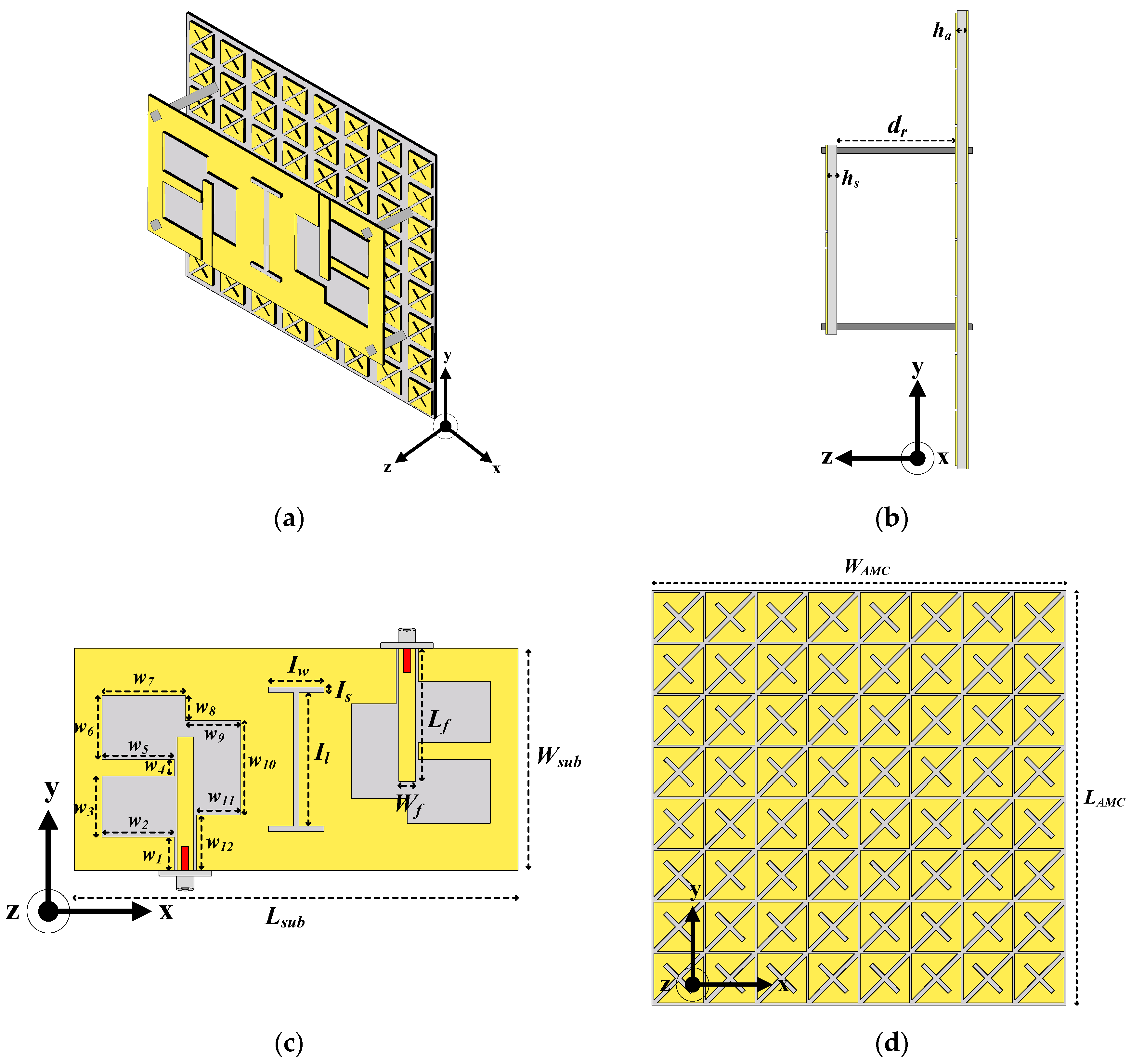
Figure 1. The proposed dual-element wideband CP slot-integrated MIMO antenna with X-notch square AMC: (a) schematic view, (b) side view, (c) upper-layer substrate (MIMO antenna), and (d) lower-layer substrate (reflector).
Technologies 13 00367 g001
Figure 2. Three layouts of the single-element slot-integrated antenna scheme: (a) first layout, (b) second layout, and (c) third layout.
Technologies 13 00367 g002
Figure 3. CMA results of the first layout of the single-element slot-integrated antenna: (a) modal significance showing modes J3 and J4 with 0.88 at 5.6 GHz, giving rise to resonant frequency, (b) phase difference of characteristic angle showing modes J3 and J4 with 55°, indicating non-CP radiation, (c) current distribution showing non-orthogonal direction, resulting in non-CP radiation, and (d) radiation patterns showing non-symmetrical main lobe, failing to achieve CP radiation.
Technologies 13 00367 g003
Figure 4. CMA results of the second layout of the single-element slot-integrated antenna scheme: (a) modal significance showing modes J3 and J6 with 0.91 at 6.1 GHz, giving rise to resonant frequency, (b) phase difference of characteristic angle showing modes J3 and J6 with 67°, indicating non-CP radiation, (c) current distribution showing non-orthogonal direction, resulting in non-CP radiation, and (d) radiation pattern showing modes J3 with null-radiation at the main lobe, failing to achieve CP radiation.
Technologies 13 00367 g004
Figure 5. CMA results of the third layout of the single-element slot-integrated antenna scheme: (a) modal significance showing modes J5 and J6 with 0.92 at 5.9 GHz, giving rise to resonant frequency, (b) phase difference of characteristic angle showing modes J5 and J6 with 82°, indicating potential for CP radiation, (c) current distribution showing orthogonal direction, indicating CP radiation, and (d) radiation pattern showing modes J5 and J6 with symmetrical lobes and orthogonality, resulting in CP radiation.
Technologies 13 00367 g005
Figure 6. Simulated results of three layouts of the single-element slot-integrated antenna: (a) RLBW, (b) ARBW, and (c) gain.
Technologies 13 00367 g006
Figure 7. Simulated results of third layout under different ratios W4:W5: (a) RLBW and (b) ARBW.
Technologies 13 00367 g007
Figure 8. Simulated results of the third layout under different ratios W8:W9: (a) RLBW and (b) ARBW.
Technologies 13 00367 g008
Figure 9. Current distribution of the dual-element antenna at 5.5 GHz under various configurations: (a) parallel configuration, (b) orthogonal configuration, (c) opposite configuration, and (d) opposite configuration with I-shaped slot DGS isolator.
Technologies 13 00367 g009
Figure 10. Simulated electric field magnitude in the XY-plane at 5.5 GHz.
Technologies 13 00367 g010
Figure 11. Simulated results for various dual-element antenna configurations: (a) RLBW, (b) isolation, (c) ARBW, and (d) gain.
Technologies 13 00367 g011
Figure 12. X-notch square elemental unit: (a) configuration, (b) boundary setup, and (c) equivalent circuit model.
Technologies 13 00367 g012
Figure 13. Simulated reflection phase of an X-notch square elemental unit for various parameters: (a) tilting angle of minor-diagonal arm, (b) length of minor-diagonal arm, and (c) arm width.
Technologies 13 00367 g013
Figure 14. X-notch square elemental unit: (a) boundary setup and (b) dispersion diagram.
Technologies 13 00367 g014
Figure 15. Simulated results of the proposed antenna scheme for different distances between the antenna and the AMC reflector: (a) RLBW, (b) isolation, (c) ARBW, and (d) gain.
Technologies 13 00367 g015
Figure 16. Simulated results of the proposed antenna scheme for different numbers of X-notch square element units: (a) RLBW, (b) isolation, (c) ARBW, and (d) gain.
Technologies 13 00367 g016
Figure 17. Antenna prototype: (a) dual-element slot-integrated MIMO antenna, (b) dual-element slot-integrated MIMO antenna with AMC reflector, and (c) experimental setup.
Technologies 13 00367 g017
Figure 18. Simulated and measured results of the proposed antenna scheme: (a) RLBW, (b) isolation, (c) ARBW, and (d) gain.
Technologies 13 00367 g018
Figure 19. Simulated and measured radiation patterns of the proposed dual-element antenna scheme at (a) 5.4 GHz (element 1), (b) 5.4 GHz (element 2), (c) 5.9 GHz (element 1), and (d) 5.9 GHz (element 2).
Technologies 13 00367 g019
Figure 20. Simulated and measured ECC of the proposed dual-element antenna scheme.
Technologies 13 00367 g020
Figure 21. Simulated and measured diversity gain of the proposed dual-element antenna scheme.
Technologies 13 00367 g021
Table 1. The optimal dimensions of the proposed antenna scheme.
ParametersLsubWsubWAMCLAMCW1W2W3
Values (mm)804092.592.561311
ParametersW4W5W6W7W8W9W10
Values (mm)31311.5154.51017
ParametersW11W12IwIsIlWfLf
Values (mm)81010124324
ParametersWaPaLnLmθngxgs
Values (mm)12115.515.0645°0.50.5
Parametershahsdr
Values (mm)1.61.636
Table 2. Comparison results of three layouts.
LayoutsGeometry ChangeCMA ResultsRLBW
(GHz)
ARRW
(GHz)
Max. Gain
(dBic)
MSPhase Diff. of CACurrent DistributionRadiation Pattern
FirstSquare copper plate (PEC) with asymmetric square slotModes J3 and J4 with 0.88 at 5.6 GHz55°Non-orthogonal directionNon-symmetrical main lobe4.93–6.685.56–5.742.46
at 5.3 GHz
SecondRectangular stub at the right corner of the slot ground planeModes J3 and J6 with 0.91 at 6.1 GHz67°Non-orthogonal directionModes J3 with null-radiation at the main lobe4.63–6.775.81–6.761.38
at 6 GHz
ThirdStrip-line stub at the center-left of the slot ground planeModes J5 and J6 with 0.92 at 5.9 GHz82°Orthogonal directionCP radiation4.7–6.955.19–6.533.51
at 5.6 GHz
Table 3. Performance comparison between existing MIMO antennas with a reflector and the proposed dual-element CP slot-integrated MIMO antenna with an X-notch square AMC.
Ref.Antenna TypeOperating
Frequency
(GHz)
Center
Frequency
(GHz)
|S11|
(%)
Isolation
(dB)
ARBW
(%)
Max.
Gain
(dBic)
ECCFabrication ComplexityCost/InstallationOverall Physical Size
(mm3)
Overall
Electrical Size
3)
[14]Slot-integrated MIMO antenna with PEC reflector2.9–7.1382>2268.56<0.003LowHigh
(Rogers RO4003)
99.73 × 33.50 × 21.401.78 × 0.59 × 0.55
[36]Slot-integrated MIMO antenna with circular-slot square FSS3–63.585.71>13N/A7.96<0.004LowLow
(FR-4)
221.00 × 179.00 × 56.002.21 × 1.79 × 0.56
[37]Slot-integrated MIMO antenna with coplanar ground and PEC reflector4.5–6.74.539.3>1539.35.8<0.005LowHigh
(Rogers 4350B)
117.50 × 94.90 × 30.001.62 × 1.14 × 0.47
[38]CPW-fed MIMO antenna with PEC reflector5.2–6.35.218.3>2218.35.8<0.004LowHigh
(Rogers RO4003)
99.70 × 33.50 × 0.811.16 × 0.43 × 0.44
[39]Microstrip-line feeding MIMO antenna with DGS and metasurface reflector2.36–2.5
3.43–3.5
5.15–5.88
2.46
3.51
5.31
5.76
2.02
13.22
>17
>18
>32
N/A5.49
4.57
0.8
<0.03
<0.035
<0.005
LowLow
(FR-4)
52.00 × 36.70 × 1.501.37 × 1.37 × 0.21
This workSlot-integrated MIMO antenna with X-notch square AMC4.72–6.615.932>1921.188.6<0.003LowLow
(FR-4)
92.50 × 92.50 × 39.202.87 × 2.87 × 1.17
λ represents the free-space wavelength at the lowest operating frequency. Center frequency refers to the nominal application/service center.
Disclaimer/Publisher’s Note: The statements, opinions and data contained in all publications are solely those of the individual author(s) and contributor(s) and not of MDPI and/or the editor(s). MDPI and/or the editor(s) disclaim responsibility for any injury to people or property resulting from any ideas, methods, instructions or products referred to in the content.