Article

Structural Design of a Multi-Stage Variable Stiffness Manipulator Based on Low-Melting-Point Alloys

1
School of Mechanical Engineering and Automation, Fuzhou University, Fuzhou 350108, China
2
State Key Laboratory of Robotics and System, Harbin Institute of Technology, Harbin 150001, China
*
Author to whom correspondence should be addressed.
Technologies 2025, 13(8), 338; https://doi.org/10.3390/technologies13080338
Submission received: 27 June 2025 / Revised: 26 July 2025 / Accepted: 28 July 2025 / Published: 5 August 2025

Abstract

Soft manipulators have garnered significant research attention in recent years due to their flexibility and adaptability. However, the inherent flexibility of these manipulators imposes limitations on their load-bearing capacity and stability. To address this, this study compares various variable stiffness technologies and proposes a novel design concept: leveraging the phase-change characteristics of low-melting-point alloys (LMPAs) with distinct melting points to fulfill the variable stiffness requirements of soft manipulators. The pneumatic structure of the manipulator is fabricated via 3D-printed molds and silicone casting. The manipulator integrates a pneumatic working chamber, variable stiffness chambers, heating devices, sensors, and a central channel, achieving multi-stage variable stiffness through controlled heating of the LMPAs. A steady-state temperature field distribution model is established based on the integral form of Fourier’s law, complemented by finite element analysis (FEA). Subsequently, the operational temperatures at which the variable stiffness mechanism activates, and the bending performance are experimentally validated. Finally, stiffness characterization and kinematic performance experiments are conducted to evaluate the manipulator’s variable stiffness capabilities and flexibility. This design enables the manipulator to switch among low, medium, and high stiffness levels, balancing flexibility and stability, and provides a new paradigm for the design of soft manipulators.

1. Introduction

Soft robotics is a rapidly growing field that leverages the mechanical properties of soft materials to address unresolved challenges in traditional robotics [1,2]. Compared to traditional robots, soft robots are valued for their flexibility and intrinsic mechanical compliance, which allow them to adapt to complex environments with minimal risk of damage. They can navigate around obstacles and traverse confined or tortuous paths [3], enabling functionalities such as biomimetic motion [4,5] and grasping [6]. However, the inherently low stiffness of soft robotic systems limits their performance in tasks that require higher load capacities, such as grasping and surgical procedures [7]. Often, soft robotic systems—particularly soft manipulators—aim to achieve high load capacity during load-bearing tasks without sacrificing compliance during object interaction [8]. Many soft robotic grippers can undergo large deformations but maintain constant bending stiffness throughout their range of motion [9]. Therefore, variable stiffness technologies represent a critical milestone in the development of soft robotics [10].
Several reviews have highlighted researchers’ efforts in developing variable stiffness actuators and structures [11,12,13]. Researchers developed a variable stiffness soft robotic manipulator using granular or particle jamming, supported by the FP7 STIFF-FLOP project [14,15,16]. By embedding a granular jamming mechanism at the center of the module and combining it with fluidic actuation, a MIS robot was designed that could control the interactions with structures by changing the stiffness of selected modules on the robot [17]. In subsequent studies, researchers have increasingly explored using layered structures instead of particles in soft actuators. These systems use pneumatic or electrostatic forces to modulate interlayer friction, enabling variable stiffness [18,19,20]. Both granular/particle jamming and layer jamming require a substantial volume of material to achieve noticeable stiffness variation. Furthermore, they are still limited in achieving large stiffness variation. Another approach is the antagonistic method, in which researchers combine different active actuation technologies to develop design principles for variable stiffness robotic manipulators. One example of such a variable stiffness manipulator involves tendons coupled with a pneumatic extension actuator [21,22,23]. However, the antagonistic actuators must remain both active and coupled to each other. This would increase the difficulty of variable stiffness and position decoupling [24]. Recently, researchers have proposed other notable variable stiffness systems using stiffness-tunable materials to support various design strategies or robotic applications [13,25,26]. Some researchers have introduced polymers in the design of soft robotic manipulators to achieve variable stiffness [27,28]. The heating process of polymers requires numerous heating elements and complex control systems, making it challenging to achieve uniform heating across large areas or volumetric structures.
Compared to these methods, low-melting-point alloys (LMPAs) have large stiffness variation intervals. LMPAs require minimal volume in applications and offer significant advantages in control. Additionally, self-healing can be intrinsically achieved through the re-crystallization of the alloy [29]. In recent years, LMPAs have attracted significant attention as a novel method for enhancing the performance of soft manipulators. Alambeigi et al. demonstrated a cable-driven continuum manipulator incorporating a low-melting-point phase-change alloy (melting point 62 °C). They proposed a method for locally adjusting the manipulator’s stiffness using targeted selective heating [24], offering a promising approach to stiffness control based on phase-change materials. Although this approach enabled the modulation of shear stiffness, it did not achieve multi-stage stiffness variation. Pagliarani et al. developed a variable stiffness manipulator combining LMPAs with fiber jamming. However, this approach increased the complexity of both control and structural design [10].
Three-dimensional (3D) printing enables the layer-by-layer fabrication of physical objects by depositing materials based on computer-aided design and manufacturing instruction [30]. A common fabrication approach involves 3D printing custom molds, followed by the casting of flexible elastomeric materials. This technique remains well-suited for constructing soft robots with relatively simple internal architectures [31]. Ang et al. developed a 3D-printed soft pneumatic gripper utilizing a folding-based structure. By varying the folding dimensions and adjusting the position of the strain-limiting layer, the actuator can achieve different bending angles [32]. Tawk et al. introduced a tendon-driven soft gripper with three fingers, in which 3D-printed linear soft vacuum actuators are used to actuate the tendons [33].
Recent advances in deep learning and cognitive computing have significantly contributed to various fields, providing novel frameworks for intelligent modeling, feedback control, and adaptive decision-making. For example, comprehensive reviews on medical image segmentation [34] and flow prediction in flexible structures using cognitive computing [35] illustrate how data-driven methods enhance system performance in complex environments. While these works focus on biomedical imaging and fluid dynamics, their underlying principles—such as real-time feedback integration, model optimization, and dynamic system adaptation—are highly relevant to the development of intelligent soft robotic systems. These interdisciplinary insights underscore the potential for future integration of intelligent control algorithms and sensing technologies into soft manipulators, especially for closed-loop stiffness regulation and environmental adaptation.
To sum up, considering the limitations of soft manipulators with different stiffness-adjusting mechanisms, and inspired by the LMPAs’ stiffness-adjusting mechanism, we hope to achieve variable stiffness of soft manipulator through combined use of LMPAs with different melting points. Therefore, this study proposes a novel soft manipulator design concept. An efficient control system is developed, enabling the manipulator to achieve multi-stage stiffness adjustment across three levels: low, medium, and high. The manipulator retains high flexibility due to its soft materials, while the enhanced stiffness enables stable positioning and load-bearing capabilities. The manipulator can better adapt to different working environments and task requirements by its variable stiffness.
The novelty and contributions of the proposed manipulator can be summarized as follows: (1) While the concept of LMPA-based variable stiffness has been independently explored, this is, to the best of our knowledge, the first study to achieve multi-stage stiffness modulation in a soft manipulator by combining LMPAs with different melting points. (2) The proposed manipulator integrates LMPAs with melting points of 47 °C and 70 °C, along with an air-driven workspace, heating elements, sensors, and a central channel, forming a novel and multifunctional device. (3) The viability of the proposed soft manipulator is validated through simulations and experiments, demonstrating excellent performance in both flexibility and stiffness characteristics.

2. Materials and Methods

2.1. Selection of LMPAs

LMPAs are predominantly constituted of elements including indium (In), bismuth (Bi), tin (Sn), cadmium (Cd), and lead (Pb). Compared to other materials such as paraffin wax and thermoplastics, LMPAs exhibit a higher elastic modulus in the solid state. Moreover, LMPAs exhibit high thermal conductivity and rapid heat transfer, which enhance the response speed of variable stiffness. Considering economic factors, safety concerns, and the requirement for multi-stage variable stiffness, two types of LMPAs with distinct melting points are selected to construct the variable stiffness chambers of the manipulator. The melting points of the selected LMPAs are 47 °C and 70 °C, respectively. These LMPAs not only meet the requirements for multi-stage variable stiffness but also enhance the manipulator’s stiffness modulation performance. The composition ratios and performance parameters of LMPAs with different melting points are presented in Table 1 [36].

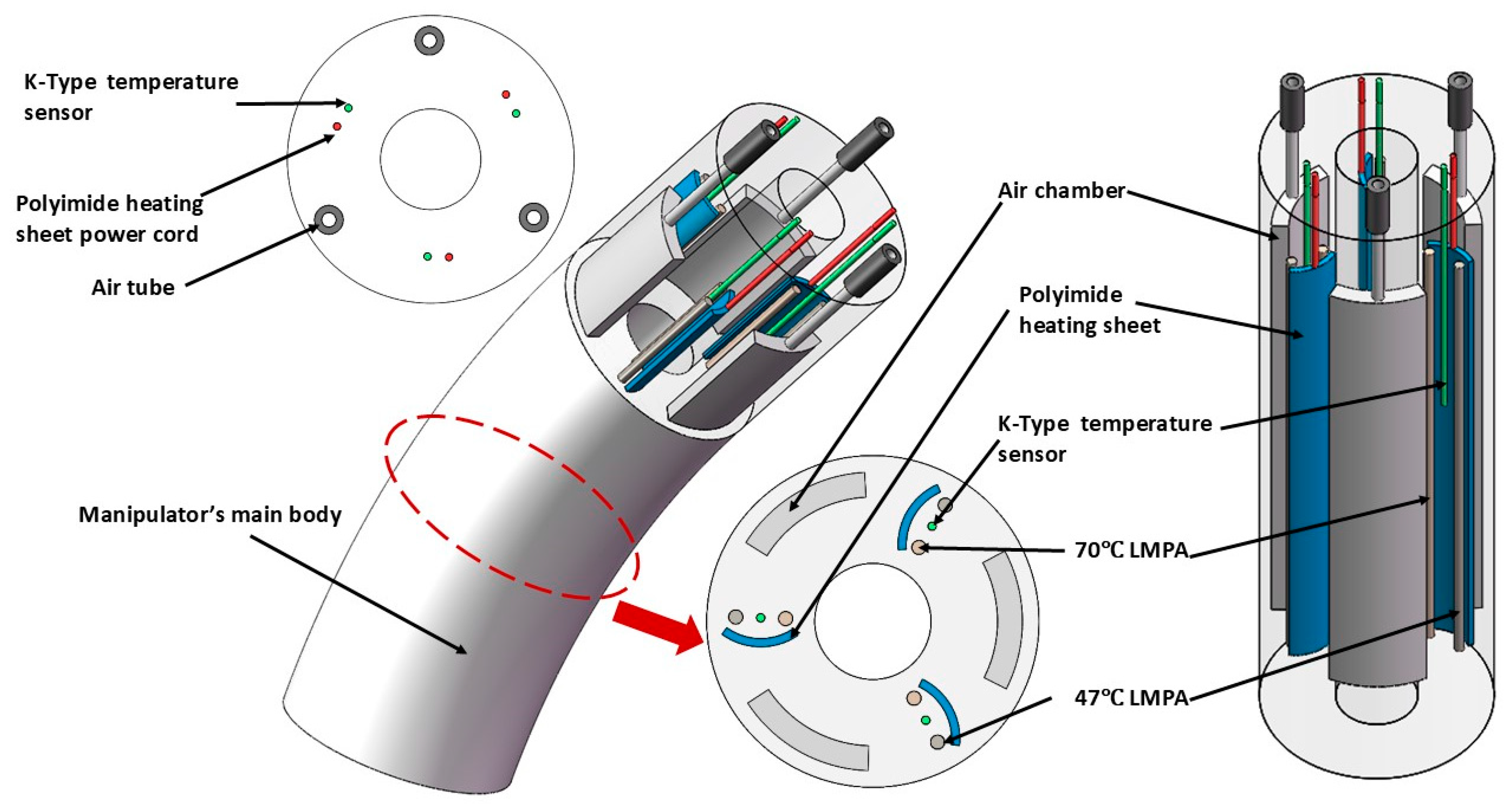
2.2. Design Concept and Structure of the Manipulator

The design concept of the proposed manipulator is depicted in Figure 1. The main body of the manipulator is made of silicone rubber and includes internal air chambers, embedded K-type temperature sensors, polyimide (PI) heating sheets, LMPA chambers, and other components. The structural parameters of the proposed manipulator are summarized in Table 2. The manipulator features a cylindrical design. Its basic structure consists of three equally spaced air chambers and a central cylindrical channel for the subsequent integration of sensors or a flexible gripper. The LMPAs, with melting points of 47   ° C and 70   ° C , are arranged radially at 120 ° intervals and embedded within the manipulator. The LMPA with a melting point of 70 °C is more brittle than the one with a melting point of 47 °C and is therefore strategically positioned on the inner side. The manipulator employs built-in polyimide heating sheets to heat the variable stiffness chambers, adjusting stiffness by controlling the melting and solidification states of the LMPAs, thereby achieving multi-stage stiffness modulation. K-type temperature sensors are placed between the two variable stiffness chambers to monitor LMPA temperature during the heating process, ensuring proper phase transitions.

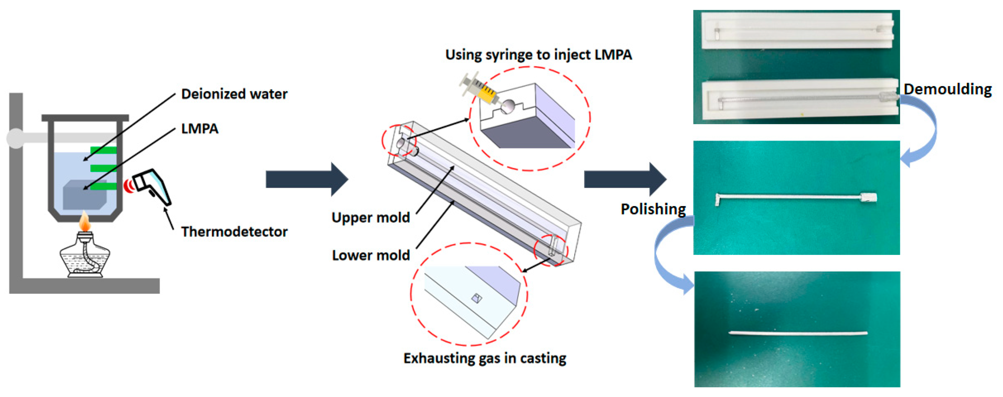
2.3. Fabrication Method of LMPA

The low-melting-point alloys molds were fabricated using a fused deposition modeling (FDM) 3D printer. Polylactic acid (PLA) filament (eSUN eLastic, Shenzhen eSUN Industrial Co., Ltd., Shenzhen, China) was used as the printing material. The 3D printer used was the R6-X6 model by JiaZhi United Technology Co., Ltd. (Guangzhou, China), a commercial desktop system equipped with open-source software for slicing STL files and generating 3D printing data. The printing parameters were set as follows: a travel speed of 60 mm/s, a build platform temperature of 50 °C, and a nozzle temperature of 220 °C.
The primary LMPA preparation process is shown in Figure 2. LMPAs are typically prepared using a casting method. For clarity, the main fabrication steps are summarized as follows.
1.
First, the LMPAs are immersed in a beaker containing deionized water and heated to achieve a molten state. In the molten state, the LMPAs exhibit a higher density and are immiscible with deionized water, resulting in stratification and settling at the bottom.
2.
Molds fabricated via 3D printing are used for casting the LMPAs. To accommodate the self-healing properties of the LMPAs during operation, the diameter of the mold cavity is designed to be slightly larger than the target dimensions of the final LMPA components. The molten LMPA is extracted using a syringe and promptly injected into the mold, allowing it to solidify at room temperature for 2–4 h.
3.
After the curing step is completed, demolding is performed to obtain the preliminary LMPA. At this stage, the LMPA does not yet meet the application requirements. The LMPA is subjected to a polishing process to achieve the desired dimensions, resulting in a final diameter of 1.8 mm.

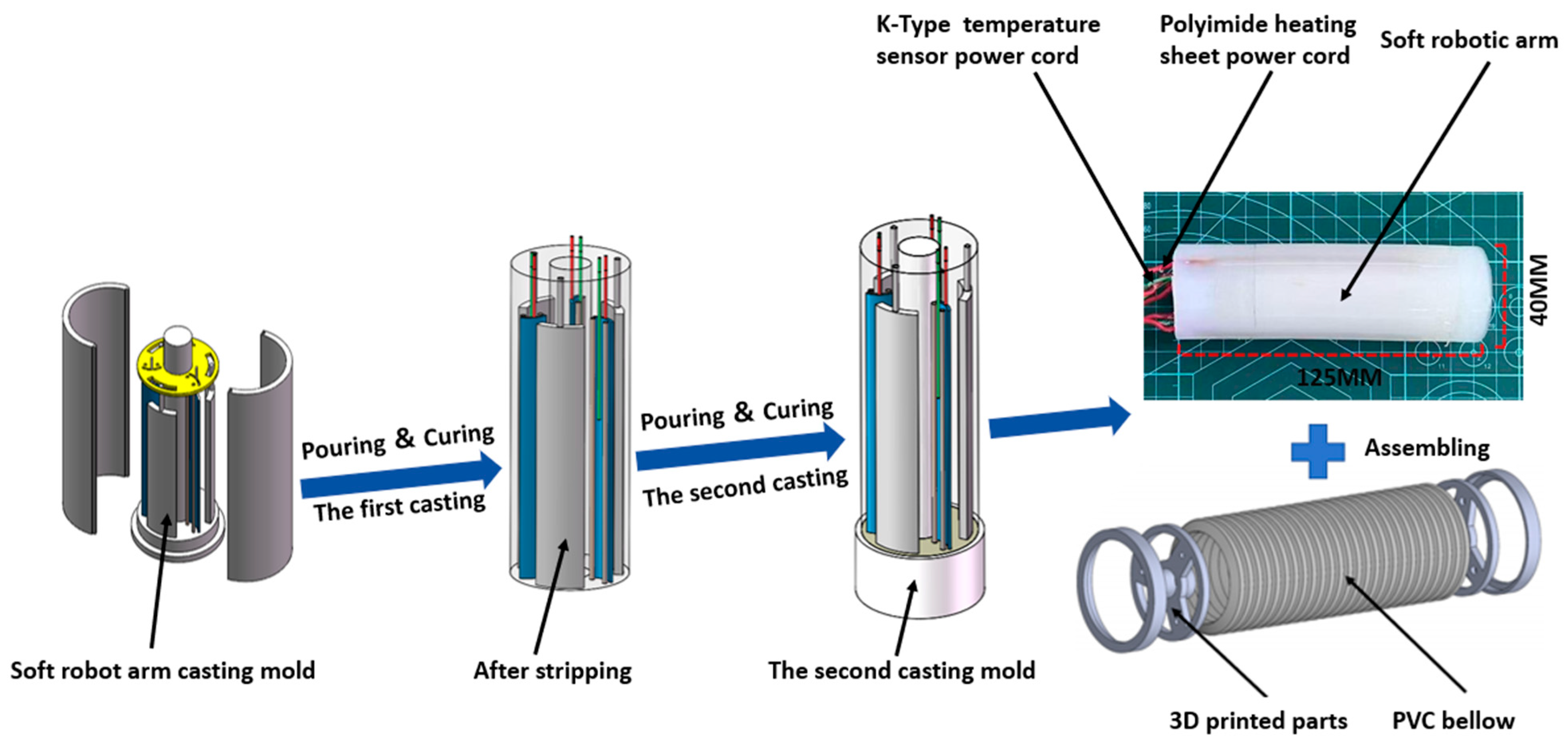
2.4. Fabrication Process of the Manipulator

With advancements in manufacturing technologies, including 3D printing, shape deposition manufacturing, and soft lithography, the fabrication of soft robots has also made significant progress. However, 3D printing can only process a limited range of soft materials. Soft lithography also faces challenges in fabricating soft robots with complex internal cavities. The proposed manipulator contains multiple enclosed cavities, rendering these methods unsuitable for fabricating its complex internal structure. Therefore, the manipulator is fabricated using a silicone rubber casting method, which is simple and cost-effective. As shown in Figure 3, the detailed fabrication process of the manipulator consists of the following steps.
1.
Nylon material, which has higher material strength, is selected as the 3D printing material for mold fabrication, followed by mold assembly. Due to the dimensional constraints of the manipulator, molds printed with PLA suffer from low precision, whereas nylon effectively overcomes this limitation.
2.
The main body of the manipulator is fabricated from silicone rubber (SJ3211, Shore hardness 15A). The silicone rubber is prepared by mixing components A and B in a 1:1 weight ratio. The mixture is stirred manually for 2–3 min and then placed in a vacuum chamber for 2 min to remove air bubbles. The degassed silicone rubber is then poured into the mold to complete the first casting step.
3.
The first casting is cured at room temperature for 6 h before being demolded. The first casting forms the manipulator’s main body, as well as the reserved chambers for built-in components and air channels. The LMPAs, K-type temperature sensors, and polyimide heating sheets are assembled into the reserved chambers. The assembled manipulator is then inverted into the mold, and the second casting step is performed by repeating the previous procedure.
4.
The second casting cures at room temperature for 6 h before being demolded. This step seals the manipulator, resulting in the formation of a fully assembled structure.
5.
Final assembly of the manipulator is performed. To limit the ballooning effect during bending, 3D-printed components are used to integrate a matching PVC bellow with the manipulator, forming the final soft robotic structure.

3. Theory and Simulation

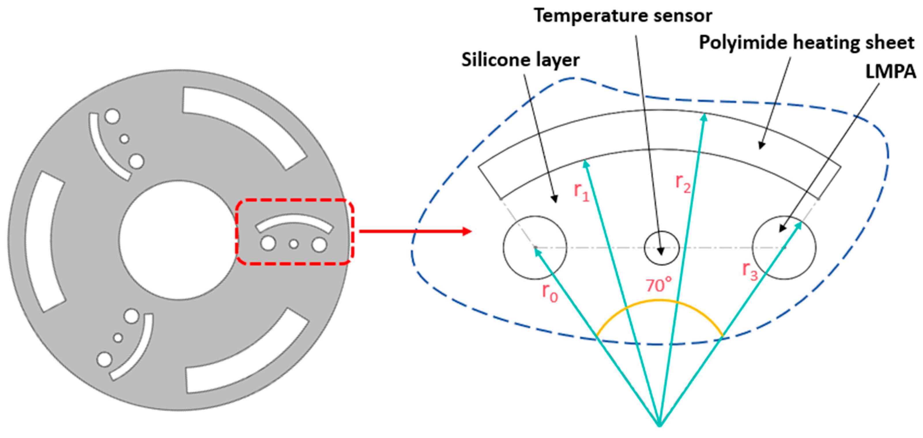
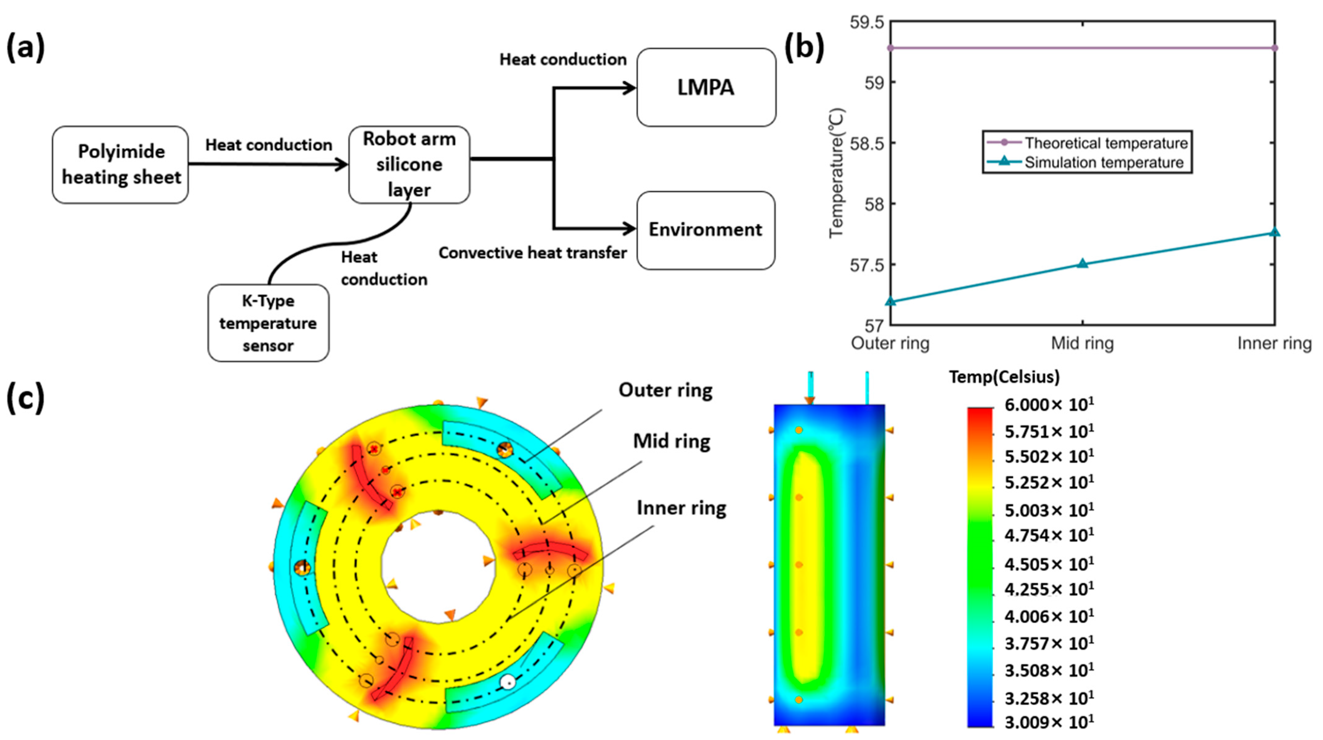
3.1. Temperature Field Model of Manipulator

In the design proposed in this study, polyimide heating sheets are used to provide heat to the LMPAs. The operating temperature range of the polyimide heating sheets spans from −40 °C to 200 °C, with a thickness of 1 mm. The use of polyimide heating sheets simplifies the fabrication process of the manipulator. To ensure accurate and reliable heat transfer during the variable stiffness process, a one-dimensional steady-state temperature field model of the manipulator is established based on Fourier’s law to approximate the temperature distribution between the polyimide heating sheets and the LMPAs.
In this model, the following simplifying assumptions are made: (1) the heat source in the semi-annular region is uniformly distributed, and (2) heat transfer occurs solely in the radial direction (one-dimensional heat conduction) [37]. First, the heat flux density per unit length along the inner circumference (at radius r = r 1 ) of the polyimide heating sheet is calculated. Assuming a uniform heat source distribution in the polyimide heating sheet, the heat flux per unit length at the boundary r = r 1 is given by
q l e n g t h = 70 360 × P π ( r 2 2 r 1 2 ) × ( r 2 r 1 )
where P is the heating power of the polyimide heating sheet, with a value of 60 W; r 1   is the inner radius of the polyimide heating sheet, equal to 7 mm; and r 2 is the outer radius, equal to 8 mm. Neglecting axial heat conduction and applying the integral form of Fourier’s law, a one-dimensional steady-state heat conduction equation can be established:
1 r d d r ( r d T d r ) = 0
To solve the one-dimensional steady-state heat conduction problem, the model is defined with both Dirichlet and Neumann boundary conditions: the boundary of the polyimide heating sheet is isothermal, and the heat flux density is applied to the silicone layer; at the contact surface between the silicone rubber layer and the variable stiffness layer, both temperature and heat flux density are continuous. The boundary conditions for the one-dimensional steady-state heat conduction equation are generally defined as follows
T 0 = T r 1 k 1 d T d r r = r 1 = q l e n g t h T r 3 + = T r 3 k 1 d T d r r = r 3 = k 2 d T d r r = r 3 +
where   k 1 is the thermal conductivity of the silicone rubber layer, equal to 0.26 W / ( m K ) , k 2 is the thermal conductivity of the variable stiffness layer, equal to 20.26 W / ( m K ) , r 1 and r 2 are shown in Figure 4,   r 1   is 5.5 mm and   r 2   is 6.3 mm. Based on the aforementioned boundary conditions and the integral form of Fourier’s law, Equation (4) is derived, and the temperature at the center of the variable stiffness layer is calculated to be 59.28 °C.
T = T 0 ( q l e n g t h r 1 k 1 ) ln ( r 3 r 1 ) k 1 k 2 ( q l e n g t h r 1 k 1 ) ln ( r 0 r 3 )

3.2. Steady-State Thermodynamic Simulation of the Model

To verify the theoretical model of the one-dimensional steady-state temperature distribution, a corresponding thermodynamic simulation is conducted. These simulations aim to evaluate the temperature field and assess the applicability and limitations of the analytical model under idealized assumptions. The heat conduction modes for different regions of the manipulator are illustrated in Figure 5a. Thermodynamic simulations were conducted using the SolidWorks Flow Simulation module (version 2022), a commercially adopted CAD-integrated FEA tool suitable for steady-state thermal analysis in multi-material structures. The following parameters were defined: the convective heat transfer coefficient   h k , representing natural convection at both the outer surface and internal cavity walls, is set to 10 W / ( m 2 K ) ; the silicone rubber layer has a thermal conductivity of 0.26 W / ( m K ) , a constant-pressure heat capacity of 1285   J / ( k g K ) , and a density of 1200 k g / m 3 ; the LMPA layer has a thermal conductivity of 20.26 W / ( m K ) , a constant-pressure heat capacity of 180 J / ( k g K ) , and a density of 8774   k g / m 3 . A temperature boundary condition of 60 °C was applied to the surface of the polyimide heating sheet. The computational domain was discretized using an unstructured tetrahedral mesh. Mesh quality was automatically optimized based on geometry curvature and thermal gradients.
The resulting temperature distribution near the sheet is shown in Figure 5c. The temperatures obtained from both thermodynamic simulation and theoretical calculation are presented in Figure 5b. Due to the simplifications inherent in the one-dimensional steady-state temperature model, a discrepancy exists between the simulated and theoretical temperatures, with a maximum error of approximately 2 °C. The simulation results indicate that when the polyimide heating sheet reaches 60 °C, the temperature difference between the variable stiffness layers does not exceed 0.6 °C. Additionally, in the thermodynamic simulation, the temperatures measured by the K-type temperature sensors differ from the variable stiffness layers by 0.3 °C. The K-type temperature sensors accurately monitor the heating temperature of the variable stiffness layers, ensuring that the LMPAs reach a molten state to meet the stiffness modulation requirements.

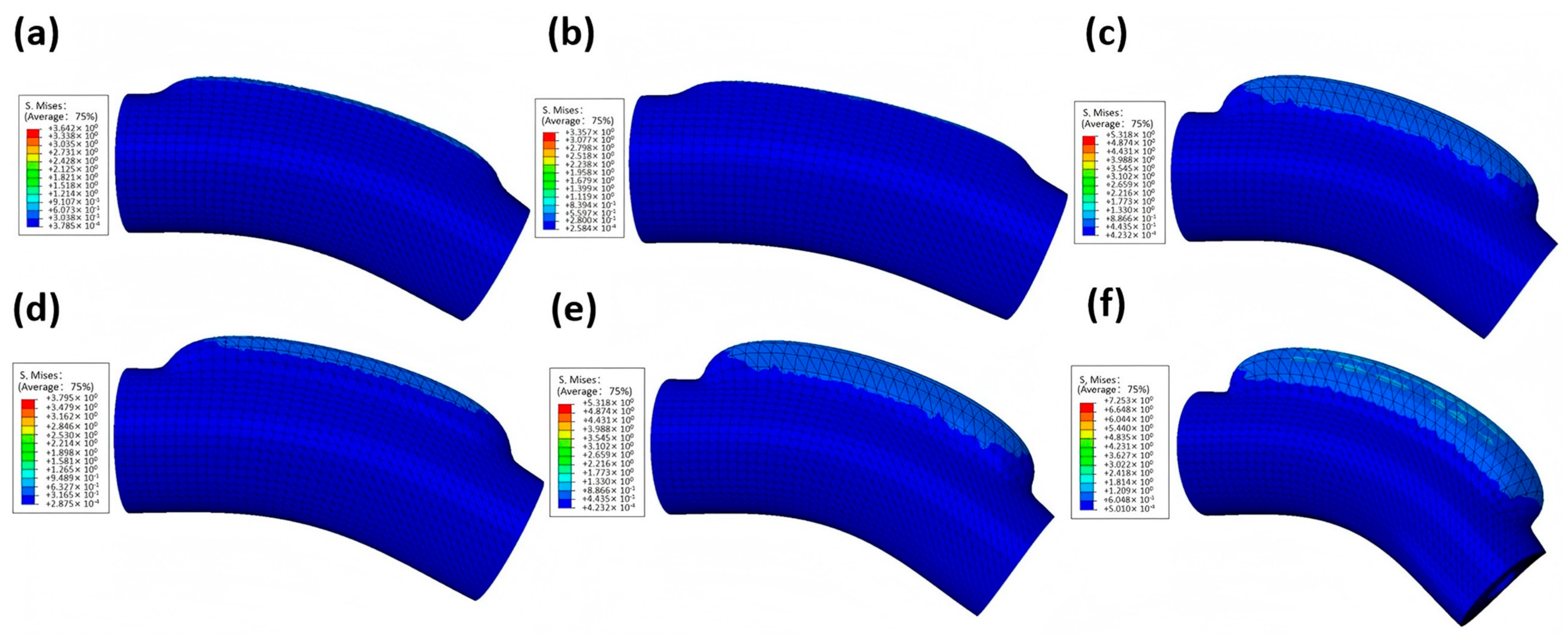
3.3. Air-Driven Simulation of the Manipulator

To evaluate the flexibility of the soft manipulator, finite element simulation and analysis are performed. The manipulator is actuated through pressurization of internal chambers, inducing deformation to achieve the desired motion characteristics. The ABAQUS is used for the simulation, and the material density of the silicone rubber layer is set to 1.2 × 10⁻⁹. The finite element analysis model of the soft manipulator is established using Yeoh’s third-order model, and the coefficients can be obtained through the uniaxial tensile experiment as C10 = 4.15 × 10⁻², C20 = 2.17 × 10⁻³, C30 = 6.89 × 10⁻⁴. The manipulator is discretized using a tetrahedral mesh.
In the simulation, a single chamber of the manipulator is pressurized to simulate actual inflation, with the pressure load applied to a selected chamber. Boundary conditions are defined so that the circular surface at the intake end is fixed to remain stationary. After defining the boundary conditions and loading for the entire structure, the simulation is submitted for analysis. As shown in Figure 6, the soft manipulator is able to bend as intended, and the bending angle increases with rising air pressure.
Different finite element models are designed according to the size of the wall thickness and the shape of the chamber, and the pressure and the corresponding bending angle of the soft manipulator are simulated. The wall thickness of the air chamber determines its capacity to withstand internal pressure. If the wall thickness is too small, significant ballooning may occur under pressure, leading to reduced structural stability and other issues. Conversely, if the wall thickness is too large, a much higher pressure is required to induce bending, and mechanical hysteresis may occur.
Finite element analysis is conducted on air chambers with circular, semicircular, and fan-shaped cross-sections under an applied air pressure of 60 kPa. Simulation results show that, under the same air pressure, the fan-shaped cross-section achieves greater bending. Additional finite element analyses are performed on three fan-shaped chambers with wall thicknesses of 3.5 mm, 2.5 mm, and 1.5 mm, respectively, under a constant pressure of 60 kPa. The simulation results indicate that, under constant pressure, a thinner wall thickness leads to a larger bending angle of the manipulator. However, reduced wall thickness compromises the stability of the manipulator. As shown in Figure 6, the manipulator exhibits a pronounced ballooning effect in the absence of a constraint layer. Therefore, a PVC bellow is integrated into the soft manipulator as a constraint layer.

4. Experiment Validation and Assessment

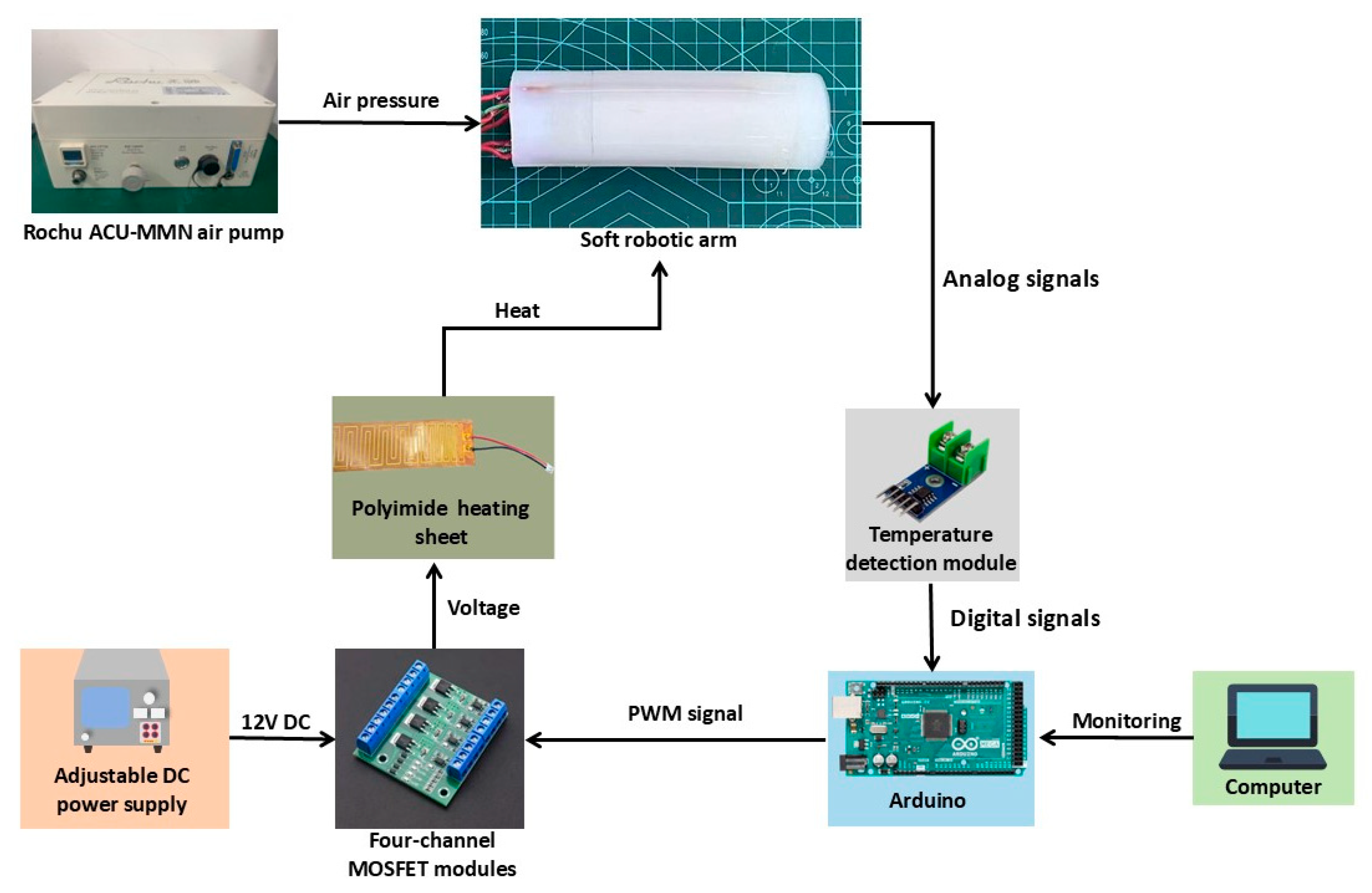
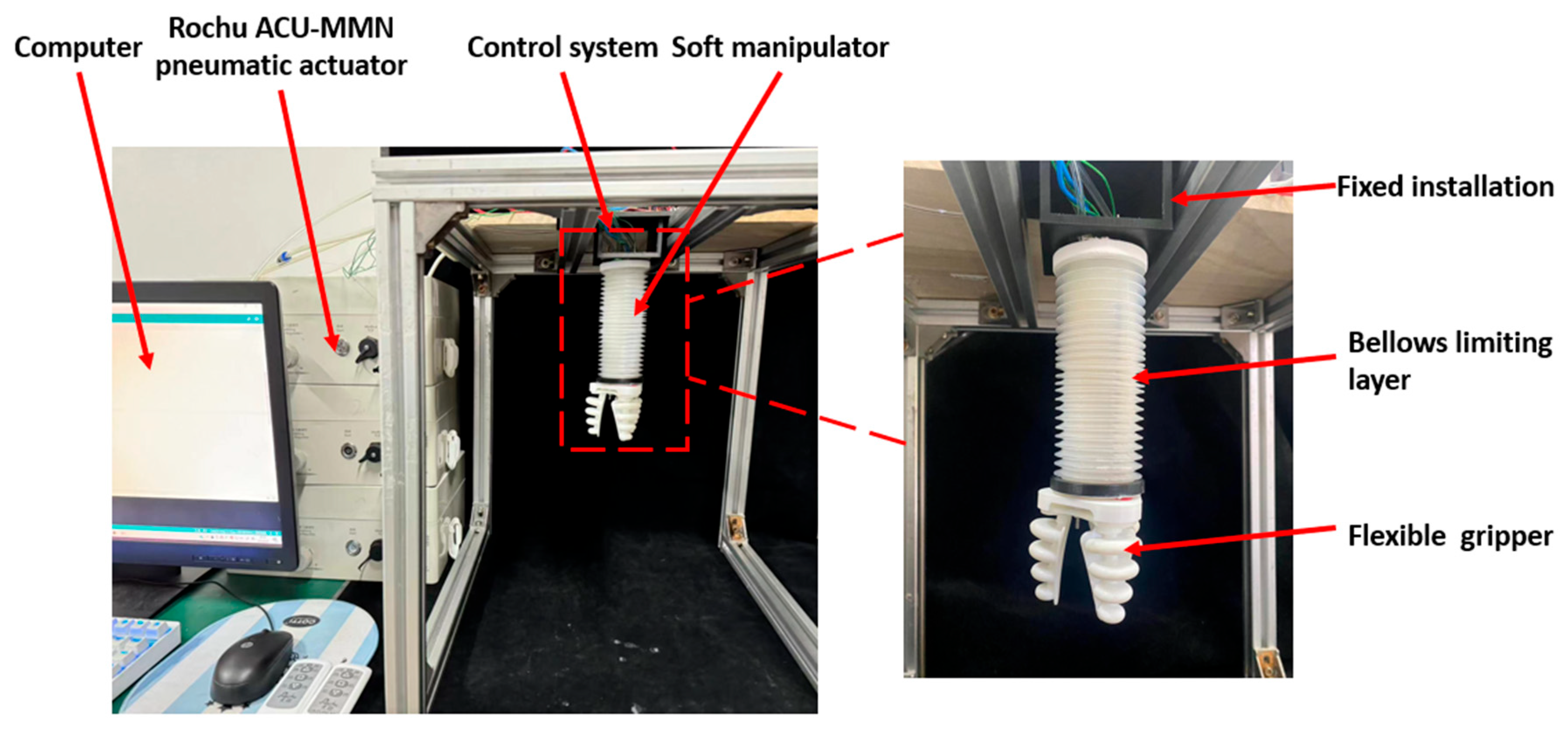
4.1. Soft Manipulator Control System

The control system of the manipulator is illustrated in Figure 7. The system employs a commercial controller board (Arduino Mega 2560 R3 (Harbin Alseon Robotics Technology Co., Ltd., Harbin, China) with 14 pulse-width modulation (PWM) outputs and 16 analog inputs), which interfaces with a host computer to provide control signals. An adjustable DC power supply (0–24 V DC, 0–5 A max) (Dongguan Bufan Electronics Co., Ltd., Dongguan, China) is used as the primary input source, which supplies power to the polyimide heating sheets. In this study, three working temperatures—23 °C, 68 °C, and 85 °C—are defined for the manipulator. Embedded K-type temperature sensors (Jinhua Longke Xin Technology Co., Ltd., Jinhua, China) generate analog millivolt-level signals proportional to temperature, which are digitized via MAX6675 signal conditioning modules for microcontroller processing. Simultaneously, the polyimide heating sheets are regulated through PWM control signals driven by four-channel MOSFET modules to reach target temperatures, enabling precise melting and solidification control of the LMPAs. Thanks to closed-loop control by the K-type temperature sensors, the manipulator’s working temperature is consistently maintained within a suitable range, ensuring appropriate LMPA phase transitions during variable stiffness activation. A pneumatic actuator (Rochu ACU-MMN, Suzhou Rochu Robotics Co., Ltd., Suzhou, China) is employed to provide air-driven actuation for the manipulator. Depending on the application scenario, the actuator can be adjusted to apply either positive or negative pressure to the manipulator.

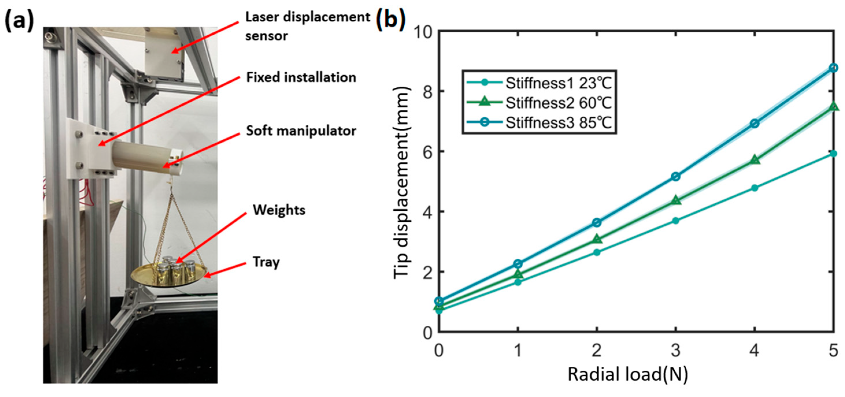
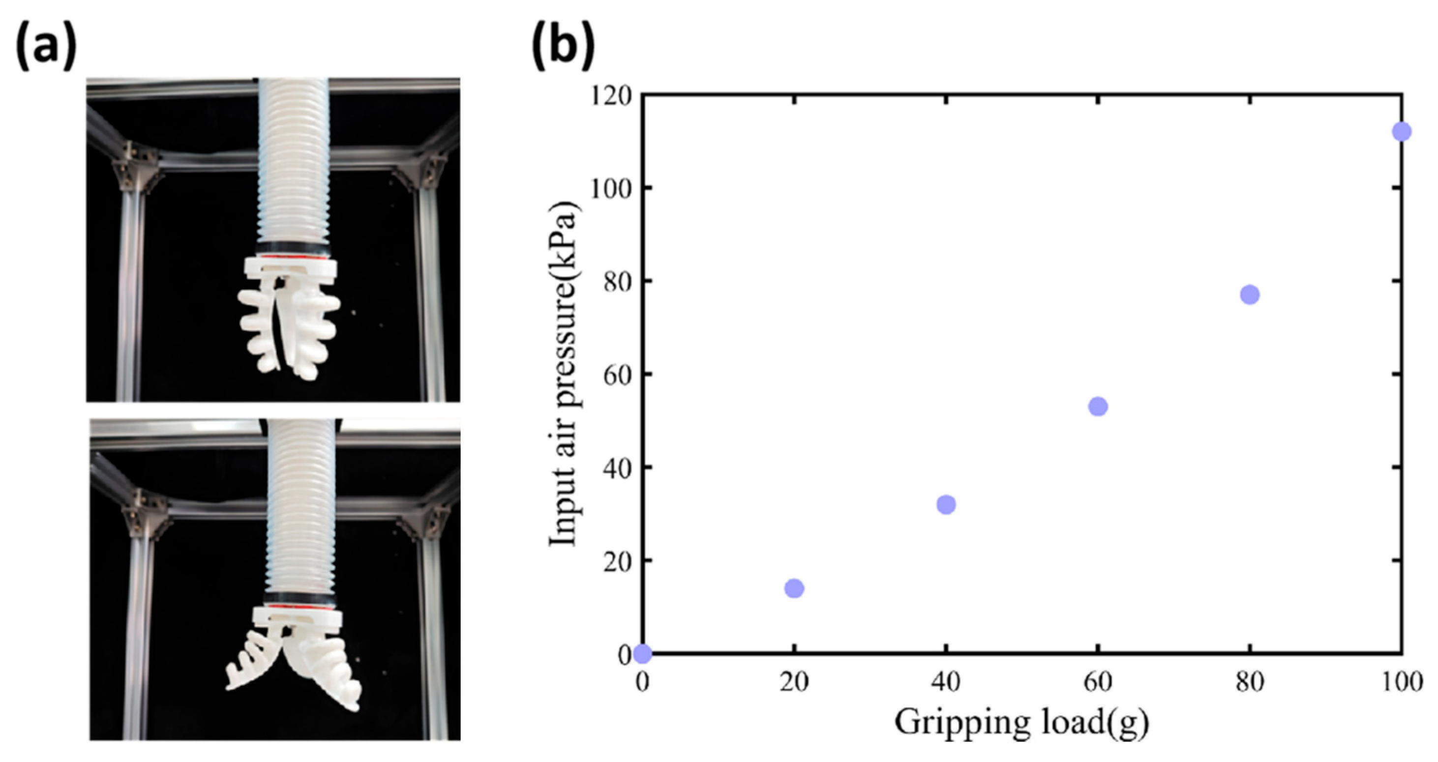
4.2. Stiffness Characterization Under Static Loading

In practical applications, flexibility alone is insufficient. The manipulator must also exhibit sufficient rigidity to resist external forces and maintain its deformed shape. Therefore, a cantilever beam bending test under static loading is conducted to evaluate the multi-stage variable stiffness capability in the static state. The experimental setup is illustrated in Figure 8a. The manipulator is secured by a 3D-printed fixed installation on a rigid aluminum pole rack and is connected to the experimental control system. The free end of the manipulator remains unconstrained, forming a configuration analogous to a cantilever beam. A laser displacement sensor (Keyence I-L100, Keyence (China) Co., Ltd., Shanghai, China) is positioned directly above the manipulator tip to record displacement data. The load is simulated by hanging weights from the manipulator tip.
In the experiment, the applied load is incrementally increased, and the corresponding load–displacement curves of the manipulator at different working temperatures are recorded, as shown in Figure 8b. A displacement of 1 mm is observed due to the manipulator’s self-weight. Under a load of 2.5 N, the displacement of the manipulator is 5.23 mm in stiffness level one (room temperature, 23 °C), 7.24 mm in stiffness level two (heated to 60 °C), and 8.82 mm in the fully flexible state (heated to 85 °C). The displacement changes corresponding to the two rigidity-to-flexibility transitions are 1.58 mm and 3.59 mm, respectively. These results demonstrate that the manipulator is capable of maintaining its shape in the rigid state, and its overall stiffness can be modulated by controlling the phase-transition state of the LMPA. It is worth noting that the 2.5 N load mentioned in the stiffness tests was used to illustrate the difference in displacement under different stiffness levels, while actual experimental data were collected up to 5 N to assess the manipulator’s performance.

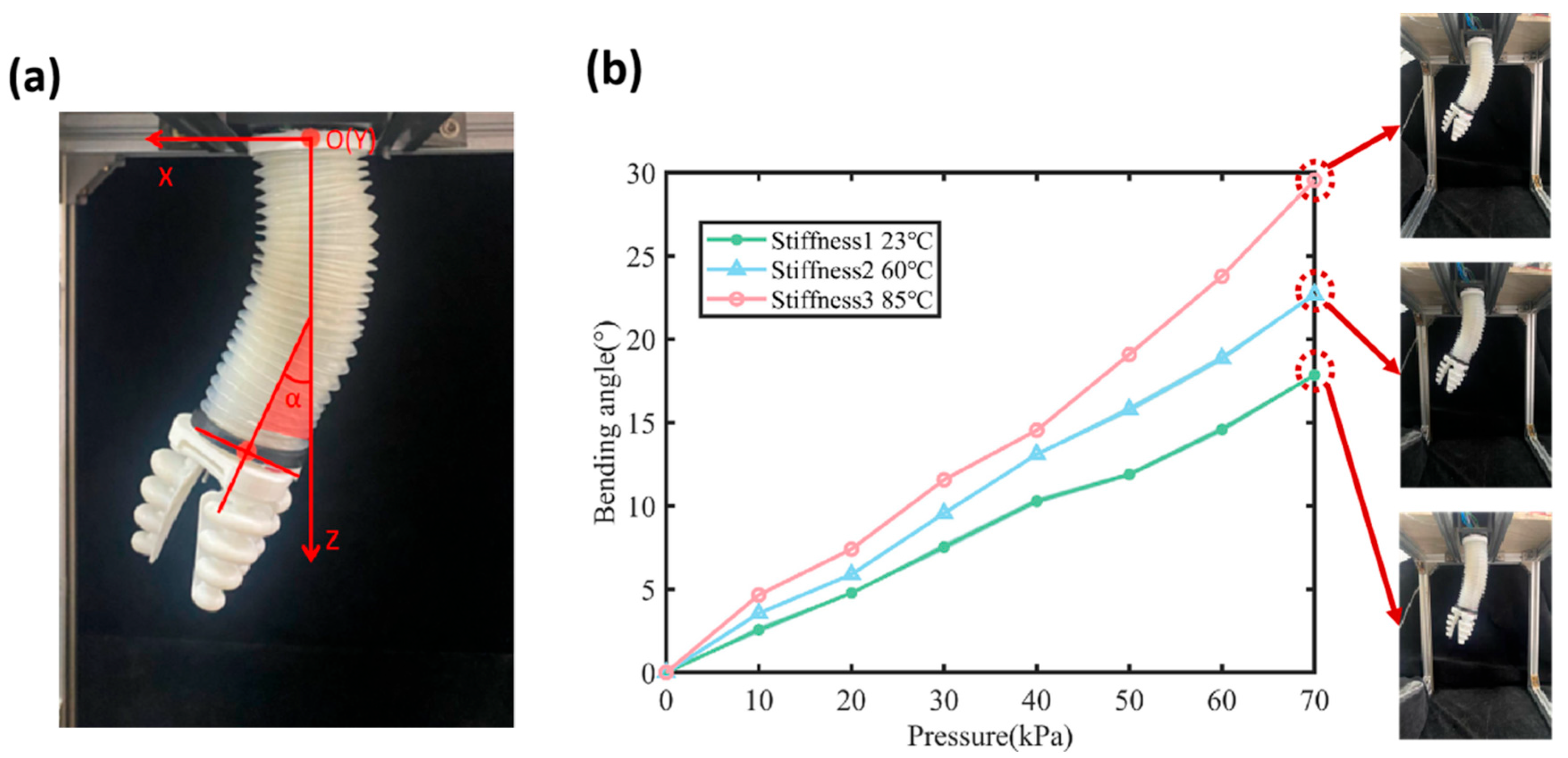
4.3. Characterization of Pneumatic Actuation Under Variable Stiffness

The multi-stage variable stiffness capabilities of the manipulator under external actuation are experimentally evaluated. The experimental setup is illustrated in Figure 9. Due to significant ballooning during inflation, an external bellows is installed around the manipulator to constrain radial expansion during pneumatic actuation, as shown in Figure 10a. The vertical downward direction of the manipulator is defined as the positive z-axis; the fixed mounting plane corresponds to the x–y plane, and the camera viewing direction aligns with the positive y-axis. To achieve planar bending motion, pressure is applied to a single air chamber using the pneumatic actuator, while the other two chambers remain unpressurized.
During the experiment, the air pressure input is adjusted from 0   k P a to 70   k P a in increments of 10   k P a using the pneumatic actuator. At each step, the center coordinates of the manipulator’s end are recorded. The digital display on the pneumatic actuator provides real-time readings of the input air pressure, which are used to determine the relationship between the planar bending angle of the manipulator and the input air pressure under different stiffness conditions. The bending angle is defined as the angle between the vertical bisector of the manipulator’s end and the positive z-axis, as illustrated in Figure 10a.
The relationship between bending angle and input air pressure under different stiffness conditions is shown in Figure 10b. Analysis of the figure indicates that, under identical air pressure conditions, an increase in heating temperature leads to a corresponding increase in the bending angle of the manipulator. At an input air pressure of 70 k P a , the bending angles at 23 °C (room temperature), 60 °C, and 85 °C are 18°, 22°, and 29°, respectively. Moreover, as the input air pressure increases, the bending angle of the manipulator exhibits a more pronounced growth trend. Specifically, higher input air pressure results in greater magnitude and range of bending angle variation. As shown in Figure 10b, for the same bending angle, the manipulator with higher stiffness requires greater input pressure compared to the fully flexible configuration. Under the same input pressure, the bending angle of the manipulator is reduced due to the multi-stage variable stiffness mechanism; however, this reduction enhances stiffness and structural stability. These results demonstrate that the multi-stage variable stiffness mechanism significantly enhances the manipulator’s resistance to bending deformation, thereby improving its adaptability to varying working conditions.

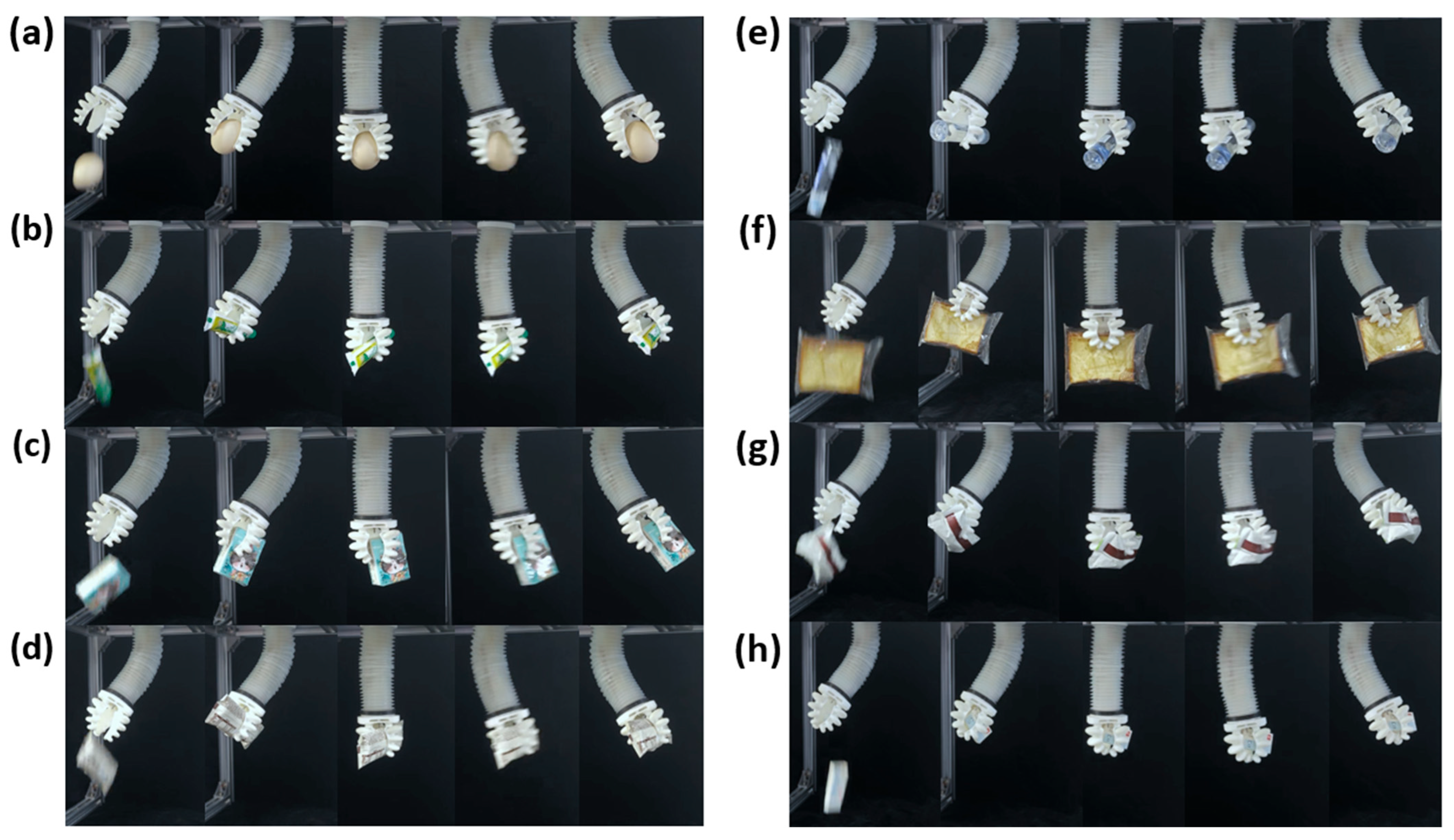
4.4. Object Grasping Experiments for Functional Verification

A three-fingered flexible gripper was fabricated using TPU 70A material (Kunshan Kangfu New Materials Co., Ltd., Suzhou, China) and printed with a Formlabs Form 3B+ SLA printer (Xinglang (Shenzhen) Technology Co., Ltd., Shenzhen, China). The gripper has a length of 50 mm, with each finger forming a 105° angle relative to the base plane. The flexible gripper opens under negative pressure and closes under positive pressure, as illustrated in Figure 11a. According to the output air pressure data on the display screen of the ACU-MMN actuator, the air pressure input into the gripper and the corresponding load are recorded at this time. By incrementally increasing the load and repeating the procedure, the relationship between input air pressure and gripping load is obtained, as shown in Figure 11b. The results show that as the load increases, the required input air pressure also rises accordingly. Due to limitations in the output capacity of the ACU-MMN actuator, the maximum load the gripper can hold within the allowable pressure range is 100 g, corresponding to an input air pressure of 114 kPa. With a more powerful pneumatic source, the gripping capacity can be further increased.
To further evaluate the manipulator’s practical applicability, a series of grasping demonstrations were conducted using eight different objects varying in shape, material, fragility, and mass. As shown in Figure 12, the tested objects include a tissue, a slice of bread, a tube of toothpaste, a box of biscuits, a bottle of liquid glue, a stapler, an egg, and a sachet of instant cereal.
The manipulator exhibits two primary grasping modes: tip-based grasping, as demonstrated with items such as the glue bottle, bread, tissue, and toothpaste; and enveloping grasping, used for objects like the egg, cereal sachet, biscuits, stapler. The results indicate that the manipulator can stably grasp fragile or deformable items (e.g., eggs, bread, tissues) without causing damage, as well as rigid and heavier objects (e.g., stapler, boxed snacks) within the system’s payload limit.
These results demonstrate the manipulator’s strong adaptability to a wide variety of objects in terms of compliance, shape, and material properties, validating its effectiveness in unstructured environments. The weight and dimensions of the tested objects are summarized in Table 3.

4.5. Response Time Assessment of LMPA Activation

In this section, experiments are conducted to evaluate the working temperature and activation time of the LMPA. Figure 13 shows the phase transition processes of LMPAs with melting points of 47 °C and 70 °C. As shown in Figure 13a, it takes 36 s to heat from room temperature to the preset working temperature of 60 °C. After reaching 60 °C, an additional 20 s of heating ensures full melting of the LMPA, enabling the soft manipulator at room temperature to achieve the first level of stiffness adjustment within 56 s. As shown in Figure 13c, approximately 105 s are required to achieve the second level of stiffness adjustment. Heating from room temperature to the preset working temperature of 85 °C takes approximately 97 s and an additional 47 s to become fully molten. The manipulator achieves full flexibility after approximately 144 s of heating, as shown in Figure 13b. In addition, the K-type temperature sensors embedded in the manipulator reflect whether the polyimide heating sheets should continue heating. As a result, once the preset working temperature is reached, the temperature exhibits an approximately sinusoidal fluctuation, which does not interfere with the operation of the variable stiffness mechanism.

5. Conclusions

This study presents a novel design concept, fabrication process, thermodynamic analysis, pneumatic simulation, and experimental validation of a multi-stage variable stiffness manipulator based on the phase-change characteristics of LMPAs. The manipulator is actuated by pneumatic pressure and controls the phase-change states of LMPAs with melting points of 47 °C and 70 °C to enable transitions between rigidity and flexibility. Through the orderly state changes and actuation, the manipulator achieves the desired motion performance. To verify heating stability and uniformity, a steady-state temperature distribution model based on the integral form of Fourier’s law is proposed, and the heating process is simulated using finite element analysis. Simulation results indicate that the temperature difference between variable stiffness components remains below 0.6 °C when using polyimide heating sheets, meeting the thermal performance requirements. Pneumatic simulations are also conducted to optimize the structure of the soft manipulator. Subsequently, an experimental platform was established to evaluate the stiffness performance, spatial motion capability, and phase-transition timing of the manipulator. Experimental results show that the manipulator requires approximately 56 s and 144 s to transition from stiffness state 1 to states 2 and 3, respectively. The transition from stiffness state 2 to state 3 takes approximately 105 s. Under a load of 2.5 N, the manipulator exhibits a maximum deformation resistance of 3.59 mm. Under constant pressure, the bending angle decreases due to the multi-stage variable stiffness mechanism, but improved stiffness and structural stability are achieved. A soft gripper is integrated at the end of the manipulator, capable of gripping objects weighing between 0 and 100 g. The proposed manipulator demonstrates both directional flexibility and safety, while maintaining sufficient rigidity.
In this study, the structural design, fabrication, and experimental validation of a multi-stage variable stiffness soft manipulator based on low-melting-point alloys were presented. The manipulator demonstrated tunable stiffness transitions and practical grasping capabilities across diverse objects, verifying its feasibility for adaptive robotic tasks. While this study provides foundational modeling and experimental validation, future work will focus on further refining the mathematical modeling of the soft manipulator and enhancing its variable stiffness performance. The current design is also intended to be extended to a variable stiffness continuum manipulator with enhanced flexibility and an increased number of degrees of freedom. Future research will focus on five directions: (a) real-time deformation-compensated thermal modeling; (b) integration of strain sensors for closed-loop stiffness control; (c) miniaturization for medical applications; (d) characterization of long-term durability, stiffness resolution, and thermal hysteresis under repeated actuation cycles; and (e) thermal management optimization, including higher-power heating elements and improved insulation, to reduce stiffness transition times and enhance responsiveness for real-time robotic tasks.

Author Contributions

Conceptualization, A.W. and H.D.; methodology, A.W., L.G. and H.D.; software, W.D. and Y.G.; validation, M.Y. and L.G.; formal analysis, L.G. and H.D.; investigation, M.Y.; resources, H.D.; data curation, L.G. and H.D.; writing—original draft preparation, A.W. and L.G.; writing—review and editing, M.Y. and H.D.; visualization, L.G.; supervision, H.D.; project administration, H.D.; funding acquisition, H.D. All authors have read and agreed to the published version of the manuscript.

Funding

This research was funded by Outstanding Youth Fund of Fujian Province Natural Science Foundation NO. 2023J06014 and General Program of the National Natural Science Foundation of China NO. 62173093.

Institutional Review Board Statement

Not applicable.

Informed Consent Statement

Not applicable.

Data Availability Statement

Data can be found in the manuscript.

Acknowledgments

The authors thank everyone who provided suggestions and assistance for this research and paper.

Conflicts of Interest

The authors declare no conflicts of interest.

Abbreviation

The following abbreviation is used in this manuscript:
LMPAsLow-melting-point alloys

References

  1. Yoshida, S.; Morimoto, Y.; Zheng, L.; Onoe, H.; Takeuchi, S. Multipoint Bending and Shape Retention of a Pneumatic Bending Actuator by a Variable Stiffness Endoskeleton. Soft Robot. 2018, 5, 718–725. [Google Scholar] [CrossRef] [PubMed]
  2. Dou, W.; Zhong, G.; Cao, J.; Shi, Z.; Peng, B.; Jiang, L.-z. Soft Robotic Manipulators: Designs, Actuation, Stiffness Tuning, and Sensing. Adv. Mater. Technol. 2021, 6, 2100018. [Google Scholar] [CrossRef]
  3. Wang, H.; Chen, Z.; Zuo, S. Flexible manipulator with low-melting-point alloy actuation and variable stiffness. Soft Robot. 2022, 9, 577–590. [Google Scholar] [CrossRef] [PubMed]
  4. Das, R.; Babu, S.P.M.; Visentin, F.; Palagi, S.; Mazzolai, B. An earthworm-like modular soft robot for locomotion in multi-terrain environments. Sci. Rep. 2023, 13, 1571. [Google Scholar] [CrossRef]
  5. Rozen-Levy, S.; Messner, W.; Trimmer, B.A. The design and development of branch bot: A branch-crawling, caterpillar-inspired, soft robot. Int. J. Robot. Res. 2021, 40, 24–36. [Google Scholar] [CrossRef]
  6. Piskarev, Y.; Shintake, J.; Chautems, C.; Lussi, J.; Boehler, Q.; Nelson, B.J.; Floreano, D. A variable stiffness magnetic catheter made of a conductive phase-change polymer for minimally invasive surgery. Adv. Funct. Mater. 2022, 32, 2107662. [Google Scholar] [CrossRef]
  7. Sut, D.J.; Sethuramalingam, P. Soft manipulator for soft robotic applications: A review. J. Intell. Robot. Syst. 2023, 108, 10. [Google Scholar] [CrossRef]
  8. Zhang, C.; Zhu, P.; Lin, Y.; Jiao, Z.; Zou, J. Modular soft robotics: Modular units, connection mechanisms, and applications. Adv. Intell. Syst. 2020, 2, 1900166. [Google Scholar] [CrossRef]
  9. Mohammadi, A.; Hajizadeh, E.; Tan, Y.; Choong, P.; Oetomo, D. A bioinspired 3D-printable flexure joint with cellular mechanical metamaterial architecture for soft robotic hands. Int. J. Bioprinting 2023, 9, 696. [Google Scholar] [CrossRef]
  10. Pagliarani, N.; Arleo, L.; Albini, S.; Cianchetti, M. Variable Stiffness Technologies for Soft Robotics: A Comparative Approach for the STIFF-FLOP Manipulator. Actuators 2023, 12, 96. [Google Scholar] [CrossRef]
  11. Manti, M.; Cacucciolo, V.; Cianchetti, M. Stiffening in soft robotics: A review of the state of the art. IEEE Robot. Autom. Mag. 2016, 23, 93–106. [Google Scholar] [CrossRef]
  12. Blanc, L.; Delchambre, A.; Lambert, P. Flexible medical devices: Review of controllable stiffness solutions. Actuators 2017, 6, 23. [Google Scholar] [CrossRef]
  13. Wang, L.; Yang, Y.; Chen, Y.; Majidi, C.; Iida, F.; Askounis, E.; Pei, Q. Controllable and reversible tuning of material rigidity for robot applications. Mater. Today 2018, 21, 563–576. [Google Scholar] [CrossRef]
  14. De Falco, I.; Cianchetti, M.; Menciassi, A. A soft multi-module manipulator with variable stiffness for minimally invasive surgery. Bioinspiration Biomim. 2017, 12, 056008. [Google Scholar] [CrossRef] [PubMed]
  15. Ranzani, T.; Cianchetti, M.; Gerboni, G.; De Falco, I.; Menciassi, A. A soft modular manipulator for minimally invasive surgery: Design and characterization of a single module. IEEE Trans. Robot. 2016, 32, 187–200. [Google Scholar] [CrossRef]
  16. Ranzani, T.; Gerboni, G.; Cianchetti, M.; Menciassi, A. A bioinspired soft manipulator for minimally invasive surgery. Bioinspiration Biomim. 2015, 10, 035008. [Google Scholar] [CrossRef] [PubMed]
  17. Arezzo, A.; Mintz, Y.; Allaix, M.E.; Arolfo, S.; Bonino, M.; Gerboni, G.; Brancadoro, M.; Cianchetti, M.; Menciassi, A.; Wurdemann, H. Total mesorectal excision using a soft and flexible robotic arm: A feasibility study in cadaver models. Surg. Endosc. 2017, 31, 264–273. [Google Scholar] [CrossRef]
  18. Kim, Y.-J.; Cheng, S.; Kim, S.; Iagnemma, K. A novel layer jamming mechanism with tunable stiffness capability for minimally invasive surgery. IEEE Trans. Robot. 2013, 29, 1031–1042. [Google Scholar] [CrossRef]
  19. Shah, D.S.; Yang, E.J.; Yuen, M.C.; Huang, E.C.; Kramer-Bottiglio, R. Jamming skins that control system rigidity from the surface. Adv. Funct. Mater. 2021, 31, 2006915. [Google Scholar] [CrossRef]
  20. Wang, T.; Zhang, J.; Li, Y.; Hong, J.; Wang, M.Y. Electrostatic layer jamming variable stiffness for soft robotics. IEEE/ASME Trans. Mechatron. 2019, 24, 424–433. [Google Scholar] [CrossRef]
  21. Shiva, A.; Stilli, A.; Noh, Y.; Faragasso, A.; De Falco, I.; Gerboni, G.; Cianchetti, M.; Menciassi, A.; Althoefer, K.; Wurdemann, H.A. Tendon-based stiffening for a pneumatically actuated soft manipulator. IEEE Robot. Autom. Lett. 2016, 1, 632–637. [Google Scholar] [CrossRef]
  22. Althoefer, K. Antagonistic actuation and stiffness control in soft inflatable robots. Nat. Rev. Mater. 2018, 3, 76–77. [Google Scholar] [CrossRef]
  23. Stilli, A.; Wurdemann, H.A.; Althoefer, K. A novel concept for safe, stiffness-controllable robot links. Soft Robot. 2017, 4, 16–22. [Google Scholar] [CrossRef]
  24. Alambeigi, F.; Seifabadi, R.; Armand, M. A continuum manipulator with phase changing alloy. In Proceedings of the 2016 IEEE International Conference on Robotics and Automation (ICRA), Stockholm, Sweden, 16–21 May 2016; pp. 758–764. [Google Scholar]
  25. Hao, Y.; Wang, T.; Xie, Z.; Sun, W.; Liu, Z.; Fang, X.; Yang, M.; Wen, L. A eutectic-alloy-infused soft actuator with sensing, tunable degrees of freedom, and stiffness properties. J. Micromechanics Microengineering 2018, 28, 024004. [Google Scholar] [CrossRef]
  26. Hao, Y.; Liu, Z.; Liu, J.; Fang, X.; Fang, B.; Nie, S.; Guan, Y.; Sun, F.; Wang, T.; Wen, L. A soft gripper with programmable effective length, tactile and curvature sensory feedback. Smart Mater. Struct. 2020, 29, 035006. [Google Scholar] [CrossRef]
  27. Yuen, M.C.; Bilodeau, R.A.; Kramer, R.K. Active variable stiffness fibers for multifunctional robotic fabrics. IEEE Robot. Autom. Lett. 2016, 1, 708–715. [Google Scholar] [CrossRef]
  28. Zhang, Y.; Zhang, N.; Hingorani, H.; Ding, N.; Wang, D.; Yuan, C.; Zhang, B.; Gu, G.; Ge, Q. Fast-response, stiffness-tunable soft actuator by hybrid multimaterial 3D printing. Adv. Funct. Mater. 2019, 29, 1806698. [Google Scholar] [CrossRef]
  29. Schubert, B.E.; Floreano, D. Variable stiffness material based on rigid low-melting-point-alloy microstructures embedded in soft poly (dimethylsiloxane)(PDMS). Rsc Adv. 2013, 3, 24671–24679. [Google Scholar] [CrossRef]
  30. Dong, H.; Hu, B.; Zhang, W.; Xie, W.; Mo, J.; Sun, H.; Shang, J. Robotic-assisted automated in situ bioprinting. Int. J. Bioprinting 2022, 9, 629. [Google Scholar] [CrossRef] [PubMed]
  31. Dong, H.; Weng, T.; Zheng, K.; Sun, H.; Chen, B. Application of 3D Printing Technology in Soft Robots. 3D Print. Addit. Manuf. 2024, 11, 954–976. [Google Scholar] [CrossRef]
  32. Keong, B.A.W.; Hua, R.Y.C. A novel fold-based design approach toward printable soft robotics using flexible 3D printing materials. Adv. Mater. Technol. 2018, 3, 1700172. [Google Scholar] [CrossRef]
  33. Tawk, C.; Spinks, G.M.; in het Panhuis, M.; Alici, G. 3D printable linear soft vacuum actuators: Their modeling, performance quantification and application in soft robotic systems. IEEE/ASME Trans. Mechatron. 2019, 24, 2118–2129. [Google Scholar] [CrossRef]
  34. Gao, Y.; Jiang, Y.; Peng, Y.; Yuan, F.; Zhang, X.; Wang, J. Medical Image Segmentation: A Comprehensive Review of Deep Learning-Based Methods. Tomography 2025, 11, 52. [Google Scholar] [CrossRef] [PubMed]
  35. Peng, Y.; Yang, X.; Li, D.; Ma, Z.; Liu, Z.; Bai, X.; Mao, Z. Predicting flow status of a flexible rectifier using cognitive computing. Expert Syst. Appl. 2025, 264, 125878. [Google Scholar] [CrossRef]
  36. Zhou, K.; Tang, Z.; Lu, Y.; Wang, T.; Wang, H.; Li, T. Composition, Microstructure, Phase Constitution and Fundamental Physicochemical Properties of Low-Melting-Point Multi-Component Eutectic Alloys. J. Mater. Sci. Technol. 2017, 33, 131–154. [Google Scholar] [CrossRef]
  37. Wang, F.; Xing, Z.; Yang, P.; Lin, J.; Zhao, J. Study on Steady-state Heat Transfer of Soft Manipulators with Variable Stiffness Based on Low-melting-point Alloy Phase Transition. China Mech. Eng. 2021, 32, 793. [Google Scholar]
Figure 1. Design concept of the manipulator.
Technologies 13 00338 g001
Figure 2. Fabrication process of the LMPA.
Technologies 13 00338 g002
Figure 3. Fabrication process of the manipulator.
Technologies 13 00338 g003
Figure 4. The cross-sectional distribution of polyimide heating sheet and two variable stiffness columns in the manipulator.
Technologies 13 00338 g004
Figure 5. (a) The heat conduction methods for various parts of the manipulator. (b) The temperatures obtained from thermodynamic simulation and theoretical calculations. (c) The temperature distribution near the heating sheet obtained from simulation.
Technologies 13 00338 g005
Figure 6. Finite element analysis of air pressure. (a) Deformed state of the circular air chamber. (b) Deformed state of the semicircular air chamber. (c) Deformed state of the fan-shaped air chamber. (d) Deformed state with a 3.5 mm wall thickness of the air chamber. (e) Deformed state with a 2.5 mm wall thickness of the air chamber. (f) Deformed state with a 1.5 mm wall thickness of the air chamber.
Technologies 13 00338 g006
Figure 7. Architecture of the soft manipulator control system.
Technologies 13 00338 g007
Figure 8. (a) Experimental setup on variable stiffness at rest position. (b) The relationship between tip displacement and radial load.
Technologies 13 00338 g008
Figure 9. Experiment on variable stiffness under external actuation.
Technologies 13 00338 g009
Figure 10. (a) Representation of the bending angle on the coordinate axes. (b) The relationship between air pressure and the bending angle under different stiffness conditions.
Technologies 13 00338 g010
Figure 11. (a) Opening and closing of the gripper. (b) The relationship between gripper input air pressure and load.
Technologies 13 00338 g011
Figure 12. Grasping demonstrations of the soft manipulator with various everyday objects. The manipulator successfully grasps and places objects of different shapes, weights, and material properties, demonstrating its adaptability and compliance. (a) Picking up and placing an egg. (b) Picking up and placing a tube of toothpaste. (ch) Grasping tasks involving objects such as a tissue, instant cereal sachet, liquid glue, bread, biscuits, and a stapler.
Technologies 13 00338 g012
Figure 13. LMPA phase-transition profiles: (a) The heating time–temperature curve of 47 °C alloy. (b) The heating time–temperature curve of 70 °C alloy. (c) The manipulator transition time between stiffness states.
Technologies 13 00338 g013
Table 1. LMPAs parameter performance [36].
Solubility Range (°C)Element (%)Autoflow PointNote
Start Melting PointEnd Melting PointInBiSnCdPb
46.7046.7019.1044.708.305.3022.6046.70eutectic
47.0048.0015.0042.3411.008.4622.8647.00
58.0058.0021.0049.4011.60-18.0058.00eutectic
70.00-50.0013.3010.0026.7070.00eutectic
78.8078.8025.2057.0517.30--78.80eutectic
91.5091.00-51.65-8.1540.2091.50eutectic
95.0095.00-52.5015.50-32.0095.00eutectic
Table 2. Soft manipulator structural parameters.
ParameterValue
Diameter of the manipulator (mm)40
Diameter of the central channel (mm)14
Length of the manipulator (mm)125
Diameter of the variable stiffness column (mm)1.6
Length of the variable stiffness column (mm)90
Length of polyimide heating sheet (mm)98
Table 3. Specifications of grasped objects used in the experimental validation.
No.ObjectWeight (g)Size (mm) (L × W × H or D × H)
1Egg56D: 44 × H: 56
2Toothpaste tube55133 × 34 × 22
3Tissue1574 × 53 × 25
4Cereal sachet34150 × 52 × 18
5Liquid glue bottle62D: 30 × H: 125
6Bread slice50145 × 110 × 23
7Biscuit box48122 × 64 × 35
8Stapler2657 × 32 × 15
Disclaimer/Publisher’s Note: The statements, opinions and data contained in all publications are solely those of the individual author(s) and contributor(s) and not of MDPI and/or the editor(s). MDPI and/or the editor(s) disclaim responsibility for any injury to people or property resulting from any ideas, methods, instructions or products referred to in the content.

