Abstract
This study investigates the complementary noise control capabilities of two passive jet noise mitigation strategies: a traditional ejector nozzle and a novel application of 3M™ Nextel™ 312 ceramic fabric as a thermal–acoustic liner on the central cone of a micro turbojet nozzle. Three nozzle configurations, baseline, ejector, and Nextel-treated, were evaluated under realistic operating conditions using traditional and advanced acoustic diagnostics applied to data from a five-microphone circular array. The results show that while the ejector provides superior directional suppression and low-frequency redistribution, making it ideal for far-field noise control, it maintains high total energy levels and requires structural modifications. In contrast, the Nextel lining achieves comparable reductions in overall noise, especially in high-frequency ranges, while minimizing structural impact and promoting spatial energy dissipation. Analyses in both the time-frequency and spatial–spectral domains demonstrate that the Nextel configuration not only lowers acoustic energy but also disrupts coherent noise patterns, making it particularly effective for near-field protection in compact propulsion systems. A POD analysis further shows that NEXTEL more evenly distributes energy across mid-order modes, indicating its role in smoothing spatial variations and dampening localized acoustic concentrations. According to these results, ceramic fabric linings offer a lightweight, cost-effective solution for reducing the high noise levels typically associated with drones and UAVs powered by small turbojets. When combined with ejectors, they could enhance acoustic suppression in compact propulsion systems where space and weight are critical.
Keywords:
subsonic jet; ejector nozzle; noise reduction; POD; GSP; spectral spread; graph smoothness; acoustics 1. Introduction
Attenuating sound in high-performance systems such as aerospace propulsion units is a growing concern, particularly as global regulations on noise emissions become increasingly stringent [1,2,3,4,5]. Among the most viable strategies are passive noise control devices, which mitigate sound without external power and offer notable advantages in simplicity, reliability, and integration [6,7]. Common examples include ejectors and chevrons—devices designed to reduce the intensity of turbulent shear layers that form as high-speed jet flows interact with ambient air. These shear layers are principal contributors to the broadband noise and discrete tonal peaks observed in turbojet exhausts [8,9,10].
Ejectors, while highly effective in acoustic damping, add weight and structural complexity and are often unsuitable for compact propulsion systems due to their volume and fabrication costs [11,12]. Chevron nozzles, on the other hand, enhance shear layer mixing to shorten the potential core of the jet plume, thereby reducing low-frequency noise but often increasing high-frequency components [13,14,15]. As jet engines become smaller and more integrated, especially in UAV and micro turbojet applications, the need for lightweight, low-intrusion, and thermally robust noise mitigation methods becomes increasingly critical.
The authors have previously contributed to this field through extensive research on chevron and ejector-based noise reduction in micro turbojet engines [16,17,18]. These studies employed statistical analysis, acoustic measurement, and Schlieren imaging techniques to investigate how passive nozzle geometries influence jet mixing and noise characteristics. The findings highlighted the effectiveness of chevrons in enhancing shear layer mixing and of ejectors in entraining ambient air to suppress jet plume energy. However, both configurations present limitations in weight, integration complexity, or added design constraints.
In response to the limitations of traditional acoustic liners, which have been integrated into various components of engines such as the engine inlet, fan bypass duct [19,20], and occasionally in the intra-blade region between the fan rotor and outlet guide vane [21], this study explores a novel and, as far as our knowledge extends, unprecedented passive method for jet noise reduction. Specifically, we propose the application of 3M™ Nextel™ 312 type AF10 ceramic fabric as a surface lining directly on the central cone of a micro turbojet nozzle. This placement represents a significant departure from conventional liner locations and firmly aligns with the growing interest in “unconventional” liners, which seeks to enhance noise reduction by exploring non-traditional engine areas and developing more effective materials. By investigating the acoustic properties, it can be seen that this region, located at the nozzle cone, is where initial small-scale turbulent structures form—driven by sharp shear gradients between the exhaust core and the surrounding air. These structures are directly linked to the generation of both broadband noise and tonal components. By targeting this zone, the Nextel fabric aims to disrupt the early development of coherent vortices and reduce pressure fluctuations at their source.
3M™ Nextel™ 312 ceramic fabric is a high-performance, aerospace-grade textile composed of aluminum oxide (Al2O3), silicon dioxide (SiO2), and boron oxide (B2O3), forming a distorted mullite and amorphous phase. It is capable of withstanding continuous exposure to 1200 °C (2192 °F) and short-term peaks of up to 1300 °C (2372 °F), with a melting point near 1800 °C. The material consists of continuous polycrystalline oxide fibers with diameters between 8 and 12 microns, offering excellent dimensional stability, flexibility, thermal shock resistance, and electrical insulation at high temperatures [22].
Nextel 312 stands out not only for its thermal performance but also for its broad adoption in the aerospace and space industries. 3M™ Nextel™ ceramic textiles, fibers, and composites are present in nearly every commercial jetliner in the world and are widely employed in military aircraft due to their ability to withstand extreme conditions while remaining lightweight and flexible. Their fire resistance qualifies them for use in FAA-certified aircraft firewalls, and their mechanical properties support their use in load-bearing structural composites.
Beyond aviation, Nextel products have been extensively used in spacecraft applications, including door seals, gap fillers, and high-temperature shielding tiles. Blankets made from Nextel textiles protect the Delta II rocket engine from booster plumes, while Whipple shields incorporating Nextel fabrics defend satellites and the International Space Station from micrometeorite and space debris impacts.
For this experimental concept, Nextel 312 was bonded to the central nozzle cone using BISON Fire Place Sealant, a high-performance adhesive specifically engineered for extreme temperature environments. BISON Fire Place Sealant resists continuous temperatures up to 1250 °C, making it ideal for sealing and securing materials and thermal structures. Its application in this context provided a robust thermal bond between the ceramic textile and the metal nozzle surface without the need for additional mechanical fixtures or insulation layers.
Compared to traditional ejectors—which offer strong acoustic performance but are heavy and technologically complex—the Nextel concept provides a targeted, passive solution for mitigating jet noise at its turbulent origin. The approach requires minimal modification to the nozzle design and adds negligible weight, making it particularly appealing for compact propulsion systems where performance, simplicity, and space constraints must be balanced.
This study presents experimental acoustic data comparing the Nextel-based concept, the traditional ejector, and the baseline nozzle configuration. The findings highlight how Nextel 3M linings, integrated with high-temperature bonding solutions like BISON sealant, can contribute meaningfully to aeroacoustic control, offering a new, lightweight, and resilient path for jet noise suppression in modern and future aerospace propulsion systems.
2. Materials and Methods
Experimental studies for both the ejector configuration and the 3M NEXTEL-treated configuration were carried out using a Jet Cat P80 micro turbojet engine, as shown in Figure 1a. The main dimensions of the tested nozzles are presented in Figure 1b. A detailed description of the micro turbojet engine is also available in [17].
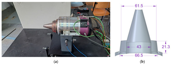
Figure 1.
(a) The Jet Cat P80 micro turbojet engine. (b) 3D CAD model of the nozzle cone.
In the current experimental campaign, the turbojet engine steadily operated at 3 different regimes in terms of shaft rotational speed for the baseline, the ejector configuration, and the Nextel 3M configuration. The first regime corresponds to the engine being idle (i.e., approx. 35,000 RPM), the second one was 68,500 RPM, and the third one was 112,600 RPM. The instrumentation system of the micro turbojet engine allows for the acquisition of several key operating parameters, such as thrust, fuel mass flow rate, air mass flow rate, combustion chamber pressure, combustion chamber temperature, temperature after the compressor, and engine rotational speed. In the present study, focus was placed on monitoring the temperature and pressure inside the combustion chamber as these are the most relevant for evaluating combustion and engine performance under the tested conditions. The ambient temperature during the experimental campaign was 23 °C. The exit velocity and Mach number were not directly measured as the current engine setup does not allow for such instrumentation. These parameters could be derived in future studies through CFD simulations or with an upgraded measurement campaign, where suitable probes and diagnostics would be installed to capture these flow characteristics.
For completeness, Table 1 shows the measured combustion chamber pressure and temperature for the operating regimes investigated in this study.

Table 1.
Average quantities at different regimes at the exit nozzle section.
T is the temperature in front of the turbine, and P is the pressure in the combustion chamber. It can be observed that the ejector influences the parameters during the operation of the micro turbojet engine, as detailed in reference [8].
2.1. Ejector Nozzle Configuration
The ejector is a device that creates a secondary airflow due to the phenomenon of ejection. Ejection refers to the process by which a passive fluid is entrained by an active fluid. This is possible because the primary fluid creates a low-pressure area, turning that zone into a suction zone, drawing in surrounding air with higher pressure, and thus generating the secondary jet. In jet engines, the ejector is typically mounted as an extension of the reaction nozzle, where it helps entrain air from the atmosphere to form a secondary flow, which mixes with the primary exhaust flow, leading to a single, quieter exhaust stream.
The ejector has been utilized in references [8,18], which provide a detailed description of its design and its impact on the engine’s performance, including the acoustic aspects. Figure 2 shows an image of the engine with the ejector configuration.
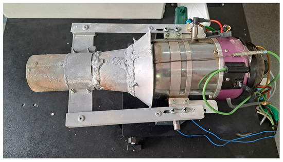
Figure 2.
The ejector nozzle configuration mounted on the micro turbojet.
Five microphones are arranged in a circular (polar) configuration (microphone M1 is at , microphone M2 is at , etc.), forming a quarter circle around the engine to capture sound propagation from all directions. This setup ensures spatially uniform sound measurements, with the microphones positioned equidistantly around the engine at equal angular intervals, at a distance of 1 m to the exhaust micro turbo engine, as illustrated in Figure 3. To report the distance of the microphone array in a dimensionless form, we needed to normalize the radial distance from the nozzle exit using a characteristic length scale of the jet. In this context, we consider the hydraulic diameter (equivalent diameter), given by Dh = 4S/P, where S is the cross-section area of the exit of the nozzle and P is the wetted perimeter of the flow. Explicitly, , where is the exterior and is the interior diameter (Figure 1b). Since the microphones were placed 1 m (1000 mm) away from the nozzle exit, the normalized distance is given by This normalization clarifies that the polar directivity measurements were conducted in the acoustic far field of the jet plume. The DEWEsoft Sirius multichannel system (24-bit ADC resolution, >160 dB dynamic range, and a sampling rate of up to 200 kS/s per channel, with ultra-low noise and distortion) integrates high-speed analog-to-digital conversion at 50 kS/s, real-time signal processing, and advanced spectral analysis techniques. This allows for accurate acoustic characterization under various biodiesel blend conditions and ejector configurations. DEWEsoft 2025.1 software was used to post-process the acoustic signals. For acoustic measurements, a DEWEsoft Sirius multichannel system with 24-bit ADC resolution, a high dynamic range exceeding 160 dB, and a sampling rate of up to 200 ks/s per channel was used. It integrates high-speed analog-to-digital conversion at a 50 ks/s sampling rate, real-time signal processing, and advanced spectral analysis techniques.
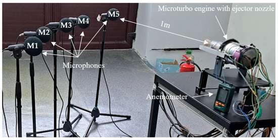
Figure 3.
Acoustic experimental test bench.
DEWEsoft software is designed to measure, analyze, and visualize sound pressure levels in compliance with international standards (IEC 61672 Class 1, IEC 60651/60804 [23], and ANSI S1.4 [24]). For this study, five G.R.A.S. 46AE free-field microphones, which meet the IEC 61094 WS2F [25] and IEC 61672 Class 1 standards [23], were used, ensuring high accuracy and reliability of acoustic measurements.
The tests were conducted at three operating regimes of the micro turbojet engine, defined by different rotational speeds: Regime 1—idle; Regime 2—intermediate; and Regime 3—maximum thrust. The instrumentation of the micro turbojet allows for precise control of the rotational speed and other parameters, as described in reference [8]. In the present study, the main focus was on the acoustic behavior generated by the exhaust jet.
2.2. NEXTEL 3M Configuration
The experimental configuration is centered around a micro turbojet engine mounted on a rigid, vibration-isolated bench to enable controlled acoustic and flow measurements. The focal innovation in this setup is the application of a 3M™ Nextel™ 312 ceramic fabric lining on the nozzle cone, clearly visible in Figure 4a,b.
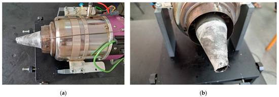
Figure 4.
(a) The 3M™ Nextel™ 312 ceramic fabric mounted on the micro turbojet. (b) Front view of the Nextel-lined nozzle cone.
This high-temperature textile is specifically chosen for its exceptional thermal resistance (up to 1200 °C) and mechanical durability under jet exhaust conditions. Nextel™ 312 is a flexible fibrous ceramic composed of continuous polycrystalline alumina-boria-silica oxide fibers, offering high thermal stability and exceptional resistance to oxidation and mechanical degradation under dynamic thermal loads. Its microstructure—characterized by high porosity and low bulk density (~2.8 g/cm3)—creates an impedance mismatch with the surrounding air, which promotes scattering, viscous damping, and multiple internal reflections of incident acoustic waves. These features make it particularly effective at attenuating mid- to high-frequency noise components, which are critical in jet propulsion applications [25,26,27,28,29]. To support reproducibility and contextual clarity, the relevant physical properties of the Nextel™ 312 fabric—such as thermal resistance, acoustic impedance, and material composition—are summarized in tabular form in Table 2 [28].
Table 2.
Typical properties of 3M™ Nextel™ 312 type AF-10 ceramic fiber.
Nextel 312 is not biodegradable but offers high durability, modularity, and long-term thermal–acoustic benefits. Most importantly, our study is—to the best of our knowledge—the first to propose and evaluate Nextel 312 as a replaceable acoustic liner applied to the central cone of a micro turbojet nozzle. This novel application introduces a structurally non-intrusive, reusable, and thermally resilient passive noise control strategy suitable for compact or embedded propulsion systems such as UAVs.
To securely adhere the Nextel fabric to the metal cone surface, Bison Fireplace Sealant, a refractory mastic rated for 1250 °C, was used. This adhesive ensures that the fabric remains intact and functional during full engine operation without degradation. The central cone was fully wrapped, targeting the shear layer region at the exhaust core—an area critical for the generation of small-scale turbulence and associated broadband noise.
The implementation of this ceramic liner is a first-of-its-kind attempt to suppress jet noise from within the nozzle through passive surface treatment without altering nozzle geometry or flow structure. The simplicity, weight efficiency, and thermal resilience of this configuration suggest a promising path forward for integrated, low-impact acoustic treatments in compact propulsion systems.
Figure 5 presents the thermal protection materials used in this study. Figure 5a shows the Bison high-temperature sealant, rated up to 1250 °C, which was used to bond the ceramic textile to the nozzle surface. Figure 5b captures a flame resistance test on the 3M™ Nextel™ 312 ceramic fabric, demonstrating its thermal integrity under direct heat exposure. Figure 5c displays several samples of Nextel™ 312 fabrics, highlighting the versatility of this material in aerospace applications requiring high strength and thermal resistance. These components form the basis of the innovative acoustic lining applied to the micro turbojet nozzle.
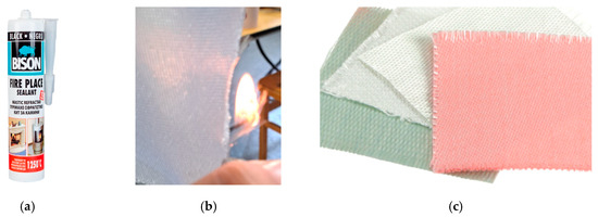
Figure 5.
(a) Commercially available Bison high-temperature sealant (rated up to 1250 °C). (b) Fire test. (c) Samples of different types of 3M™ Nextel™ 312 ceramic fabrics.
The pre-test pictures of the uncoated metallic cone nozzle and the ceramic fabric, mounted and sealed before the test are presented in Figure 6a,b, Thepost-test inspection revealed that the fabric (Figure 6c,d) was significantly degraded due to thermal and mechanical stresses—exhibiting signs of embrittlement and partial fraying. While no catastrophic delamination was observed, the liner was no longer reusable for subsequent tests. This outcome highlights that although the material withstands extreme conditions during operation, it functions as a consumable component intended for single use or periodic replacement in high-temperature jet environments. The 3M™ Nextel™ 312 ceramic fabric used in this study has a very low areal density of approximately 290 g/m2. In our configuration, the fabric was only applied to the central cone surface, covering an area of roughly 0.01 m2. This corresponds to an added mass of approximately 2.9 g—negligible in comparison to the overall mass of the turbojet engine (~3.2 kg). Therefore, the impact on the thrust-to-weight ratio is minimal (less than 0.1%) and does not compromise propulsion performance.
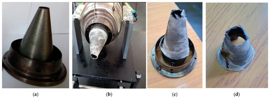
Figure 6.
(a) Uncoated metallic cone nozzle. (b) Cone nozzle with 3M™ Nextel™ 312 ceramic fabric, mounted and sealed before the test. (c,d) Post-test configuration of 3M™ Nextel™ 312 ceramic fabric after exposure to hot exhaust flow.
The acoustic tests were conducted in single-cycle regimes for each configuration, and no significant degradation in damping performance was observed during these short-term operations. However, the 3M™ Nextel™ 312 fabric showed signs of material fatigue and localized tearing post-test, indicating that it would likely require replacement for extended or repeated use. Surface temperature was not directly measured during operation, but the material’s integrity was visually assessed after exposure to exhaust flows exceeding 700–800 K, confirming its thermal resilience within expected operating limits. Future studies will include temperature diagnostics and multi-cycle durability assessment.
In the case of the ejector, according to the findings in reference [17], the performance of the micro turbojet was improved due to the contribution of the ejector. In contrast, the use of 3M Nextel does not alter the performance of the micro turbojet engine.
3. Results and Discussions
Noise reduction in micro turbojet engines is particularly challenging due to their small dimensions, which limit the use of traditional strategies like increasing mass flow or enlarging the nozzle to reduce exhaust velocity. Consequently, attention has shifted toward passive noise control methods involving nozzle geometry modifications and surface treatments. Two configurations were investigated: an ejector nozzle configuration mounted on the micro turbojet (Figure 2) and a novel setup using 3M™ Nextel™ 312 ceramic fabric. This innovative approach involves covering the central cone of the nozzle with high-temperature-resistant textile, marking the first known attempt to use such material as a passive noise mitigation strategy in a jet engine context.
The Nextel 3M lining was bonded using a high-performance refractory sealant, enabling it to withstand extreme thermal loads while remaining lightweight and flexible. This is particularly significant given that the central cone of a micro turbojet is subject to direct exposure from high-velocity, high-temperature exhaust gases. Until now, such regions have been considered too hostile for textile treatments due to the risk of thermal degradation. The Nextel textile, known for its high-temperature resistance, was applied using a refractory Bison sealant, aiming to suppress shear layer turbulence at its origin. Its refractory properties ensure structural integrity during high-temperature engine operation. The high-temperature Bison sealant used in this study is a commercially available, low-cost solution that proved highly practical. It was applied in a thin layer, approximately 0.5–1 mm thick, and cured rapidly at room temperature without requiring additional thermal treatment. The ceramic fabric remained firmly bonded to the cone throughout the entire test, showing no signs of delamination. At the end of the experiment, removal was easily performed manually, confirming the temporary and modular nature of the attachment.
In this experimental campaign, the micro turbojet engine was tested under three distinct steady-state rotational speeds, corresponding to different operating regimes. These included an idle state at 35,000 RPM, a medium power setting at 68,500 RPM, and a high-thrust regime at 112,850 RPM. However, the present paper focuses exclusively on the highest regime for acoustic analysis and comparison.
To assess the acoustic performance of each configuration, a semi-circular array of five microphones was deployed around the nozzle, covering angles ranging from 0° to 72° in 18° increments, such that the axis that contains the 90° angle is in line with the axis of the turbojet. This setup enabled directional sound pressure level (SPL) measurements and the computation of the directivity index (DI) across multiple regimes. Experimental tests were carried out using a Jet CAT P80 micro turbojet engine, available at the Aerospace Engineering Laboratory of the Polytechnic University of Bucharest. This engine has been extensively used in previous acoustic and aerodynamic studies [17,18].
3.1. Time and Frequency Acoustic Metric Analysis
In the field of acoustics data analysis, a representative time-averaged measure of noise exposure [30,31,32] is the equivalent X-weighted sound pressure level :
where is the X-weighted instantaneous sound pressure signal (n.b., the difference between instantaneous pressure and static pressure) in a certain period of discussion . In acoustic analysis, the three most used frequency X-weightings are A-weighting, C-weighting, and Z-weighting (n.b., also referred to as “zero” or unweighted). When the integration period covers the whole period of interest (e.g., the trimmed period for which the process is ergodic), , then we talk about the overall sound pressure level, denoted by (i.e., X = A, C, Z)
SPL(Z) is commonly referred to as OASPL (Z-weighted):
where represents the mean square of the pressure at frequency bin , is the number of frequency bins, and represents the mean square of the pressure over all frequencies. Regarding the period , we chose the entire period because the signal is selected such that it is ergodic, and the short-term variations in sound levels are insignificant [18].
A comprehensive acoustic comparison with respect to the OASPL, SPL(A), and SPL(C) was conducted across three operating regimes—R1 (low thrust), R2 (intermediate thrust), and R3 (high thrust)—for a micro turbojet engine using three different nozzle configurations: the standard Baseline, an Ejector nozzle, and a novel configuration featuring a thermal–acoustic lining based on 3M™ Nextel™ 312 ceramic fabric. Table 3 shows the values of the acoustic metrics, and Table 4 shows the corresponding standard deviations given for each measurement (OASPL, SPL(A), and SPL(C)) across the three configurations (Baseline, Ejector, and Nextel3M) for each region (R1, R2, and R3).
Table 3.
Global acoustic time metrics for baseline, ejector, and Nextel3M configurations across 3 regimes.
Table 4.
Standard deviations for acoustic time metrics across 3 regimes.
The acoustic performance suggests that this technique opens a new opportunity for passive noise control, which targets the root of shear layer turbulence generation directly at its origin.
As engine thrust increased from R1 to R3, the SPLs increased accordingly due to the intensified turbulent mixing and exhaust momentum. In the R1 regime, the acoustic differences between configurations were subtle, with all setups producing OASPLs in the mid-90 dB range. Even in this low-thrust state, however, the Nextel 3M treatment showed measurable reductions at certain microphone positions, suggesting that early shear layer interactions were being partially suppressed. The ejector’s performance was less distinctive in R1, reflecting its limited influence at lower jet energies.
In R2, the OASPL values increased by over 10 dB compared to R1, and the ejector began to show clear improvements in SPL(A) and SPL(C), confirming its role in enhancing jet mixing and reducing large-scale flow structures. Meanwhile, the Nextel 3M configuration demonstrated consistent performance across all metrics, in some cases even surpassing the ejector in OASPL reduction. This underlines the material’s capability to influence jet dynamics without introducing flow obstruction or complex hardware.
In the high-thrust regime R3, acoustic emissions reached their peak, and they are presented in Figure 7. The ejector achieved the greatest overall reduction in SPL(A)—dropping perceived noise to approximately 116.82 dB(A)—thanks to its ability to entrain ambient air and break down coherent vortices in the jet plume.
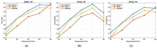
Figure 7.
(a) OASPL, (b) SPL(A), and (c) SPL(C) for all three configurations for the maximum regime.
The Nextel 3M ceramic lining, by contrast, delivered highly promising results in R3. It achieved OASPL and SPL(C) reductions nearly equivalent to those of the ejector while providing a noticeable improvement over the baseline in SPL(A). Most importantly, it did so with minimal structural impact and no changes to nozzle geometry. Regarding the standard deviation analysis, Table 4 reveals that the ejector configuration had the highest variability, with OASPL deviations reaching 1.69 dB in R1 and 2.78 dB in R3, indicating uneven attenuation. In contrast, Nextel3M showed more consistent performance, with lower or similar deviations such as 1.19 dB in the R1 OASPL and 2.40 dB in the R3 OASPL. While the ejector may reduce SPL(A) locally (e.g., 0.88 dB SD in R2), Nextel3M provided more stable broadband noise suppression across all regions.
Figure 8 illustrates the three time-averaged sound pressure levels, , and , for all three configurations, evaluated at the microphone position M5—where the directivity index reaches its maximum, considering a period of time . In regime R3 at microphone M5, , which emphasizes low-frequency content, shows visibly lower values for both the NEXTEL and ejector configurations compared to the baseline. This highlights their ability to attenuate low-frequency noise, which is critical for perceived rumble and structural vibrations. Additionally, , representing human-perceived loudness, is slightly lower for the ejector, suggesting superior overall attenuation in that regard. However, the NEXTEL configuration exhibits a smoother and more stable response, indicating consistent passive damping performance.
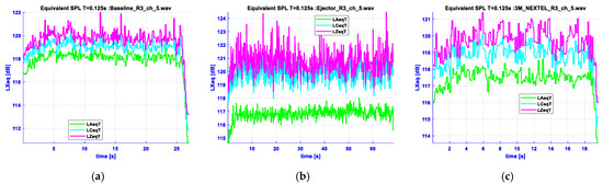
Figure 8.
Time-average sound pressure levels, ,, and , considering , for the maximum regime at the position with maximum directivity (M5) for all three configurations: (a) Baseline configuration, (b) Ejector configuration, (c) Nextel 3M configuration.
Figure 9a illustrates the power spectrum obtained via the periodogram method, highlighting which frequency components persist throughout the test duration (e.g., 11,250 Hz for baseline, 11,303 Hz for ejector, and 11,267 Hz for Nextel3M). The Power Spectral Density (PSD) reveals how signal energy is distributed across the frequency range, providing insights into the signal’s dominant frequency content. In Figure 9b, the PSD is calculated using four different PSD-based methods: using the spectrogram routine with (a) a Hamming window, (b) using short-time Fourier transform from the spectrogram routine with a Hamming window of the same sample size, (c) using the Welch periodogram, and (d) using an in-house algorithm in MATLAB R20222b. In Figure 9b a frequency appears around 11,250–11,300 Hz and its harmonic is at about 22,500–22,600 Hz (visible in the periodogram in Figure 9a). The explanation for this is that the signal selection was made at the maximum regime of the turbo microjet, operating at a rotational speed of 112,850 RPM (n = 1880.8 rev/s) for the ejector and for 112,610 RPM (n = 1876.8 rev/s) for NEXTEL 3M. The micromotor is equipped with a centrifugal compressor with B = 6 blades, and the theoretical frequency is around . The frequency predicted theoretically from the RPM of the engine and the number of compressor blades closely matches the measured spectral peak, confirming its origin in the compressor’s operation. This alignment indicates that the observed frequency is a distinct acoustic signature of the centrifugal compressor under the given operating conditions. The peak observed around 3757 Hz in the lower frequency range corresponds to the second harmonic of the compressor’s fundamental frequency. Table 5 shows very small differences in the OASPL values obtained using the four methods for all three configurations. Although the values are extremely close, the spectrogram and short-time Fourier transform (STFT) methods tend to give slightly higher values, especially for configuration “E”, while the in-house method, the power spectrogram, and the OASPL calculated using the pressure fluctuations provide almost identical results.
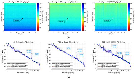
Figure 9.
Acoustics metrics for all three configurations: (a) power spectrum from periodogram, (b) power spectrum density for regime R3 at maximum directivity (M5) (n.b., this figure was generated in MATLAB as a vector graphic; readers are encouraged to zoom in for full clarity, as resolution is preserved at all scales).
Table 5.
OASPL comparison obtained in frequency domain for all configurations across 3 regimes.
3.2. Acoustic Footprint Analysis Polar Directivity
In the context of acoustic characterization of the noise, we compute an approximation of the directivity index (DI) for the jet engine using measurements from all five microphone arrays. DI, in simplified 2D case, is defined as
where is the directivity factor given by the expression
where is the sound intensity at angle , is the average of the sound intensity across the polar array, and is the angular span of the microphone arc, in radians.
The acoustic intensity signal is given by
where are, respectively, the sound velocity and the density in reference conditions. Let us reiterate that at a certain position, the fluctuation in pressure is used to compute the root mean square for the acoustic pressure:
The integral is calculated numerically with Simpson’s 1/3 method. The DI offers insights into the spatial distribution of acoustic energy around the nozzle and highlights how directional the sound field is in each configuration. It quantifies how much louder the sound is in a particular direction compared to the average over the entire angular range. A higher DI (greater than 0) indicates more focused noise emission, while a lower DI (less than 0) suggests a less intense radiation pattern. The directivity index analysis reveals how each nozzle configuration—baseline, ejector, and the novel 3M™ Nextel™ 312 ceramic lining—distributes acoustic energy directionally across low (R1), intermediate (R2), and high thrust (R3) regimes; the results are given in Figure 10, with the corresponding values specified in Table 6.
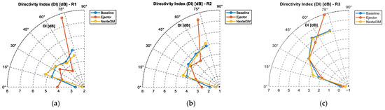
Figure 10.
The polar directivity patterns of the three regimes: (a) regime R1, (b) regime R2, (c) regime R3 The axis of the engine is in the direction of 90°.
Table 6.
Directivity index for baseline, ejector, and Nextel3M configurations for 3 regimes.
In regime R1, DI values are generally low for all configurations, with most values hovering near 0–5 dB. The ejector shows directional behavior, particularly at M5 (72°) with a peak DI of 7.67 dB, indicating that even at low thrust, it begins to channel acoustic energy directionally, which could be explained due to early shear layer interaction. Nextel3M and the baseline exhibit lower DI values (e.g., 4.59 dB and 5.02 dB at M5), suggesting more diffuse radiation and less directional concentration of acoustic energy. In regime R2, this pattern strengthens as follows: the ejector consistently shows the highest DI at M5 (7.43 dB), while Nextel3M remains more uniform across all angles, never exceeding 5.19 dB, even at the maximum directivity point. This behavior confirms that the ejector nozzle geometry enforces stable directional noise radiation, likely due to its flow-modifying chevrons.
In regime R3, at maximum thrust, Nextel3M achieves the most uniform DI profile, with values ranging only between −0.62 dB and 5.22 dB, showing minimal directionality even at a high noise output. The ejector, on the other hand, again peaks at M5 with 6.95 dB, maintaining its tendency to focus noise into a narrow angular region.
Overall, while the ejector achieves the highest directional suppression, it also focuses noise into specific angles, like 72°, in the direction of microphone M5.
In contrast, the Nextel3M treatment provides a more uniform and balanced acoustic field across regimes, making it a promising, low-complexity solution for reducing both sound level and acoustic footprint without introducing new directional hot spots.
3.3. Third-Octave Spectral Band Analysis
To deepen the understanding of how each nozzle configuration affects the spectral content of the emitted sound, we performed a third-octave band decomposition of the SPL using the Welch periodogram, as shown in Figure 11, for all microphone positions (M1–M5) in the maximum thrust regime (R3). While metrics such as the overall sound pressure level (OASPL) and directivity index (DI) offer valuable insights into the global amplitude and spatial distribution of noise, they lack the resolution needed to identify which frequency components are most affected by each treatment.
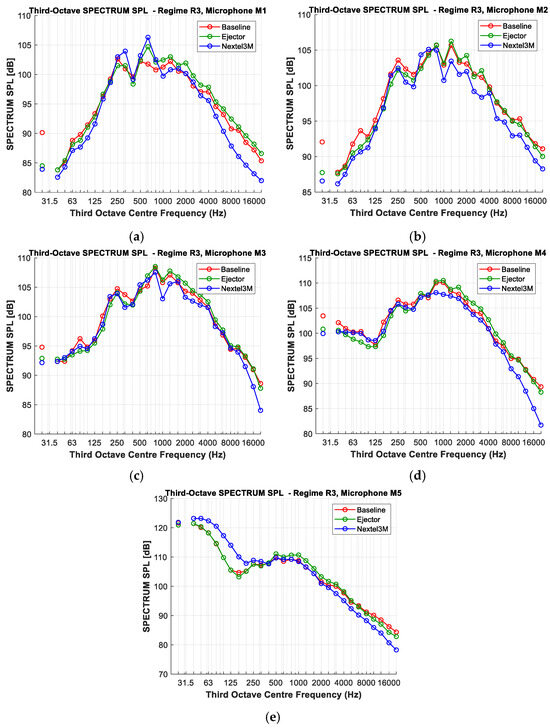
Figure 11.
Third-octave SPECTRUM SPL comparison at R3 at microphones (a) M1, (b) M2, (c) M3, (d) M4, (e) M5 (n.b., this figure was generated in MATLAB as a vector graphic; readers are encouraged to zoom in for full clarity as resolution is preserved at all scales).
These plots reveal that both treatments generally reduce overall noise levels, particularly at higher frequencies, although the degree of reduction varies with the measurement angle. Specifically, at off-axis locations (M1 and M2), the Nextel configuration demonstrates consistent and often more significant attenuation in the mid to high frequencies compared to the ejector. At intermediate angles (M3 and M4), both treatments offer high-frequency suppression, with Nextel typically providing a greater reduction. However, at the microphone positioned in the direction of maximum acoustic radiation (M5), while Nextel effectively attenuates higher frequencies, it also exhibits an increase in the low-frequency SPL, a trend less prominent with the ejector. While the absolute SPL spectra, given in Figure 11, provide an overview of the noise levels with each treatment, analyzing the relative third-octave SPL (configuration treatment minus baseline) shown in Figure 12 offers a more direct and insightful quantification of the specific attenuation or amplification introduced by the ejector and Nextel configurations at each individual frequency band.
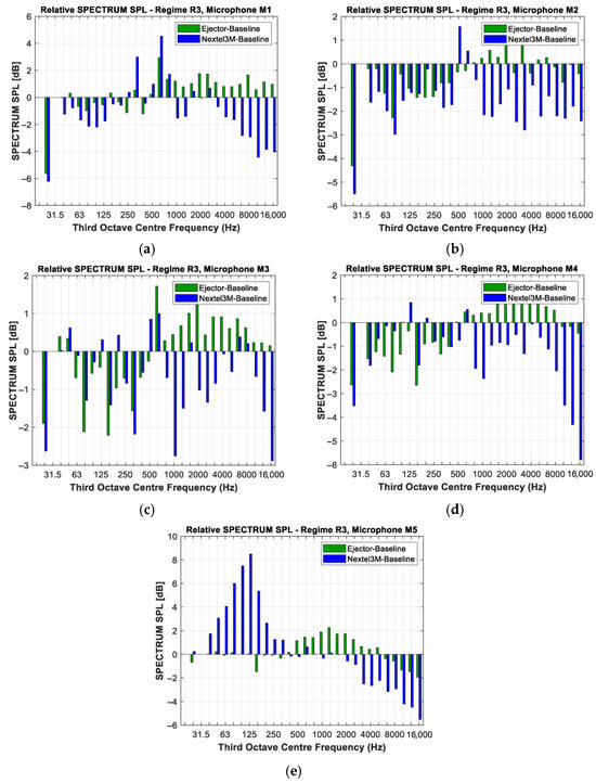
Figure 12.
Relative third-octave SPL comparison at R3 between the ejector configuration or Nextel 3M minus the baseline at microphones (a) M1, (b) M2, (c) M3, (d) M4, (e) M5.
This comparative evaluation of the relative third-octave SPL between ejector–baseline and Nextel3M–baseline, across microphones M1 to M5, reveals that the 3M™ Nextel™ configuration consistently provides more notable attenuation than the ejector in several key frequency regions. Except for the third-octave bands between 250 Hz and 800 Hz (especially around 630 Hz), Nextel consistently provides broadband suppression across a wide frequency range at off-axis microphones (M1 and M2), with reductions of up to −5 dB in some bands (negative bins indicate attenuation relative to the baseline).
At microphones M3 and M4, the Nextel lining consistently provides a greater reduction in sound pressure levels (more negative blue bins) compared to the ejector across most of this range. In the lower mid-frequency range (under 630 Hz), the Nextel configuration exhibits an amplification of the sound (positive blue bins) at both M5, while the ejector’s impact in this region is less pronounced. At the same time, in the frequency range of 630 Hz to 8000 Hz, at M5, the ejector configuration results in an increase in the sound pressure level (positive green bins), while Nextel provides significant attenuation (negative blue bins). In summary, except for a few low-frequency third-octave bands (particularly around 250–630 Hz), the overall spectral data strongly indicates that the Nextel lining acts as an effective attenuator of jet noise, making it a promising passive noise reduction strategy for the micro turbojet nozzle’s central cone in many, but not all, spectral regions and measurement directions. The observed high-frequency noise attenuation by the Nextel lining suggests that its noise reduction benefits are likely more pronounced in the near field. This characteristic could be particularly advantageous for ground engine operations, where localized noise reduction is a key concern for personnel and surrounding infrastructure.
3.4. Proper Orthogonal Decomposition (POD) Analysis of Acoustic Field
Proper Orthogonal Decomposition (POD) is a powerful classical technique used to extract dominant patterns (or modes) from multi-sensor data [33,34,35,36]. In the context of microphone arrays, POD helps identify how the energy of the acoustic field is distributed across spatial–temporal structures. Each mode represents a coherent structure in the sound field with its associated energy contribution. If the measured microphone data is represented as a matrix, , where is the number of time samples and is the number of microphones, we apply Singular Value Decomposition (SVD) to decompose the signal matrix:
Let us reiterate that contains the temporal modes (left singular eigenvectors), is the diagonal matrix of singular values, and contains the spatial modes (right singular vectors). The energy captured by POD mode is proportional to the square of its singular value , and the percentage of total energy in each mode is
For regime R3, we compared the same three configurations in Figure 13, and the corresponding values are given in Table 7. As shown in the comparative results, the ejector configuration displays the lowest energy in the first mode (30.8%), suggesting a stronger dispersion of energy into higher-order modes, which reflects a more diffused and turbulent sound field. Mode 1 captures the most dominant and structured component of the sound field—typically associated with large-scale, organized noise sources. Higher-order modes (e.g., Modes 2, 3, etc.) reflect increasingly finer, less coherent, and more turbulent features of the sound field.
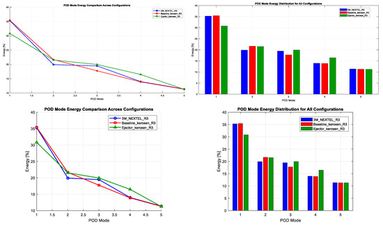
Figure 13.
POD modes for the three configurations in two representations.
Table 7.
POD energy distribution for baseline, ejector, and Nextel3M configurations for regime R3.
Analyzing the distribution of energy among these modes allows us to infer how each configuration (baseline, ejector, and Nextel3M) affects the coherence and structure of the emitted noise. A lower Mode 1 energy suggests more dispersion and less dominance of large-scale structures, while a higher and more balanced spread across modes indicates broader spatial diffusion. This analysis is particularly helpful in distinguishing between noise control strategies that suppress coherent sources versus those that redistribute acoustic energy more diffusely.
This behavior confirms its well-known role as a passive acoustic attenuator, effectively reducing coherent sound content. In contrast, the baseline and NEXTEL-treated configurations retain higher energy in the first mode (~35%), indicating more structured and coherent acoustic fields. However, an important distinction emerges: the NEXTEL setup spreads the remaining energy more evenly between the second and third modes (19.9% and 19.5%, respectively) in contrast to the Baseline, which shows a gap between these modes.
This more balanced energy distribution in NEXTEL may indicate more isotropic spatial behavior or a partial reduction in directional sound features even though it does not reduce the dominant mode energy as much as the ejector. Taken together, these results suggest complementary strengths between the two approaches: the ejector excels in suppressing dominant coherent structures, while the NEXTEL coating helps redistribute and potentially diffuse remaining energy components. This opens a promising avenue for future experimental work to investigate the combined effect of NEXTEL-treated surfaces and ejector geometries, potentially yielding enhanced overall acoustic attenuation and spatial redistribution of jet noise.
3.5. Graph Signal Processing (GSP) for Microphone Array Analysis
In aeroacoustic studies, especially for micro turbojet noise evaluation, traditional metrics like the SPL and directivity often assume a symmetric sound field centered along a main radiation axis. However, jet noise is mostly turbulent, multi-directional, and affected by scattering, making these assumptions unreliable.
Graph Signal Processing (GSP) provides a distinct framework to analyze the spatial coherence and structure of microphone array data without requiring such symmetry to be an extension of classical signal processing to an irregular structure. GSP models the array of the microphones as a graph (G), the vertex (V) by microphones, and the edges (E) by how close or “connected” they are (we assume a regular circular structure). With the help of this theory [36,37] we can compute two important features of the acoustic field: graph smoothness (GS) and spectral spread (SS). First, we compute the graph Laplacian with the expression
where is the adjacency matrix which is widely adopted, namely the Pearson correlation coefficient of , with zeros on the main diagonal (n.b., remove self-connections), and is a diagonal matrix, constructed such that . Let us reiterate that is the number of time samples, and is the number of microphones. Reconsidering the signal matrix written in the form , where we denoted the spatial signal across all microphones at one time with , column vectors, the total graph smoothness (GS) over the measured time is given by the following quadratic form [37,38]:
where signifies the spatial signal across all microphones at one time. To compute the spectral spread (SS) in GSP, we perform the eigenvalue decomposition of the graph Laplacian by , where the matrix I is the diagonal matrix containing the eigenvalues of and the matrix is the orthonormal matrix of eigenvectors. Then, we compute the Graph Fourier Transform [36] with
The vector’s components of are the coefficients at time for each Laplacian eigenvalue (n.b., graph frequencies). The vector energy at each time is , where measures how much energy of the signal at time is present at graph frequency . The mean energy in graph frequency across all time steps is
The eigenvector decomposition for the graph Laplacian was carried out. Spatial coherence was quantified using Graph Signal Processing metrics such as spectral spread (SS), computed according to established methodologies [38,39] as follows:
where is the total graph energy.
Table 8 provides the Laplacian eigenvalues representing the spatial frequencies on the graph and quantifying the variability of signal components across the array.
Table 8.
Spectral spread and graph smoothness for all configurations for regime R3.
The Graph Signal Processing analysis reveals distinctly different spatial acoustic signatures across the three engine configurations, with each noise control mechanism producing fundamentally different spatial organization patterns that complement traditional amplitude-based noise reduction. A smaller set of dominant eigenvalues (n.b., near 0) suggests that the signal is composed mostly of low graph frequency components, meaning it varies slowly over the graph, i.e., there are similar values at adjacent microphones given that most of the signal content is spatially coherent. Large eigenvalues (toward ) correspond to high graph frequencies, i.e., signals that change abruptly between nodes, reflecting complex, noisy, or turbulent fields. The ejector configuration demonstrates the highest spatial organization with the lowest graph smoothness (GS = 45,140), the lowest spectral spread (SS = 0.2745), and the highest total energy (573,342). This confirms that ejectors break down large-scale, low-frequency vortical structures into organized, high-frequency turbulence, which attenuates more effectively during far-field propagation while potentially maintaining coherent directional characteristics. Although it effectively organizes turbulent structures for far-field benefits, it does not reduce the source energy itself.
In contrast, the 3M_NEXTEL_R3 configuration achieves the lowest total energy and exhibits the highest spatial incoherence (GS = 103,293) and the widest spectral spread (SS = 0.5253), meaning the acoustic field is spatially scattered and uncorrelated across the array. While this suggests greater spatial disorder, it is in fact a desirable effect: the acoustic liner disrupts coherent noise patterns and spreads energy across a broader range of spatial modes. This confirms that NEXTEL acts as a dual-mode noise control mechanism, absorbing sound through material damping and scattering energy to suppress organized wavefronts. This combination enhances near-field safety by reducing localized pressure peaks and complements the liner’s energy absorption properties to lower overall sound pressure levels (SPLs).
4. Conclusions
This study investigated the acoustic behavior of three nozzle configurations—baseline, ejector, and a novel passive treatment using 3M™ Nextel™ 312 ceramic fabric—applied to the central cone of a micro turbojet. To the best of our knowledge, this is the first time such a ceramic fabric has been applied in such context for jet noise reduction. The method introduces a high-temperature, lightweight, and modular passive liner that could be designed as a consumable or replaceable acoustic treatment, suitable for compact or unmanned propulsion systems. To ensure a comprehensive comparison between these configurations, the analysis was structured into five main components: time and frequency-domain acoustic metrics, acoustic footprint and polar directivity, third-octave band spectral analysis, the Proper Orthogonal Decomposition (POD) of the acoustic field, and Graph Signal Processing (GSP) for microphone array spatial structure evaluation.
Time and frequency-domain analysis shows that both the ejector and Nextel3M configurations reduce acoustic emissions compared to the baseline, particularly in the high-thrust regime (R3). The ejector is the most effective in lowering perceived noise (SPL(A)), making it well-suited for applications where far-field or community noise is critical. Meanwhile, Nextel3M offers comparable reductions in overall and low-frequency levels (OASPL and SPL(C)), with the added advantage of minimal structural impact, making it ideal for compact systems and near-field noise control. This highlights their complementary roles in targeted acoustic mitigation strategies.
The directivity analysis shows that the ejector consistently produces the most directional acoustic field, with peak DI values at microphone 5 (72°), especially under high thrust (R3). This focused emission can enhance far-field noise control but may increase localized exposure. In contrast, the Nextel3M liner maintains a uniform directivity profile across all regimes, effectively reducing the acoustic footprint without concentrating energy in specific directions. This makes it particularly suitable for near-field noise mitigation in environments where broad spatial damping is preferred.
Third-octave spectral analysis reveals that Nextel3M provides broader and more consistent high-frequency attenuation than the ejector, especially at off-axis positions (M1–M4). This makes it particularly effective for near-field noise control, where high-frequency components dominate perceived loudness and discomfort. While the ejector shows less amplification at low frequencies and maintains better performance at M5, it tends to increase the SPL in certain mid-frequency bands. In contrast, Nextel reduces broadband noise more effectively, confirming its role as a passive, frequency-selective damping treatment. These differences highlight their complementary noise reduction profiles depending on direction and frequency.
POD analysis confirms that the ejector configuration most effectively breaks down dominant acoustic structures, as shown by the lowest Mode 1 energy (30.8%), dispersing sound into higher-order, less coherent modes. In contrast, Nextel3M retains strong energy in the first mode (35.3%), but with a more balanced energy spread across Modes 2 and 3, suggesting that it preserves some coherence while promoting spatial diffusion. This distinction highlights complementary damping strategies: the ejector disrupts dominant flow-induced noise structures, while Nextel smooths and redistributes residual energy, pointing to the potential synergy of hybrid designs.
GSP analysis reveals that the ejector produces the most spatially organized acoustic field, with the lowest graph smoothness (GS) and spectral spread (SS), indicating structured turbulence that favors far-field attenuation. However, it maintains the highest total energy, highlighting limited source damping. In contrast, Nextel3M maximizes spatial scattering (highest GS and SS) and achieves the lowest acoustic energy, showing that it effectively absorbs and diffuses noise. This makes it ideal for near-field protection, confirming that each treatment targets different spatial-noise mechanisms, offering complementary strengths in jet noise control.
Together, these findings demonstrate that the ejector and Nextel3M configurations offer complementary advantages across multiple acoustic analysis dimensions. The ejector excels in directional control and far-field noise mitigation by redistributing low-frequency energy and suppressing coherent structures. However, this comes at the cost of added complexity, weight, and directional noise concentration. In contrast, the Nextel3M lining offers broadband damping and spatial diffusion benefits that enhance near-field acoustic safety without altering nozzle geometry. It passively attenuates early turbulence, reduces total acoustic energy, and ensures smoother spectral and spatial distribution, making it ideal for compact propulsion systems such as UAVs where space, thermal resilience, and simplicity are critical.
While the ejector remains the most effective for far-field suppression, Nextel3M emerges as a novel modular solution that targets near-field exposure risks. The potential for combining both treatments into hybrid designs could lead to next-generation jet noise suppression strategies that are not only acoustic efficient but also structurally and thermally integrable. Its flexibility, high thermal resistance, and low added mass make it a promising candidate for modular surface-mounted treatments in more complex configurations. Importantly, due to its simplicity and passive nature, the concept may be particularly suitable for ground-based (terrestrial) engine installations, such as engine test stands, auxiliary power units, or stationary jet exhaust systems—scenarios where weight and in-flight integration are less critical. In these contexts, the liner could offer a robust and low-maintenance solution for reducing broadband noise and protecting surrounding infrastructure or personnel from acoustic exposure.
Author Contributions
Conceptualization, A.B., G.C. and A.-G.T.; methodology, D.-E.C.; software, A.B. and L.C.; validation, G.C. and C.L.; writing—original draft preparation, A.B., G.C. and C.L.; writing—review and editing, A.B., G.C., C.L. and A.-G.T. All authors have read and agreed to the published version of the manuscript.
Funding
This research was funded by the National Program for Research of the National Association of Technical Universities—GNAC ARUT 2023, grant no. 81/11/10.2023.
Institutional Review Board Statement
Not applicable.
Informed Consent Statement
Not applicable.
Data Availability Statement
The original contributions presented in this study are included in the article; further inquiries can be directed to the corresponding authors.
Acknowledgments
The authors gratefully acknowledge Insul. Tecno Group, Binasco (MI), Italy, for providing the high-performance ceramic fabrics used in this study, including full coverage of international transport costs. Special thanks to Giorgio Cavallaro for coordinating the material supply and to Mauro Laterza and Stefan Friedrich from 3M Advanced Materials Division for their expert guidance and technical support in selecting appropriate 3M™ Nextel™ fabric solutions for high-temperature noise mitigation applications.
Conflicts of Interest
The authors declare no conflicts of interest.
References
- Flight Operations Support and Line Assistance. Getting to Grips with Aircraft Noise; Airbus: Leiden, France, 2003; Available online: https://www.smartcockpit.com/download/getting-to-grips-to-aircraft-noise/ (accessed on 10 March 2023).
- Cumpsty, N.A. A Critical Review of Turbomachinery Noise. J. Fluid. Eng. 1977, 99, 278–293.3. [Google Scholar]
- Torija, A.; Self, R. Aircraft classification for efficient modelling of environmental noise impact of aviation. J. Air Transp. Manag. 2018, 67, 157–168. [Google Scholar] [CrossRef]
- Smith, M.J.T. Aircraft Noise; Cambridge University Press: Cambridge, UK, 1989. [Google Scholar]
- Sadeghian, M.; Bandpy, M.G. Technologies for aircraft noise reduction: A review. J. Aeronaut. Aerosp. Eng. 2020, 9, 219. [Google Scholar]
- Bianchi, S.; Corsini, A.; Sheard, A.G. A Critical Review of Passive Noise Control Techniques in Industrial Fans. J. Eng. Gas Turbines Power. 2014, 136, 044001. [Google Scholar] [CrossRef]
- Sawyer, S.; Fleeter, S. Passive Control of Turbomachine Noise. In Proceedings of the International Compressor Engineering Conference, West Lafayette, IN, USA, 14–17 July 1998; p. 1336. [Google Scholar]
- Cican, G.; Frigioescu, T.-F.; Crunteanu, D.-E.; Cristea, L. Micro Turbojet Engine Nozzle Ejector Impact on the Acoustic Emission, Thrust Force and Fuel Consumption Analysis. Aerospace 2023, 10, 162. [Google Scholar] [CrossRef]
- Zhang, Z.; Wang, C.; Yang, S.; Cheng, F.; Geng, J.; Yang, Z.; Lyu, Y.; Yu, L. Research on performance of multi-nozzle ejector for aeroengine air system. Therm. Sci. Eng. Prog. 2023, 38, 101651. [Google Scholar]
- Aidoun, Z.; Ameur, K.; Falsafioon, M.; Badache, M. Current Advances in Ejector Modeling, Experimentation and Applications for Refrigeration and Heat Pumps. Part 2: Two-Phase Ejectors. Inventions 2019, 4, 16. [Google Scholar] [CrossRef]
- Besagni, G. Ejectors on the cutting edge: The past, the present and the perspective. Energy 2019, 170, 998–1003. [Google Scholar] [CrossRef]
- Presz, W.M., Jr.; Reynolds, G.; Hunter, C. Thrust augmentation with mixer/ejector systems. In Proceedings of the 40th AIAA Aerospace Sciences Meeting & Exhibit, Reno, NV, USA, 14–17 January 2002. [Google Scholar] [CrossRef][Green Version]
- Greatrex, F.B. Jet Noise; Preprint No. 559, S.M.F. Publ. Fund Preprint; Institute of Aeronautical Sciences Inc.: New York, NY, USA, 1955. [Google Scholar]
- Moore, C.J. The Role of Shear-Layer Instability Waves in Jet Exhaust Noise. J. Fluid Mech. 1977, 80 Pt 2, 321–367. [Google Scholar]
- Krasheninnikov, Y.; Mironov, A.K. Aerodynamic and acoustic characteristics of turbulent jet flows in mixer-ejector exhaust systems. In Proceedings of the 5th International Symposium on Transport Noise and Vibration, St. Petersburg, Russia, 6–8 June 2000; EEAA Publication: Copenhagen, Denmark, 2000. [Google Scholar]
- Bogoi, A.; Cican, G.; Gall, M.; Totu, G.; Crunțeanu, D.E.; Levențiu, C. Comparative Study of Noise Control in Micro Turbojet Engines with Chevron and Ejector Nozzles Through Statistical, Acoustic and Imaging Insight. Appl. Sci. 2025, 15, 394. [Google Scholar] [CrossRef]
- Cican, G.; Gall, M.; Bogoi, A.; Deaconu, M.; Crunțeanu, D.E. Experimental Investigation of a Micro Turbojet Engine Chevrons Nozzle by Means of the Experimental Investigation of a Micro Turbojet Engine Chevrons Nozzle by Means of the Schlieren Technique. Inventions 2023, 8, 145. [Google Scholar] [CrossRef]
- Cican, G.; Deaconu, M.; Crunţeanu, D.E. Impact of Using Chevrons Nozzle on the Acoustics and Performances of a Micro Turbojet Engine. Appl. Sci. 2021, 11, 5158. [Google Scholar] [CrossRef]
- Gliebe, P.R. Aeroacoustics in Turbomachines and Propellers-Future Research Needs. In Proceedings of the 6th International Symposium on Unsteady Aerodynamics, Aeroacoustics and Aeroelasticity in Turbomachines and Propellers, Paris, France, September 1991. [Google Scholar]
- Nark, D.M.; Jones, M.G.; Sutliff, D.L. Modeling of Broadband Liners Applied to the Advanced Noise Control Fan. In Proceedings of the 21st AIAA/CEAS Aeroacoustics Conference, Dallas, TX, USA, 22–26 June 2015; pp. 2015–2693. [Google Scholar]
- Hultgren, L.S. Core/Combustor Noise—Research Overview, Acoustics Technical Working GroupMeeting; NASA Langley Research Center: Hampton, VA, USA, 2017. [Google Scholar]
- Available online: https://www.newtex.com/assets/pdf/textiles/pds/3m_nextel_high_temperature_application_bulletin.pdf (accessed on 4 April 2025).
- IEC 61672-1; Electroacoustics—Sound Level Meters—Part 1: Specifications. International Electrotechnical Commission: Geneva, Switzerland, 2013. Available online: https://webstore.iec.ch/en/publication/5708 (accessed on 2 May 2025).
- ANSI/ASA S1.20-2014/Part 1; Procedures for the Comparison of Sound Level Meters with Specified Class Performance. American National Standards Institute/Acoustical Society of America: New York, NY, USA, 2014. Available online: https://webstore.ansi.org/standards/asa/ansiasas12014partiec616722013 (accessed on 2 May 2025).
- IEC 61094-4; Measurement Microphones—Part 4: Specifications for Working Standard Microphones. International Electrotechnical Commission: Geneva, Switzerland, 1995. Available online: https://webstore.iec.ch/en/publication/4488 (accessed on 2 May 2025).
- Available online: https://multimedia.3m.com/mws/media/1373324O/nextel-for-aerospace-applications.pdf (accessed on 29 June 2025).
- Available online: https://www.fire.tc.faa.gov/2016Conference/files/Materials_V_Flame_Propagation/SinghCeramicFabric/SinghCeramicFabricPres.pdf (accessed on 29 June 2025).
- Available online: https://multimedia.3m.com/mws/media/1327055O/3m-nextel-technical-reference-guide.pdf (accessed on 29 June 2025).
- Christiansen, E.L.; Davis, B.A. Heat-Cleaned Nextel in MMOD Shielding. Available online: https://ntrs.nasa.gov/api/citations/20190033497/downloads/20190033497.pdf (accessed on 29 June 2025).
- Beranek, L. Acoustics; McGraw Hill: New York, NY, USA, 1954. [Google Scholar]
- ISO 3744:1994; Acoustics—Determination of Sound Power Levels of Noise Sources Using Sound Pressure—Engineering Method in an Essentially Free Field over a Reflecting Plane. Institute of Noise Control Engineering: Wakefield, MA, USA, 1996.
- ISO 3740:2000; Acoustics—Determination of Sound Power Levels of Noise Sources—Guidelines for the Use of Basic Standards. ISO: Geneva, Switzerland, 2000.
- Lumley, J.L. The Structure of Inhomogeneous Turbulent Flows. In Proceedings of the International Colloquium, Moscow, Russian, 4–9 June 1965. [Google Scholar]
- Luo, Z.; Wang, R.; Zhu, J. Finite difference scheme based on proper orthogonal decomposition for the nonstationary NavierStokes equations. Sci. China Ser. A. Math. 2007, 50, 1186–1196. [Google Scholar]
- Berkooz, G.; Holmes, P.; Lumley, J.L. The Proper Orthogonal Decomposition in the Analysis of Turbulent Flows. Annu. Rev. Fluid Mech. 1993, 25, 539–575. [Google Scholar] [CrossRef]
- Sandryhaila, A.; Moura, J. Discrete Signal Processing on Graphs. IEEE Trans. Signal Process. 2013, 61, 1644–1656. [Google Scholar]
- Shuman, D.I.; Narang, S.K.; Frossard, P.; Ortega, A.; Vandergheynst, P. The emerging field of signal processing on graphs: Extending high-dimensional data analysis to networks and other irregular domains. IEEE Signal Process. Mag. 2013, 30, 83–98. [Google Scholar]
- Ortega, A.; Frossard, P.; Kovačević, J.; Moura, J.M.F.; Vandergheynst, P. Graph Signal Processing: Overview, Challenges, and Applications. Proc. IEEE 2018, 106, 808–828. [Google Scholar]
- Mateos, G.; Segarra, S.; Marques, A.G.; Ribeiro, A. Connecting the dots: Identifying network structure via graph signal processing. IEEE Signal Process. Mag. 2019, 36, 16–43. [Google Scholar]


Disclaimer/Publisher’s Note: The statements, opinions and data contained in all publications are solely those of the individual author(s) and contributor(s) and not of MDPI and/or the editor(s). MDPI and/or the editor(s) disclaim responsibility for any injury to people or property resulting from any ideas, methods, instructions or products referred to in the content. |
© 2025 by the authors. Licensee MDPI, Basel, Switzerland. This article is an open access article distributed under the terms and conditions of the Creative Commons Attribution (CC BY) license (https://creativecommons.org/licenses/by/4.0/).