
Experimental Evaluation of the Effects of SRP Reinforcement on the Flexural Behavior of CLT Panels


Abstract
1. Introduction
2. Experimental Tests
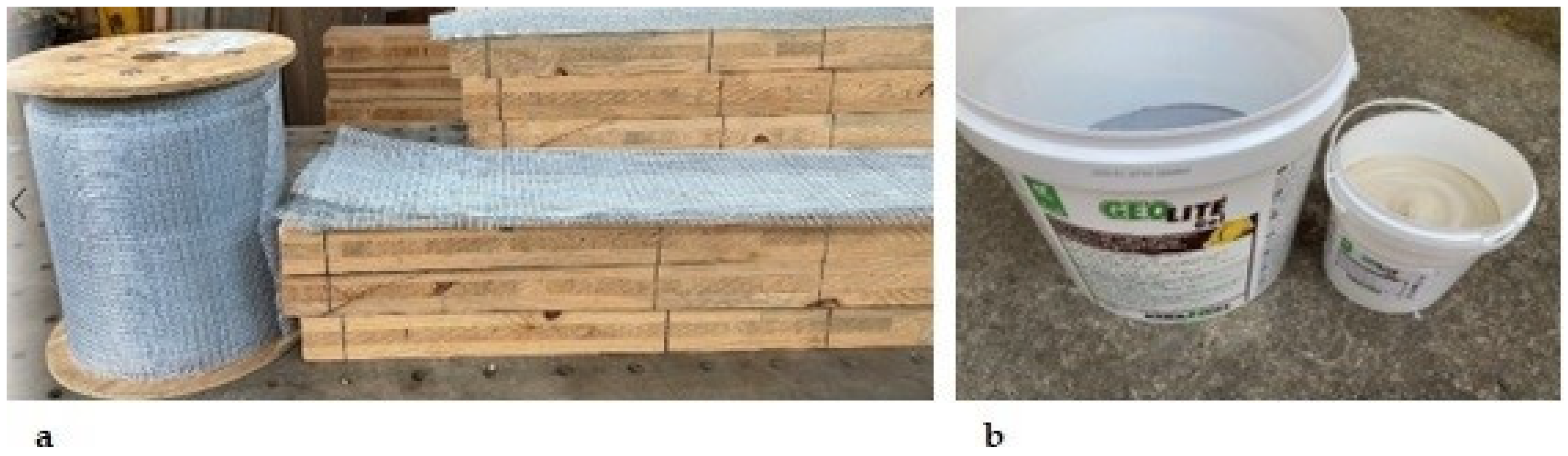
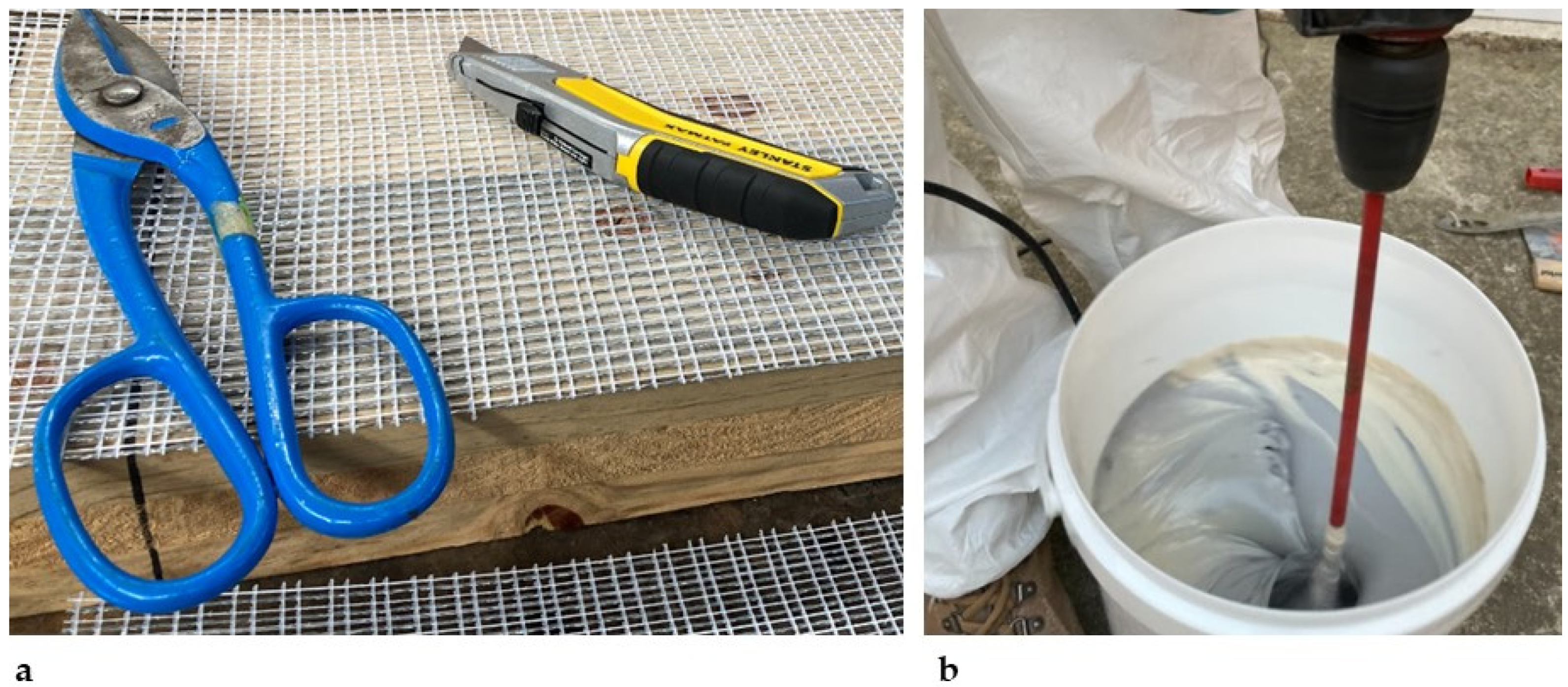
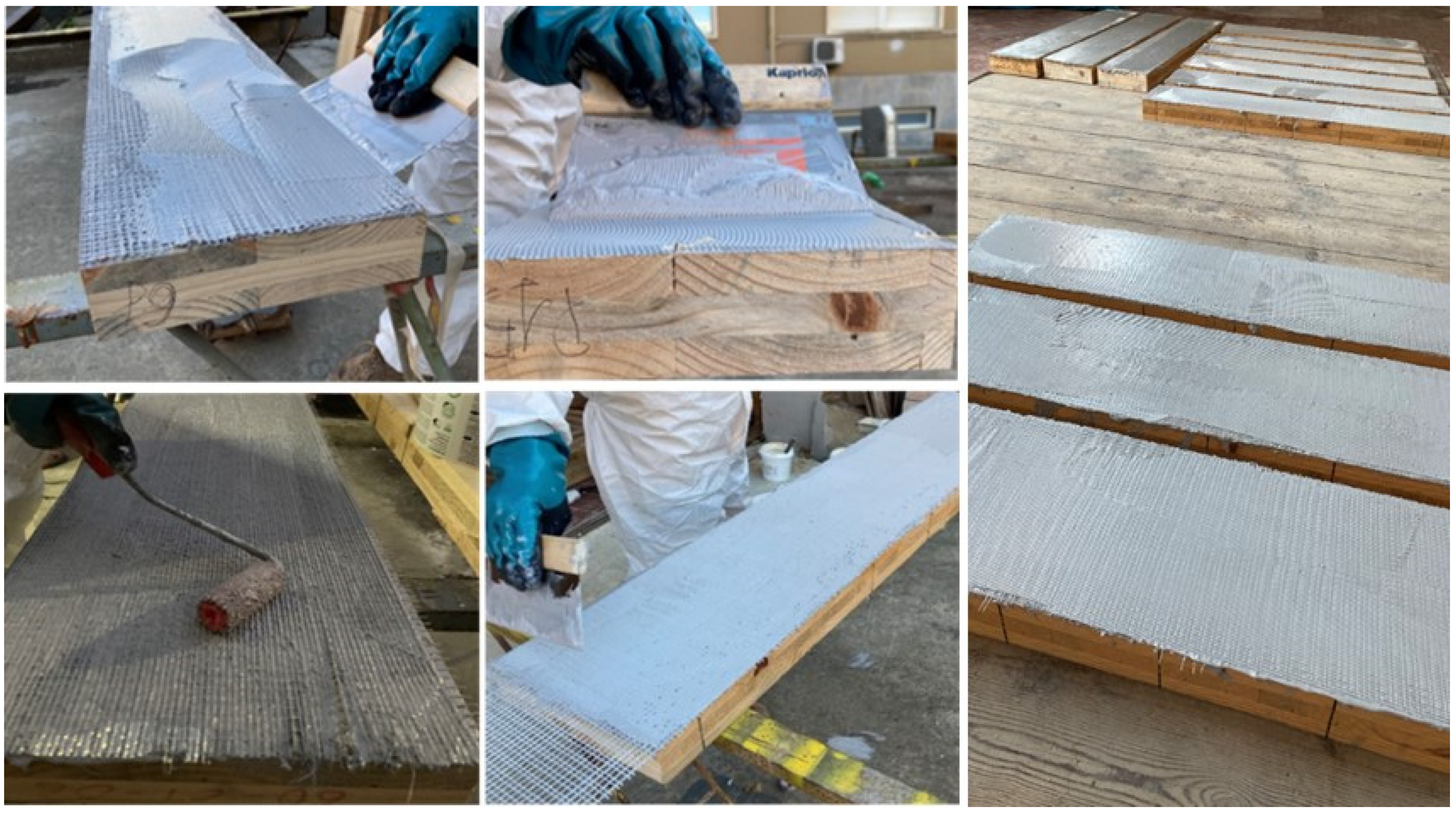
2.1. Materials
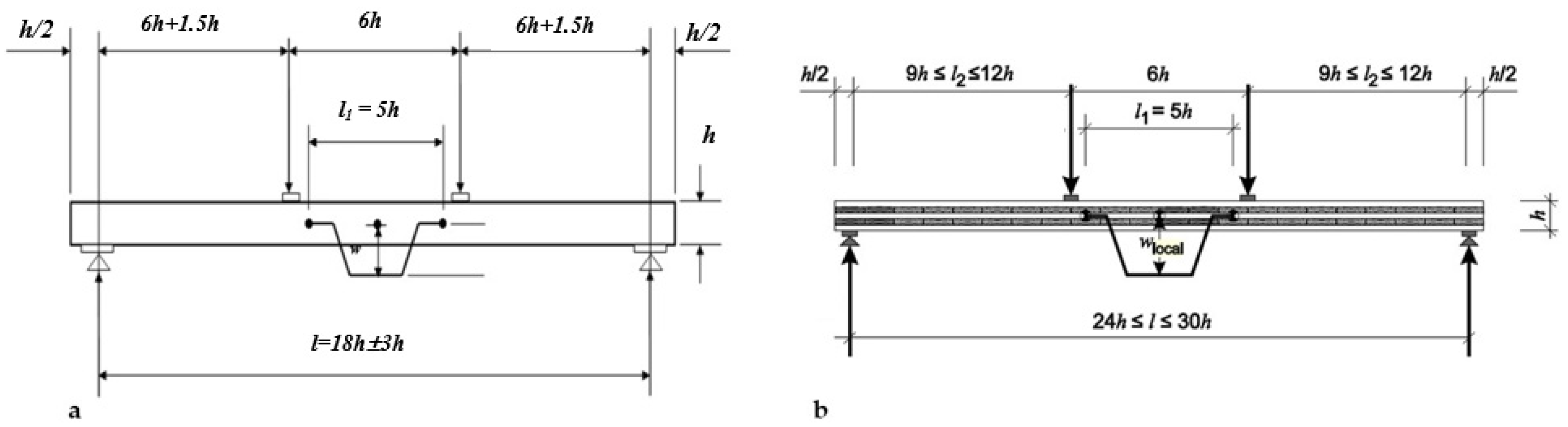
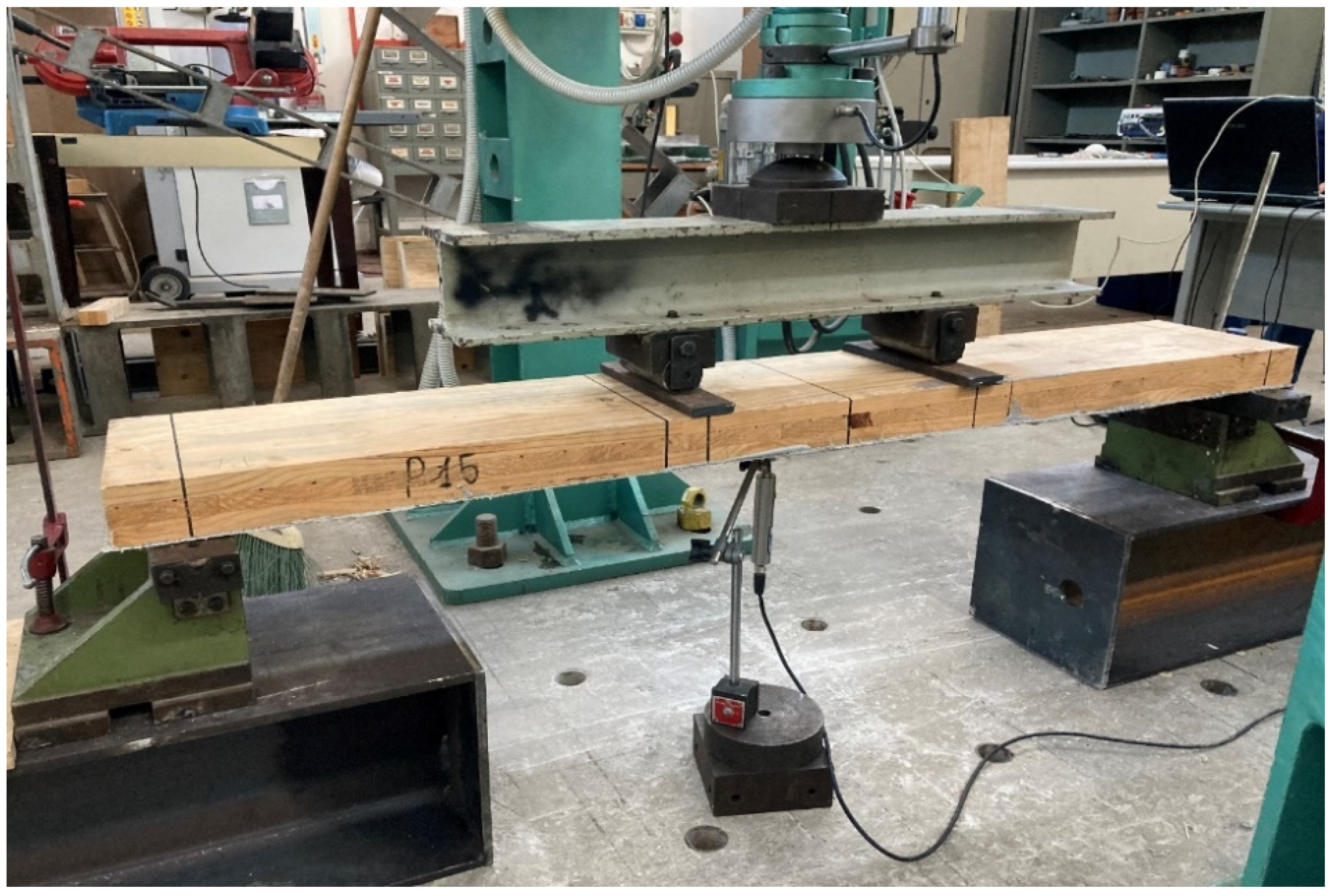
2.2. Bending Test
- 3 unreinforced panels (U), sized 1200 × 240 × 60 mm (L × W × h);
- 8 panels reinforced with a single SRP layer (R), sized 1200 × 240 × 60 mm;
- 3 panels reinforced with a double SRP layer (RR), sized 1200 × 240 × 60 mm;
- 2 panels reinforced with a double SRP layer (RR), sized 1500 × 240 × 60 mm;
- 4 panels reinforced with a double-weight SRP single layer (RR*), sized 1500 × 240 × 60 mm.
- Fu = failure load (N);
- wmax = maximum vertical displacement (mm) corresponding to the peak load;
- (F-w) = dataset of forces (F) and vertical displacements (w) recorded via the force and displacement transducers for tracking the load–displacement curves.
- h = total height of the specimen;
- Jeff = effective moment of inertia of the CLT panel.
- Ji = moment of inertia of the generic 0°-oriented layer i;
- Ai = cross-sectional area of the generic 0°-oriented layer i;
- zi = the distance between the centroid of the generic 0°-oriented layer i and the CLT section centroid.
- (F2 − F1) = load increment (N) on the regression line with a correlation coefficient of 0.99 or better;
- (w2 − w1) = vertical displacement increment (mm) corresponding to (F2 − F1);
- l = span of the specimen between the supports;
- b = width of the specimen;
- G0 = timber shear modulus in the direction parallel to the grain (N/mm2).
3. Results
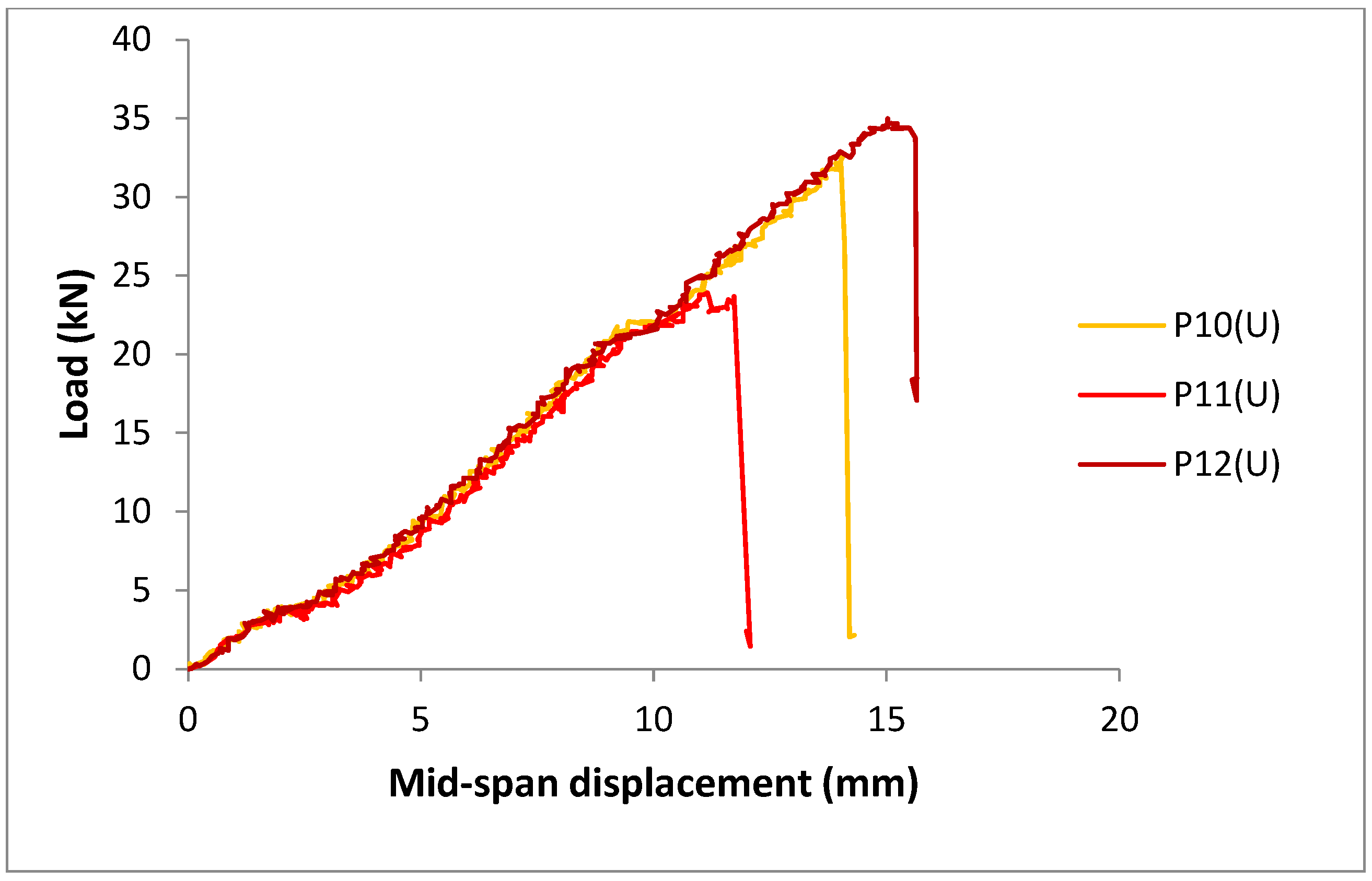
3.1. Unreinforced Panels (U)
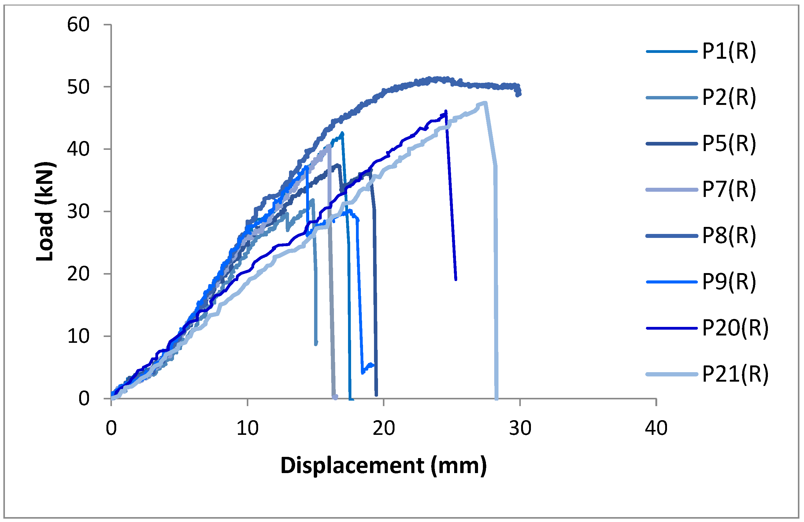
3.2. Single-Layer Reinforced Panels (R)
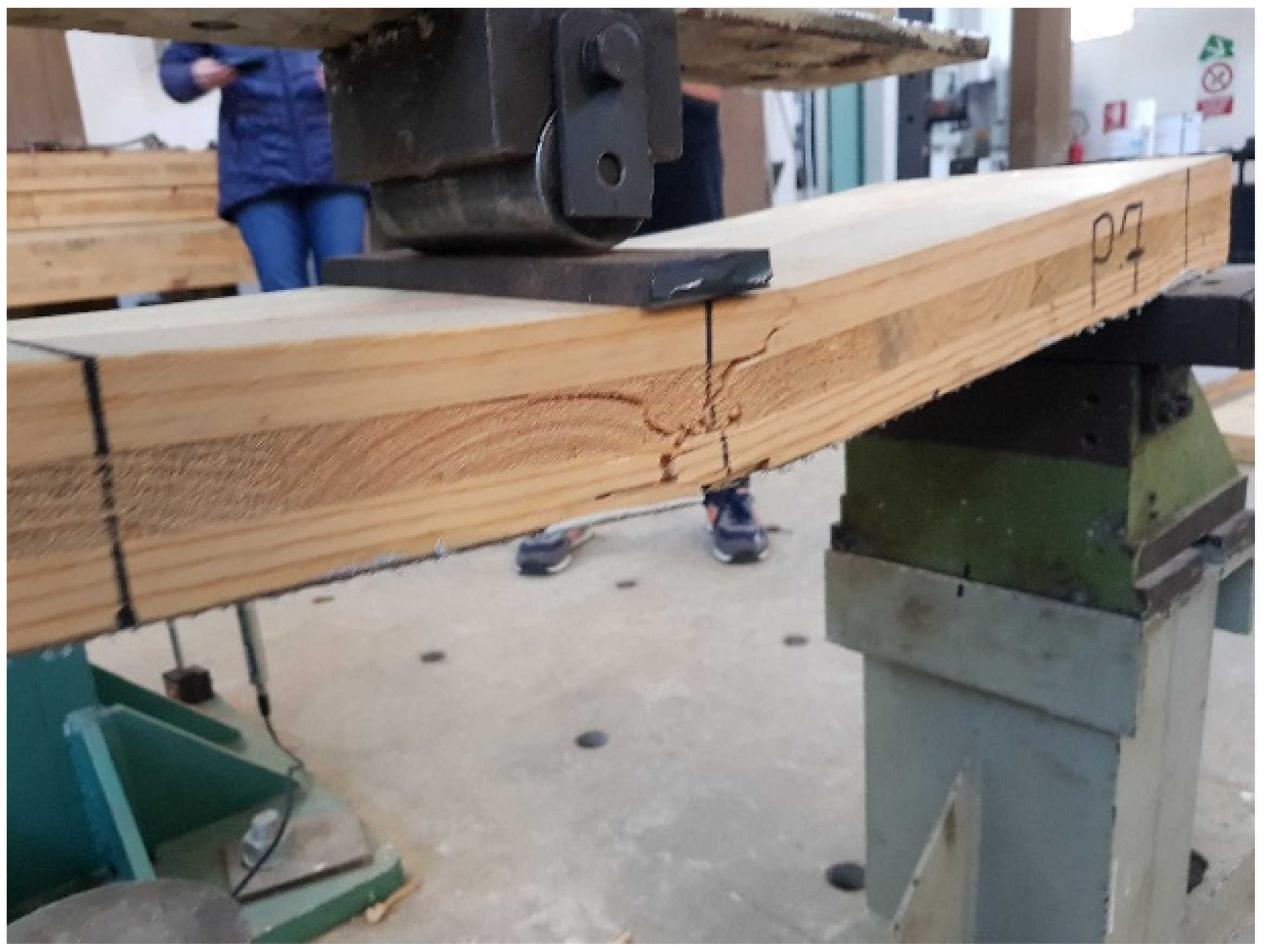
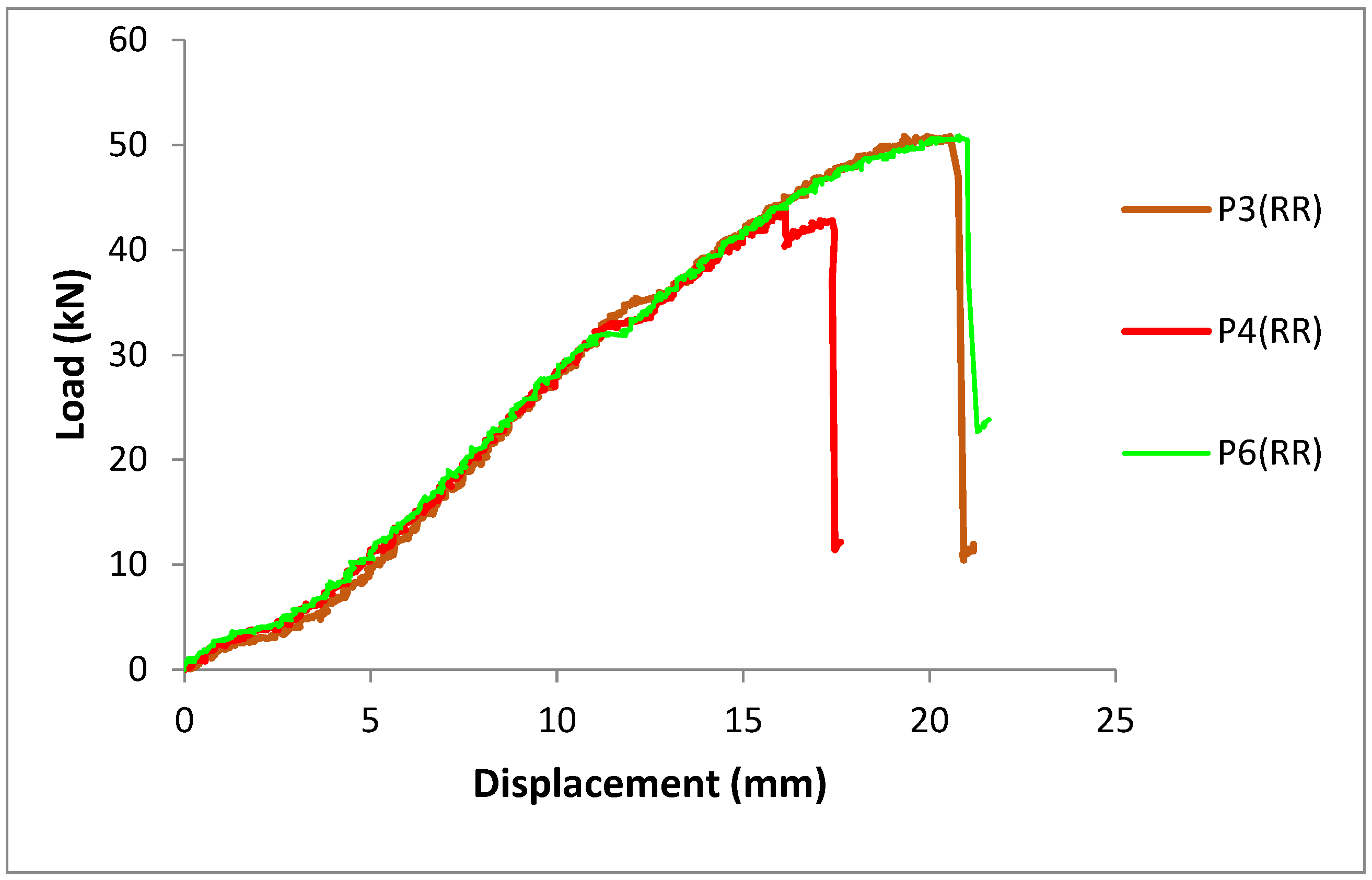
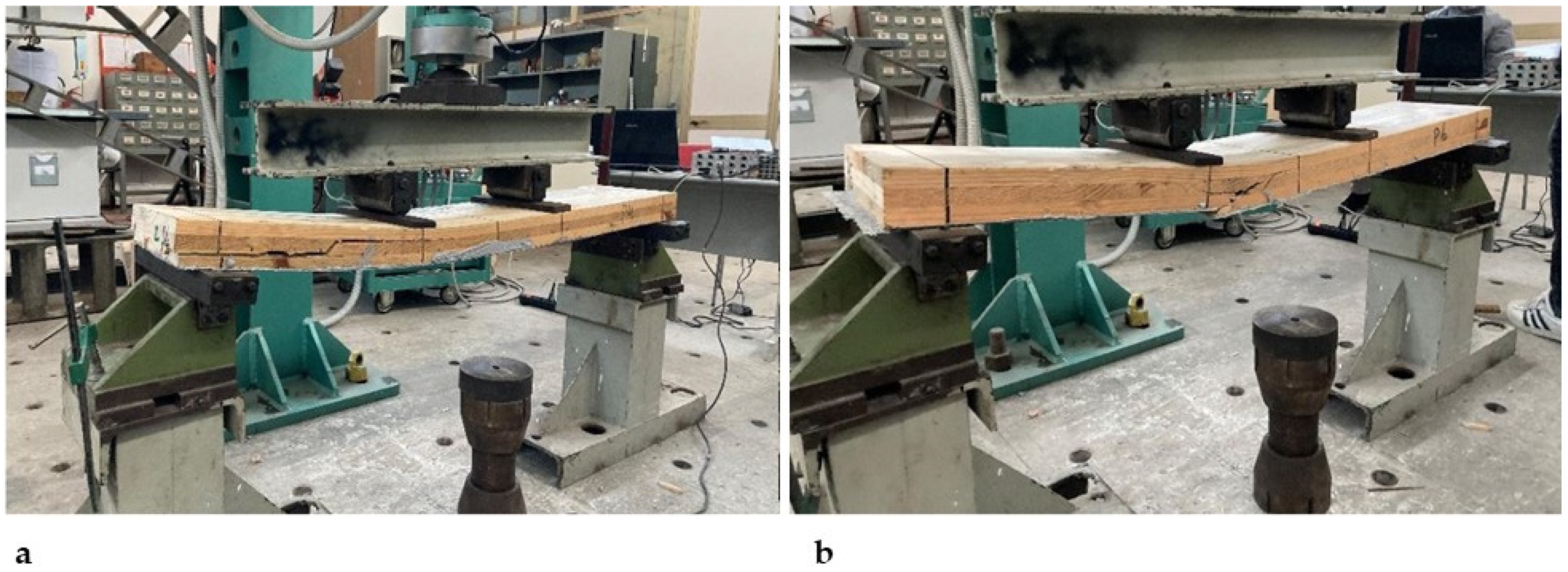
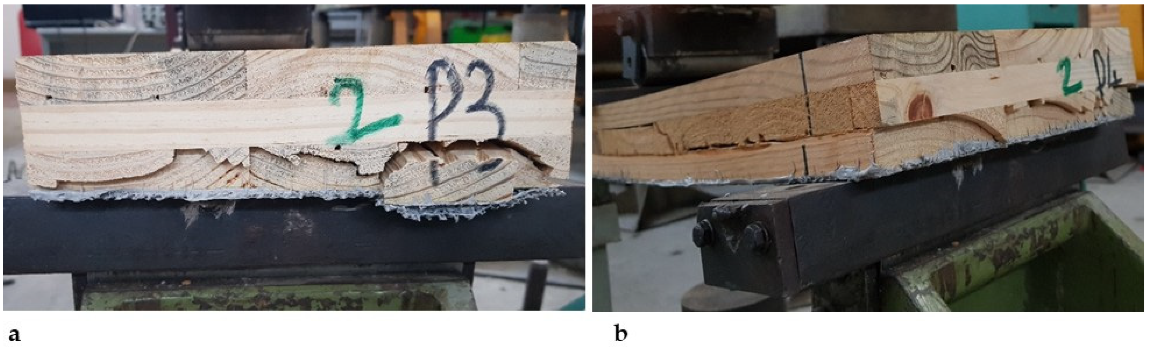
3.3. Double-Reinforced Panels (RR and RR*)
4. Discussion
5. Analytical Model
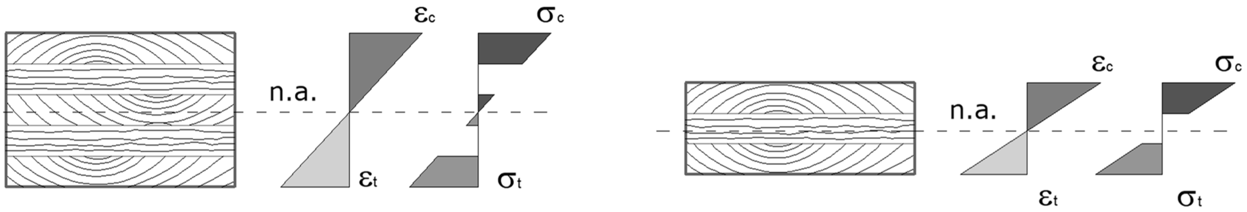
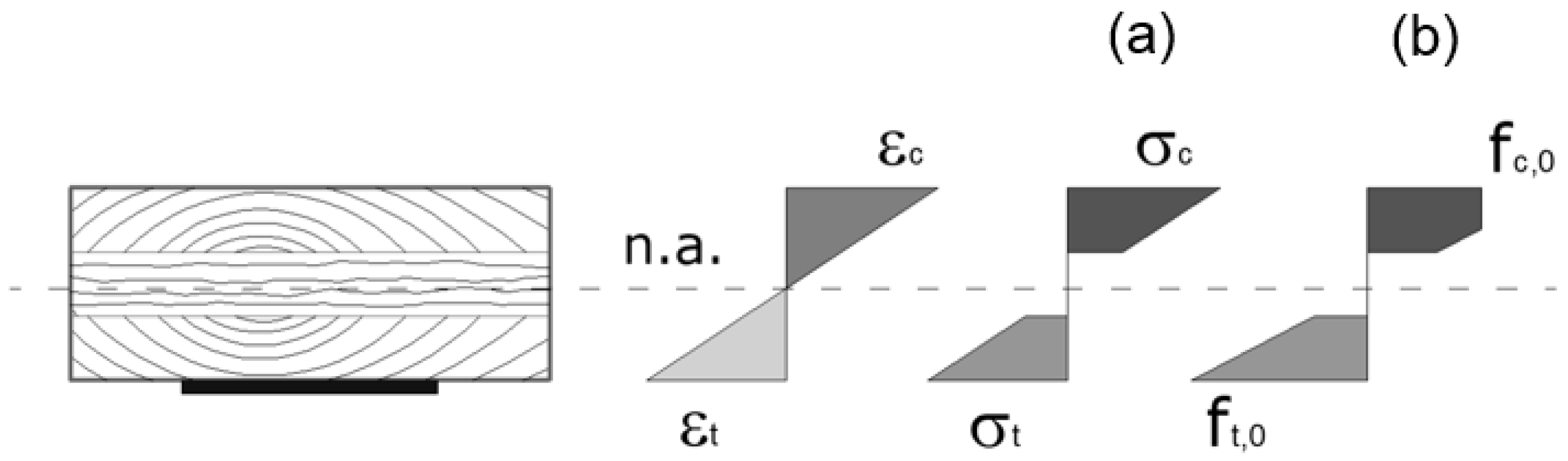
5.1. Timber Constitutive Behavior
- Planar section under loading.
- Full composite behavior.
5.2. SRP Reinforcement Behavior
5.3. Capacity Model
- tensile failure without plasticity in the compression edge: εt = εtu and εc ≤ εcy
- tensile failure with plasticity in the compression edge: εt = εtu and εcy ≤ εc ≤ εcu
5.4. Comparison to Experimental Results
6. Conclusions
- Three unreinforced panels (U), sized 1200 × 240 × 60 mm (L × W × h).
- Eight panels reinforced with single SRP layer (R), sized 1200 × 240 × 60 mm.
- Three panels reinforced with double SRP layer (RR), sized 1200 × 240 × 60 mm.
- Two panels reinforced with double SRP layer (RR), sized 1500 × 240 × 60 mm.
- Four panels reinforced with double-weight SRP single layer (RR*), sized 1500 × 240 × 60 mm.
- Compared to unreinforced panels, the SRP single-layer reinforced panels show an increase in bending strength and bending stiffness on average equal to 37.0% and 12.2%, respectively, while the double-layer reinforced panels show an increase in bending strength and bending stiffness on average equal to 58.8% and 27.3%, respectively.
- The increase in bending strength due to the reinforcement favors the increase in shear stresses and the possible occurrence of failure due to rolling shear. This is particularly evident in the case of double-layer reinforcement.
- Since the strength improvement induced by the reinforcement is not proportional to its amount, and the increase in the amount of reinforcement increases the possibility of shear failures, the convenience of double-layer reinforcement must be carefully evaluated in the design phase, as the rolling shear failures can set the limit of the possible panel strengthening.
- The strength and stiffness enhancement provided by the double-layer and double-weight reinforcements confirms the substantial equivalence, except in terms of the ductility, of the two reinforcement systems.
Author Contributions
Funding
Institutional Review Board Statement
Informed Consent Statement
Data Availability Statement
Conflicts of Interest
References
- EN 338:2016; Structural Timber—Strength Classes. European Committee for Standardization: Brussels, Belgium, 2016.
- EN 14081-1:2016+A1:2019; Timber Structures—Strength Graded Structural Timber with Rectangular Cross Section—Part 1: General Requirements. European Committee for Standardization: Brussels, Belgium, 2019.
- EN 14081-2:2018+A1:2022; Timber Structures—Strength Graded Structural Timber with Rectangular Cross Section—Part 2: Machine Grading; Additional Requirements for Type Testing. European Committee for Standardization: Brussels, Belgium, 2022.
- EN 14081-3:2022; Timber Structures—Strength Graded Structural Timber with Rectangular Cross Section—Part 3: Machine Grading; Additional Requirements for Factory Production Control. European Committee for Standardization: Brussels, Belgium, 2022.
- Türer, A.; Dönmez, Ü.; Çevik, A.; Anıl, Ö. Behavior of CLT Formwork Beams Retrofitting with CFRP Strip under Static Loading. In Proceedings of the 2nd International Symposium on Innovative Approaches in Scientific Studies (ISAS2018-Winter), Samsun, Turkey, 30 November–2 December 2018; SETSCI Conference Proceedings. Volume 3, pp. 277–281. [Google Scholar]
- Song, Y.-J.; Lee, I.-H.; Song, D.-B.; Hong, S.-I. Evaluation of Delamination and Bending Performance of Composite CLT Reinforced with CFRP. Wood Fiber Sci. 2019, 51, 354–363. [Google Scholar] [CrossRef]
- Lv, Q.; Wang, W.; Liu, Y. Flexural Performance of Cross-Laminated Bamboo (CLB) Slabs and CFRP Grid Composite CLB Slabs. Hindawi Adv. Civ. Eng. 2019, 2019, 6980782. [Google Scholar] [CrossRef]
- Lopez-Molina, A.; Doudak, G. Retrofit techniques for Cross-Laminated Timber (CLT) elements subjected to blast loads. Eng. Struct. 2019, 197, 109450. [Google Scholar] [CrossRef]
- Song, Y.-J.; Lee, I.-H.; Hong, S.-I. An Evaluation of Strength Performance of the Edge Connections between Cross-laminated Timber Panels Reinforced with Glass Fiber-reinforced Plastic. BioResources 2019, 14, 7719–7733. [Google Scholar] [CrossRef]
- Valdes, M.; Giaccu, G.F.; Meloni, D.; Concu, G. Reinforcement of maritime pine cross-laminated timber panels by means of natural flax fibers. Constr. Build. Mater. 2020, 233, 117741. [Google Scholar] [CrossRef]
- Haftkhani, A.R.; Shakiba, S. Reinforcement of flexural performance of screwed cross laminated timber (CLT) panels constructed of poplar by aluminum sheet and glass fiber reinforced polymer wrap. For. Wood Prod. 2020, 73, 317–331. [Google Scholar] [CrossRef]
- Bhat, J.A. Improved Strength and Stiffness Characteristics of Cross-laminated Poplar Timber Columns. Int. J. Eng. Trans. A Basics 2021, 34, 803–810. [Google Scholar] [CrossRef]
- Sharari, M.; Haftkhani, A.R.; Ahmadi, M.; Moezipour, B.; Hajializadeh, F. Strengthening of the cross-laminated timber using glass fiber-reinforced polymer on the lateral performance of the single shear lap joints. Iran. J. Wood Pap. Ind. 2022, 13, 1–14. [Google Scholar]
- Rostampour Haftkhani, A.; Rashidi, M.; Abdoli, F.; Gerami, M. The Effect of GFRP Wrapping on Lateral Performance of Double Shear Lap Joints in Cross-Laminated Timber as a Part of Timber Bridges. Buildings 2022, 12, 1678. [Google Scholar] [CrossRef]
- Rostampour-Haftkhani, A.; Abdoli, F.; Arabi, M.; Nasir, V.; Rashidi, M. Effect of Wood Densification and GFRP Reinforcement on the Embedment Strength of Poplar CLT. Appl. Sci. 2023, 13, 12249. [Google Scholar] [CrossRef]
- Li, H.; Wang, L.; Wei, Y.; Semple, K.E.; Dai, C. Out-of-plane bending behavior of cross-laminated timber members enhanced with fiber-reinforced polymers. J. Build. Eng. 2023, 66, 105862. [Google Scholar] [CrossRef]
- Arabi, M.; Rostampour Haftkhani, A. Improved withdrawal capacity of nail and screw in cross-laminated timber (CLT) made of poplar (Populus alba) using glass fiber-reinforced polymer (GFRP). J. For. Wood Prod. 2023, 76, 23–32. [Google Scholar]
- Swinea, J.; Sanborn, K.; Weaver, M.; Lo Ricco, M.; Adam Senalik, C.; Stewart, L.K. Enhanced cross laminated timber (ECLT) for ballistic resistant design. Int. J. Impact Eng. 2024, 189, 104931. [Google Scholar] [CrossRef]
- Baek, S.; Song, Y.; Hong, S. Bending performance of domestic larch cross-laminated timber reinforced with fiber-reinforced polymer. Wood Mater. Sci. Eng. 2025, 20, 686–696. [Google Scholar] [CrossRef]
- Casadei, P.; Nanni, A.; Alkhrdaji, T. Steel-Reinforced Polymer: An Innovative and Promising Material for Strengthening the Infrastructures. Concr. Eng. Int. 2005, 9, 54–56. [Google Scholar]
- De Santis, S.; de Felice, G.; Napoli, A.; Realfonzo, R. Strengthening of structures with Steel Reinforced Polymers: A state-of-the-art review. Compos. Part B Eng. 2016, 104, 87–110. [Google Scholar] [CrossRef]
- Napoli, A.; de Felice, G.; De Santis, S.; Realfonzo, R. Bond behaviour of Steel Reinforced Polymer strengthening systems. Compos. Struct. 2016, 152, 499–515. [Google Scholar] [CrossRef]
- Krzywoń, R. Steel-Reinforced Polymers and Steel-Reinforced Composite Mortars for Structural Applications—An Overview. J. Compos. Sci. 2020, 4, 142. [Google Scholar] [CrossRef]
- Krzywoń, R. Assessment of Existing Bond Models for Externally Bonded SRP Composites. Appl. Sci. 2020, 10, 8593. [Google Scholar] [CrossRef]
- Ascione, F.; Lamberti, M.; Napoli, A.; Razaqpur, A.G.; Realfonzo, R. Modeling SRP-concrete interfacial bond behavior and strength. Eng. Struct. 2019, 187, 220–230. [Google Scholar] [CrossRef]
- Li, J.; Wu, C.; Hao, H.; Su, Y. Experimental and numerical study on steel wire mesh reinforced concrete slab under contact explosion. Mater. Des. 2017, 116, 77–91. [Google Scholar] [CrossRef]
- Napoli, A.; Realfonzo, R. Compressive behavior of concrete confined by SRP wraps. Constr. Build. Mater. 2016, 127, 993–1008. [Google Scholar] [CrossRef]
- Ascione, F.; Lamberti, M.; Napoli, A.; Razaqpur, G.; Realfonzo, R. An experimental investigation on the bond behavior of steel reinforced polymers on concrete substrate. Compos. Struct. 2017, 181, 58–72. [Google Scholar] [CrossRef]
- Hawileh, R.A.; Nawaz, W.; Abdalla, J.A. Flexural behavior of reinforced concrete beams externally strengthened with Hardwire Steel-Fiber sheets. Constr. Build. Mater. 2018, 172, 562–573. [Google Scholar] [CrossRef]
- Ascione, F.; Napoli, A.; Realfonzo, R. Experimental and analytical investigation on the bond of SRP systems to concrete. Compos. Struct. 2020, 242, 112090. [Google Scholar] [CrossRef]
- Al Nuaimi, N.; Sohail, M.G.; Hawileh, R.A.; Abdalla, J.A.; Douier, K. Durability of reinforced concrete beams strengthened by galvanized steel mesh-epoxy systems under harsh environmental conditions. Compos. Struct. 2020, 249, 112547. [Google Scholar] [CrossRef]
- Bonati, A.; Franco, A.; Occhiuzzi, A. Long-Term Behaviour of Steel Reinforced Polymer (SRP) Systems Bonded to Concrete Substrates. In Proceedings of the Italian Concrete Conference 2020/21; di Prisco, M., Menegotto, M., Eds.; ICC 2021, Lecture Notes in Civil Engineering; Springer: Cham, Switzerland, 2024; Volume 351. [Google Scholar] [CrossRef]
- Al-Khafaji, A.F.; Myers, J.J.; Wang, W. Bond assessment of two types of SRP strengthening systems subjected to severe conditions. Constr. Build. Mater. 2021, 273, 121968. [Google Scholar] [CrossRef]
- Baietti, G.; Kahangi Shahreza, S.; Santandrea, M.; Carloni, C. Concrete columns confined with SRP: Effect of the size, cross-sectional shape and amount of confinement. Constr. Build. Mater. 2021, 275, 121618. [Google Scholar] [CrossRef]
- Sohail, M.G.; Al Nuaimi, N.; Hawileh, R.A.; Abdalla, J.A.; Douier, K. Durability of plain concrete prism strengthened with galvanized steel mesh and CFRP laminates under harsh environmental conditions. Constr. Build. Mater. 2021, 286, 122904. [Google Scholar] [CrossRef]
- Bencardino, F.; Nisticò, M. A Theoretical Model for Debonding Prediction in the RC Beams Externally Strengthened with Steel Strip and Inorganic Matrix. Materials 2021, 14, 4961. [Google Scholar] [CrossRef]
- Sneed, L.H.; Verre, S.; Ombres, L.; Carloni, C. Flexural behavior RC beams strengthened and repaired with SRP composite. Eng. Struct. 2022, 258, 114084. [Google Scholar] [CrossRef]
- Kekez, S.; Krzywon, R. Prediction of Bonding Strength of Externally Bonded SRP Composites Using Artificial Neural Networks. Materials 2022, 15, 1314. [Google Scholar] [CrossRef] [PubMed]
- Zou, X.; McBurney, K.L.; Sneed, L.H. A spike-shaped anchorage for steel reinforced polymer (SRP)-strengthened concrete structures. Constr. Build. Mater. 2023, 389, 131710. [Google Scholar] [CrossRef]
- Parsekian, G.A.; El-Hacha, R.; Shrive, N.G. Strengthening and Retrofitting Unreinforced Masonry Walls with Various FRP Systems. In Proceedings of the Asia-Pacific Conference on FRP in Structures (APFIS 2007), Hong Kong, China, 12–14 December 2007; pp. 263–270. [Google Scholar]
- Capozucca, R. Experimental FRP/SRP–historic masonry delamination. Compos. Struct. 2010, 92, 891–903. [Google Scholar] [CrossRef]
- Grande, E.; Imbimbo, M.; Sacco, E. Bond Behavior of Historical Clay Bricks Strengthened with Steel Reinforced Polymers (SRP). Materials 2011, 4, 585–600. [Google Scholar] [CrossRef]
- Valluzzi, M.R.; Oliveira, D.V.; Caratelli, A.; Castori, G.; Corradi, M.; De Felice, G.; Garbin, E.; Garcia, D.; Garmendia, L.; Grande, E.; et al. Round Robin Test for composite-to-brick shear bond characterization. Mater. Struct. 2012, 45, 1761–1791. [Google Scholar] [CrossRef]
- Girardello, P.; Pappas, A.; da Porto, F.; Valluzzi, M.R. Experimental testing and numerical modelling of masonry vaults. In Proceedings of the International Conference on Rehabilitation and Restoration of Structures, Chennai, India, 13–16 February 2013. [Google Scholar]
- Valluzzi, M.R.; da Porto, F.; Garbin, E.; Panizza, M. Out-of-plane behaviour of infill masonry panels strengthened with composite materials. Mater. Struct. 2014, 47, 2131–2145. [Google Scholar] [CrossRef]
- Garmendia, L.; Larrinaga, P.; San-Mateos, R.; San-José, J.T. Strengthening masonry vaults with organic and inorganic composites: An experimental approach. Mater. Des. 2015, 85, 102–114. [Google Scholar] [CrossRef]
- De Felice, G.; Aiello, M.A.; Bellini, A.; Ceroni, F.; De Santis, S.; Garbin, E.; Leone, M.; Lignola, G.P.; Malena, M.; Mazzotti, C.; et al. Experimental characterization of composite-to-brick masonry shear bond. Mater. Struct. 2016, 49, 2581–2596. [Google Scholar] [CrossRef]
- Gentilini, C.; Yuan, Y.; Carloni, C.; Franzoni, E. Adhesion between SRP and masonry: Laboratory simulations of the field moisture and salt conditions. Constr. Build. Mater. 2020, 264, 120697. [Google Scholar] [CrossRef]
- Garcia-Ramonda, L.; Pelà, L.; Roca, P.; Camata, G. Experimental cyclic behaviour of shear masonry walls reinforced with single and double layered Steel Reinforced Grout. Constr. Build. Mater. 2022, 320, 126053. [Google Scholar] [CrossRef]
- Ombres, L.; Guglielmi, M.; Verre, S. Structural Performances of Clay Brick Masonry Columns Partially Confined with FRCM/SRG Composites. Key Eng. Mater. 2022, 916, 297–304. [Google Scholar] [CrossRef]
- Jahangir, H.; Esfahani, M.R. Bond Behavior Investigation Between Steel Reinforced Grout Composites and Masonry Substrate. Iran. J. Sci. Technol. Trans. Civ. Eng. 2022, 46, 3519–3535. [Google Scholar] [CrossRef]
- Garcia-Ramonda, L.; Pelà, L.; Roca, P.; Camata, G. Experimental and numerical insights on the in-plane behaviour of unreinforced and TRM/SRG retrofitted brick masonry walls by diagonal compression and shear-compression testing. Constr. Build. Mater. 2023, 402, 132997. [Google Scholar] [CrossRef]
- Al-Jaberi, Z.; Myers, J.J. Prediction of compressive strength and evaluation of different theoretical standards and proposed models of brick columns confined with FRP, FRCM, or SRG system. Case Stud. Constr. Mater. 2023, 18, e01875. [Google Scholar] [CrossRef]
- Pingaro, N.; Milani, G. Simple non-linear numerical modelling of masonry arches reinforced with SRG using elasto-fragile and elasto-ductile truss finite elements. Eng. Struct. 2023, 293, 116637. [Google Scholar] [CrossRef]
- Canestri, M.; Ferretti, F.; Mazzotti, C. Confinement of masonry columns through SRG: Experimental results and analytical prediction. Procedia Struct. Integr. 2023, 44, 2198–2205. [Google Scholar] [CrossRef]
- Borri, A.; Corradi, M. Strengthening of timber beams with high strength steel cords. Compos. Part B Eng. 2011, 42, 1480–1491. [Google Scholar] [CrossRef]
- Corradi, M.; Maheri, A.; Osofero, A.I. Design of reinforced and unreinforced timber beams subject to uncertainties. In Proceedings of the Twelfth International Conference on Computational Structures Technology, Naples, Italy, 2–5 September 2014; Topping, B.H.V., Iványi, P., Eds.; Civil Comp Press: Stirlingshire, UK, 2014; p. 134. [Google Scholar] [CrossRef]
- Uzel, M.; Togay, A.; Anil, Ö.; Söğütlü, C. Experimental investigation of flexural behavior of glulam beams reinforced with different bonding surface materials. Constr. Build. Mater. 2018, 158, 149–163. [Google Scholar] [CrossRef]
- Ulasan, H.; Bajraktari, A.; Döngel, N.; Imirzi, H.Ö.; Sögütlü, C. Modulus of Elasticity and Flexural Behavior of Glulam Beams Reinforced with Steel Mesh in Different Mesh Openings. Materials 2023, 16, 4307. [Google Scholar] [CrossRef]
- Song, Y.S.; Youn, J.R.; Gutowski, T.G. Life cycle energy analysis of fiber-reinforced composites. Compos. Part A Appl. Sci. Manuf. 2009, 40, 1257–1265. [Google Scholar] [CrossRef]
- EN 408:2010+A1:2012; Timber Structures—Structural Timber and Glued Laminated Timber—Determination of Some Physical and Mechanical Properties. European Committee for Standardization: Brussels, Belgium, 2012.
- EN 16351:2021; Timber Structures—Cross Laminated Timber—Requirements. European Committee for Standardization: Brussels, Belgium, 2021.
- Canadian CLT Handbook, 2019 ed; FPInnovations: Point-Claire, QC, Canada, 2019; Volume I, Special Publication SP-532E; ISBN 978-0-86488-590-6.
- Blass, H.J.; Fellmoser, P. Design of solid wood panels with cross layers. In Proceedings of the 8th World Conference on Timber Engineering 2004, Lahti, Finland, 14–17 June 2004. [Google Scholar]
- EN 384:2022; Structural Timber—Structural Timber—Determination of Characteristic Values of Mechanical Properties and Density. European Committee for Standardization: Brussels, Belgium, 2022.
- Riu, R. Caratterizzazione di Pannelli XLam in Pino Marittimo Sardo. Ph.D. Thesis, University of Cagliari, Cagliari, Italy, 2016. (In Italian). [Google Scholar]
- Concu, G.; Giaccu, G.F.; Meloni, D.; Valdes, M.; Riu, R. Advances in reinforcing of cross laminated timber panels. In Proceedings of the WCTE 2021, World Conference on Timber Engineering, Santiago, Chile, 9–12 August 2021. [Google Scholar]
- CNR-DT 201-2005; Preliminary Studies Addressed to Drawing Up Guidelines for Static Consolidation Interventions on Timber Structures by Means of Fiber-Reinforced Composites. National Research Council: Rome, Italy, 2005.
- Bodig, J.; Jayne, B.A. Mechanics of Wood and Wood Composites; Van Nostrand Reinhold: New York, NY, USA, 1982. [Google Scholar]
- Borri, A.; Corradi, M.; Grazini, A. A method for flexural reinforcement of old wood beams with CFRP materials. Compos. Part B 2005, 36, 143–153. [Google Scholar] [CrossRef]
- Fiorelli, J.; Alves Dias, A. Analysis of the strength and stiffness of timber beams reinforced with carbon fiber and glass fiber. Mater. Res. 2003, 6, 193–202. [Google Scholar] [CrossRef]
- Xia, Q.; Xiang, P.; Jiang, L.; Yan, J.; Peng, L. Bending and free vibration and analysis of laminated plates on Winkler foundations based on meshless layerwise theory. Mech. Adv. Mater. Struct. 2021, 29, 6168–6187. [Google Scholar] [CrossRef]


| Label | Layer Thickness (mm) | Thickness (mm) | Width (mm) | Length (mm) | Weight (g) | Reinforcement (U/R/RR/RR*) |
|---|---|---|---|---|---|---|
| P1 | 20 | 60 | 240 | 1200 | 8680 | R |
| P2 | 20 | 60 | 240 | 1200 | 8666 | R |
| P3 | 20 | 60 | 242 | 1200 | 8613 | RR |
| P4 | 20 | 60 | 240 | 1200 | 8547 | RR |
| P5 | 20 | 60 | 240 | 1200 | 8617 | R |
| P6 | 20 | 60 | 240 | 1200 | 8710 | RR |
| P7 | 20 | 60 | 240 | 1200 | 8793 | R |
| P8 | 20 | 60 | 240 | 1200 | 8761 | R |
| P9 | 20 | 60 | 242 | 1200 | 8878 | R |
| P10 | 20 | 60 | 240 | 1201 | 8322 | U |
| P11 | 20 | 60 | 241 | 1200 | 8411 | U |
| P12 | 20 | 60 | 240 | 1200 | 8435 | U |
| P13 | 20 | 60 | 240 | 1500 | 10,213 | RR |
| P15 | 20 | 60 | 238 | 1500 | 10,276 | RR |
| P16 | 20 | 60 | 241 | 1500 | 11,013 | RR* |
| P17 | 20 | 60 | 241 | 1500 | 11,247 | RR* |
| P18 | 20 | 60 | 242 | 1500 | 11,090 | RR* |
| P19 | 20 | 60 | 243 | 1500 | 11,730 | RR* |
| P20 | 20 | 60 | 243 | 1200 | 8685 | R |
| P21 | 20 | 60 | 242 | 1200 | 8354 | R |
| Feature | GeoSteel SRP G600 System Performance | GeoSteel SRP G1200 System Performance | |
|---|---|---|---|
| Characteristic tensile strength (fy,k) | 1 layer | ≥3073 MPa | ≥2805 MPa |
| 3 layers | ≥3013 MPa | ≥2887 MPa | |
| Characteristic tensile strain (εfu) | 1 layer | ≥0.015 mm/mm | ≥0.015 mm/mm |
| 3 layers | ≥0.015 mm/mm | ≥0.015 mm/mm | |
| Mean elastic modulus in tension (Ef) | 1 layer | ≥210,000 MPa | ≥226,000 MPa |
| 3 layers | ≥204,000 MPa | ≥207,000 MPa | |
| Tensile strength in overlapping | Overlapping length = 200 mm (1 layer) | ≥2800 MPa | ≥2698 MPa |
| Label | Span l (mm) | Fu (kN) | Vu (kN) | Mu (kNm) | fm (N/mm2) | τmax (N/mm2) | wmax (mm) | (EJ)exp (Nm2) | Failure Mode |
|---|---|---|---|---|---|---|---|---|---|
| P10 | 1080 | 32.49 | 16.24 | 5.85 | 42.17 | 1.57 | 14.05 | 38,292 | Bending |
| P11 | 1080 | 23.91 | 11.96 | 4.30 | 30.91 | 1.15 | 11.15 | 38,354 | Bending |
| P12 | 1080 | 34.98 | 17.49 | 6.30 | 45.41 | 1.69 | 15.03 | 37,575 | Bending |
| Average | 30.46 | 15.23 | 5.48 | 39.50 | 1.47 | 13.41 | 38,074 | ||
| St. dev. | 5.81 | 2.90 | 1.05 | 7.61 | 0.28 | 2.02 | 433 | ||
| Label | Span l (mm) | Fu (kN) | Vu (kN) | Mu (kNm) | fm (N/mm2) | τmax (N/mm2) | wmax (mm) | (EJ)exp (Nm2) | Failure Mode |
|---|---|---|---|---|---|---|---|---|---|
| P1 | 1080 | 42.65 | 21.33 | 7.68 | 55.36 | 1.99 | 16.96 | 42,380 | Bending |
| P2 | 1080 | 31.86 | 15.93 | 5.73 | 41.36 | 1.49 | 14.81 | 39,606 | Bending |
| P5 | 1080 | 37.48 | 18.74 | 6.75 | 48.65 | 1.75 | 16.59 | 40,568 | Bending |
| P7 | 1080 | 40.55 | 20.28 | 7.30 | 52.64 | 1.89 | 16.02 | 40,510 | RS |
| P8 | 1080 | 51.71 | 25.85 | 9.31 | 67.12 | 2.41 | 24.14 | 47,308 | Bending |
| P9 | 1080 | 37.21 | 18.60 | 6.70 | 47.90 | 1.73 | 14.26 | 45,027 | Bending |
| P20 | 1080 | 46.15 | 23.08 | 8.31 | 59.17 | 2.15 | 24.56 | 44,861 | Bending |
| P21 | 1080 | 47.21 | 23.60 | 8.50 | 60.77 | 2.20 | 27.38 | 41,609 | Bending |
| Average | 41.85 | 20.93 | 7.53 | 54.12 | 1.95 | 19.34 | 42,734 | ||
| St. dev. | 6.41 | 3.20 | 1.15 | 8.23 | 0.30 | 5.15 | 2713 | ||
| Label | Span l (mm) | Fu (kN) | Vu (kN) | Mu (kNm) | fm (N/mm2) | τmax (N/mm2) | wmax (mm) | (EJ)exp (Nm2) | Failure Mode |
|---|---|---|---|---|---|---|---|---|---|
| P3 | 1080 | 50.82 | 25.41 | 9.15 | 65.42 | 2.31 | 19.94 | 51,086 | RS |
| P4 | 1080 | 43.69 | 21.84 | 7.86 | 56.71 | 1.99 | 16.13 | 47,249 | RS |
| P6 | 1080 | 50.87 | 25.43 | 9.16 | 66.03 | 2.31 | 20.81 | 47,088 | Bending |
| Average | 48.46 | 24.23 | 8.72 | 62.72 | 2.20 | 18.96 | 48,474 | ||
| St. dev. | 4.13 | 2.07 | 0.75 | 5.21 | 0.18 | 2.49 | 2263 | ||
| P13 | 1380 | 30.81 | 15.40 | 7.86 | 56.55 | 1.40 | 40,43 | 42,910 | Bending |
| P15 | 1380 | 30.79 | 15.40 | 7.85 | 57.11 | 1.40 | 35,04 | 49,362 | Bending |
| Average | 30.80 | 15.40 | 7.85 | 56.88 | 1.40 | 37.73 | 46,136 | ||
| St. dev. | 0.01 | 0.00 | 0.01 | 0.40 | 0.00 | 3.81 | 4562 | ||
| P16 | 1380 | 34.44 | 17.22 | 8.78 | 63.07 | 1.57 | 63.77 | 46,491 | Bending |
| P17 | 1380 | 39.55 | 19.77 | 10.09 | 72.43 | 1.80 | 84.88 | 47,222 | Bending |
| P18 | 1380 | 30.84 | 15.42 | 7.86 | 56.25 | 1.40 | 44.49 | 41,495 | Bending |
| P19 | 1380 | 33.71 | 16.85 | 8.60 | 61.22 | 1.53 | 30.14 | 58,680 | RS |
| Average | 34.64 | 17.32 | 8.83 | 63.24 | 1.58 | 55.82 | 48,472 | ||
| St. dev. | 3.63 | 1.81 | 0.93 | 6.77 | 0.17 | 23.77 | 7266 | ||
| SRP Reinforcement | Span l (mm) | Av. Mu (kN/m) | Av. fm (N/mm2) | % fm incr. | Av. (EJ)exp (Nm2) | % (EJ)exp Incr. | |
|---|---|---|---|---|---|---|---|
| U | 1080 | 5.48 | 39.50 | / | 38,074 | / | |
| R | 1080 | 7.53 | 54.12 | 37.0% | 42,734 | 12.2% | |
| RR | 1080 | 8.72 | 62.72 | 58.8% | 48,474 | 27.3% | |
| RR | 1380 | 7.85 | 56.88 | 44.0% | 45,574 | 19.7% | |
| RR* | 1380 | 8.83 | 63.24 | 60.1% | 48,472 | 27.3% | |
| Student’s t-Test | Statistical Significance Level | ||||||
| fm | (EJ)exp | ||||||
| U-R | 5% | <5% | |||||
| U-RR (1080) | <5% | <5% | |||||
| U-RR (1380) | <10% | >20% | |||||
| U-RR* | <5% | <5% | |||||
| ft,0 (N/mm2) | εtu % | fc,0 (N/mm2) | εcy % | εcu % | E0 (N/mm2) |
|---|---|---|---|---|---|
| 39.5 | 0.50 | 34.6 | 0.44 | 1.00 | 7850 |
| fyk (N/mm2) | εfu % | Ef (N/mm2) | tf mm |
|---|---|---|---|
| 3073 | 1.50 | 212,000 | 0.08 |
| Label | Mu,exp (kNm) | Mu,mod (kNm) | x (mm) | εc % | εt = εtu % | Error % |
|---|---|---|---|---|---|---|
| U | 5.48 | 5.48 | 30.23 | 0.52 | 0.50 | / |
| R | 7.57 | 6.43 | 32.58 | 0.60 | 0.50 | −15.1 |
| RR + RR* | 8.49 | 7.23 | 35.40 | 0.73 | 0.50 | −14.8 |
Disclaimer/Publisher’s Note: The statements, opinions and data contained in all publications are solely those of the individual author(s) and contributor(s) and not of MDPI and/or the editor(s). MDPI and/or the editor(s) disclaim responsibility for any injury to people or property resulting from any ideas, methods, instructions or products referred to in the content. |
© 2025 by the authors. Licensee MDPI, Basel, Switzerland. This article is an open access article distributed under the terms and conditions of the Creative Commons Attribution (CC BY) license (https://creativecommons.org/licenses/by/4.0/).
Share and Cite
Concu, G.; Meloni, D.; Valdes, M. Experimental Evaluation of the Effects of SRP Reinforcement on the Flexural Behavior of CLT Panels. Technologies 2025, 13, 271. https://doi.org/10.3390/technologies13070271
Concu G, Meloni D, Valdes M. Experimental Evaluation of the Effects of SRP Reinforcement on the Flexural Behavior of CLT Panels. Technologies. 2025; 13(7):271. https://doi.org/10.3390/technologies13070271
Chicago/Turabian StyleConcu, Giovanna, Daniel Meloni, and Monica Valdes. 2025. "Experimental Evaluation of the Effects of SRP Reinforcement on the Flexural Behavior of CLT Panels" Technologies 13, no. 7: 271. https://doi.org/10.3390/technologies13070271
APA StyleConcu, G., Meloni, D., & Valdes, M. (2025). Experimental Evaluation of the Effects of SRP Reinforcement on the Flexural Behavior of CLT Panels. Technologies, 13(7), 271. https://doi.org/10.3390/technologies13070271