Abstract
An anthropomorphic robot is a mechanical device designed to perform human-like tasks, such as manipulating objects, and has been one of the significant contributions in robotics over the past 60 years. This paper presents an advanced system for controlling a robotic arm using user hand gestures and movements. It eliminates the need for traditional sensors or physical controls by implementing an intuitive approach based on MediaPipe and computer vision. The system recognizes the user’s hand movements. It translates them into commands that are sent to a microcontroller, which operates a robotic hand equipped with six servomotors: five for the fingers and one for the wrist, which stands out for its orthonormal design that avoids occlusion problems in turns of up to 180°, guaranteeing precise wrist control. Unlike conventional systems, this approach uses only a 2D camera to capture movements, simplifying design and reducing costs. The proposed system allows replicating the user’s activity with high precision, expanding the possibilities of human-robot interaction. Notably, the system has been able to replicate the user’s hand gestures with an accuracy of up to 95%.
1. Introduction
Communication between humans and computers has posed a constant challenge. For over half a century, various methods have been explored to facilitate interaction with these devices and develop more efficient and accessible interfaces. In this context, sign and motion recognition has emerged as one of the most effective and popular solutions to optimize human-computer interaction (HCI) [1]. This technology enables computers to capture and interpret hand movements and hand signals, thus allowing the execution of commands intuitively. The growing popularity of motion and gesture recognition is due to its wide application in various areas, such as robot control, human-computer interaction, and the management of virtual environments, such as home automation, industrialization, and even surgery. Sign and motion recognition systems have evolved remarkably, standing out for their ability to interact efficiently with machines. In particular, electromyography (EMG) sign classification, for example, has proven to be an accurate method for identifying movements using electrodes placed on the skin or inserted into muscles; electromyography measures the electrical activity of muscle tissues [2,3,4].
The main approaches in hand gesture research fall into two categories: (A) those using sensor gloves and (B) those based on camera vision. Although colored gloves are also used to facilitate visual capture, human gesture recognition has multiple applications in various research areas, driven by the growing demand for more sustainable, intelligent, and reliable systems. It involves capturing digital images through cameras, which are then analyzed to identify hand movements [5,6].
As advances in robotics continue to integrate into our daily lives, scenarios in which humans and robots collaborate are expected to increase. Current research in human-robot interaction focuses on how both can work safely and cooperatively in the same environment, with the prospect of robots becoming fundamental building blocks for human prosthetics [7,8]. A crucial requirement to ensure the safety of these interactions is that robots can receive environmental data directly from humans, who provide such information in the first instance.
With advances in computer vision, a large amount of accurate data can be obtained using depth cameras and webcams. Visual sensors have been used to capture the location of objects manipulated by humans by operating a manipulator to perform selection and placement tasks using the position of objects [9,10]. Other studies have proposed using human skeleton algorithms to improve safety in human-robot interaction environments. These algorithms extract human skeletal features and assign real-time safety labels and training models to evaluate human postures. If the system detects dangerous actions, it interrupts the robot’s operation [11]. Inspired by studies over the last decade, several hand skeleton detection tools have been developed using 2D cameras, such as MediaPipe, which was launched by Google in 2019. This tool can recognize human hand postures without requiring intensive processing [12,13].
Two central problems must be solved for the robot hand to perform tasks effectively, and this paper focuses on addressing them:
First, robot hands are usually designed to execute specific tasks. To perform new tasks, they need to be reprogrammed and retested. In addition, since many tasks are highly dependent on their environment, executing a task in different contexts can generate variable results. Secondly, the rotation of the wrist of the robot hand is orthonormal to the movement of the fingers in both the user’s hand and the robotic hand, putting this degree of freedom (DOF) in apparent occlusion in a workspace that only uses a camera as a sensor of the environment, without a gyroscope or any other electronic device that could help to solve this problem. This paper contributes by giving the robotic hand the ability to perform these tasks by mimicking the movements of a human hand, allowing the robot to complete the tasks without the need for training or route planning. In this work, the main task is to simulate the hand’s movements remotely for different functions of some risk by facilitating remote operation by people in shared environments. In this way, the operator’s skills can be transferred without their physical presence, prior training, or knowledge of the robotic hand’s environment, guaranteeing the user’s safety.
2. Related Work
Sign and movement recognition methods are varied and very interesting. As mentioned in the previous section, they are divided into two main groups: those based on electronic devices (sensors), including rehabilitation and/or prosthesis works, and those recognizing gestures using computer vision.
2.1. Methods of Sign Recognition by Sensors
Oqua et al. designed 3D-printed exoskeleton gloves focused on interaction in virtual reality environments, capable of capturing up to ten degrees of freedom of human hand movements and integrated with a virtual model [14]. On the other hand, Zhang et al. built a remote control to operate a robotic hand remotely to detect human finger movements using pressure sensors in a glove and send that information to the robotic hand [15]. Another development of a sensing glove, as described by Nassour et al., focused on industrial and medical applications. It used commercial silicone tubing with conductive liquid to measure finger movement without a complex molding process [16]. The team of Filipowska et al. developed a smart glove equipped with sensors that detect hand movement in real-time and implemented an artificial intelligence model based on convolutional neural networks. Their main focus was to control video games for broader applications in virtual and augmented reality (VR/AR) [17]. Also, Tchantchane et al. analyzed how non-invasive sensors placed on the body can monitor, track, and recognize gestures for various applications. The article highlights the fusion of multimodal sensors to improve the quality of information [18]. In contrast, researchers Chiu et al. created a gesture-controlled robotic arm system for fruit harvesting. This system employed a glove equipped with bending sensors and an optical tracking system to capture hand movements, using a machine learning model (CNN+BiLSTM) that achieved a high gesture recognition accuracy of 96.43% [19,20].
In recent work, Liu et al. presented an innovative VR training device that generates 3D hand movement data and provides tactile feedback. This device combines ultrasonic and inertial sensors to track hand position and posture in real-time. It uses shape memory alloy (SMA) actuators [21,22]. Similarly, Ridremont et al., in 2024, proposed a gentle bilateral rehabilitation system to improve upper limb function in post-stroke patients. The system uses a sensor glove that tracks finger and wrist movements of the healthy arm and then replicates those movements in the affected arm using a robotic exoskeleton [23]. Xu et al., in 2024, a hand exoskeleton was introduced to help beginners improve their finger technique while playing the piano. It addresses the weight issue and the inability of existing exoskeletons to provide continuous correction [24]. Furthermore, Medina-Coello et al., in 2024, presented the design of HandBot-Kid, a prosthetic hand for children. Using 3D printing and aluminum machining, a series of functional tests were carried out that demonstrated a considerable similarity to the movements of a real human hand, achieving a fingertip pressure of 10.23 N [25]. Finally, Li et al., in 2025, proposed an improved sign language recognition algorithm based on YOLOv5s, optimizing real-time performance and deployment efficiency. To achieve this, the lightweight approach of ShuffleNetV2 was applied, removing the focus layer, performing channel pruning, and replacing several convolutional layers with more efficient modules [26].
2.2. Methods of the Recognition of Signals by Artificial Vision
In this methodological area, we can identify that a camera is used to capture the characteristics of the user’s hand for sign language recognition and translation. De Smedt et al. and Roy et al. presented a review of hand gesture recognition techniques used in various fields, such as deaf-mute communication, robot control, HCI, home automation, and medical applications [27,28]. These researchers discussed different approaches, including sensors and computer vision. Another group addressed the control of a robot by hand gestures using computer vision using MediaPipe. Their experimental results showed that this method is faster and more accurate than convolutional neural networks (CNNs) in gesture detection [29,30]. On the other hand, Köpüklü et al. (2019) and Ahad et al. (2023) proposed a solution for the real-time recognition of dynamic hand gestures from video streams; each gesture should be recognized only once, and the system should be memory- and energy-efficient. A sliding window-based approach is used that allows the deepest CNN convolutional neural networks (ResNeXt-101) to achieve an offline accuracy of 94.04% on EgoGesture and 83.82% on EgoGesture (ResNeXt-101). They reviewed hand gesture recognition techniques in various fields, such as deaf-mute communication, robot control, HCI, home automation, and medical applications. Different approaches were discussed, including sensors and computer vision [31,32].
A paper by Dang et al. addressed the problem of static hand gesture recognition for HCI. They proposed a dual-channel architecture for classification and tested different methods; the architecture with 2.5 million parameters achieved an accuracy of between 94% and 98% in three datasets [33]. Conversely, Altayed et al. and Marthed et al. developed the control of a robotic arm through hand movements analyzed using computer vision through machine learning (ML); key points on the hand are tracked to calculate parameters sent to a microcontroller via MediaPipe, controlling the arm’s motors. They presented a computer vision-based framework for managing a 7-degrees-of-freedom (7-DOF) robotic manipulator that mimics the movements of the human hand. Two cameras are used together with MediaPipe [34,35]. The Robot Operating System (ROS) architecture that allows the robot hardware to be integrated to mimic the movements of the user’s hand was introduced by Albonico et al. and Chen et al. [36,37]. Sluÿters et al., in 2023, analyzed how microwave radars offer advantages for gesture detection, such as a wide field of view and their independence from environmental conditions, such as light and obstructions, which require advanced knowledge of deep learning. A systematic literature review of 118 scientific studies on radar gesture detection was conducted [38]. In 2024, Phuong and Cong et al. presented a control system for a SCARA robot arm, which uses hand movement tracking based on computer vision. The operator can move the robot arm directly with hand movements; these points are processed to calculate the necessary rotation angles for the robot’s joints [39]. Olikkal et al., in 2024, explored how hand gestures, an intuitive and natural form of communication, can be integrated into robotic systems to improve human-robot collaboration. It builds on concepts from motor neuroscience, specifically motion synergies, which are fundamental building blocks used by the central nervous system to generate and control movements [40].
2.3. The Taxonomy of Hand Movement and Gesture Recognition
Research generally focuses on hand movements, which generate complex and unidentified signals, complicating their accurate interpretation. Today’s technology struggles to classify simple gestures and perform more complex tasks with limited datasets. Advances in artificial intelligence have developed advanced ML algorithms that allow features to be extracted from massive and complex datasets. Work has been conducted on sensorless and sensor-free gloves, computer vision, exoskeletons, feature extraction, radar, etc.
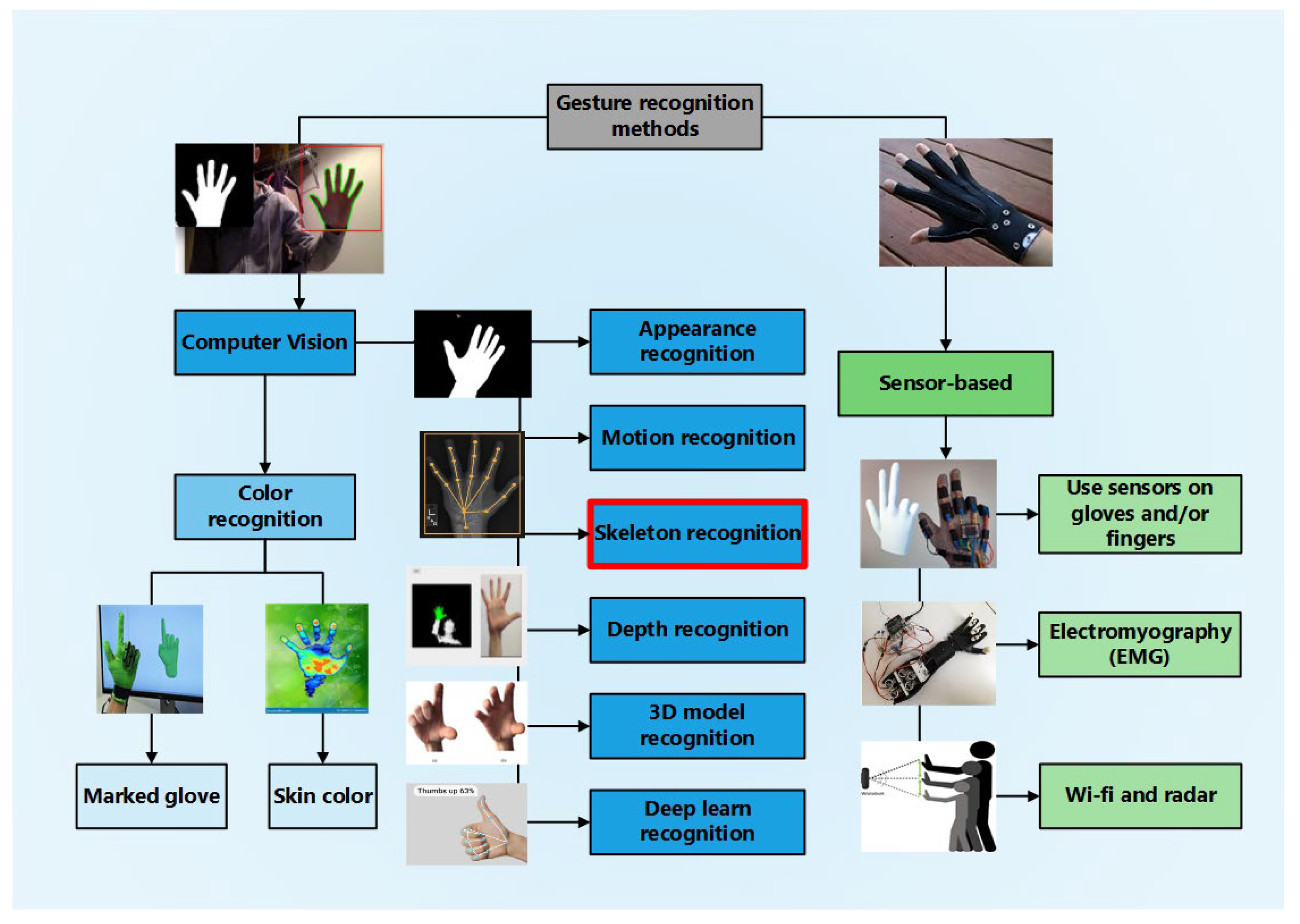
These are just some of the advances that have improved the ability to recognize human gestures accurately and quickly, providing real-time feedback to users in an HCI [41,42]. Qi et al., in 2023, in a taxonomy review, proposed to cover the study methods used for hand gesture and hand movement recognition [43]. This is shown below in Figure 1.
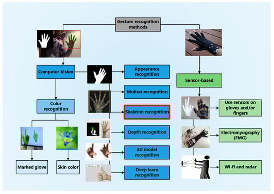
Figure 1.
Taxonomy of hand gesture recognition.
Figure 1 shows the main sign recognition methods: vision by computer, which is derived from those based on gloves and color segmentation, and those based on sensors, which are the sensors in gloves, EMG, Wi-Fi, and radar.
3. Materials and Methods
3.1. Software and Hardware Characteristics
For this work, a CPU with an AMD Ryzen 5 5600G processor (AMD, Santa Clara, CA, USA) and Radeon graphics at 3.90 GHz and 16 GB of RAM and a Logitech Model C920 HD Pro 1080p 960-000764 webcam (Logitech, Lausanne, Switzerland) were used. An Arduino Uno, a board based on an Atmega328 microcontroller, was also used. It has 14 digital input/output pins (4 of which can be used for PWM outputs), 6 analog inputs, a 16 MHz ceramic resonator, a female USB connector, a power jack, an ICSP connector, and a reset button. A PCA9685 Servo Controller Module was used, which is designed for servo control. It also includes a terminal block for powering the servos, connectors for powering the logic part, and I2C pins to communicate with the board. The module was connected to the uHand UNO Open-Source AI Bionic Robot Hand Support Somatosensory Control, Arduino Programming, which has 6 DC-powered servomotors that can precisely control position (from 0° to 180°) or speed (in revolutions per minute, rpm, in clockwise or counterclockwise directions). They have three pins for connection: power (5 V, typically), ground (GND), and the signal pin. Through the latter, the control system sends the PWM signal to the servomotor to indicate the position or speed it should reach, depending on the type of servomotor used. The model was built using the MediaPipe classifier (0.10.21.) as a descriptor of the hand skeleton, OpenCV (4.8.1) to measure the internal angles of the hand, and the Python sklearn library (version 9.11.9) [44,45]. Finally, we performed with four individuals: two adults (male and female) and two young people (male). To prove that regardless of being male or female, young or adult, the method proved reliable because it is governed by hand movement based on angles independent of the distance and/or position concerning the camera.
3.2. Implementation of a Gesture Recognition System for Robotic Hand Control
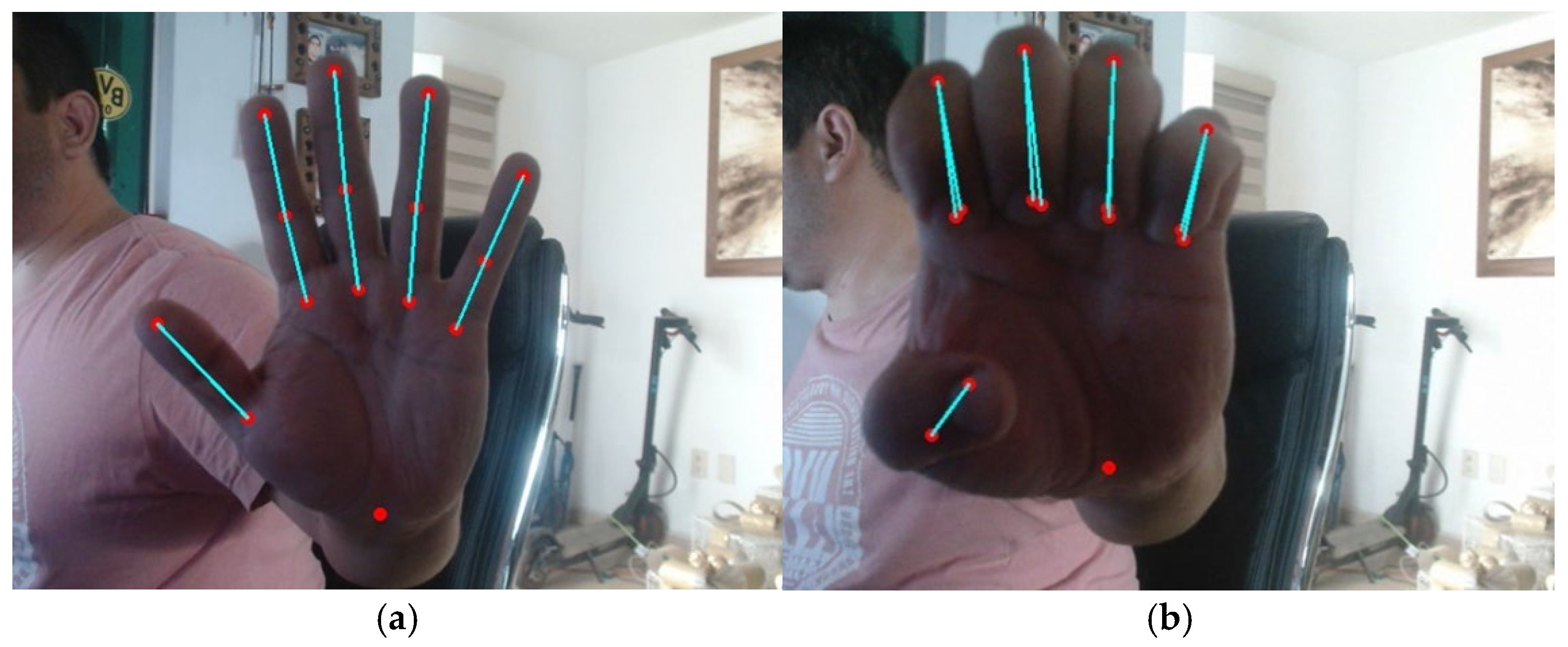
The proposed project aims to implement a hand gesture and movement recognition system based on computer vision in communication with a robotic hand, which can replicate the detected gestures through image processing. The system detects and recognizes the user’s movements, sending the corresponding commands to the robotic hand to reproduce the identified gesture, basic movements such as opening and closing the fingers, and other more complex movement patterns. A webcam connected to the system was used for video capture, and a 78-degree monocular camera was used for gesture recognition. The video setup was configured with a frame rate of approx. 24 p/s to ensure smooth and real-time detection; hand detection was carried out using the MediaPipe hand detection model. This model allows for identifying and tracking landmarks on the hand, including the phalanges of the fingers and wrist. The model’s configuration was tuned to maximize detection accuracy while maintaining a balance with processing speed. As the video is captured, frames are processed to extract the coordinates of the hand landmarks in real time. The positions of the finger phalanges and wrist are recorded in pixels, normalized to the size of the captured frame. The extracted landmarks were visualized in real time on the captured video). Superimposing colored circles achieved this at the corresponding locations in the frame. In addition, the positions of the landmarks were plotted, allowing a clear visual interpretation of the hand movements, as shown in. Figure 2.
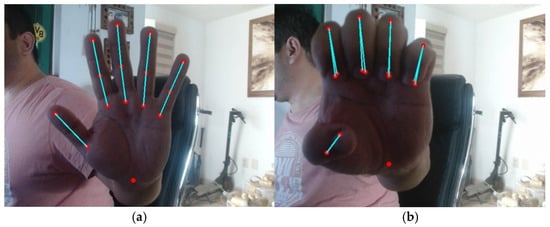
Figure 2.
Reference points were obtained using MediaPipe (a) with fingers extended with servo bias at 180 degrees and (b) with fingers contracted with servo bias at 0 degrees. The point is that this only refers to the wrist alone.
Hand movement data were sent through a serial port for communication with other systems. A serial connection was established at 115,200 baud, ensuring efficient, real-time transmission of the recorded data to complement the data capture. The process was run continuously, allowing the constant capture and visualization of hand movements. Adequate pauses were implemented to ensure system stability and prevent data overflow in the transmission. This comprehensive approach enables the robotic hand to replicate the movements detected in real-time accurately. Signal smoothing and dimensionality reduction techniques guarantee a robust system capable of adapting to different capture conditions and variations in the user’s movements while maintaining accuracy in the reproduction of gestures. The system design is based on integrating hardware and software components, and its workflow is presented in the system block diagram in Figure 3.
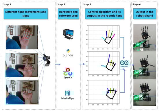
Figure 3.
Schematic illustration of the integration of hardware and software components for system implementation.
Motion and gesture recognition approaches follow the next key stages: data acquisition, gesture detection and segmentation, feature extraction, and classification. The schematic illustrates the operation of the gesture recognition system for the control of a robotic hand. On the left side, different hand movements and gestures are depicted, which are captured by a webcam. This camera sends the images to a system that uses Python, OpenCV, and MediaPipe to process visual signals. In the center of the schematic, the software is shown to identify and track hand landmarks, generating plots that represent the position of the fingers in real-time. These graphs are displayed as outputs in coordinates, where each movement is mapped in space. On the right side, it is indicated that the processed data are sent to the controller, which executes a control algorithm that translates the gesture information into commands for the motors of the robotic hand, allowing it to replicate the detected movements. This creates a real-time interaction between the user and the robotic hand. This flow includes the following stages:
3.2.1. Projection Geometry in Digital Camera (Stage 1)
The pinhole camera model is essential in computer vision as it describes the projection of a three-dimensional object onto a two-dimensional plane (image). This idealized model assumes a camera where light passes through a small hole, forming an inverted image on the sensor or film. The pinhole model describes the mathematical relationship of projecting points in 3D space onto an image plane. Let the center of projection be the origin of a Euclidean coordinate system and the Z-plane, which is called the image plane or focal plane. The center of projection mapping from 3D world space to 2D image coordinates using a human hand is shown in Figure 4.
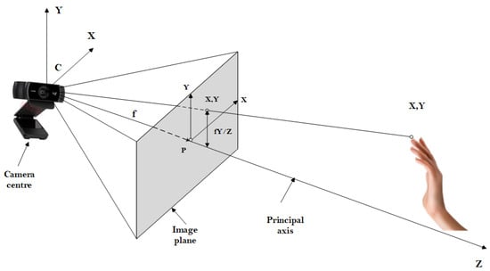
Figure 4.
Picture from Multiple View Geometry in Computer Vision.
The figure above shows the center of camera C, the hole in the camera, called the “optical center” or “pinhole”. It is a point through which all incoming light passes. The image plane: This is the plane where the image of the scene is projected. It is located at a distance known as the focal length f from the camera’s center. A 3D object is a point in real space with coordinates P = (X, Y, Z). The projection of a point in 3D onto the image plane in 2D coordinates is given by the following equations:
where:
X, Y, Z are the coordinates of the point in 3D space with respect to the camera reference system. Under the pinhole camera model, a point in space with coordinates is assigned to the point in the image plane . Ignoring the final image coordinate, x, y are the coordinates projected onto the image plane.
f is the focal length, the distance between the pinhole and the image plane.
The line from the center of the camera perpendicular to the image plane is called the principal axis. The point where the principal axis meets the image plane is called the principal point P. The camera’s center is located here at the origin of the coordinates. Assuming that the world and image points are represented in homogeneous coordinates, then the central projection can be expressed simply as a linear mapping between their homogeneous coordinates in terms of matrix multiplication, and this can also be expressed in terms of linear algebra using the projection matrix [46]. If we represent a point in the 3D space in homogeneous coordinates , the projection in 2D.
Is given by:
In this way, the pinhole camera takes a 3D point in space and transforms it into a 2D point in the image.
Because farther objects are at higher Z, they are projected closer to the center of the image. This explains why closer objects appear more prominent and farther objects appear smaller: it is the effect of perspective. This ideal model does not consider real optical effects such as lens distortion, which can occur in cameras with complex lenses. However, the pinhole model is a helpful starting point for this and many other applications [47].
3.2.2. Hand Reference Point Model (Stage 2)
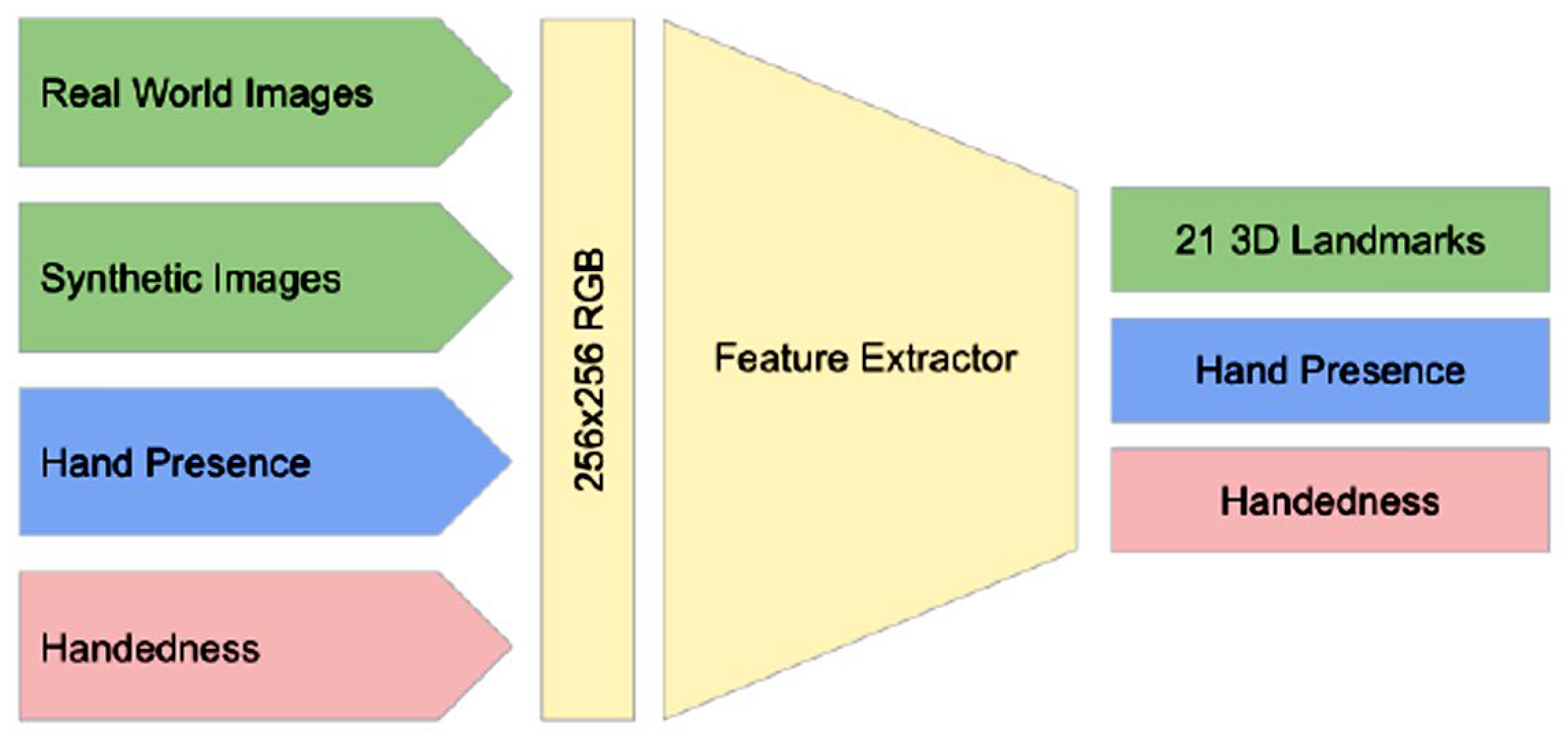
In our research, we used MediaPipe to implement a hand-tracking solution composed of a machine-learning model that operates as a landmark model of the hand working over the trimmed area, returning 2.5D landmarks with high accuracy, as seen in Figure 5.
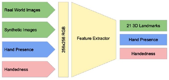
Figure 5.
The architecture of the hand-landmark model.
The landmark model allows the network to focus on improving the accuracy of landmark locations. In real-time tracking situations, the location of the hand in the current frame is derived from the prediction of the previous frame, thus avoiding running the detector on every frame. The detector is activated only at the first frame or when the prediction indicates that the hand has been missing to identify the initial positions of the hands. A one-shot detection model was implemented; this task is complex due to the variety of hand sizes and the need to detect hands that may be occluded. They propose a marker scheme since hands lack distinctive visual characteristics like those found on faces [12,13].
This model has been used to represent 15 points out of a possible 21, which helps to reduce dimensionality. The model can handle even partially visible hands and occlusions through learning that combines real-world images and synthetic datasets. To improve recovery from tracking failures, the model generates an additional output that estimates the probability that a hand is present in the provided cutout. If this probability is low, the detector is reactivated to re-establish tracking. The performance of the hand landmark models in controlling the activation of the hand motion detection model is a testament to the efficiency of the MediaPipe architecture. This system employs advanced synchronization techniques that enable seamless communication between ML components, resulting in high throughput and optimal performance, enabling real-time applications with minimal latency. This is especially important in applications involving hand-tracking recognition, where fast and accurate detection is crucial to performing the mathematical calculations needed to determine the angles that will be part of motor control. See Figure 2.
3.2.3. Transformation of Reference Points to Engine Control Angles (Stage 3)
We briefly describe how to convert the hand motions captured by computer vision into commands to control a robot hand. First, find the Normalized Position: Each point has x, y (and optionally z) coordinates normalized to the image frame. To convert these coordinates to absolute values:
Then, distances between points and angles are calculated, allowing specific gestures and movements to be identified. Finding the spatial relationship between points: The hierarchy between the key points will enable us to identify distances between points, which helps determine relative positions, such as finger openings.
These distances are mapped to vectors to determine the angles for the servos, defining positions from a bent to a fully extended finger. Resulting in angles formed by vectors. We use the dot product formula:
where , are vectors, and ∥∥ y ∥∥ are the Euclidean norms of these vectors. For example, the angle of the index finger can be calculated using the points at the base, the interphalangeal joint, and the tip of the index finger. The transformation from motion to control involves converting the coordinates and spatial relationships of the distal phalanges, joints, and finger bases to specific commands to control the servos of the robotic arm.
where:
: The actual distance between the base point and fingertip, measured in spatial coordinates.
0: The minimum expected value of the distance between the base point and the fingertip corresponds to the position where the finger is completely bent.
: The maximum value of the distance between the base point and fingertip that occurs when the finger is fully extended.
: The minimum servo angle, corresponding to the position where the finger is bent.
: The maximum servo angle, corresponding to the position where the finger is extended.
The finger movement control is given by the distance between the tip and base of the index finger and is mapped to a value between (0) Finger fully bent and (1) Finger fully extended. It is translated to an angle for the corresponding finger servo, and this angle is transformed into the Pulse Width Modulation (PWM) command [48]. For each servo, translate the desired angle θ to a pulse width command to be sent to the servo. This value is usually an integer representing the pulse duration in microseconds. PWM, which directly controls the servo position, is obtained from:
where:
θ: The desired angle in degrees, previously calculated by mapping (as explained in the previous formula).
m: It is the slope of the linear relationship between angle θ and the pulse width (PWM). It defines how much the pulse width changes per degree of angle.
b: It is the y-intercept representing the value of PWM when θ = 0.
3.2.4. Brief Description of the Hand Joints (Stage 4)
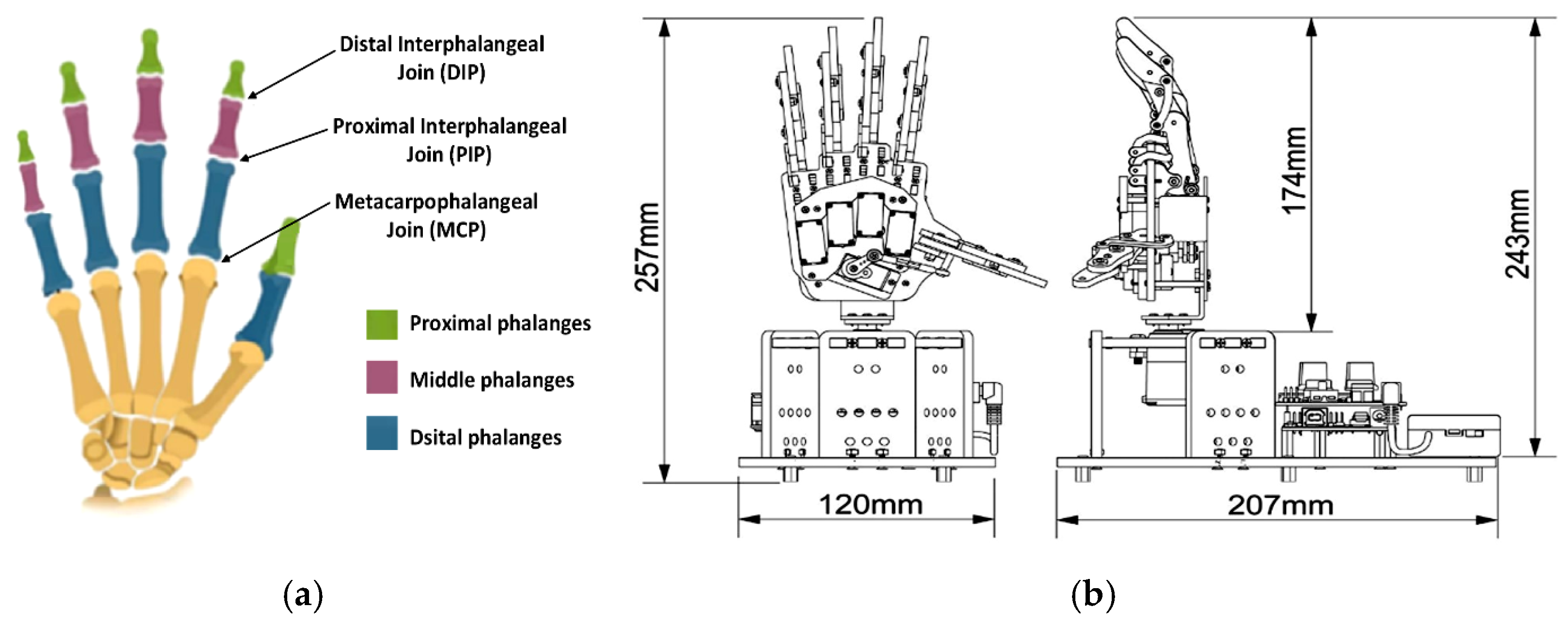
The human hand comprises five fingers: the thumb and the index, middle, ring, and little fingers. Each of these fingers, except for the thumb, consists of three bones: the distal phalanx (DP), intermediate phalanx (IP), and proximal phalanx (PP). The thumb, however, has only two: the distal phalanx and the proximal phalanx. The connections between these bones, known as joints, include the distal interphalangeal (DIP), proximal interphalangeal (PIP), and metacarpophalangeal (MCP) joints. There are approximately 27 joints in the hand, including the wrist joint, as shown in Figure 6a. These joints allow the hand to flex when the muscles contract. Each finger is controlled independently, allowing specific movements to be performed on the fingers of the robotic hand [49,50]. See Figure 6b.
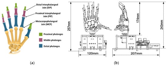
Figure 6.
Describes the hand: (a) hand skeleton with its phalanges and their respective connections; (b) Uhand-UNO robotic hand with its dimensions of the hand already armed. Cortesy by © 2025 Hiwonder. All Rights Reserved.
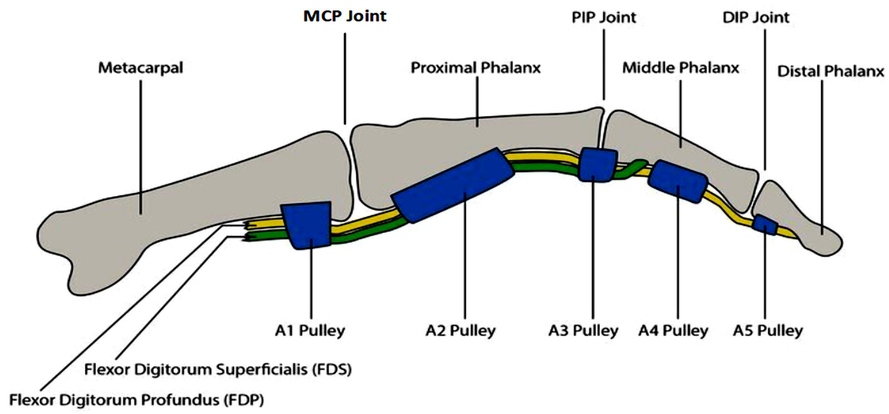
The muscles responsible for finger movements are divided into flexors and extensors. The flexor muscles are responsible for reducing the angle between the bones at the ends of the joints, while the extensor muscles increase this angle, generating an extension movement. The coordinated contraction of the flexor and extensor muscles allows for a wide range of hand postures. See Figure 7.
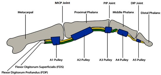
Figure 7.
Description of the index finger.
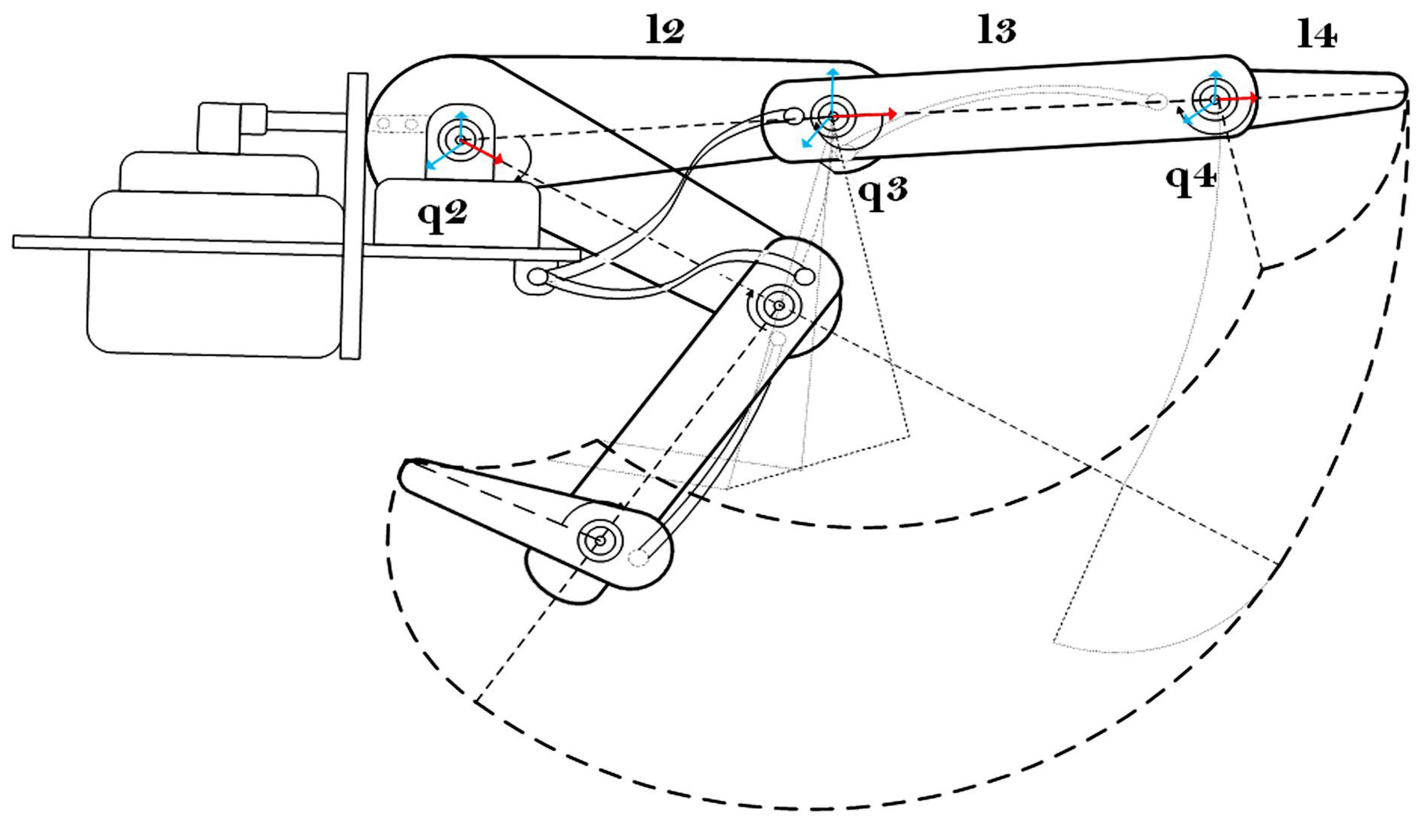
Its robotic counterpart controls movements by links and joints that emulate human phalanges and joints. For example, the L2 link in a robotic finger would be equivalent to the proximal phalanx in the human hand. At the same time, the MCP joint represents the rotation or pivot at the metacarpophalangeal (MCP) joint, referred to as q2 in robotic terms. Following this scheme, the PIP joint would be the analog of the proximal interphalangeal joint, controlled by q3, and the DIP joint, which corresponds to the distal interphalangeal joint, is controlled by q4. The illustration in Figure 8 shows how these movements are mechanically replicated in a robotic system, simulating a human finger’s joints and bone segments.
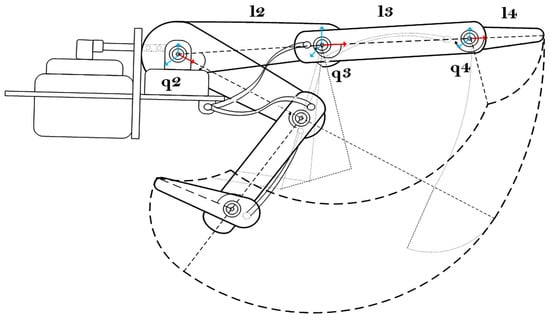
Figure 8.
Description of the index robot finger (Uhand UNO). L2, L3, L4 are the index finger links, q2, q2, q4 are the orthogonal turns of the index finger junctions.
The length of the bones in the fingers is a crucial factor in determining their size and structure. The kinematics of the robotic hand used are referred to as the adult human hand, especially in terms of bone dimensions. Details on the lengths and turning ranges of the finger movement are presented. The index, middle, ring, and little fingers have similar bony lengths; their range of motion swing is shown in Table 1. These fingers are considered to have a comparable range of motion, which has been integrated into the motion calculation of the robotic hand [51,52].

Table 1.
The length and motion range of the finger bones.
The range of mobility of the robot’s index finger is measured, but it does not limit the control calculation for its handling. Although the maximum and minimum flexion and extension angles are not the same, they are very close to those obtained by Bain et al. [53]. These values depend on the finger’s anthropometric characteristics and the dexterity or ability of the individual to perform these movements.
4. Benchmark Experiments
The main goal is to accurately replicate the movements of the human index finger, which involves calculating joint angles and modeling the relationship between the various segments of the robotic finger. Although the anatomy of the human hand provides detailed static models, such as joint structure and tendon routing, this work focuses on integrating hand movements into a functional robotic control system. In particular, the process of controlling the index finger is described, given that the other fingers can move analogously, achieving efficient and precise control. It is necessary to consider the direct and inverse kinematics in addition to the differential model [54].
4.1. Forward Kinematics
The Denavit-Hartenberg (DH) method is mainly used for manipulator robots, although it can also be applied to inverse kinematics with some modifications [55]. In this context, the DH method allows us to determine the position and orientation of the robot end effector in three-dimensional space. A homogeneous matrix representing the transformations of each link is constructed by associating it with a solid reference system. Representing the relative translations and rotations between the various links is possible. The matrix i−1 Ai represents the relative position and orientation between the systems associated with four consecutive links of the robot. 0A3 = 0A1 1A2 2A3 3A4. Each homogeneous transformation matrix Ai is defined using the standard formula, as shown in Equation (12), where the functions and represent the sine and cosine functions, respectively.
Table 2 shows parameters DH and transformation matrices for the model of a robotic finger with three joints: MCP, PIP, and DIP.
Table 2.
DH for Robotic finger.
where:
L1, L2, and L3 are the phalangeal lengths.
are the angles between the z-axes of adjacent links.
are the distances between the z-axes of adjacent links.
is the displacement along the z-axis for each link.
are joint angles in radians.
Transformation matrixes for each link are calculated using the following DH.
For the Jacobian matrix of a robotic arm with four degrees of freedom, we start from the x, y, and z positions of the end effector as a function of the joint variables , , and and calculate the partial derivatives needed to construct the Jacobian matrix.
4.2. Inverse Kinematic
The inverse kinematics of the robotic finger model are focused on finding the values of the angles θ1, θ2, θ3, and θ4 to position the end effector in a specific location (x, y, z). Inverse kinematics generally involve solving a system of nonlinear equations [56].
Solve θ1, from Equations (18) and (19):
θ1 = arctan(y/x)
Now, we have to calculate the projected distance r and the relative vertical displacement; we define r as the projected distance in the horizontal plane (XY):
At the level of r, z, θ2 defines the angle of elevation from the axis of the first link. We use the cosine theorem to calculate it. First, we define D, the total distance from the base to the end effector:
We then apply the cosine theorem to compute θ2:
The angle θ3, controls the contribution of the third link to the motion, but now considering the links L2, L3, and the end-effector projection. The calculation is similar to θ2, but we use the ratios of the segments to calculate the relative angle θ3:
The angle θ4 is the angle that allows the end effector to reach the desired orientation. It is calculated as the difference between the total desired angle θtotal = and the sum of θ2 + θ3:
4.3. Differential Model
The differential model (Jacobian matrix) tries to obtain the relationships between the velocities of the movement of the joints and the velocities of the robot end [57]. Now, we organize all the derivatives of x, y, and z in the Jacobian matrix J, with the columns corresponding to each of the articulations , , , and :
This is the Jacobian matrix for the robot (index finger) with four joints, which describes how the joints’ velocities affect the end-effector’s linear velocity in the following directions: , and .
With these reference experiments, we proceed to perform the experiments of the proposed model of the telematic robot hand.
5. Experimental Results
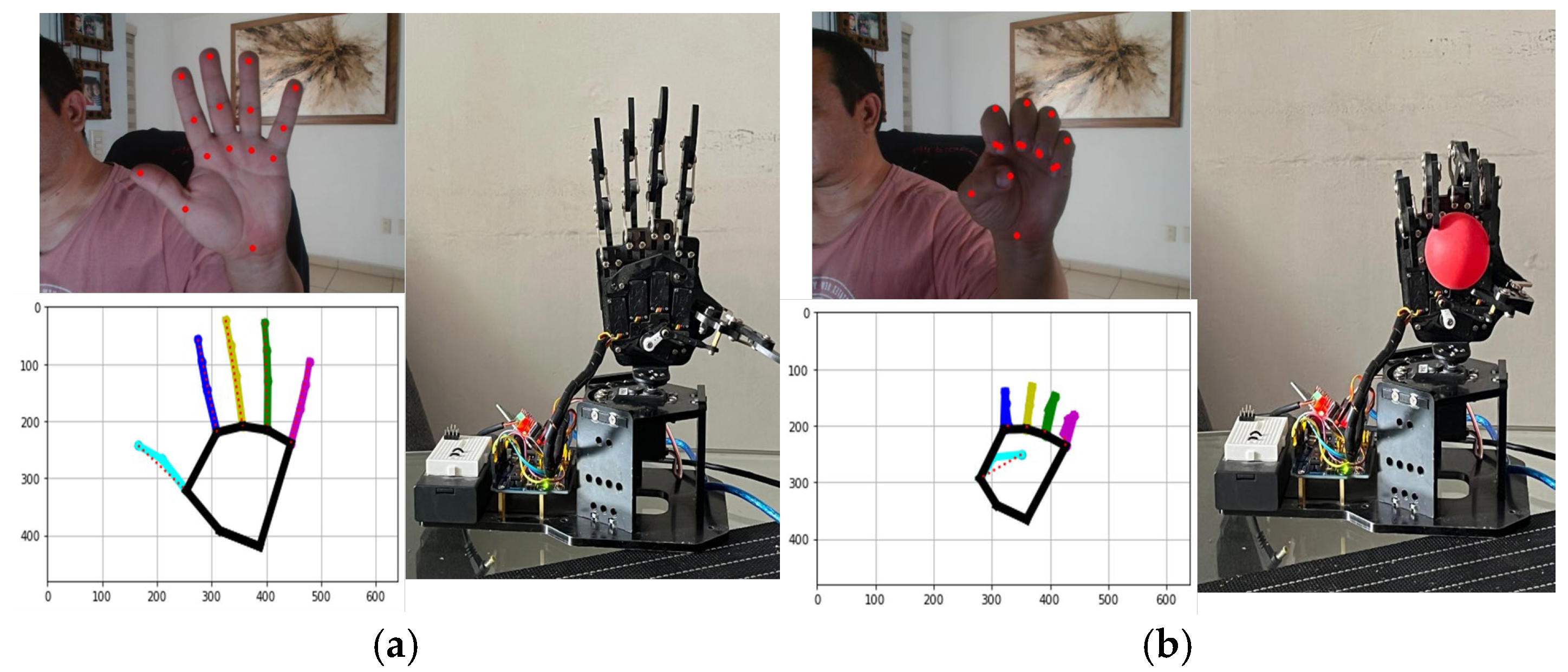
The proposed vision-based robot hand control system was evaluated through benchmark experiments to observe its accuracy in reproducing human hand movements; two adult hands (male and female) and two adolescent hands (male) were used. During real-time operation, the experiments focused on measuring the angular positions of the robotic finger joints (thumb, index, middle, ring, pinky, and wrist) and comparing them to truth values based on human motions. See Figure 9a,b.
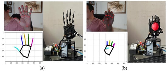
Figure 9.
(a) The experiment with the open hand command is observed. (b) The closed-hand command is observed holding a part checking the telematics action.
5.1. Real-Time Motion Replication
The Kalman filter is used in this experiment to soften the signal of measured angles and reduce the impact of noise on measurements. This allows more stable and accurate estimates of hand movements, which is crucial for the robotic hand control system to accurately replicate detected gestures. In short, it improves the robustness and accuracy of the system by providing filtered values that more consistently reflect actual motion, avoiding abrupt fluctuations that could affect engine performance or signal interpretation.
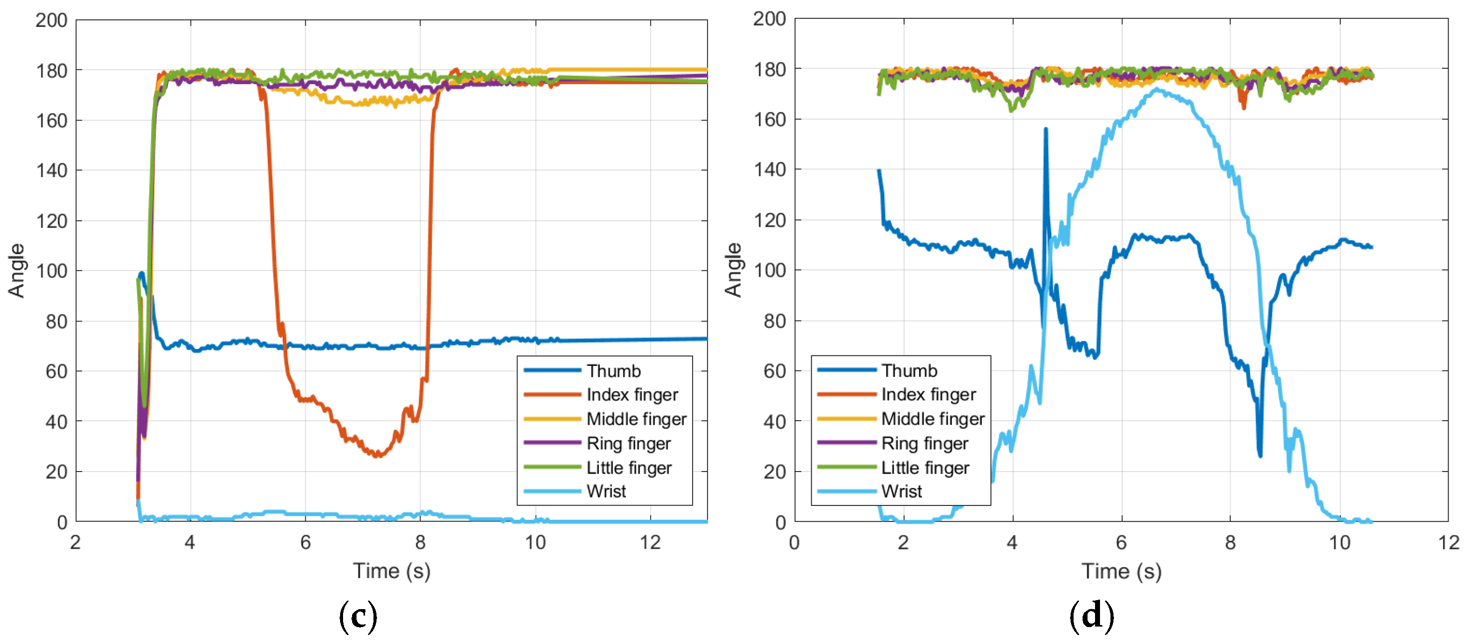
Figure 10a–d illustrate the angular trajectories of the robotic hand joints over time during four different gestures: full extension of the fingers, partial flexion of all, flexion of the index finger, and wrist rotation. The results demonstrate a close alignment between the movements of the human operator (input) and the responses of the robotic hand (output). For example, the index finger achieved a root mean square error (RMSE) of 9.31°. See Table 3, indicating high tracking accuracy. The wrist joint, critical to avoid occlusion in 180-degree rotations, which is the most significant contribution of this research since only a single sensor (camera) is used to achieve it, showed the lowest RMSE error was 4.9°, validating the effectiveness of the orthonormal design. Graphs 10.a and 10.b would be the motion versus time plots of Figure 9a,b.
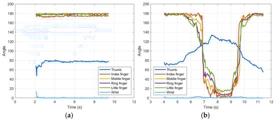
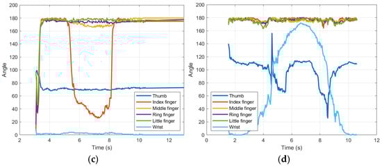
Figure 10.
Shows hand movements. (a) Extended fingers; (b) bent fingers; (c) finger flexion index; (d) wrist rotation.
Table 3.
Precision metrics.
5.2. Performance Metrics
Error metrics are quantitative measures used to evaluate the performance of a predictive model by comparing its predictions with actual values. These metrics indicate how accurate or incorrect a model is in regression, classification, or other machine-learning tasks; a quantitative analysis was conducted using the following metrics in Table 3:
- Mean Squared Error (MSE): Measures the average squared difference between predicted and actual joint angles.
- Root Mean Squared Error (RMSE): Represents the standard deviation of prediction errors.
- Mean Absolute Error (MAE): Average absolute difference between predicted and actual angles.
- Mean Absolute Percentage Error (MAPE): Relative error expressed as a percentage.
As shown in Table 3, the system achieved an overall MAE of 3.62° for the index finger and 2.9° for the wrist. The little finger had more significant errors (MAE = 4.13°), probably due to its shorter phalanges and limited visibility in certain gestures. In particular, the MAPE for the thumb (4.4%) and wrist (not applicable due to low reference angles) highlights the system’s robustness in reproducing fine movements.
5.3. Analysis of Angular Displacement Graphs (Human Fingers vs. Robotic)
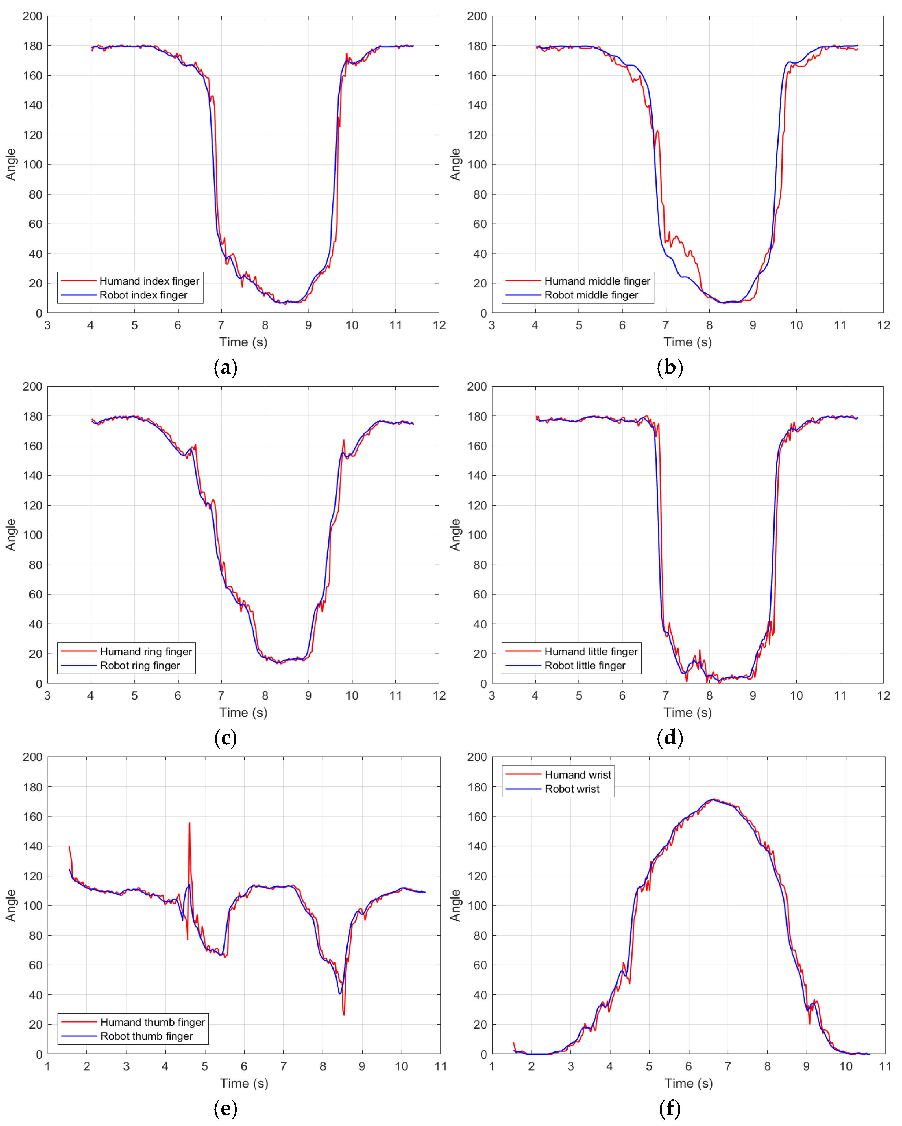
In Figure 11a–f. We have six graphs comparing the bending/extension angles of human and robotic fingers (thumb, index, middle, ring, pinkie, and wrist) over time, followed by graphs comparing the movements of the human hand versus the robot hand.
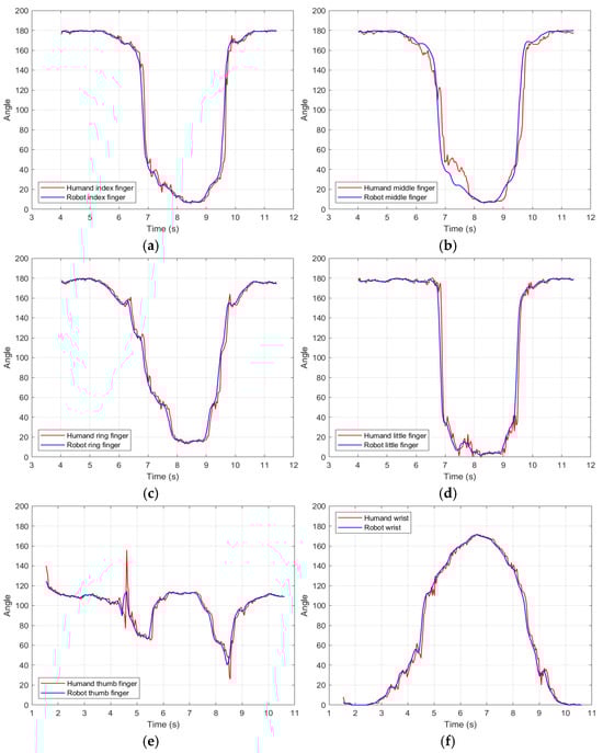
Figure 11.
(a) Index finger comparison. (b) Middle finger comparison. (c) Ring finger comparison. (d) It is a bit of a finger comparison. (e) Thumb-finger comparison. (f) Wrist comparison.
The analysis is detailed:
Thumb: Accuracy: High synchronization in the opening phase, but slight bending delay (~0.2 s). Error: MAE = 3.3°, MAPE = 4.4% (lowest), indicating good adaptation to complex thumb movements.
Index finger: Near-perfect match in real time during fast extensions. Error: MSE = 86.7, RMSE = 9.31°, possibly due to noise in detecting interphalangeal joints.
Middle finger: The smooth movement on the robot, but with slight oscillations (~5°) in intermediate positions. Error: MAE = 3.56°, suggesting an efficient mapping of the PIP and DIP angles.
Ring finger: Greater discrepancy (MSE = 138.6, RMSE = 11.7°), especially in deep flexions. Mechanical limitations in the replication of the MCP joint (30° maximum vs. 78° human).
Little finger: There were significant errors (MAPE not reported), possibly due to the shorter length of the robotic finger (20 mm vs. 23 mm human).
Wrist performance: Excellent accuracy (MAE = 2.9°) thanks to the orthonormal design that avoids occlusion in 180° turns.
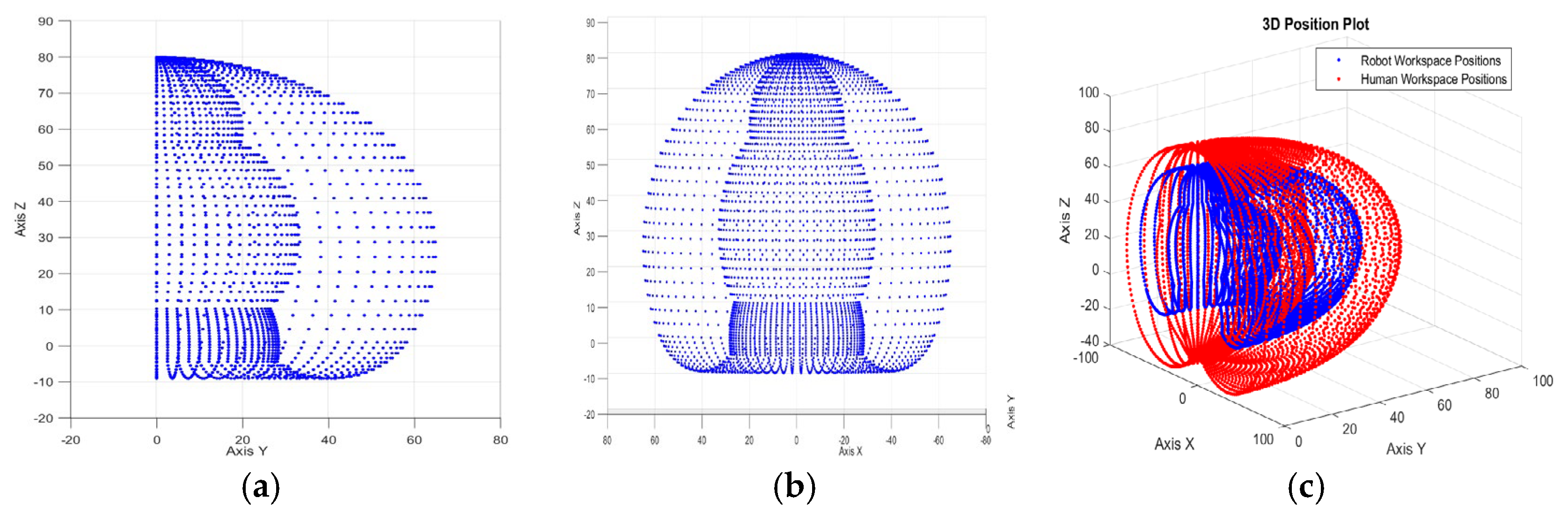
Figure 12a–c below shows how the index finger of the side- and front-view robot moves in its 3D workspace. Figure 12c shows the index finger of the robotic version in blue versus that of the human version in red. Quantitative and qualitative experimental results that support the effectiveness of the computer vision-based control system are presented. It is noteworthy that Figure 12, matches the workspace in Figure 8.
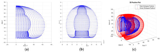
Figure 12.
(a) Lateral face of robot hand index finger workspace; (b) The front face of robot hand index finger workspace; (c) Comparison in the workspace of the human finger vs. the robot finger.
6. Discussion
In this work, the robotic hand replicated human gestures with less than 5% error for the primary joints (index, thumb, middle, and wrist). Also, the orthogonal wrist design eliminated occlusion problems, achieving an RMSE of less than 5° for 180° rotations. Our system achieved 94.2% gesture replication accuracy for key tasks such as grasping and wrist turning, outperforming traditional sensor-based methods like Yu et al. In 2024, they reached a 96.43% accuracy but required wearable sensors and gloves [20]. The vision-based approach reduced costs by 60% compared to glove-sensor systems while maintaining an accuracy of over 94%. Another advantage of this work is that a single 2D camera and MediaPipe reduced hardware complexity while maintaining competitive performance against multiple camera or depth sensor configurations (e.g., Albonico et al., 2023) [36].
However, the DH model and inverse kinematics calculations were validated by comparing theoretical joint angles (Equations (18)–(20)) with empirical servomotor outputs. For the index finger, the mean deviation between predicted and observed angles was 2.8 degrees, confirming the accuracy of the kinematic model. The Jacobian matrix (Equation (27)) also allowed smooth velocity control, minimizing jerky movements during dynamic tasks. High fidelity in the index finger, thumb, middle finger, and wrist, a low overall delay of less than 0.3 s, and suitability for real-time applications are highlighted. However, the discrepancies in lateral fingers reflect the need to calibrate the inverse kinematic model for mechanically constrained joints. One of the leading mechanical constraints in lateral fingers (ring, little finger) is due to the low dependence of these fingers on a human hand. The sensitivity to noise in interphalangeal joint detection and the direct reliance on light could have affected our work; therefore, in extended work, optimizing the DH model for fingers with reduced ranges of motion, incorporating Kalman filters to smooth oscillations in angle signals, and adjusting anthropometric lengths in the robotic design (e.g., pinky) could improve the current performance obtained.
7. Conclusions
This work demonstrated that a computer vision-based robotic control system can accurately replicate human hand movements, overcoming the limitations of traditional systems that rely on wearable sensors. The combination of MediaPipe and a 2D camera approach provides an accessible and effective method for controlling robotic hands, opening up new opportunities in teleoperation, rehabilitation, and personal assistance applications. As limitations in detecting lateral fingers are addressed and control algorithms are optimized, this system could significantly contribute to developing prosthetics and robotic devices that improve the quality of life for individuals. Future research will focus on integrating ML techniques to enhance the system’s adaptability and accuracy in dynamic environments.
The comparison between the movements of a robot’s index finger and a human’s is fascinating and crucial for developing advanced robotics. The ability of a robot to mimic human movements can improve its efficiency in everyday tasks and work environments where precise manipulation is essential. Furthermore, these studies can contribute to the design of more functional and ergonomic prostheses and extensions that replicate the dynamics and functionality of the human hand. Research in this area advances technology in fields such as industry and medicine and significantly impacts the quality of life for people who need to work with extensions of their body, whether remotely or telematically.
Supplementary Materials
The following supporting information can be downloaded at https://github.com/gggvamp/robothand/blob/main/Video%20de%20WhatsApp%202024-09-26%20a%20las%2020.41.12_5dcedfa7.mp4 (accessed on 12 March 2025), video. https://github.com/gggvamp/robothand/blob/main/zjp-dwjj-edi%20(2025-01-26%2020_00%20GMT-6).mp4 (accessed on 12 March 2025), video. https://github.com/gggvamp/robothand/blob/main/manoangulo6ultimate.py (accessed on 12 March 2025), program.
Author Contributions
G.G.-G. conceptualized the work, edited the manuscript, and prepared. The experiments use computer visión algorithms. G.d.C.L.-A. conceptualized the work, wrote parts of the manuscript, provided additional analysis, and revised the manuscript. J.d.J.N.J. Supervised, wrote parts of the manuscript, provided additional analysis, and revised the manuscript. All authors have read and agreed to the published version of the manuscript.
Funding
Technical Industrial Teaching Center supported this research. The action program was under academic direction (research work PI-10-2024).
Institutional Review Board Statement
Not applicable.
Informed Consent Statement
Not applicable.
Data Availability Statement
This information has been detailed in the Supplementary Materials.
Conflicts of Interest
The authors declare no conflicts of interest.
References
- Singh, D.K. Recognizing hand gestures for human computer interaction. In Proceedings of the 2015 International Conference on Communications and Signal Processing (ICCSP), Melmaruvathur, India, 2–4 April 2015; pp. 0379–0382. [Google Scholar] [CrossRef]
- Sezgin, N. A new hand finger movements’ classification system based on bicoherence analysis of two-channel surface EMG signals. Neural Comput. Appl. 2019, 31, 3327–3337. [Google Scholar] [CrossRef]
- Avilés-Mendoza, K.; Gaibor-León, N.G.; Asanza, V.; Lorente-Leyva, L.L.; Peluffo-Ordóñez, D.H. A 3D Printed, Bionic Hand Powered by EMG Signals and Controlled by an Online Neural Network. Biomimetics 2023, 8, 255. [Google Scholar] [CrossRef] [PubMed]
- Wu, Y.; Liang, S.; Zhang, L.; Chai, Z.; Cao, C.; Wang, S. Gesture recognition method based on a single-channel sEMG envelope signal. J. Wirel. Commun. Netw. 2018, 2018, 35. [Google Scholar] [CrossRef]
- García-Gil, G.; López-Armas, G.d.C.; Sánchez-Escobar, J.J.; Salazar-Torres, B.A.; Rodríguez-Vázquez, A.N. Real-Time Machine Learning for Accurate Mexican Sign Language Identification: A Distal Phalanges Approach. Technologies 2024, 12, 152. [Google Scholar] [CrossRef]
- Wameed, M.; Alkamachi, A.M. Hand Gestures Robotic Control Based on Computer Vision. Int. J. Intell. Syst. Appl. Eng. 2023, 11, 1013. [Google Scholar]
- Wang, Y.; Zhang, W. Data glove control of robot hand with force telepresence. In Proceedings of the 2015 IEEE International Conference on Robotics and Biomimetics (ROBIO), Zhuhai, China, 6–9 December 2015; pp. 314–319. [Google Scholar] [CrossRef]
- Kawasaki, H.; Mouri, T. Humanoid Robot Hand and its Applied Research. J. Robot. Mechatron. 2019, 31, 16–26. [Google Scholar] [CrossRef]
- Cai, C.; Somani, N.; Knoll, A. Orthogonal Image Features for Visual Servoing of a 6-DOF Manipulator with Uncalibrated Stereo Cameras. IEEE Trans. Robot. 2016, 32, 452–461. [Google Scholar] [CrossRef]
- Chen, Q.G.; Wan, L.; Pan, P.R.Y.J.; Chang, Y.K. Real-Time Vision-based Control of 7-DOF Robotic Manipulator for Pick-and-Place Tasks in Grasping Fruit. In Proceedings of the 2022 CSME International Congress of Canadian Mechanical Engineering, Edmonton, AB, Canada, 5–8 June 2022. [Google Scholar]
- Mohammadi Amin, F.; Rezayati, M.; van de Venn, H.W.; Karimpour, H. A Mixed-Perception Approach for Safe Human–Robot Collaboration in Industrial Automation. Sensors 2020, 20, 6347. [Google Scholar] [CrossRef]
- Lugaresi, C.; Tang, J.; Nash, H.; McClanahan, C.; Uboweja, E.; Hays, M.; Zhang, F.; Chang, C.-L.; Yong, M.G.; Lee, J.; et al. MediaPipe: A Framework for Building Perception Pipelines. arXiv 2019, arXiv:1906.08172. [Google Scholar]
- Zhang, F.; Bazarevsky, V.; Vakunov, A.; Tkachenka, A.; Sung, G.; Chang, C.-L.; Grundmann, M. MediaPipe Hands: On-device Real-time Hand Tracking. arXiv 2020, arXiv:2006.10214. [Google Scholar]
- Oqua, O.I.; Chen, J.; Annamalai, A.; Yang, C. 3D Printed Data Glove Design for VR Based Hand Gesture Recognition. In Proceedings of the 2018 11th International Workshop on Human Friendly Robotics (HFR), Shenzhen, China, 13–14 November 2018; pp. 66–71. [Google Scholar] [CrossRef]
- Zhang, B.; Suzuki, A.; Lim, H. Development of Sensitive Glove Type Wearable Robot System. In Proceedings of the 2019 IEEE Conference on Virtual Reality and 3D User Interfaces (VR), Osaka, Japan, 23–27 March 2019; pp. 1581–1582. [Google Scholar] [CrossRef]
- Nassour, J.; Amirabadi, H.G.; Weheabby, S.; Ali, A.A.; Lang, H.; Hamker, F. A Robust Data-Driven Soft Sensory Glove for Human Hand Motions Identification and Replication. IEEE Sens. J. 2020, 20, 12972–12979. [Google Scholar] [CrossRef]
- Filipowska, A.; Filipowski, W.; Raif, P.; Pieniążek, M.; Bodak, J.; Ferst, P.; Pilarski, K.; Sieciński, S.; Doniec, R.J.; Mieszczanin, J.; et al. Machine Learning-Based Gesture Recognition Glove: Design and Implementation. Sensors 2024, 24, 6157. [Google Scholar] [CrossRef] [PubMed] [PubMed Central]
- Tchantchane, R.; Zhou, H.; Zhang, S.; Alici, G. A Review of Hand Gesture Recognition Systems Based on Noninvasive Wearable Sensors. Adv. Intell. Syst. 2023, 5, 2300207. [Google Scholar] [CrossRef]
- Chiu, J.P.C.; Nichols, E. Named entity recognition with bidirectional LSTM-CNNs. Trans. Assoc. Comput. Linguist. 2016, 4, 357–370. [Google Scholar] [CrossRef]
- Yu, Z.; Lu, C.; Zhang, Y.; Jing, L. Gesture-Controlled Robotic Arm for Agricultural Harvesting Using a Data Glove with Bending Sensor and OptiTrack Systems. Micromachines 2024, 15, 918. [Google Scholar] [CrossRef] [PubMed]
- Liu, Q.; Ghodrat, S.; Huisman, G.; Jansen, K.M.B. Shape memory alloy actuators for haptic wearables: A review. Mater. Des. 2023, 233, 112264. [Google Scholar] [CrossRef]
- Seo, S.-W.; Jung, W.-S.; Kim, Y. 3D Hand Motion Generation for VR Interactions Using a Haptic Data Glove. Multimodal Technol. Interact. 2024, 8, 62. [Google Scholar] [CrossRef]
- Ridremont, T.; Singh, I.; Bruzek, B.; Erel, V.; Jamieson, A.; Gu, Y.; Merzouki, R.; Wijesundara, M.B.J. Soft Robotic Bilateral Rehabilitation System for Hand and Wrist Joints. Machines 2024, 12, 288. [Google Scholar] [CrossRef]
- Xu, Q.; Yang, D.; Li, M.; Ren, X.; Yuan, X.; Tang, L.; Wang, X.; Liu, S.; Yang, M.; Liu, Y.; et al. Design and Verification of Piano Playing Assisted Hand Exoskeleton Robot. Biomimetics 2024, 9, 385. [Google Scholar] [CrossRef]
- Medina-Coello, P.; Salvador-Dominguez, B.; Badesa, F.J.; Rodriguez Corral, J.M.; Plastrotmann, H.; Morgado-Estevez, A. Anthropomorphic Robotic Hand Prosthesis Developed for Children. Biomimetics 2024, 9, 401. [Google Scholar] [CrossRef]
- Li, X.; Jettanasen, C.; Chiradeja, P. Exploration of Sign Language Recognition Methods Based on Improved YOLOv5s. Computation 2025, 13, 59. [Google Scholar] [CrossRef]
- De Smedt, Q.; Wannous, H.; Vandeborre, J.-P. Skeleton-Based Dynamic Hand Gesture Recognition. In Proceedings of the 2016 IEEE Conference on Computer Vision and Pattern Recognition Workshops (CVPRW), Las Vegas, NV, USA, 26 June–1 July 2016; pp. 1206–1214. [Google Scholar] [CrossRef]
- Roy, A.; Chakraborty, S. Support vector machine in structural reliability analysis: A review. Reliab. Eng. Syst. Saf. 2023, 233, 109126. [Google Scholar] [CrossRef]
- Oudah, M.; Al-Naji, A.; Chahl, J. Hand Gesture Recognition Based on Computer Vision: A Review of Techniques. J. Imaging 2020, 6, 73. [Google Scholar] [CrossRef] [PubMed]
- Indolia, S.; Goswami, A.K.; Mishra, S.P.; Asopa, P. Conceptual Understanding of Convolutional Neural Network—A Deep Learning Approach. Procedia Comput. Sci. 2018, 132, 679–688. [Google Scholar] [CrossRef]
- Köpüklü, O.; Gunduz, A.; Kose, N.; Rigoll, G. Real-time Hand Gesture Detection and Classification Using Convolutional Neural Networks. In Proceedings of the 2019 14th IEEE International Conference on Automatic Face & Gesture Recognition (FG 2019), Lille, France, 14–18 May 2019; pp. 1–8. [Google Scholar]
- Ahad, M.T.; Li, Y.; Song, B.; Bhuiyan, T. Comparison of CNN-based deep learning architectures for rice diseases classification. Artif. Intell. Agric. 2023, 9, 22–35. [Google Scholar] [CrossRef]
- Dang, T.L.; Tran, S.D.; Nguyen, T.H.; Kim, S.; Monet, N. An improved hand gesture recognition system using keypoints and hand bounding boxes. Array 2022, 16, 100251. [Google Scholar] [CrossRef]
- Altayeb, M. Hand Gestures Replicating Robot Arm based on MediaPipe. Indones. J. Electr. Eng. Inform. (IJEEI) 2023, 11, 727–737. [Google Scholar] [CrossRef]
- Wameed, M.; Alkamachi, A.M.; Erçelebi, E. Tracked Robot Control with Hand Gesture Based on MediaPipe. Al-Khwarizmi Eng. J. 2023, 19, 56–71. [Google Scholar] [CrossRef]
- Albonico, M.; Đorđević, M.; Hamer, E.; Malavolta, I. Software engineering research on the Robot Operating System: A systematic mapping study. J. Syst. Softw. 2023, 197, 111574. [Google Scholar] [CrossRef]
- Chen, N.; Wan, L.; Chen, Q.; Pan, Y.-J. Real Time Vision-based Human Hand Motion Tracking and Grasping for a Robotic Manipulator with Soft Hand. In Proceedings of the Canadian Society for Mechanical Engineering International Congress 2023 Computational Fluid Dynamics Canada International Congress CSME—CFD-SC2023, Sherbrooke, QC, Canada, 28–31 May 2023. [Google Scholar] [CrossRef]
- Sluÿters, A.; Lambot, S.; Vanderdonckt, J.; Vatavu, R.-D. RadarSense: Accurate Recognition of Mid-air Hand Gestures with Radar Sensing and Few Training Examples. ACM Trans. Interact. Intell. Syst. 2023, 13, 16. [Google Scholar] [CrossRef]
- Phuong, L.H.; Cong, V.D. Control the Robot Arm through VisionBased Human Hand Tracking. FME Trans. 2024, 52, 37–44. [Google Scholar] [CrossRef]
- Olikkal, P.; Pei, D.; Karri, B.K.; Satyanarayana, A.; Kakoty, N.M.; Vinjamuri, R. Biomimetic learning of hand gestures in a humanoid robot. Front. Hum. Neurosci. 2024, 18, 1391531. [Google Scholar] [CrossRef]
- Nguyen, X.S.; Brun, L.; Lézoray, O.; Bougleux, S. Skeleton-Based Hand Gesture Recognition by Learning SPD Matrices with Neural Networks. In Proceedings of the 2019 14th IEEE International Conference on Automatic Face & Gesture Recognition (FG 2019), Lille, France, 14–18 May 2019; pp. 1–5. [Google Scholar] [CrossRef]
- Pyun, K.R.; Kwon, K.; Yoo, M.J.; Kim, K.K.; Gong, D.; Yeo, W.-H.; Han, S.; Ko, S.H. Machine-learned wearable sensors for real-time hand-motion recognition: Toward practical applications. Natl. Sci. Rev. 2024, 11, nwad298. [Google Scholar] [CrossRef] [PubMed]
- Qi, J.; Ma, L.; Cui, Z.; Yu, Y. Computer vision-based hand gesture recognition for human-robot interaction: A review. Complex. Intell. Syst. 2024, 10, 1581–1606. [Google Scholar] [CrossRef]
- Zelinsky, A. Learning OpenCV—Computer Vision with the OpenCV Library (Bradski, G.R. et al.; 2008) [On the Shelf]. IEEE Robot. Autom. Mag. 2009, 16, 100. [Google Scholar] [CrossRef]
- Pedregosa, F.; Varoquaux, G.; Gramfort, A.; Michel, V.; Thirion, B.; Grisel, O.; Blondel, M.; Prettenhofer, P.; Weiss, R.; Dubourg, V.; et al. Scikit-learn: Machine Learning in Python. Mach. Learn. Python 2011, 12, 2825–2830. [Google Scholar]
- Ponce, E.; Khrenov, B.; Panasyuk, M.I.; Martinez, O.; Salazar, H.; Garipov, G.; Klimov, P. Pinhole camera for study of atmospheric UV flashes as a source of background in the TUS experiment. Nucl. Instrum. Methods Phys. Res. Sect. A Accel. Spectrom. Detect. Assoc. Equip. 2011, 639, 77–78. [Google Scholar] [CrossRef]
- Hartley, R.; Zisserman, A. Multiple View Geometry in Computer Vision, 2nd ed.; Cambridge University Press: Cambridge, UK, 2004. [Google Scholar]
- Bakaoukas, A.G.; Triantafyllos, K. Pulse width modulation (PWM) method for power components estimation under harmonic distortion conditions. In Proceedings of the 2015 Science and Information Conference (SAI), London, UK, 28–30 July 2015; pp. 1132–1139. [Google Scholar] [CrossRef]
- Loren, G.J.; Shoemaker, S.D.; Burkholder, T.J.; Jacobson, M.D.; Fridén, J.; Lieber, R.L. Human wrist motors: Biomechanical design and application to tendon transfers. J. Biomech. 1996, 29, 331–342. [Google Scholar] [CrossRef]
- Deshpande, A.; Balasubramanian, R.; Lin, R.; Dellon, B.; Matsuoka, Y. Understanding variable moment arms for the index finger MCP joints through the ACT hand. In Proceedings of the 2nd IEEE RAS & EMBS International Conference on Biomedical Robotics and Biomechatronics, Scottsdale, Arizona, 19–22 October 2008; pp. 776–782. [Google Scholar]
- Velázquez-Sánchez, A.; Merchán-Cruz, E.; Hernández-Gómez, L.H.; Urriolagoitia-Calderón, G. Rango de movilidad y función descriptiva del dedo índice. Científica 2007, 11, 177–188. [Google Scholar]
- Abdul Wahit, M.A.; Ahmad, S.A.; Marhaban, M.H.; Wada, C.; Izhar, L.I. 3D Printed Robot Hand Structure Using Four-Bar Linkage Mechanism for Prosthetic Application. Sensors 2020, 20, 4174. [Google Scholar] [CrossRef]
- Bain, G.I.; Polites, N.; Higgs, B.G.; Heptinstall, R.J.; McGrath, A.M. The functional range of motion of the finger joints. J. Hand Surg. Eur. 2015, 40, 406–411. [Google Scholar] [CrossRef] [PubMed]
- Spong, M. Robot Modeling and Control, Second Edition [Bookshelf]. IEEE Control Syst. 2022, 42, 126–128. [Google Scholar] [CrossRef]
- Rocha, C.R.; Tonetto, C.P.; Dias, A. A comparison between the Denavit–Hartenberg and the screw-based methods used in kinematic modeling of robot manipulators. Robot. Comput.-Integr. Manuf. 2011, 27, 723–728. [Google Scholar] [CrossRef]
- Zhang, X.; Wang, H.; Rong, Y.; Niu, J.; Tian, J.; Li, S.; Ning, Y. Improved inverse kinematics and dynamics model research of general parallel mechanisms. J. Mech. Sci. Technol. 2023, 37, 943–954. [Google Scholar] [CrossRef]
- Ueda, K.; Katsura, S. Development of 4-DOF Tendon-driven Robot Finger. In Proceedings of the 2024 IEEE 18th International Conference on Advanced Motion Control (AMC), Kyoto, Japan, 28 February–1 March 2024; pp. 1–6. [Google Scholar] [CrossRef]


Disclaimer/Publisher’s Note: The statements, opinions and data contained in all publications are solely those of the individual author(s) and contributor(s) and not of MDPI and/or the editor(s). MDPI and/or the editor(s) disclaim responsibility for any injury to people or property resulting from any ideas, methods, instructions or products referred to in the content. |
© 2025 by the authors. Licensee MDPI, Basel, Switzerland. This article is an open access article distributed under the terms and conditions of the Creative Commons Attribution (CC BY) license (https://creativecommons.org/licenses/by/4.0/).