Article

Design and Measurement of a High-Efficiency W-Band Microstrip Antenna with Enhanced Matching for 6G Automotive Radar and ADAS Systems

by
Alaa M. Abada
1,
Anwer S. Abd El-Hameed
2,*,
Angie R. Eldamak
1 and
Hadia M. El-Hennawy
1
1
Electronics & Communications Engineering Department, Ain Shams University, Cairo 11517, Egypt
2
Electronics Research Institute, Cairo 12622, Egypt
*
Author to whom correspondence should be addressed.
Technologies 2025, 13(12), 555; https://doi.org/10.3390/technologies13120555
Submission received: 25 October 2025 / Revised: 19 November 2025 / Accepted: 25 November 2025 / Published: 27 November 2025

Abstract

A compact, single-layer W-band microstrip antenna for forward-looking ADAS radar in the 77–79 GHz band is presented. The 16.5 × 22 mm2 PCB element integrates a linear microstrip taper, two shorting vias, and a slot-loaded cavity to stabilize input reactance and broaden the in-band match. Full-wave simulations and launcher-based measurements using WR-12 TRL de-embedding and anechoic-chamber substitution confirm S11 ≤ −10 dB across 77–79 GHz. At 77/79 GHz, the antenna achieves end-fire realized gains of ≈9.9/≈11.2 dBi. The main beam is end-fire (peak near θ ≈ 90°), with −3 dB beamwidths of ≈36° in the θ-cut at φ = 0 (pointing ≈ 61°/56°) and ≈11.6° in the φ-cut at θ = 90°. First sidelobes are about −2.3/−2.5 dB (θ-cut) and −3.1/−3.4 dB (φ-cut). Cross-polarization is ≥18 dB below co-polarization, and the simulated radiation efficiency reaches ≈85% at 77 GHz and ≈80% at 79 GHz. A controlled thermal sweep (25–105 °C) yields < 100 MHz resonance drift while maintaining ≥ 10 dB return loss. Due to its planar architecture and clean feed integration, compact module packaging in short- to medium-range automotive radars.

1. Introduction

1.1. Background and Motivation

Advanced driver-assistance systems and emerging 6G/JCAS vehicular platforms require compact, manufacturable antennas around 77–79 GHz that deliver clean end-fire beams, suppressed sidelobes, and stable impedance under operational temperature swings. With the continuous advancement of automotive technologies, wireless communication systems have become essential for improving vehicle safety, efficiency, and overall user experience [1,2,3]. Among the most transformative innovations are Advanced Driver Assistance Systems (ADAS), which play a crucial role in reducing traffic accidents, an urgent concern, given that approximately 44,450 traffic-related fatalities were recently reported in the United States alone [4]. ADAS are reshaping modern transportation by integrating intelligent sensing and control technologies that enhance situational awareness and vehicle responsiveness [5].
As illustrated in Figure 1, radar-based sensing systems mounted on the vehicle body enable ADAS to detect and track surrounding objects, supporting critical functionalities such as automatic emergency braking, lane departure warning, and adaptive cruise control [6,7]. These capabilities are fundamental to enhancing road safety, particularly considering increasing regulatory mandates and consumer demand for advanced safety features. Moreover, the integration of ADAS with V2X communication networks further amplifies these benefits by enabling more accurate object detection and seamless V2X and V2I [7,8].
A key enabler of radar-based applications is the utilization of millimeter-wave frequency bands, particularly the W-band (75–110 GHz), defined by IEEE standards [9]. Within this spectrum, the 77–79 GHz range is especially important for short- and medium-range automotive radar. Microstrip antennas play a central role in achieving high-resolution detection due to their compact size, ease of integration, and high-frequency performance [10,11].
Ref. [12] proposed a compact dual-band mi-crostrip antenna operating at 24 GHz and 77 GHz for automotive radar and intelligent sensing of ADAS applications. While the design achieved high gain values exceeding 12 dBi in both bands, it suffered from potential inter-band interference, fabrication complexity, and a lack of validation under realistic automotive conditions. In [13], a magneto-electric dipole antenna array was developed specifically for 77 GHz radar applications. It demonstrated high gain (~16.5 dBi), narrow beamwidth, and excellent impedance matching. However, the multilayered structure increased fabrication difficulty and cost. Similarly, Ref. [14] introduced a dual-layer transmit-array antenna at 77 GHz with a peak gain of approximately 21 dBi and beam-steering capability of ±15°, providing improved angular resolution and ~75% radiation efficiency. Yet, the dual-layer configuration introduced significant alignment and fabrication challenges. Furthermore, Ref. [15] reported a 79 GHz wide-beam patch antenna and array for short-range radar, achieving a peak gain of 10.74 dBi. Its angular resolution, however, remained limited, and real-world performance validation was insufficient. In [16], a 77 GHz gap waveguide slot array was proposed, achieving a measured gain of 17.5 dBi with excellent polarization purity and isolation (>30 dB). Despite its high performance, the design required extremely precise fabrication, raising concerns about scalability for automotive mass production.
Although this work focuses on the regulated 77–79 GHz automotive band, numerous recent W-band (75–110 GHz) studies report planar, PCB-compatible antennas and packaging consistent with our approach [17]. Ref. [18] presents a single-layer PCB array with measured ≈14 dBi gain maintained across 100–110 GHz, validating low-cost planar implementations at the upper W-band, as well as a glass-substrate W-band microstrip array that mitigates dielectric and feed losses while sustaining >10 dBi over ~76–84 GHz. Also, Ref. [19] explains an LTCC/SIW W-band 4 × 4 array demonstrating high integration and high gain. Collectively, these findings support extending our element toward the higher end of 75–110 GHz.

1.2. Application Scope and Specifications

These prior works highlight the ongoing research efforts aimed at meeting the stringent requirements of modern ADAS [20,21]. 6G roadmaps target sub-THz/W-band JCAS/ISAC for high-resolution automotive sensing and short-range, high-capacity V2X links [22]. Antennas with clean end-fire beams, suppressed sidelobes, and easy arrayability are essential. The proposed single-layer PCB element at 77–79 GHz provides low mismatch and ≈−9 dB first-sidelobe levels, making it a practical tile for 6G-ready ADAS/JCAS arrays. However, challenges persist, particularly in balancing performance, integration feasibility, and fabrication complexity [23]. Table 1 compares the ADAS requirements in the 77–79 GHz band with the results obtained in this study. All mandatory specifications are satisfied, confirming the proposed antenna’s suitability for automotive radar. The table summarizes the target specifications, achieved values at 77 GHz and 79 GHz, and the corresponding figure references.
In this paper, we present the design, simulation, and fabrication of an ADAS antenna with a compact footprint of 22 × 16.5 mm2 (5.7 λ0 × 4.3 λ0). The antenna is specifically tailored for forward-looking automotive radar operating in the 77–79 GHz band (AEB/ACC/FCW). For completeness, wideband S-parameter and gain responses are reported across 75–110 GHz, while detailed radiation performance is evaluated at the critical band anchors, 77 and 79 GHz.

2. The Proposed ADAS Antenna Design

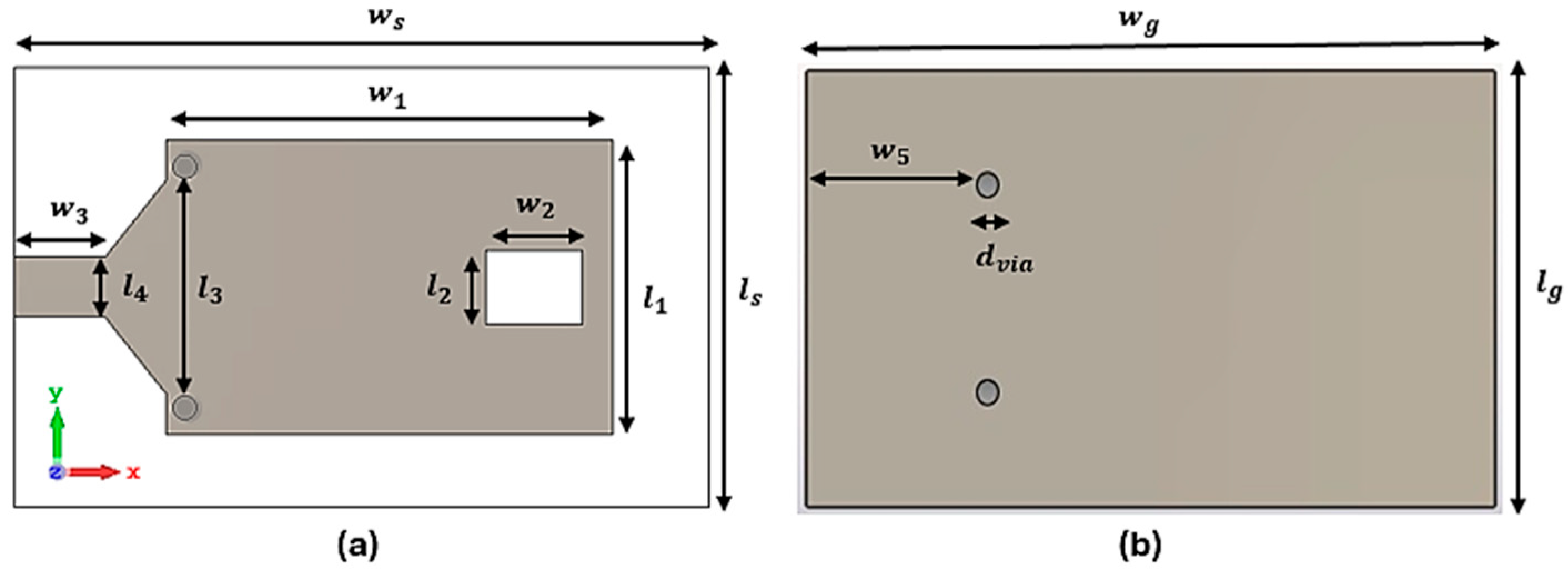
ADAS antennas play a critical role in multiple functions, including radar systems, Vehicle-to-Everything (V2X) communication, and navigation. Among microwave transmission lines, the microstrip line is one of the most widely used due to its compactness and ease of integration. The design process requires careful consideration of materials, antenna geometry, and placement within the vehicle to optimize performance and comply with regulatory standards [24]. In radar systems, ADAS antennas must operate at high frequencies, such as 77 GHz, to provide high-resolution data for object detection and collision avoidance. The proposed microstrip antenna (MSA) is implemented on Roger’s substrate with a dielectric constant ε r of 2.2, loss tangent (tan δ) of 0.0009, and a thickness of 0.762 mm. The antenna geometry was optimized through extensive simulations using CST Microwave Studio [25]. Figure 2 presents the top view and bottom view of the proposed design, while the optimum dimensions are summarized in Table 2.
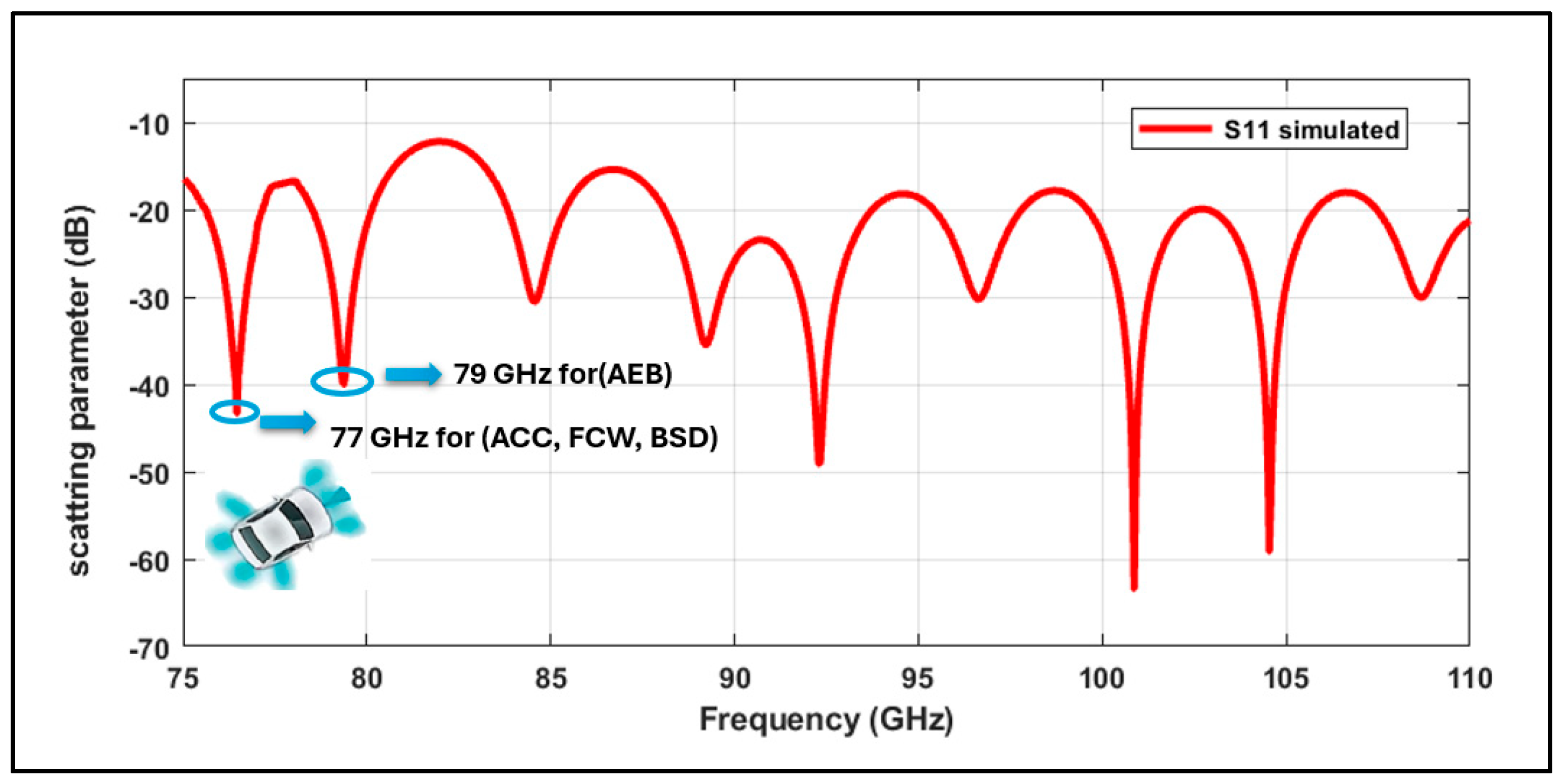
The antenna employs a rectangular patch precisely dimensioned to resonate at the target frequencies. It is fabricated on a substrate incorporating two shorting vias and is excited through a tapered transition. Figure 3 illustrates the simulated scattering parameters across 75–110 GHz, with particular emphasis on the 77–79 GHz band where S11 < −10 dB and excellent return loss (~−50 dB) is achieved at both 77 and 79 GHz, which is critical for ADAS applications. The antenna demonstrates multiple resonances, as indicated by the recurring dips in the S-parameter curve, confirming its ability to operate effectively at several frequencies. The 77–79 GHz response originates from coupled cavity-slot/patch interactions: the etched rectangular slot supports an approximately λg/2 resonance along its length, while the shorting vias introduce a λg/4 shunt return that tunes and slightly splits the fundamental mode, producing the two in-band minima

2.1. Tapered Transition Design

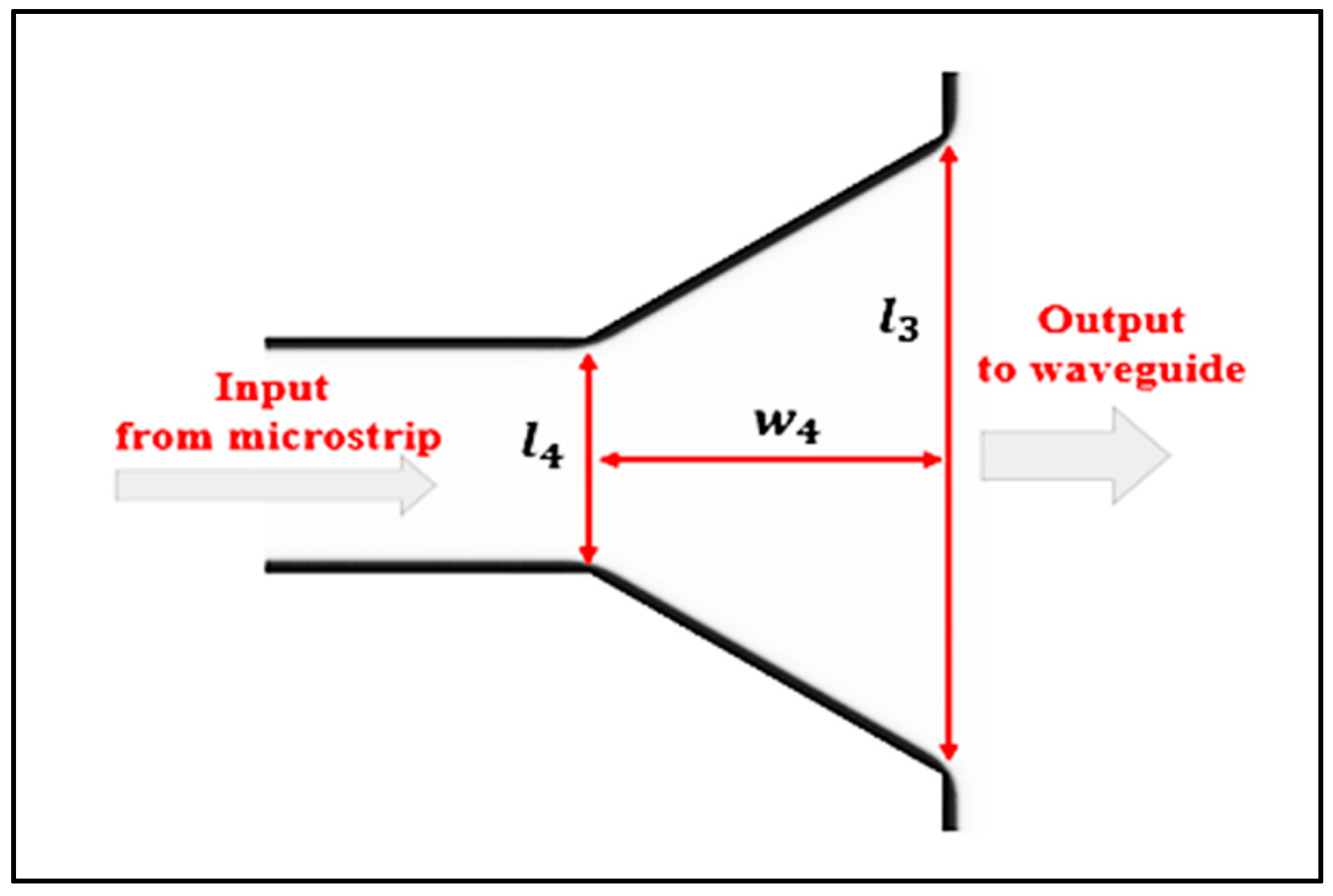
To achieve optimal impedance matching between the feeding network and the antenna structure, a tapered transition is strategically employed [26]. This transition is critical in minimizing reflection losses and ensuring efficient energy transfer, particularly in high-frequency antenna systems where abrupt impedance discontinuities can severely degrade performance [27]. Two configurations are commonly used to transform from microstrip to Dielectric-Filled Rectangular Waveguide (DFRW) [28]. The first approach uses a multi-section Chebyshev impedance transformer. The second one consists of a linear taper that matches the microstrip line impedance with the DFRW impedance. In microstrip antenna (MSA) design, tapered transitions are widely adopted to enhance bandwidth, impedance matching, and radiation efficiency. In this work, both approaches were considered. While Chebyshev sections offer excellent narrowband matching, their stepping discontinuities at W-band introduce fabrication sensitivity and additional parasitic reflections. In contrast, a linear taper provides a monotonic impedance profile and smoother broadband matching across 75–110 GHz with lower tolerance sensitivity. Therefore, the linear taper was selected for the proposed design. The topology of the implemented transition follows the second approach, as illustrated in Figure 4.
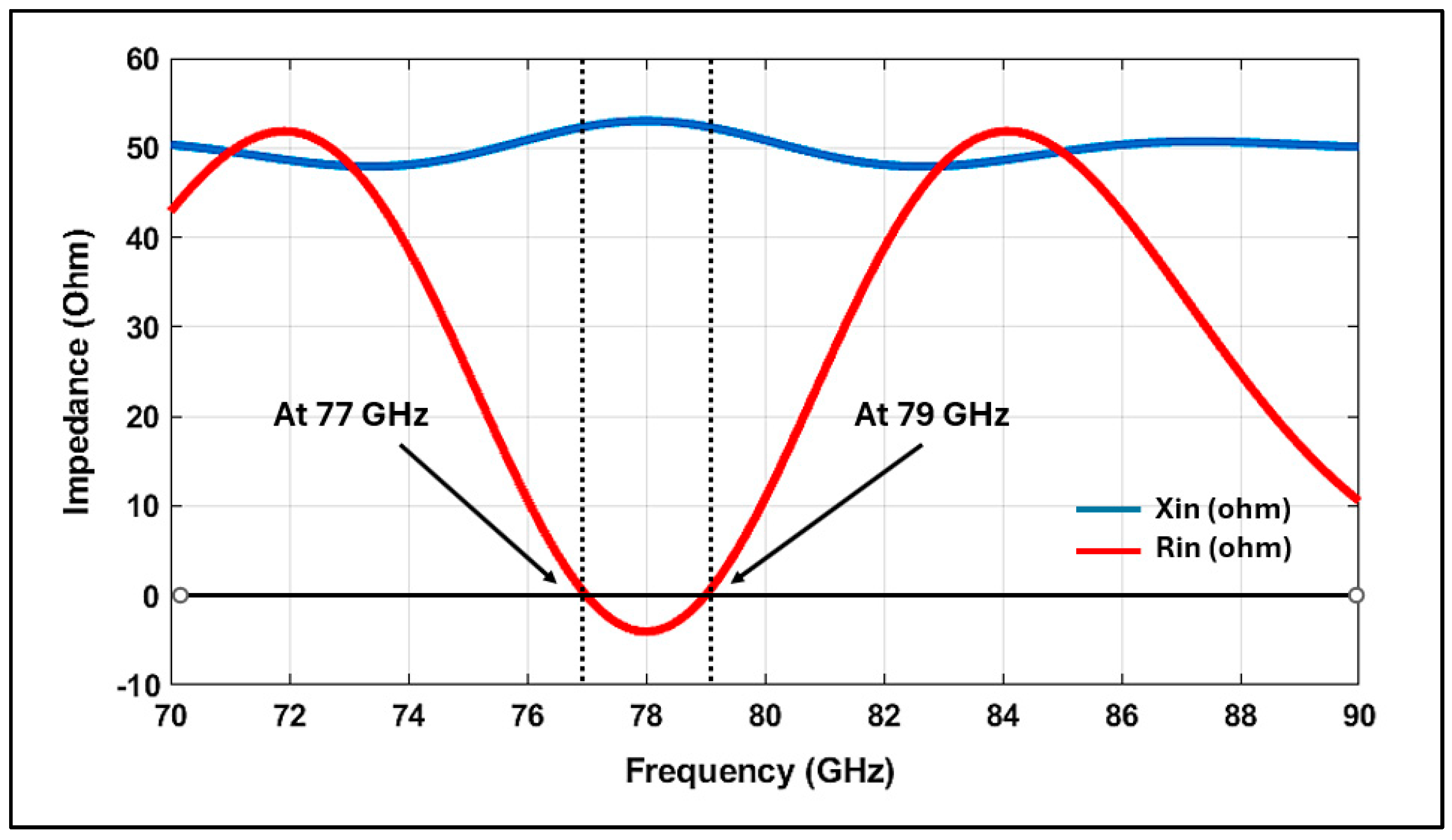
Figure 5 presents the input impedance (Rin and Xin) as a function of frequency, with arrows marking 77 and 79 GHz, where Xin = 0 coincides with the S11 minima and realized-gain peaks. The plot confirms the broad banding mechanism: the reactance (Xin) crosses zero at 77 and 79 GHz while Rin ≈ 50 Ω, validating the presence of true resonances aligned with the S11 dips. Between these resonances, the linear taper behaves as a quasi-continuous transformer, while the shorting vias introduce shunt inductance that reduces the reactance slope, maintaining |Γ| at a low level across 77–79 GHz. Beyond this band, Xin increases, leading to a mismatch and explaining the observed multi-resonance behavior that results in the achieved −10 dB bandwidth.
The tapered transition of the proposed design is characterized by three main parameters: the transition length w 4 , the width l 3 , and the initial width l 4 . Consequently, l 4 must be calculated to obtain the desired characteristic impedance [29]. This width is selected to achieve a characteristic impedance of 50 Ω, and by calculating the ratio ( l 4 h ) as “ h ” is the substrate height, it becomes easy to evaluate the value of l 4 by the following formula:
l 4 h = 8 e M e 2 M 2                                                                                                                                                                                                         f o r   l 4 h < 2   2 π B 1 ln 2 B 1 + ε r 1 2 ε r ln B 1 + 0.39 0.61 ε r       f o r   l 4 h > 2
In standard closed-form models for microstrip lines, two auxiliary parameters, M and B, are introduced, defined as
M = z 0 60 ε r + 1 2 + ε r 1 ε r + 1 ( 0.23 + 0.11 ε r ) ,
B = 377 π 2 Z 0 ε r
These parameters are used to compute the effective width and impedance of the tapered section. The equivalent waveguide width a e can then be obtained by equating the right-hand sides of Equations (1) and (4), and solving it ( l e is the width of an equivalent waveguide) [30].
Here a e denotes the effective characteristic-admittance parameter of the microstrip section. It is defined from the local characteristic impedance Z0 (W/h, εeff) as
1 a e = Z 0 η 0 h
1 a e = 60 η 0 h ln 8 h l 3 + 0.25 l 3 h                                                                                                   f o r   1 l e < 2 120 π η 0 h ( l 3 h + 1.393 + 0.667   l n ( l 3 h + 1.444 ) 0.627 ε r ε r + 1 2 + ε r 1 2 1 1 + 12 h l 3                         f o r   1 l e < 2
where η 0 = μ 0 ε 0 377 Ω is the free-space wave impedance.
1 l e = 4.38 l 2 e
where l 2 is the width of the substrate, which is connected to the cavity as illustrated in Figure 4 and listed in Table 2. The effective permittivity of a line of width w is approximated by the Hammerstad Jensen model [31]:
ε e f f 2 ε r + 1 2 + 2 ε r 1 2 1 1 + 12 h / ω + 0.04   ( 1 ω h ) 2
At 77 GHz, the free-space wavelength is
λ 0 = c f 3 × 10 8 77 × 10 9 3.90   m m ,
and the guided wavelength is λ g = λ 0 ε e f f . For ε r = 2.2 and practical ( ω / h ) in our stack, ε e f f lies near 1.6–1.8; taking ε e f f 1.7 gives λ g 3.90 / 1.7 2.99   mm and thus a quarter-wave taper length of:
l t λ g / 4 0.75   mm   ( at   77   GHz ) .

2.2. Impact of Short Pins on Antenna Performance and Design

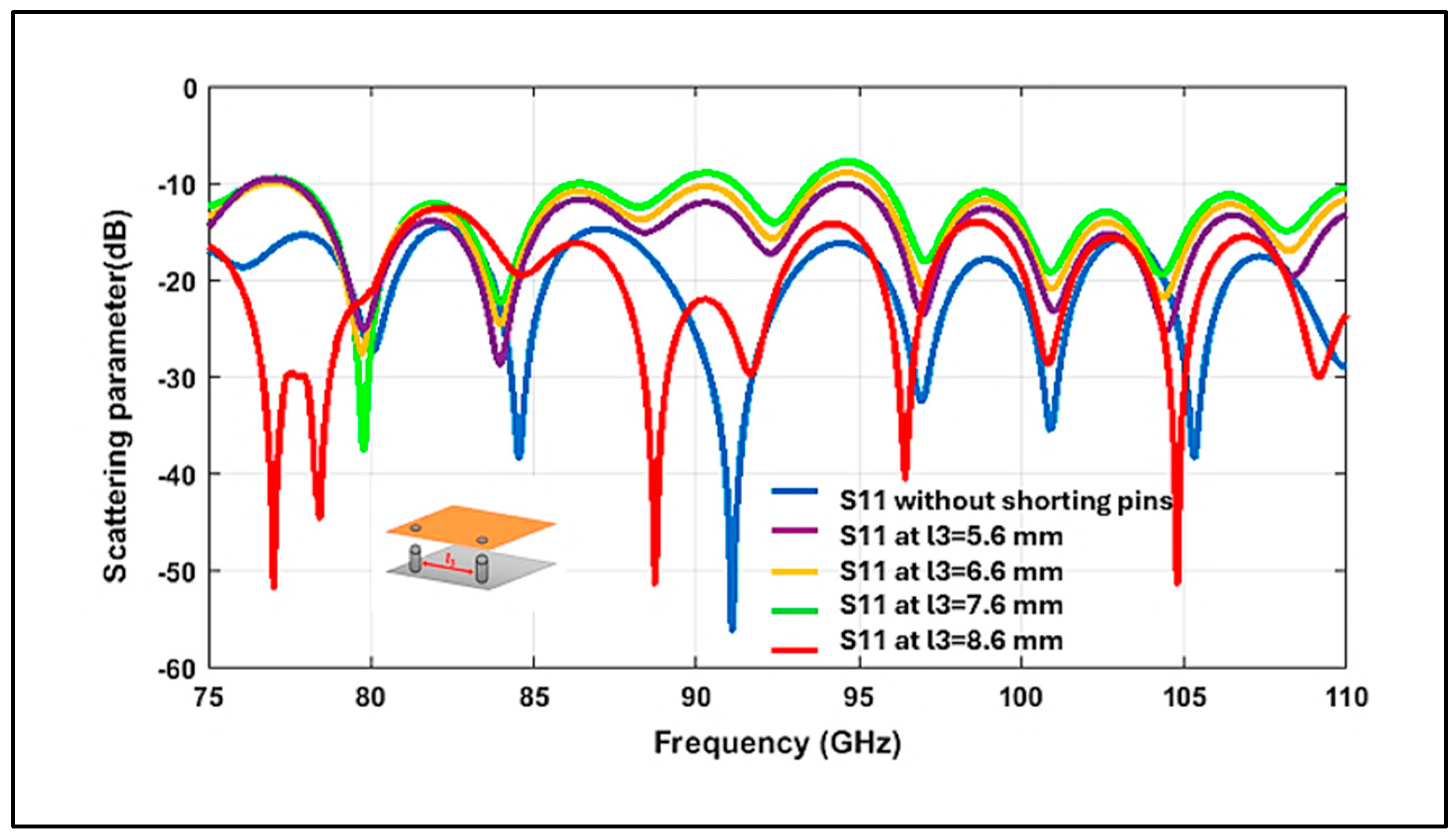
Shorting vias (or pins) are essential in MSA designs, particularly for high-frequency applications in the 75–110 GHz band [32]. They improve performance by minimizing parasitic effects, enhancing electrical connectivity, and creating vertical conductive paths within the substrate. This reduces radiation losses and increases antenna efficiency and gain [33]. The placement and diameter of these vias strongly influence wave propagation and overall electromagnetic performance, making their optimization critical for high-frequency operation. Figure 6 illustrates the impact of via spacing on the reflection coefficient. Introducing shorting vias flattens the reactance curve Xin(f), producing a continuous (~−15 dB) matching region across 77–79 GHz. In contrast, the case without shorting vias exhibits a more reactive (capacitive/inductive) input impedance and poor low-frequency matching. The optimum via spacing results in the deepest S11 minima at both band anchors while preserving the overall bandwidth.
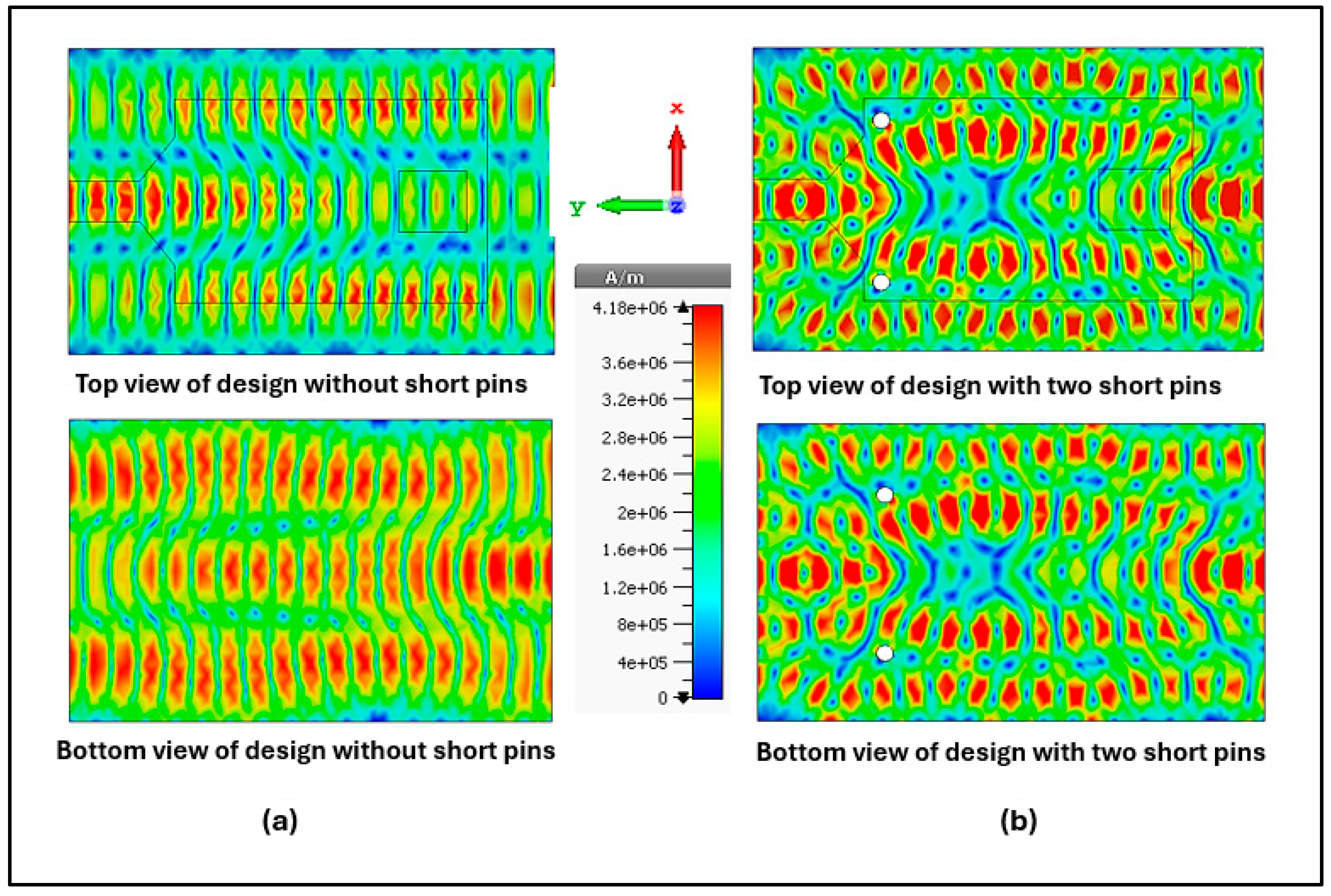
Figure 7 compares the surface current distributions with and without shorting vias. Without vias, the current flows more uniformly across the patch, producing broad but weakly defined regions of high and low current density. In contrast, when vias are introduced, the current becomes strongly concentrated near the via locations, forming localized high-density regions. Each shorting via behaves as a shunt inductive path to ground, which compensates for the distributed slot/microstrip capacitance. A widely used approximation for the partial inductance of a vertical via of length h and barrel diameter d as in Equation (7):
L v i a μ 0 h 2 π [ ln 4 h d + 1 ]   H ,
with μ 0 = 4 π × 10 7   H / m , h in meters, d in meters. With two identical vias in parallel, the effective shunt inductance is L s h L v i a / 2 (neglecting minor spreading/pad effects). The AC resistance is small at W-band (copper, σ 5.8 × 10 7 S/m), with skin depth δ = 2 / ( ω μ 0 σ ) 0.76 μm at 77 GHz; R v i a l / ( σ   2 π ( d / 2 )   δ ) is ( 10   m Ω ) and negligible versus | X L | = ω L 10 2   Ω .
This results in a stable −10 dB matching band. The presence of vias therefore produces a more complex and spatially varied current distribution, directly contributing to improved impedance matching and bandwidth control.
The etched slot is necessary to confine and steer the field under the patch, flatten the input reactance slope, and together with the shorting vias realize the dual-resonance match across 77–79 GHz. The |E| field maps reveal slot-induced cavity confinement beneath the patch, which helps moderate Xin. The slight antinode shifts observed between 77 and 79 GHz correspond to the S11 minima and Xin ≈ 0 crossings, explaining the stable matching in this band.
A slot is integrated into the patch to engineer the surface-current path and phase, reshaping the active aperture toward the end-fire direction and thereby tightening the main beam and increasing the realized gain while maintaining the required S11 match.

3. Results and Discussion

The simulated radiation efficiency is calculated as follows [34]:
η r a d = 1 L o s s c o p p e r L o s s d i e l e c t r i c L o s s m i s m a t c h
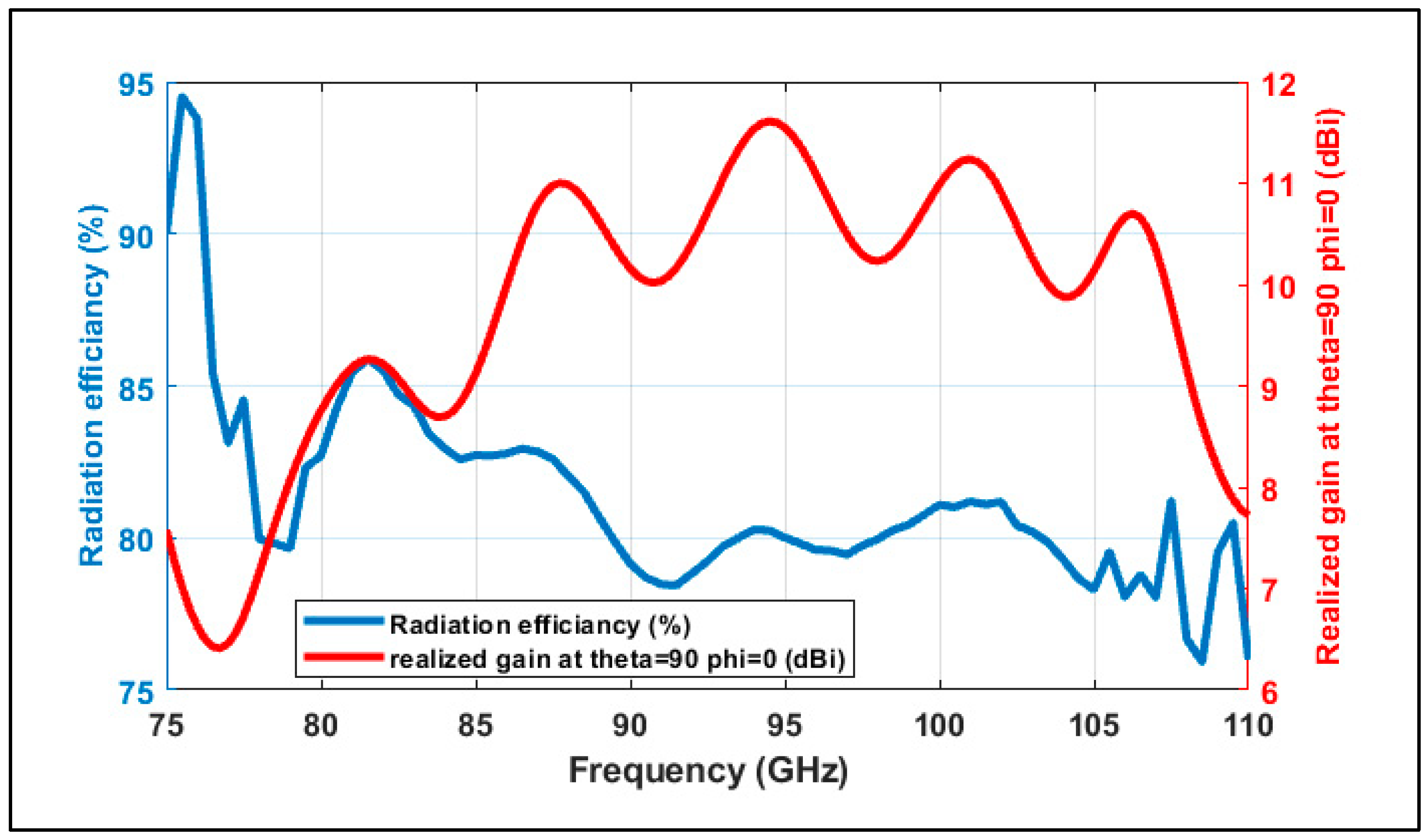
where L o s s c o p p e r , L o s s d i e l e c t r i c , and L o s s m i s s m a t c h are losses in the copper conductors, dielectric, and mismatch. The simulated radiation efficiency accounting for conductor, dielectric, and mismatch losses exceeded 85% at 77 GHz owing to the low-loss PCB stack-up. Figure 8 plots radiation efficiency and end-fire realized gain at θ = 90°, φ = 0° over the 75 to 110 GHz range, with efficiency mostly ~78–92% and a smooth, quasi-periodic gain profile. At the ADAS band edges, performance is strong: ≈9.9 dBi/≈85% at 77 GHz and ≈11.2 dBi/≈80% at 79 GHz. The stable traces around 77–79 GHz indicate consistent aperture excitation rather than loss-driven variation, confirming robust forward directivity with low dissipation.
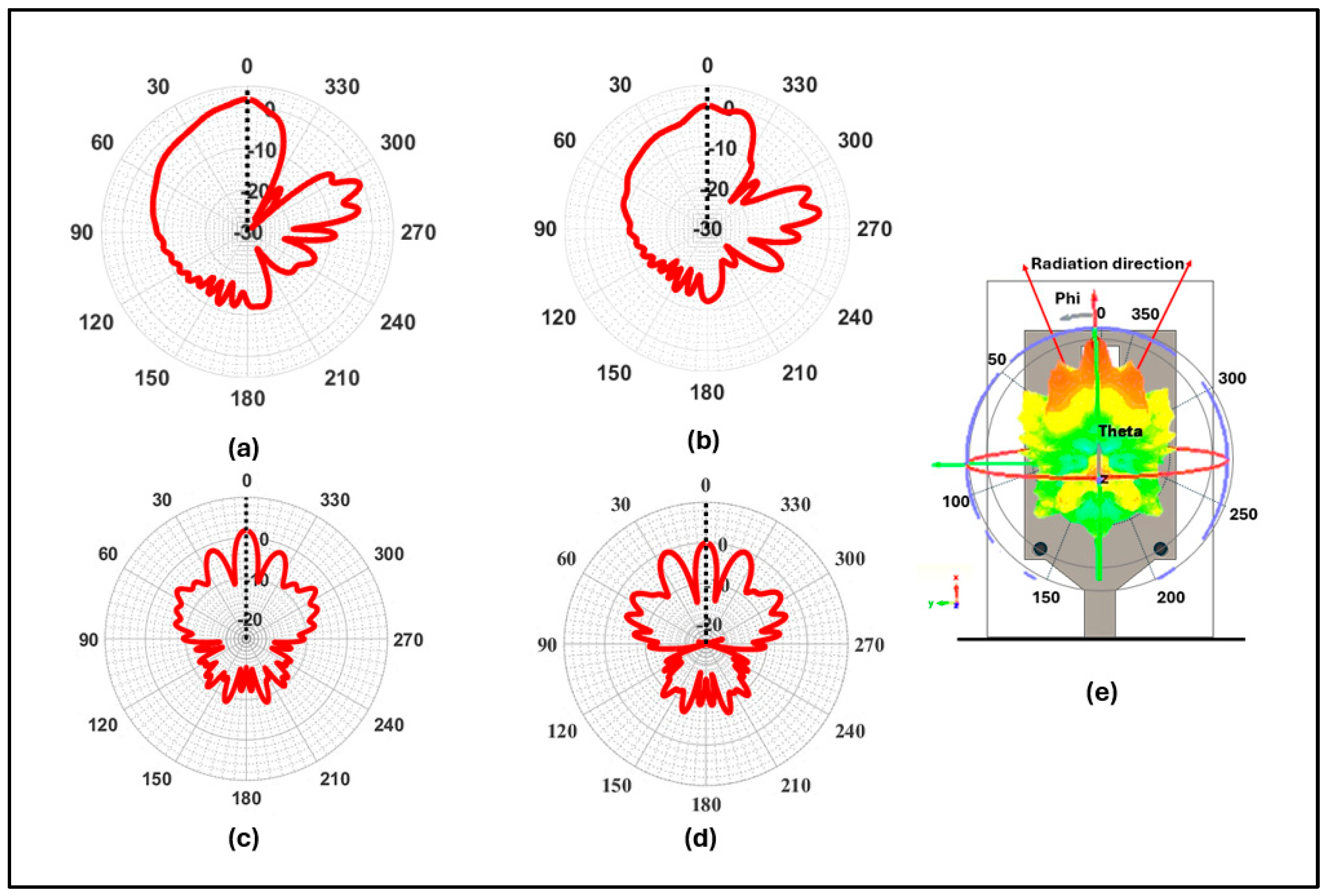
Figure 9a–d present the normalized total electric field | E | (dB) in IEEE spherical coordinates: θ-cut (φ = 0°) and φ-cut (θ = 90°) at 77/79 GHz. The patterns exhibit a stable, forward-pointing end-fire main beam with the radiation maximum near θ ≈ 90°, and a consistent −3 dB beamwidth (~40–60°) across frequency. Sidelobes are well suppressed, and back radiation is low, yielding a high F/B ratio. Together with the angular reference in Figure 9e, these results confirm wideband stability suitable for automotive radar/ADAS.
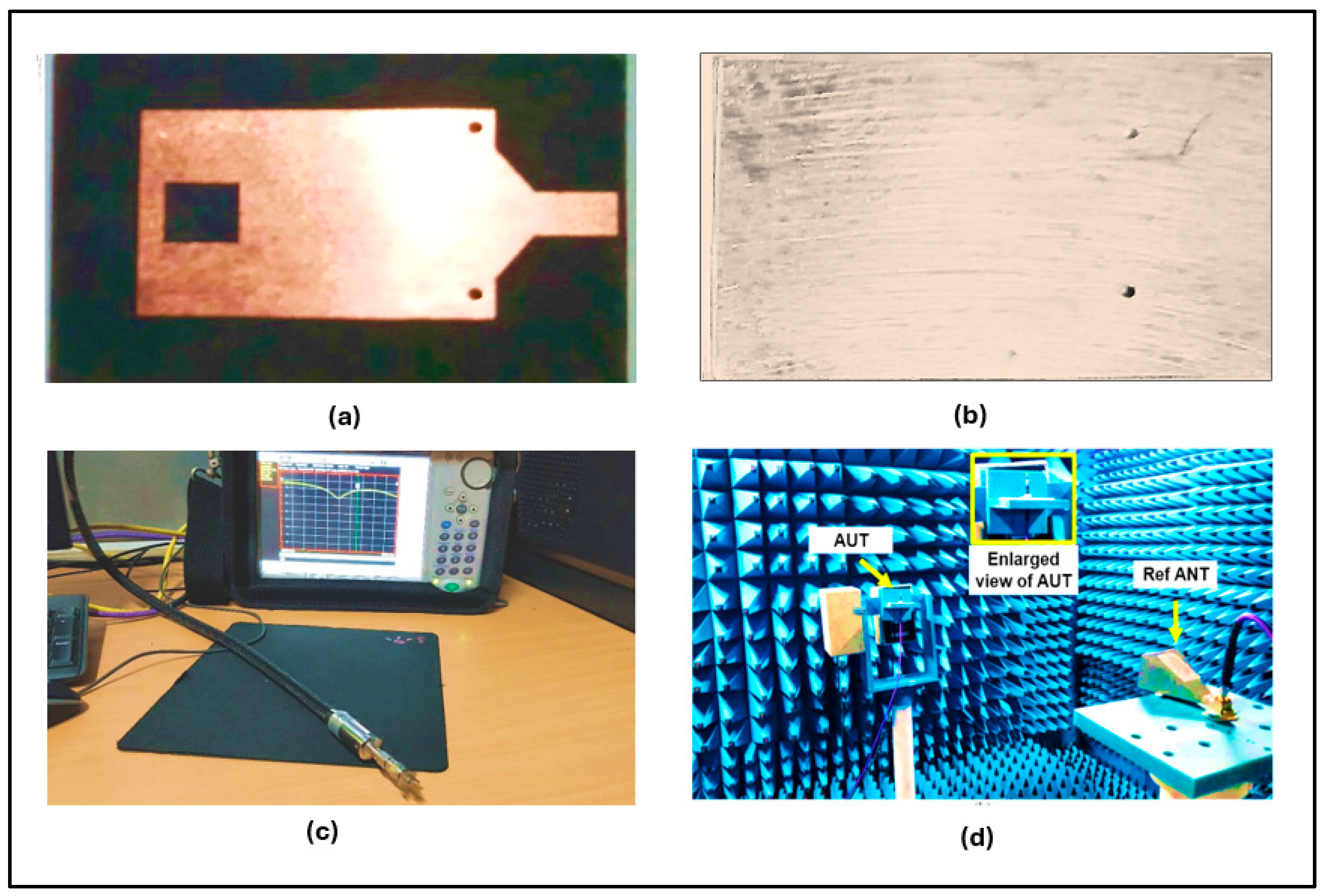
Figure 10 documents the fabricated PCB and the WR-12 launcher-based metrology used for both S11 and far-field characterization, including TRL de-embedding to the microstrip feed plane. Far-field realized gain was measured in a fully anechoic chamber using the comparison (substitution) method with a calibrated WR-12 standard-gain horn. The AUT was placed beyond the Fraunhofer distance, polarization was aligned, and the VNA reference plane was TRL de-embedded to the microstrip feed. Realized gain was obtained from G A U T θ , f = G r e f f + S 21 , A U T θ , f S 21 , r e f f , with measurement uncertainty of ±0.5 dB (amplitude) and ±1° (pointing). Prototype fabricated on εr = 2.2, h = 0.762 mm laminate with copper thickness (35 μm). Shorting vias: finished drill 0.25 mm, drilling precision ±0.05 mm, plating thickness ≥ 25 μm (hole wall). Slot/patch etch tolerance ≤ ±0.02 mm. Surface finish ENIG (Ni 3–6 μm, Au 0.05–0.1 μm).
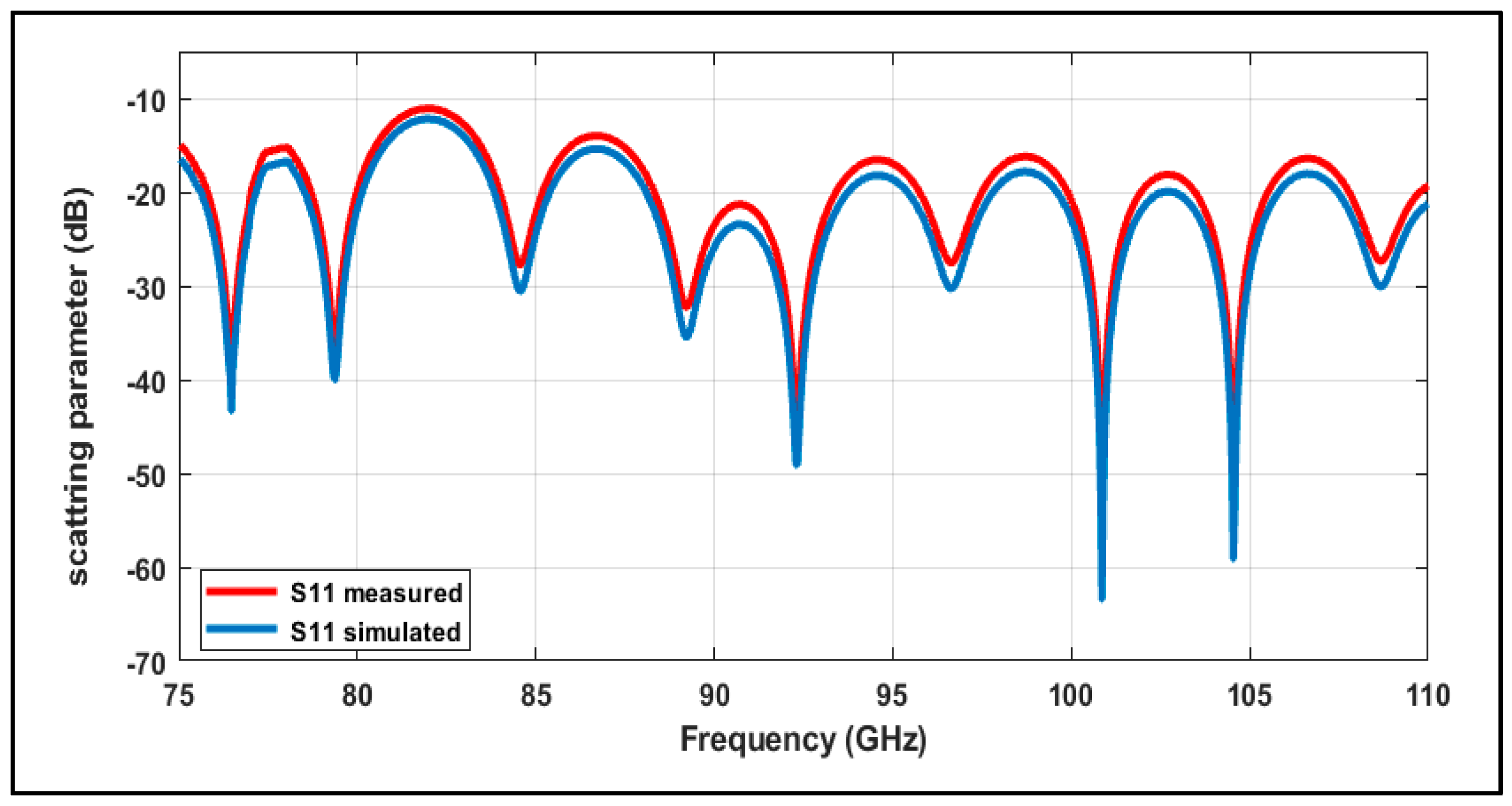
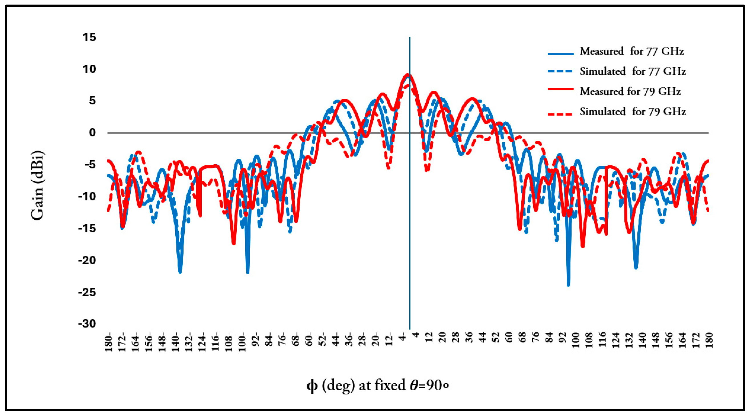
The measured S11 in Figure 11 confirms robust matching centered at 77/79 GHz and higher frequencies on band, with minor simulation-to-measurement deviations attributed to fabrication tolerances and material dispersion. Figure 12 overlays the measured and simulated co-polar realized gain at 77 GHz and 79 GHz plotted versus φ ∈ [−180°, +180°] at θ = 90°. The measured main-lobe peaks (≈9.9 dBi and ≈11.2 dBi) and ≥18 dB cross-polar suppression corroborate the simulations; pointing uncertainty is ±1° for both measurement and simulation. Figure 9 presents the normalized total field | E | (dB) cuts, each normalized to its own peak: (a, b) θ-plane ( ϕ = 0 ° ) at 77/79 GHz, and (c, d) φ-plane ( θ = 90 ° ) at 77/79 GHz. Unless stated otherwise, φ-plane patterns are plotted as | E | ( ϕ ) at θ = 90 ° , ensuring consistency with Figure 9c,d and symmetry about ϕ = 0 ° . Unless stated otherwise, φ-plane patterns are plotted as | E | ( φ ) at θ = 90°, ensuring consistency with Figure 9c,d and symmetry about φ = 0°.
Table 3 benchmarks the design against related work, highlighting the compact PCB-compatible footprint, high efficiency, and competitive gain without multilayer or waveguide-only complexity. These results validate the antenna’s suitability for ADAS applications requiring focused and reliable forward-looking signal transmission [35].

4. Thermal Impact on Antenna Geometry and Resonance in ADAS Applications

Radar applications operating in the 77 GHz,79 GHz band, particularly for automotive ADAS systems, are often deployed in environments subject to wide temperature variations (e.g., –40 °C to +105 °C), depending on weather, engine proximity, and mounting location [40]. These thermal fluctuations induce dimensional changes in the antenna structure due to the coefficient of thermal expansion (CTE) of the conductive and dielectric materials, which in turn affect the antenna’s electrical performance, most notably the resonance frequency [41].
To analytically estimate the thermal impact, the standard linear expansion model was applied as in Equation (9) [42]:
L L 0 1 . f 0 f r T                   T . L 0 .   =   L
where α (alpha) is the thermal expansion coefficient (for copper, = 7 × 10 6   ° C 1 ) , L0 is the initial patch length, ∆T is the change in temperature, and f0 is the design frequency at nominal conditions (77.08 GHz at 25 °C).
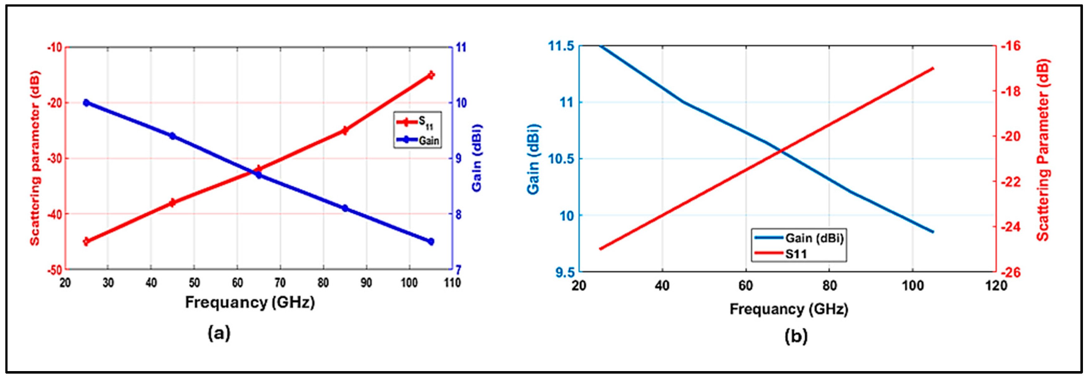
Assuming a rectangular patch antenna with dimensions L0 = 23.6 mm and W0 = 15.0 mm, Table 4 summarizes the dimensional changes and corresponding resonance frequency shift and gain across various operating temperatures. Resonant drift is fitted linearly, f ( T ) = f 0 + k T (25–105 °C), yielding R 2 0.98 . Pre-tuning from T c a l to T t a r g e t uses f c a l = f t a r g e t k   ( T t a r g e t T c a l ) ; applied at 77.79 GHz for 85/105 °C, this aligns the | S 11 | minima within fit tolerance and ≤±0.5 dB gain change as in Figure 13.
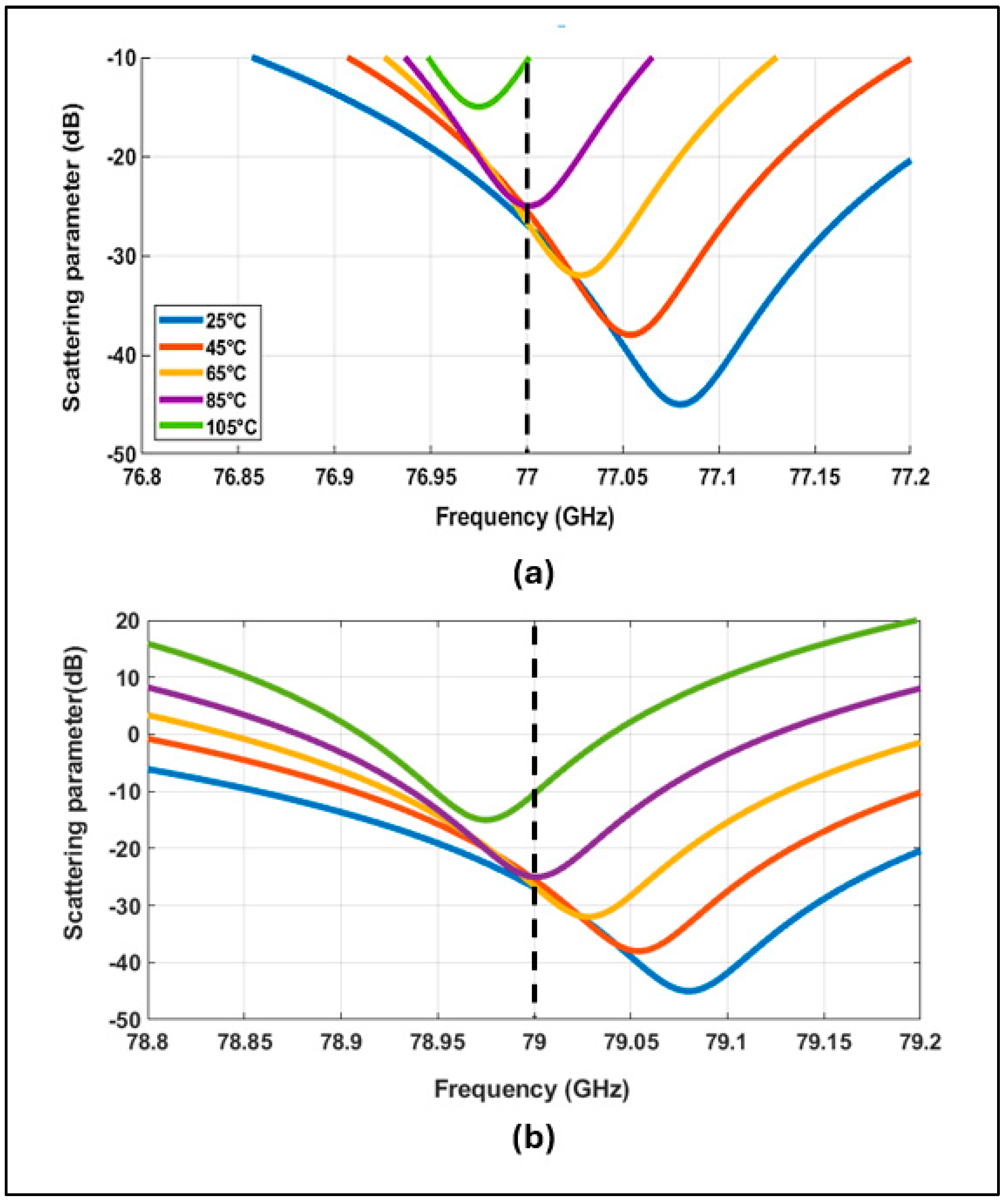
For completeness, Figure 14 reports the temperature dependence of the match on both band anchors. Panels (a) and (b) sweep S11 around 77 GHz and 79 GHz, respectively, for 25–105 °C. In both cases, the resonance remains within ≈±0.05–0.10 GHz of the anchor, and the return loss is ≥10 dB at/near the anchor across the sweep, confirming robust matching at both 77 and 79 GHz.
To counteract the thermally induced resonance shift, the antenna was pre-tuned to 77.08 GHz and 79.06 GHz at 25 °C to ensure precise alignment with the target 77.00 GHz and 79 GHz under elevated temperature conditions (~85 °C). This thermal pre-tuning strategy effectively mitigates performance degradation caused by dimensional expansion, allowing the antenna to maintain optimal impedance matching and gain stability across the intended thermal range. Such an approach is critical for ensuring robust and reliable operation in ADAS radar applications, where high thermal variability is common.

5. Integration and Simulation of the Proposed Antenna in ADAS-Enabled Environments

5.1. Initial Evaluation of Vehicle-Mounted Antenna in ADAS

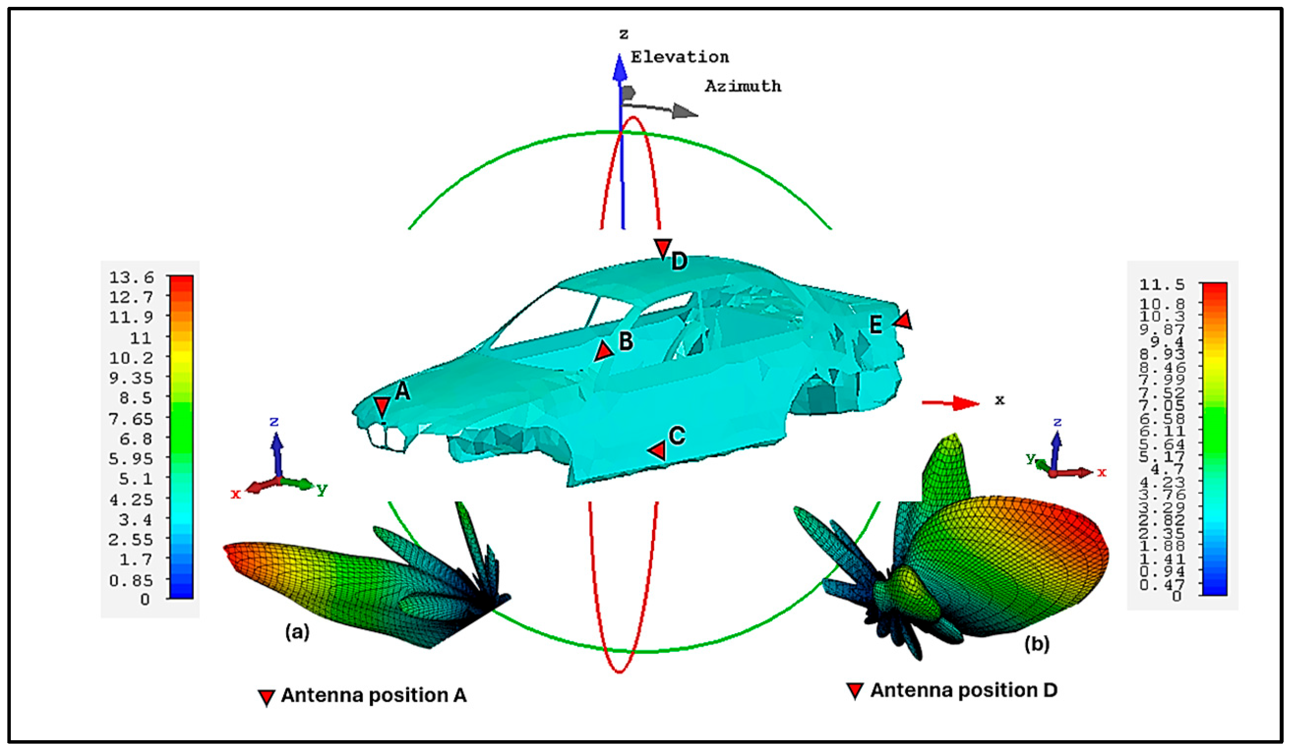
After designing the 77, 79 GHz microstrip antenna and obtaining promising simulation results, a realistic automotive environment was constructed to assess its practical performance. The primary objective was to evaluate the antenna’s effectiveness within ADAS and V2X communication systems [43]. As illustrated in Figure 15, electromagnetic simulations were conducted using the WIPL-D ProCAD 2024 Demo [44], where the antenna was integrated onto a detailed vehicle body model to reflect real-world installation conditions.
Effect of the roof plate at location D. The metallic roof forms a nearby conducting surface that is excited by the antenna’s near field, producing image currents. The resulting field can be interpreted as E d i r θ , φ + ρ ( φ ) E d i r θ , φ e j 2 k h c o s θ , which biases radiation toward the forward hemisphere and can tilt the main lobe by a few degrees while slightly modifying beamwidth/directivity.
The simulations highlighted the influence of the car’s physical structure on radiation characteristics such as beam direction, realized gain, and the presence of side lobes. This in situ evaluation provided critical insights into the antenna’s real-world behavior, underlining the necessity of environment-aware design approaches in automotive radar systems.
Moreover, the positioning of antennas for applications like Adaptive Cruise Control (ACC) and Automatic Emergency Braking (AEB) must follow specific guidelines to ensure optimal performance and safety [45]. An unobstructed field of view is essential, typically covering horizontal angles of 20–40° and vertical angles of 10–15° to reliably detect surrounding vehicles and obstacles [46]. Standard installation height ranges from 0.4 to 0.8 m above ground level (usually near the front bumper or grille), with a slight downward tilt of 1–2 degrees to enhance ground-level object detection and forward-looking radar coverage.
Tx–Rx isolation is ultimately set by the module/array (spacing, filtering/duplexing, shielding); the proposed single-pol element, co-pol dominated with low sidelobes, readily supports high isolation when orthogonally paired or modestly spaced, with absolute isolation determined by the final module architecture.
Outside 77–79 GHz, higher-order slot/taper modes provide ~3–6 dB antenna-level discrimination; with standard 20–40 dB front-end filtering, this exceeds 23–46 dB isolation suitable for Tx–Rx isolation.

5.2. Virtual Scenario for Smart Road Deployment

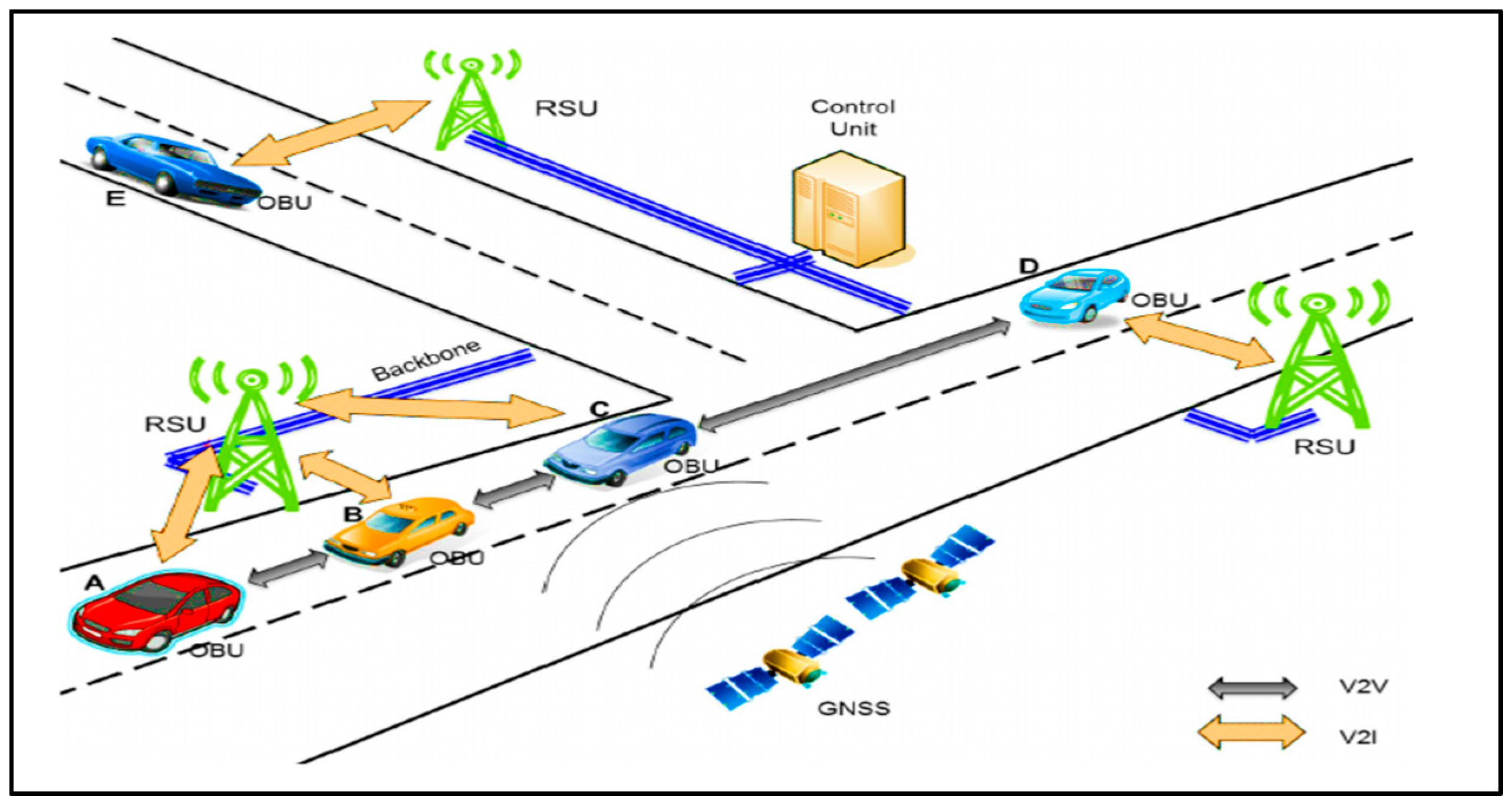
The system architecture illustrated in Figure 16 serves as a representative model of an ADAS-enabled vehicular communication network. It captures the dynamic interaction between vehicles and infrastructure through integrated Vehicle-to-Vehicle (V2V) and Vehicle-to-Infrastructure (V2I) communication links. These connections are facilitated by On-Board Units (OBUs), Roadside Units (RSUs), a centralized control node, and Global Navigation Satellite System (GNSS)-based positioning mechanisms [47].
In the illustrated scenario, vehicles A, B, and C actively participate in both V2V and V2I communications. Their OBUs continuously exchange real-time data with nearby RSUs, enabling the dissemination of traffic conditions, hazard alerts, and other critical situational awareness information. Vehicle D, as it approaches a signalized intersection, benefits from coordinated data inputs received from both the RSU and the central control node, thereby enhancing its decision-making processes for safer navigation.
Conversely, vehicle E exemplifies the implementation of high-speed V2V communication, leveraging GNSS-based localization to maintain safe inter-vehicle spacing and accurate lane tracking. This interconnected communication ecosystem enables a high level of cooperative awareness, forming the operational basis for key ADAS features such as adaptive cruise control, automatic emergency braking, and real-time collision prediction.

5.3. Impact of Non-Embedded Antennas on Smart Road Performance

Without embedded antenna integration within smart road infrastructure, advanced ADAS encounter significant limitations in terms of coverage precision and communication latency. In such scenarios, vehicles must rely solely on their OBUs and internal sensors, which reduces their situational awareness, especially in complex urban areas or locations with weak signal coverage.
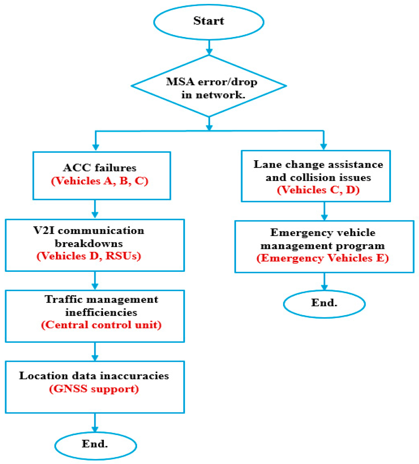
Figure 17 illustrates a common failure scenario caused by antenna system defects or misconfigurations. These vulnerabilities lead to communication breakdowns and delayed responses in safety-critical functions.
For instance, Vehicle D approaching an intersection may fail to receive timely alerts from the RSU, impairing its ability to anticipate hidden hazards or react to cross-traffic. Similarly, Vehicle E, which depends primarily on V2V communication, might suffer from data delays due to interference or temporary signal loss. Such latencies compromise features like automatic braking and proactive lane shifting.
Furthermore, the absence of embedded antennas results in discontinuous and uncoordinated coverage across the road network, leading to awareness gaps between vehicles and diminishing the reliability of cooperative perception and semi-autonomous functions. Therefore, integrating high-performance microstrip antennas into road infrastructure is essential for robust ADAS operation. This underlines the urgent need for integrated solutions that merge advanced antenna technologies with smart roadway systems.

6. Conclusions

This work demonstrated a compact, single-layer W-band PCB antenna tailored to the 77–79 GHz ADAS band and validated via a launcher-based measurement workflow (WR-12 TRL de-embedding with anechoic-chamber substitution). The prototype achieves a robust match (S11 ≤ −10 dB across 77–79 GHz) and end-fire radiation with realized gains of ≈9.9/≈11.2 dBi at 77/79 GHz, ≥18 dB cross-polar suppression in the main beam, and well-controlled sidelobes. The measured −3 dB beamwidths are ≈36° in the θ-cut (φ = 0) and ≈11.6° in the φ-cut (θ = 90°), consistent with full-wave simulations. A controlled thermal sweep from 25 to 105 °C yields < 100 MHz resonance drift while maintaining ≥ 10 dB return loss, confirming thermal robustness. Combined with high simulated radiation efficiency (≈85% at 77 GHz; ≈80% at 79 GHz) and gain flatness of ~1.3 dB across 77–79 GHz, the element is well-suited for short- and medium-range automotive radar. Future research will extend this design to higher mmWave bands (up to 220 GHz) for next-generation 6G, IoT, and V2X applications.

Author Contributions

The research was conceptualized and designed by A.M.A., who conducted the design simulations and validation of the proposed design and drafted the manuscript. A.S.A.E.-H. performed data analysis and contributed to the preparation of figures and visual representations. A.R.E. was responsible for the experimental setup, including fabrication, as well as ensuring the accuracy of measurement protocols. H.M.E.-H. supervised the study and provided critical revisions to enhance the intellectual content of the manuscript. A.S.A.E.-H., as the corresponding author, coordinated the collaboration among all team members, integrated feedback from all contributors, and ensured the manuscript adhered to publication standards. All authors have read and agreed to the published version of the manuscript.

Funding

This research received no external funding.

Institutional Review Board Statement

Not applicable.

Informed Consent Statement

Not applicable.

Data Availability Statement

The data presented in this study are available upon request from the corresponding author. Due to privacy restrictions, they are not publicly available.

Acknowledgments

The authors gratefully acknowledge the National Telecommunications Institute (NTI), Egypt for fabrication support and the Electronics Research Institute (ERI), Egypt for providing access to the RF measurement facilities.

Conflicts of Interest

The authors declare no conflicts of interest.

References

  1. Boban, M.; Kousaridas, A.; Manolakis, K.; Eichinger, J.; Xu, W. Connected Roads of the Future: Use Cases, Requirements, and Design Considerations for Vehicle-to-Everything Communications. IEEE Veh. Technol. Mag. 2018, 13, 110–123. [Google Scholar] [CrossRef]
  2. Sadaf, M.; Iqbal, Z.; Javed, A.R.; Saba, I.; Krichen, M.; Majeed, S.; Raza, A. Connected and Automated Vehicles: Infrastructure, Applications, Security, Critical Challenges, and Future Aspects. Technologies 2023, 11, 117. [Google Scholar] [CrossRef]
  3. Dey, K.C.; Yan, L.; Wang, X.; Wang, Y.; Shen, H.; Chowdhury, M.; Yu, L.; Qiu, C.; Soundararaj, V. A Review of Communication, Driver Characteristics, and Controls Aspects of Cooperative Adaptive Cruise Control (CACC). IEEE Trans. Intell. Transport. Syst. 2016, 17, 491–509. [Google Scholar] [CrossRef]
  4. National Safety Council. Available online: https://www.nsc.org/?srsltid=AfmBOoo7_Gti24ezHf8cWurD8fIpa6R_vGLYJ9-EbyV12Jj-10_rt9K (accessed on 15 November 2025).
  5. Wang, H.; Feng, Y.; Tian, Y.; Wang, Z.; Hu, J.; Tomizuka, M. Towards the Next Level of Vehicle Automation Through Cooperative Driving: A Roadmap from Planning and Control Perspective. IEEE Trans. Intell. Veh. 2024, 9, 4335–4347. [Google Scholar] [CrossRef]
  6. ISO 26262:2024; Road Vehicles Functional Safety. International Organization for Standardization (ISO): Geneva, Switzerland, 2024.
  7. Shaikh, F. Advance Driver Assistance Systems (ADAS); Technical Report; Technische Universität Chemnitz: Chemnitz, Germany, 2024. [Google Scholar] [CrossRef]
  8. Bathla, G.; Bhadane, K.; Singh, R.K.; Kumar, R.; Aluvalu, R.; Krishnamurthi, R.; Kumar, A.; Thakur, R.N.; Basheer, S. Autonomous Vehicles and Intelligent Automation: Applications, Challenges, and Opportunities. Mob. Inf. Syst. 2022, 2022, 7632892. [Google Scholar] [CrossRef]
  9. Sayem, N.M.; Baki, A.K.M.; Faysal, F.; Mahmud, S.T.; Jubayer, A.; Rifat, T.A. Development of Novel and High Gain Microstrip Patch Antennas at Different Frequency Bands for 6g Applications. PIER C 2023, 137, 263–275. [Google Scholar] [CrossRef]
  10. Nagy, L. Microstrip Antenna Development for Radar Sensor. Sensors 2023, 23, 909. [Google Scholar] [CrossRef]
  11. Islam, Z.U.; Bermak, A.; Wang, B. A Review of Microstrip Patch Antenna-Based Passive Sensors. Sensors 2024, 24, 6355. [Google Scholar] [CrossRef]
  12. Zhu, J.; Liu, J. Design of Microstrip Antenna Integrating 24 GHz and 77 GHz Compact High-Gain Arrays. Sensors 2025, 25, 481. [Google Scholar] [CrossRef]
  13. Bu, D.; Qu, S. Magneto-electric Dipole Antenna Array for 77 GHz Automotive Radar. IET Microw. Antenna Amp. Prop. 2024, 18, 96–105. [Google Scholar] [CrossRef]
  14. Yeap, S.B.; Qing, X.; Chen, Z.N. 77-GHz Dual-Layer Transmit-Array for Automotive Radar Applications. IEEE Trans. Antennas Propag. 2015, 63, 2833–2837. [Google Scholar] [CrossRef]
  15. Su, G.-R.; Li, E.S.; Kuo, T.-W.; Jin, H.; Chiang, Y.-C.; Chin, K.-S. 79-GHz Wide-Beam Microstrip Patch Antenna and Antenna Array for Millimeter-Wave Applications. IEEE Access 2020, 8, 200823–200833. [Google Scholar] [CrossRef]
  16. Zang, Z.; Zaman, A.U.; Yang, J. Single-Layer Dual-Circularly Polarized Series-Fed Gap Waveguide-Based Slot Array for a 77 GHz Automotive Radar. IEEE Trans. Antennas Propag. 2023, 71, 3775–3784. [Google Scholar] [CrossRef]
  17. Zubair, M.; Jabbar, A.; Tahir, F.A.; Kazim, J.U.R.; Rehman, M.U.; Imran, M.; Liu, B.; Abbasi, Q.H. A High-Performance Sub-THz Planar Antenna Array for THz Sensing and Imaging Applications. Sci. Rep. 2024, 14, 17030. [Google Scholar] [CrossRef] [PubMed]
  18. Li, Y.; Ma, H.; Peng, H.; Liu, H. W-Band Microstrip Antenna Arrays on Glass. Electronics 2025, 14, 2133. [Google Scholar] [CrossRef]
  19. Teng, L.; Yu, Z.; Zhu, D.; Hao, C.; Jiang, N. Antenna Array Design Based on Low-Temperature Co-Fired Ceramics. Micromachines 2024, 15, 669. [Google Scholar] [CrossRef] [PubMed]
  20. Lan, S.; Huang, C.; Wang, Z.; Liang, H.; Su, W.; Zhu, Q. Design Automation for Intelligent Automotive Systems. In Proceedings of the 2018 IEEE International Test Conference (ITC), Phoenix, AZ, USA, 29 October–1 November 2018; IEEE: New York, NY, USA, 2019; pp. 1–10. [Google Scholar]
  21. Pimentel, J. Rigorous Safety Analysis and Design of ADAS and ADS: Implications on Tools. arXiv 2024, arXiv:2406.08350. [Google Scholar] [CrossRef]
  22. Noor-A-Rahim, M.; Liu, Z.; Lee, H.; Khyam, M.O.; He, J.; Pesch, D.; Moessner, K.; Saad, W.; Poor, H.V. 6G for Vehicle-to-Everything (V2X) Communications: Enabling Technologies, Challenges, and Opportunities. Proc. IEEE 2022, 110, 712–734. [Google Scholar] [CrossRef]
  23. Mehta, A.A.; Padaria, A.A.; Bavisi, D.J.; Ukani, V.; Thakkar, P.; Geddam, R.; Kotecha, K.; Abraham, A. Securing the Future: A Comprehensive Review of Security Challenges and Solutions in Advanced Driver Assistance Systems. IEEE Access 2024, 12, 643–678. [Google Scholar] [CrossRef]
  24. Greco, F.; Arnieri, E.; Amendola, G.; De Marco, R.; Boccia, L. A 77 GHz Transmit Array for In-Package Automotive Radar Applications. Telecom 2024, 5, 792–803. [Google Scholar] [CrossRef]
  25. CST Studio Suite Electromagnetic Field Simulation Software. 2022. Available online: https://www.3ds.com/products-services/simulia/products/cst-studio-suite/ (accessed on 1 January 2025).
  26. Abada, A.M.; Abd El-Hameed, A.S.; Eldamak, A.R.; El-Hennawy, H.M. Design and Optimization of a High-Performance D-Band SIW Antenna for Future 6G IOT Applications. In Proceedings of the 2024 6th Novel Intelligent and Leading Emerging Sciences Conference (NILES), Giza, Egypt, 19–21 October 2024; IEEE: New York, NY, USA, 2024; pp. 123–126. [Google Scholar]
  27. Herfiah, S.; Rahayu, N.; Kurniawan, F.; Hasim, F.; Munir, A. Development of Monopulse Antenna Feeding System with Microstrip-Line-to-Waveguide-Transition Using SIW Technology. In Proceedings of the 2023 IEEE International Symposium on Antennas and Propagation and USNC-URSI Radio Science Meeting (USNC-URSI), Portland, OR, USA, 23–28 July 2023; IEEE: New York, NY, USA, 2023; pp. 1799–1800. [Google Scholar]
  28. Perez, J.M.; Rebollo, A.; Gonzalo, R.; Ederra, I. An Inline Microstrip-to-Waveguide Transition Operating in the Full W-Band Based on a Chebyshev Multisection Transformer. In Proceedings of the 2016 10th European Conference on Antennas and Propagation (EuCAP), Davos, Switzerland, 10–15 April 2016; IEEE: New York, NY, USA, 2016; pp. 1–4. [Google Scholar]
  29. Hecken, R.P.; Anuff, A. On the Optimum Design of Tapered Waveguide Transitions. IEEE Trans. Microw. Theory Technol. 1973, 21, 374–380. [Google Scholar] [CrossRef]
  30. Kumar, L.; Nath, V.; Reddy, B. A Wideband Substrate Integrated Waveguide (SIW) Antenna Using Shorted Vias for 5G Communications. AEU Int. J. Electron. Commun. 2023, 171, 154879. [Google Scholar] [CrossRef]
  31. Pozar, D.M. Microwave Engineering, 4th ed.; John Wiley & Sons, Inc.: Hoboken, NJ, USA, 2012; ISBN 978-0-470-63155-3. [Google Scholar]
  32. Dos Santos Silveira, E.; Antreich, F.; Do Nascimento, D.C. Frequency-Reconfigurable SIW Microstrip Antenna. AEU Int. J. Electron. Commun. 2020, 124, 153333. [Google Scholar] [CrossRef]
  33. Wappi, F.D.; Mnasri, B.; Ghayekhloo, A.; Talbi, L.; Boutayeb, H. Miniaturized Compact Reconfigurable Half-Mode SIW Phase Shifter with PIN Diodes. Technologies 2023, 11, 63. [Google Scholar] [CrossRef]
  34. Sahdman, S.A.; Islam, K.S.; Ahmed, S.S.; Siddiqui, S.S.; Shabnam, F. Comparison of Antenna Parameters for Different Substrate Materials at Terahertz Frequency Region. In Proceedings of the 2019 IEEE 5th International Conference on Computer and Communications (ICCC), Chengdu, China, 6–9 December 2019; IEEE: New York, NY, USA, 2020; pp. 680–684. [Google Scholar]
  35. Shariff, B.G.P.; Pathan, S.; Mane, P.R.; Ali, T. Characteristic Mode Analysis Based Highly Flexible Antenna For Millimeter Wave Wireless Applications. J. Infrared Millim. Terahertz Waves 2024, 45, 1–26. [Google Scholar] [CrossRef]
  36. Vorobyov, A.; Fourn, E.; Sauleau, R.; Baghchehsaraei, Z.; Oberhammer, J.; Chicherin, D.; Raisanen, A. Iris-Based 2-Bit Waveguide Phase Shifters and Transmit-Array for Automotive Radar Applications. In Proceedings of the 2012 6th European Conference on Antennas and Propagation (EUCAP), Prague, Czech Republic, 26–30 March 2012; IEEE: New York, NY, USA, 2012; pp. 3711–3715. [Google Scholar]
  37. Lomakin, K.; Alhasson, S.; Gold, G. Additively Manufactured Amplitude Tapered Slotted Waveguide Array Antenna with Horn Aperture for 77 GHz. IEEE Access 2022, 10, 44271–44277. [Google Scholar] [CrossRef]
  38. Mosalanejad, M.; Ocket, I.; Soens, C.; Vandenbosch, G.A.E. Wideband Compact Comb-Line Antenna Array for 79 GHz Automotive Radar Applications. Antennas Wirel. Propag. Lett. 2018, 17, 1580–1583. [Google Scholar] [CrossRef]
  39. Sun, J.; Wu, L.; Li, R.; Zhang, X.; Cui, Y. A Wideband Cavity-Slotted Waveguide Antenna for Mm-Wave Automotive Radar Sensors. Antennas Wirel. Propag. Lett. 2024, 23, 4758–4762. [Google Scholar] [CrossRef]
  40. Chang, N.; Pan, S.; Srinivasan, K.; Feng, Z.; Xia, W.; Pawlak, T.; Geb, D. Emerging ADAS Thermal Reliability Needs and Solutions. IEEE Micro 2018, 38, 66–81. [Google Scholar] [CrossRef]
  41. Fadamiro, A.O.; Famoriji, O.J.; Zakariyya, R.S.; Lin, F.; Somefun, O.A.; Ogunti, E.O.; Apena, W.O.; Dahunsi, F.M. Temperature Variation Effect on a Rectangular Microstrip Patch Antenna. Int. J. Online Eng. 2019, 15, 101–118. [Google Scholar] [CrossRef]
  42. Maurya, S.; Yadava, R.L.; Yadav, R.K. Effect of Temperature Variation on Microstrip Patch Antenna and Temperature Compensation Technique. WCMC 2013, 1, 35. [Google Scholar] [CrossRef]
  43. He, Y.; Wu, B.; Dong, Z.; Wan, J.; Shi, W. Towards C-V2X Enabled Collaborative Autonomous Driving. IEEE Trans. Veh. Technol. 2023, 72, 15450–15462. [Google Scholar] [CrossRef]
  44. WIPL-D ProCAD 2024 Demo; 2024. Available online: https://wipl-d.com/products/wipl-d-pro-cad/ (accessed on 1 November 2025).
  45. Burov, V.N.; Kuzin, A.A.; Myakinkov, A.V.; Pluzhnikov, A.D.; Ryndyk, A.G.; Fadeev, R.S.; Shabalin, S.A.; Rogov, P.S. Development of the Automotive Radar for the Systems of Adaptive Cruise Control and Automatic Emergency Breaking. In Proceedings of the 2019 International Conference on Engineering and Telecommunication (EnT), Dolgoprudny, Russia, 20–21 November 2019; IEEE: New York, NY, USA, 2020; pp. 1–7. [Google Scholar]
  46. Jankkari, J.; Kutila, M.; Virtanen, A. Evaluation of UWB Based Automated Vehicle Positioning. Transp. Res. Procedia 2023, 72, 56–63. [Google Scholar] [CrossRef]
  47. Kang, D.; Kum, D. Camera and Radar Sensor Fusion for Robust Vehicle Localization via Vehicle Part Localization. IEEE Access 2020, 8, 75223–75236. [Google Scholar] [CrossRef]
  48. Sanguesa, J.; Barrachina, J.; Fogue, M.; Garrido, P.; Martinez, F.; Cano, J.-C.; Calafate, C.; Manzoni, P. Sensing Traffic Density Combining V2V and V2I Wireless Communications. Sensors 2015, 15, 31794–31810. [Google Scholar] [CrossRef] [PubMed]
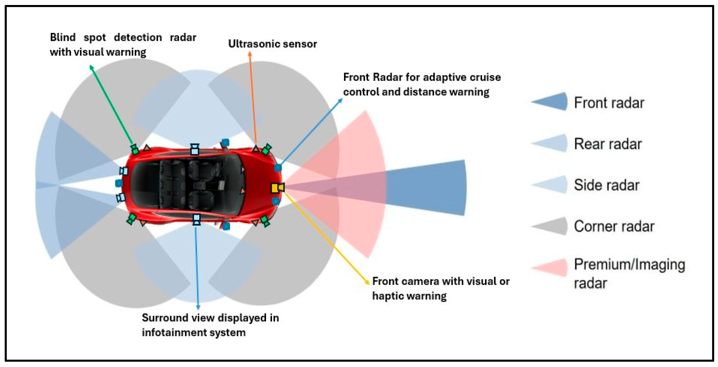
Figure 1. Automotive radar sensor layout and functions in ADAS.
Technologies 13 00555 g001
Figure 2. Geometry of the proposed ADAS antenna: (a) top view, (b) bottom view.
Technologies 13 00555 g002
Figure 3. Simulated reflection coefficients for ADAS radar.
Technologies 13 00555 g003
Figure 4. The tapered transition between the microstrip line and the antenna structure.
Technologies 13 00555 g004
Figure 5. Input impedance versus frequency at the feed plane: rin (red) and xin (blue). The resonance minimum aligns with the |S11| anchors, confirming proper matching.
Technologies 13 00555 g005
Figure 6. Simulated reflection coefficient S11: sweep of shorting-pin spacings, along with a reference case without shorting pins.
Technologies 13 00555 g006
Figure 7. Driven electric-field distribution |E| at 77 GHz illustrating the effect of the shorting pins: (a) without pins, (b) with pins.
Technologies 13 00555 g007
Figure 8. Simulated efficiency (%) and realized gain at theta = 90, phi = 0 (dBi) of the proposed ADAS antenna.
Technologies 13 00555 g008
Figure 9. Normalized total field | E | (dB) in IEEE spherical coordinates. (a) ϕ = 0 ° cut (θ-plane) at 77 GHz; (b) ϕ = 0 ° cut at 79 GHz; (c) θ = 90 ° cut (φ-plane) at 77 GHz; (d) θ = 90 ° cut at 79 GHz. (e) The vertical reference marks the end-fire direction. All curves are normalized to their respective peaks (0 dB).
Technologies 13 00555 g009
Figure 10. Fabricated antenna and measurement setups: (a) top view; (b) backside ground plane; (c) S-parameter measurement with mm Wave VNA (de-embedded WR-12 launcher/cables); (d) anechoic-chamber far-field setup using the comparison method with a WR-12 standard-gain horn.
Technologies 13 00555 g010
Figure 11. Measured and simulated S—parameters using MS4640B Vector Network Analyzer (Anritsu, Atsugi, Japan).
Technologies 13 00555 g011
Figure 12. Normalized total field | E | (dB) versus φ (deg) at θ = 90° for 77 GHz and 79 GHz. Curves are normalized to their peaks (0 dB). The pattern is symmetric about φ = 0°.
Technologies 13 00555 g012
Figure 13. S11 and gain vs. temperature for the proposed ADAS antenna (a): at 77 GHz; (b) at 79 GHz.
Technologies 13 00555 g013
Figure 14. Temperature-induced shifting of S11 curves (a): 77 GHz; (b) 79 GHz of the proposed antenna design.
Technologies 13 00555 g014
Figure 15. Vehicle-level antenna placement. CAD body with candidate points A–E; example 3D realized-gain (dBi) (a): for positions A (at 77 GHz), and (b) for positions D (at 79 GHz).
Technologies 13 00555 g015
Figure 16. Enhanced road safety and vehicle efficiency through ADAS and V2X Systems [48].
Technologies 13 00555 g016
Figure 17. Common failures in ADAS and traffic control systems flowchart.
Technologies 13 00555 g017
Table 1. Antenna specifications for ADAS (77–79 GHz) versus achieved performance of the proposed design.
ParameterADAS Target (Spec)Achieved 77 GHzAchieved 79 GHz
Operating band77–79 GHzMet (within band)Met (within band)
Input matchS11 ≤ −10 dB (VSWR ≤ 2) across bandS11 ≤ −10 dB; VSWR = 1.03; RL ≈ −36.6 dBS11 ≤ −10 dB; VSWR = 1.12; RL ≈ −25 dB
Realized gain (end fire)≥9.5 dBi @77 GHz; ≥10.5 dBi @79 GHz9.9 dBi11.2 dBi
Radiation efficiency (sim.)≥75% over band≈85%≈79.7%
Main lobe pointing θmaxθmax ≤ 5° (end fire θ = 90°)+3° (φ = 0°), +2° (φ = 90°)+2° (φ = 0°), +1° (φ = 90°)
3 dB beamwidth15–38°15.8° (φ = 0°), 13.8° (φ = 90°)14.6° (φ = 0°), 14.7° (φ = 90°)
First sidelobe level (SLL)φ = 0° (≈≤−10 dB)
θ = 90° (≈≤−10 dB)
−9.3 dB (φ = 0°), −9.1 dB (θ = 90°)−8.5 dB (φ = 0°), −9.4 dB (θ = 90°)
PolarizationLinear directionalLinear directionalLinear directional
Ground planeContinuous, coextensive with the substrateLg × Wg = 16.5 × 22 mm2Same
Footprint (board)As compact as possibleL × W = 16.5 × 22 mm2
Table 2. Optimized dimensions of the proposed ADAS antenna.
DimensionsValue (mm)DimensionsValue (mm)
Lsub = Lg16.5Wsub = Wg22
l19.22w114.54
L23.1w24.17
L38.6w35.18
L42w40.4
dvia0.35W55.58
Table 3. Comparisons of performance with related research publications.
Ref.Antenna TypeSize mm2 f c GHz
with RL
Peak Gain (dBi)Efficiency
%
−10 dB BW (GHz; %FBW)Fabrication
[13](ME-dipole) antenna array ( 11.8 × 8.5 ) 77 GHz,
RL < −10 dBi
12.33890NRPCB
[15]Patch loaded with I-shaped elements ( 23 × 12.82 ) 79 GHz
RL < −10 dBi
10.74NR(operating range 77–81 reported)PCB
[14]SIW antenna ( 20 × 20 ) 76.5 GHz
RL < −10 dBi
18.568.72NAPCB
[36]Horn antenna ( 10.16 × 22.86 ) 77 GHz
RL < −15 dBi
12.2NRNAWR−12 waveguide
[37]Horn and slotted waveguide ( 61.67 × 9.5 ) 77 GHz,
RL < −10 dBi
17.579.4NA3D printing
[38]Wideband cavity-slotted waveguide antennaNA79 GHz
RL > −10 dBi
12.3662NAPCB
[39]Cavity-slotted waveguide, arrayableNA(76–81) GHz14.5NANAPCB
The Proposed DesignSIW-tapered MSA ( 22 × 16.5 )77, 79 GHz
RL < −10 dBi
11.585(2.6%) covers 77–79PCB
Table 4. Effect of temperature on antenna dimensions and resonance frequency.
Temperature (°C)25456585105
Patch Length (mm)23.623.60823.61623.62423.632
Patch Width (mm)1515.00515.0115.01515.02
Fr1 (GHz)77.0877.05477.02877.00176.975
Fr2 (GHz)79.0679.03679.01979.0179.08
Gain at Fr1 (dBi)109.48.78.17.5
Gain Fr2 (dBi)11.51110.6410.219.85
Disclaimer/Publisher’s Note: The statements, opinions and data contained in all publications are solely those of the individual author(s) and contributor(s) and not of MDPI and/or the editor(s). MDPI and/or the editor(s) disclaim responsibility for any injury to people or property resulting from any ideas, methods, instructions or products referred to in the content.