1. Introduction
Mechanical systems play an important role in the design and development of devices to assist people in rehabilitation processes [
1,
2,
3,
4]. These devices reduce the need for direct assistance from the physiotherapist in repetitive tasks. In the case of gait aids, their main application is in the rehabilitation of people with Spinal Cord Injury (SCI) and stroke patients. In most cases, motorized devices are more effective than traditional methods for neuromuscular rehabilitation [
5,
6,
7].
At present, it is possible to find a wide variety of exoskeletons that seek to emulate the natural movement of human gait, with the aim to improve the patient’s experience during the rehabilitation process [
8]. Within these devices we can distinguish numerous systems, which can be classified according to their degrees of freedom, the actuators, or the mechanical system used (see
Table 1).
We will start by analyzing exoskeletons with hip, knee, and ankle joints that limit motion to a plane. EksoNR [
9] is a two-legged exoskeleton connected to a structure on the torso that contains the batteries and the control computer. The device has six DOFs. Four of them are active and controlled by two motors on each leg, one on the hip and the other on the knee. The remaining two degrees of freedom correspond to the rotation of the two ankles, which are constrained with a spring in each ankle. Indego [
9] is an exoskeleton similar to the previous one, with motors on the hip and knee joints of each leg. The difference from EksoNR is that, in this case, the ankle has a passive spring-loaded joint. ReWalk [
10], like EksoNR, uses two motors per leg to move the hip and knee joints and has a passive joint with a spring in the ankle. HAL [
11] is an exoskeleton with six motor-controlled DOFs that move each of the hip, knee, and ankle joints of each leg. Phoenix [
12] only controls the hip and knee joints and keeps the ankle joint fixed. The difference is the way the joints are activated. There is a motor that acts on the hip, but on the knee, there is an electronic gauge to trigger the joint locking/unlocking actions. WalkON [
13] has three motors per leg acting on the hip, knee, and ankle joints.
All these exoskeletons use electromyography sensors, angular acceleration sensors, or force sensors to control the motion of the exoskeleton. The disadvantage of these exoskeletons is the complexity to perform the control operations necessary to walk properly and their cost. Finally, we would like to highlight an exoskeleton that does not require actuators. Zhou et al. [
14] have developed a passive exoskeleton for each leg of the patient with built-in spring mechanisms for gravity compensation. A pair of mating gears is used to convert the tension force from the built-in springs into balancing torques at the hip and knee joints in order to overcome the influence of gravity. The disadvantage in this case is that the patient needs to have minimal control of mobility in the leg joints, as the device does not actively assist flexion and extension.
Table 1.
Exoskeleton characteristics.
Table 1.
Exoskeleton characteristics.
| EXOSKELETON NAME | TOTAL DOF | MECHANISM TYPE |
|---|
| EKSONR [9] | 6 | Serial chain with active and passive joints |
| INDEGO [9] | 4 | Serial chain with active joints |
| REWALK [10] | 6 | Serial chain with active and passive joints |
| HAL [11] | 6 | Serial chain with active joints |
| PHOENIX [12] | 4 | Serial chain with active joints |
| WALKON [13 | 6 | Serial chain with active joints |
| ZHOU ET AL. [14] | 4 | Serial chain with passive joints |
| REX [15] | 10 | Serial chain with active joints |
| MINDWALKER [16] | 10 | Serial chain with active and passive joints |
| ALEX III [17] | 12 | Parallelogram mechanisms and belt drive |
| LIU ET AL. [18] | 12 | Parallelogram and four-bars mechanisms |
The exoskeletons studied so far limit leg movement to a plane, which restricts the self-balancing ability. To avoid this limitation, exoskeletons with a larger number of actuators have been developed. Rex [
15] is an exoskeleton with five linear electric actuators per leg, two of them for hip abduction–adduction and flexion–extension movements, one for the knee flexion–extension movement, and another two for ankle dorsi/plantar-flexion and inversion–eversion movements. Mindwalker [
16], however, has three actuators per leg, two of them at the hip for abduction–adduction and flexion–extension movements, another at the knee (flexion–extension), and another two passive degrees of freedom with springs, one at the hip (rotation) and the last one at the ankle (dorsi/plantar-flexion). Regarding ALEX III [
17], it has four actuators per leg acting on abduction–adduction and flexion–extension movements of the hip, flexion–extension of the knee, and dorsi/plantar-flexion of the ankle. In addition, the two legs are attached to a platform behind the patient with four more actuators that simulate the pelvis. Finally, Liu et al. [
18] use six actuators that control the three degrees of freedom of the hip, two of the ankle, and the flexion–extension motion of the knee. The difference from the three previous exoskeletons is that it uses parallelogram and four-bar mechanisms to establish joint motion. These exoskeletons with self-balancing ability have a larger number of actuators, which implies a more complicated control action to coordinate the movements and, therefore, their complexity and cost rises compared to those described above.
Other types of rehabilitation robots which do not have the ability to perform the walking process, but help to move the leg joints, have also been explored by some researchers. Hasan et al. [
19] designed a single-legged human lower extremity rehabilitation robot that performs all movements of the hip, knee, and ankle joints using eight electric actuators.
All the exoskeletons described so far have four or more degrees of freedom, requiring complex control for proper operation. Many of these exoskeletons are prototypes that have not been marketed, and those that have are not within the reach of most patients due to their high complexity and price.
One aspect that makes the device more expensive is the number of Degrees of Freedom (DOF), since each DOF requires an actuator and implies a greater complexity in the control and setting. In order to achieve a simple and economical device, in this work it was decided to use a mechanism based on a closed kinematic chain with 1 DOF. When choosing the kinematic chain, priority was given to its compactness to allow the manufacture of a walking exoskeleton that moves with the person and its ability to accurately replicate the gait of different individuals. The number of links was not considered relevant, since its influence on price is not significant.
There are already devices intended for human gait rehabilitation which use mechanisms with 1 DOF [
20,
21]. The ankle trajectory can be reproduced with a 4-bar, 6-bar, or 7-link mechanism, but the distribution of the links and their volume do not allow the design of an exoskeleton that moves with the person and require the device to be attached to a structure [
22,
23,
24]. The trajectory achieved for the ankle with the previous mechanisms is less accurate than what can be achieved with an 8-bar linkage based on Theo Jansen’s mechanism [
21]. This mechanism is also used in devices for gait rehabilitation, although, like those mentioned above, in current devices it is fixed to a structure and does not move over the ground with the individual [
25,
26].
In this work it has been decided to use a compact 8-bar mechanism that fits the person’s lower limbs with two of its links replicating the movement of the femur and tibia. This allows optimizing the gait of the exoskeleton, not from the ankle trajectory as other authors do [
22,
23,
24,
25,
26], but considering the angles of the femur and tibia when walking.
In this work it has been decided to use a compact 8-bar mechanism that fits the person’s lower limbs, with two of its bars capable of replicating the movement of the femur and tibia. The fact that the angle of these two bars coincides with the angle of the patient’s femur and tibia when walking, allows their position to be used to synthesize a mechanism with the desired gait, rather than synthesizing the mechanism with a point that follows a specific ankle trajectory as other authors do [
22,
23,
24,
25,
26]. It should be taken into account that the ankle is the last point of the kinematic chain of these mechanisms and its trajectory can be replicated with different solutions without controlling the femur and tibia movement. Taking this to the extreme, we could design a device with a point that follows the trajectory of the ankle, but with angles of the femur and tibia that produce dislocation of the knee. The approach of this work is that the ankle trajectory is the consequence of the motion of the femur and tibia. Thus, this motion will be used to perform the synthesis, and once completed, it will be verified that the trajectories of the ankle and knee are as desired.
In summary, in this work, an exoskeleton is developed to move both legs. For this purpose, an eight-bar linkage is used, limiting the number of DOF to one per leg. This implies a limitation in the range and complexity of possible movements, since the device will be able to reproduce only the gait considered in the synthesis of the mechanism, leaving as the only variable of the exoskeleton the forward speed. With the help of crutches, it is possible to slowly change direction, but if we need an exoskeleton that allows, in addition to walking along a straight line, to make sharp turns, climb stairs, or run, the proposed solution would not be valid. However, the aim of this work is to design an exoskeleton for walking, with the focus on making it as simple and affordable as possible. One of the applications could be the rehabilitation of people with spinal injury or stroke-affected patients. At present, due to the high price and complexity of current walking exoskeletons, there are still many rehabilitation centers that do not use them. One aspect that makes it difficult to amortize the large investment is that, due to the complexity of these devices, much of the time of the rehabilitation session is spent setting up the machine for the new patient [
27].
In order to replicate the patient’s gait, it is necessary to perform a dimensional synthesis of the mechanism. The results allow defining the dimensions of the exoskeleton links, thus customizing the device for each patient. This solution provides a very simple control system. This, together with the use of inexpensive materials and the manufacture of parts with a 3D printer, drastically reduces the cost of the exoskeleton, allowing access to this type of devices for a larger number of patients.
The main contributions of this work are as follows:
Design of a patient-customized exoskeleton with mechanism synthesis techniques based on evolutionary algorithms.
Use of a mechanism with 1 DOF per leg compact enough to allow the walking exoskeleton to move over the ground with the person.
Dynamic study of the patient–exoskeleton assembly.
Development and manufacture of a low-cost exoskeleton, with simple control, affordable for most patients. The cost of the prototype was less than USD 1500, compared to the price of the exoskeletons in
Table 1, which ranges from USD 14,000 to over USD 100,000. The selling price of the new device will depend on factors such as manufacturing volume, indirect costs, and profit margin, but the cost is so low that, in any case, the price will be much lower than that of exoskeletons currently available on the market.
The remainder of this paper is organized as follows. In
Section 2, the kinematic model is developed and the algorithm used for the synthesis of the mechanism needed to define the exoskeleton is presented. Next, in
Section 3, the dynamic model is performed in order to obtain the power required in the motor joint for the operation of the mechanism. In
Section 4, the CAD design, control algorithm, and manufacture of the exoskeleton are presented. Finally, the conclusions of this work are drawn in
Section 5.
2. Kinematic Modeling
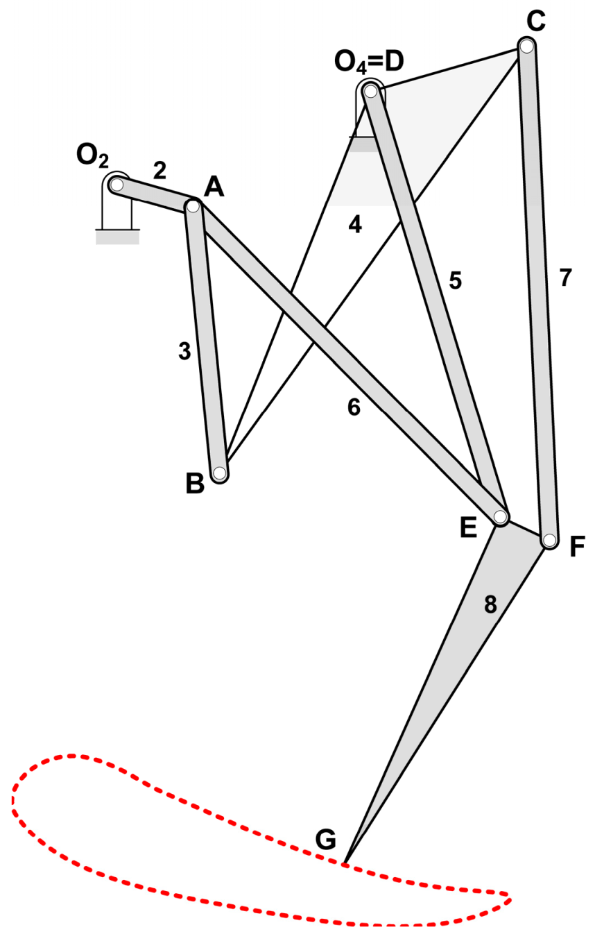
As discussed in the previous section, for the development of the exoskeleton presented in this work, an eight-bar mechanism with one degree of freedom has been used to replicate the movement of a person’s leg when walking (
Figure 1). Points
D,
E, and
G show the positions of the hip, knee, and ankle, respectively. This mechanism can be customized specifically for a person, using their femur and tibia lengths, represented in the figure by bars
L1 and
L2. Furthermore, if the ankle trajectory and the angles of the femur and tibia are obtained from a video of the person walking, a synthesis process can be carried out resulting in a mechanism whose G-point follows the recorded trajectory and at the same time the femur and tibia are placed at the measured angular positions.
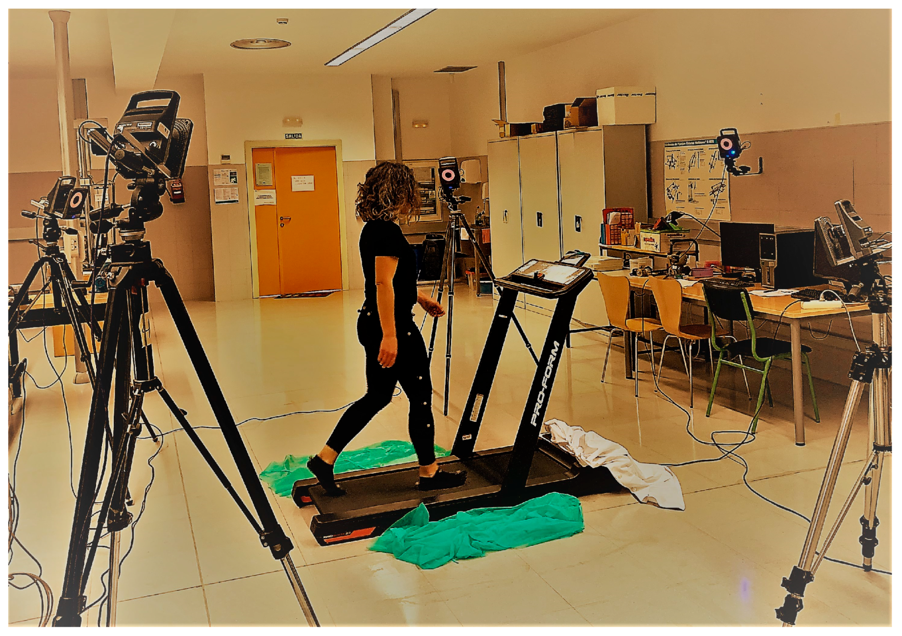
In order to study how the exoskeleton mechanism varies depending on the gait pattern and the length of the femur and tibia, measurements were taken from 52 individuals. The lengths of the femur and tibia were measured by locating the trochanter, knee, and ankle of each leg. To record the gait pattern, the trajectories of the ankle, knee, and trochanter were captured using a 3D Vicon system (Oxford Metrics
®, Oxford, UK) with five infrared cameras (
Figure 2). To this end, reflective dots were placed on the hip, knee, and ankle joints.
First, several individuals were recorded walking in both a walking corridor and on a treadmill. In this way, it was verified that their gait was very similar and it was decided to record the rest of the individuals walking on the treadmill, since this facilitates the calibration of the cameras and allows recording several steps. Next, several individuals were recorded walking on the treadmill at different speeds from 1 km/h to 3 km/h in increments of 0.5 km/h. It was observed that the ankle trajectory was very similar for all speeds, although slightly shorter at lower speeds. Considering that the operating speed of most of current exoskeletons is between 0.7 km/h and 2.9 km/h (0.2 m/s–0.8 m/s) [
28], it was decided to record the gait at a speed of 1.5 km/h (0.42 m/s) and limit the operation of the exoskeleton to this speed.
Next, all the individuals were recorded walking on the treadmill (see
Figure 2) at 1.5 km/h, and 20 measurements were taken equidistantly in time throughout each cycle. Finally, the mean of these values was calculated from four successive steps. In this way, values were obtained for the ankle (
,
) and knee (
,
) trajectories, and the femur (
) and tibia (
) angles (See
Figure 3).
Finally, the gait of the 12 individuals with the greatest difference in ankle trajectory was selected for this study, as the objective was to observe the variability in the shape of the exoskeletons optimized for different individuals.
Table 2 shows the lengths obtained for the femur and tibia for these 12 individuals and
Figure 3 shows the trajectory of the knee and the ankle.
It should be noted that the
XY coordinate system in
Figure 3 moves with the hip, while the trajectory recorded with the camera is referenced to a fixed coordinate system attached to the ground. Therefore, to compare the recorded trajectory with the one generated by the mechanism, it is necessary to transform the coordinates of the former to the
XY coordinate system of the mechanism.
Figure 3 shows the trajectories obtained for the knee and ankle with respect to this system, with the origin located at the hip (point
D). It can be seen how the trajectories of the 12 individuals change considerably.
As discussed above, in order to generate a mechanism capable of replicating the gait of a given person, a synthesis process is carried out in which the input data are the lengths of the femur and tibia, and the design variables are the parameters that define the mechanism.
Table 3 shows the input data and the design variables for the mechanism in
Figure 1.
In order to carry out the synthesis process of the mechanism for a given person, the angles of the femur and tibia along the 20 analyzed positions are considered. As will be seen below, this number is adequate to perform the synthesis in a short time while achieving good accuracy.
The trajectories of the ankle and the knee were not taken into account in the synthesis process but in the validation process of the results to check that the trajectories in the obtained mechanism replicate the measured trajectories.
Table 4 shows the measured coordinates for the knee and ankle with respect to the hip, as well as the angles of the femur
and tibia
for individual 6 in
Table 2, with femur (L
1) and tibia (L
2) lengths of 460 mm and 400 mm, respectively.
Equation (1) represents the objective function used in the synthesis process to evaluate the quality of each generated mechanism. It is based on summing the squared errors of the femur angle
and the tibia angle
[
2] along a kinematic cycle. The smaller the value of this function, the better the mechanism will replicate the gait of the person for whom the exoskeleton is being designed.
In Equation (1)
is the vector of design variables
, N is the number of positions to evaluate, subscript
d refers to the desired (measured) values, and
g to the values in the generated mechanism. To simplify the position analysis of the mechanism, it is considered that
, and subsequently it will be necessary to apply a rotation by means of the matrix defined in Equation (2) to obtain the coordinates with respect to the original system. (see
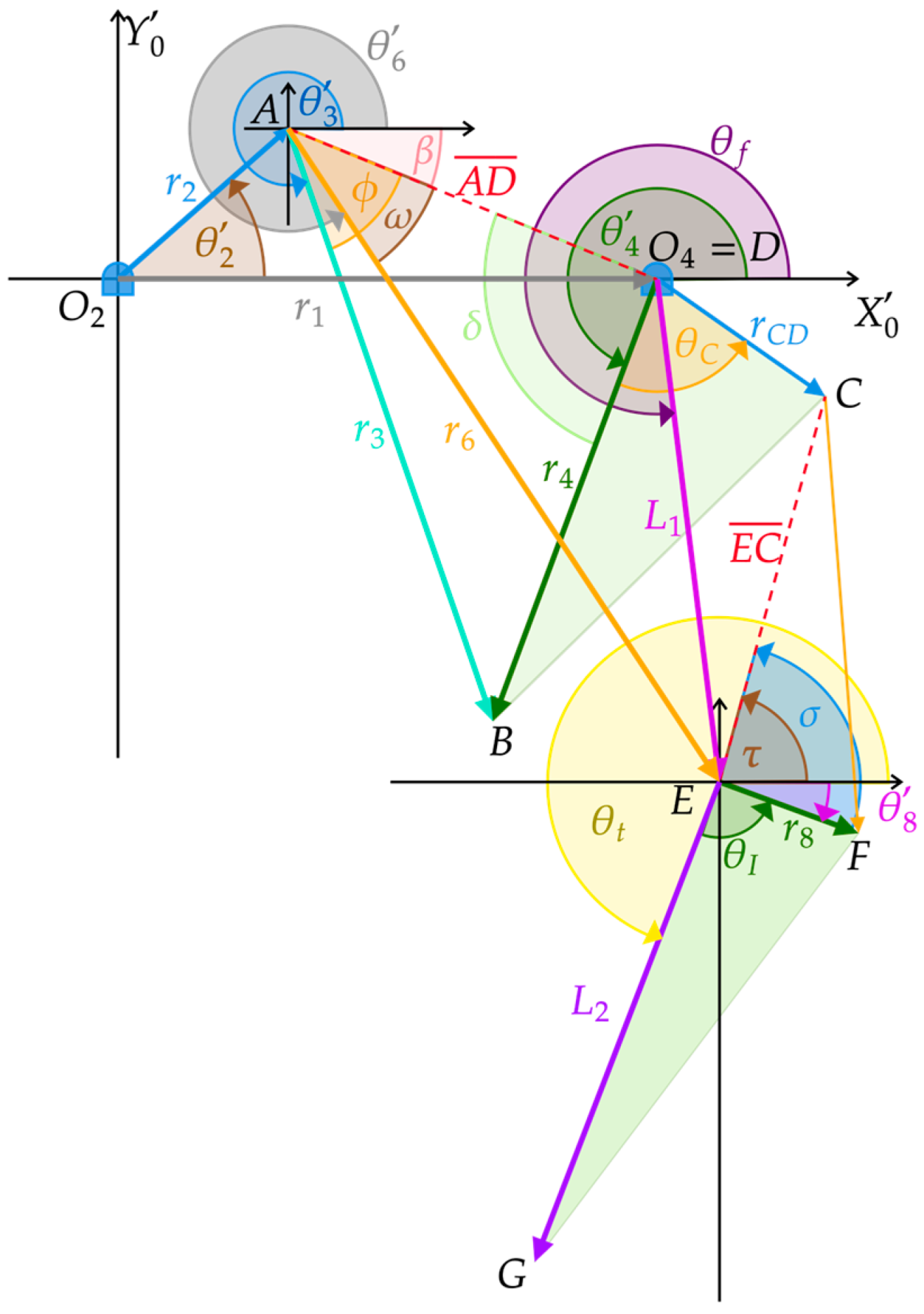
Figure 4). Therefore, the positions of the points will be calculated for an input link position of
.
Figure 4 shows that the position of point
A with respect to reference frame
is given by the Cartesian components of vector
, while the position of point D is defined by vector
, as expressed in Equation (3).
To know the position of points
B and
C (see
Figure 4) it is necessary to first calculate angles
and
by means of Equation (4).
Knowing angles
and
, the positions of points
B and
C can be obtained by vector sums of
and
, respectively, with Equation (5).
In order to calculate the Cartesian position of point
E, the value of angle
in
Figure 4 is first determined with Equation (6).
Once the value of
, has been solved, the position of point
E with respect to reference frame
is defined with Equation (7).
To calculate the coordinates of point
G in
Figure 4, it is required to know the value of angle
. For this purpose, Equation (8) is used.
Finally, the position of point
G can be determined with Equation (9).
The position values of points
A,
B,
C,
D,
E and
G have been obtained with respect to the rotated coordinate system
. Therefore, it is necessary to apply rotation matrix
to express the position with respect to the absolute coordinate system
) (see
Figure 1) as shown in Equation (10), where P represents any of the studied points.
The angles of the femur,
, and tibia,
, can easily be obtained from the positions of points
G and
E with Equations (11) and (12).
To carry out the optimization of the mechanism, the evolutionary algorithm called MUMSA (
Malaga University Mechanism Synthesis Algorithm), published by Cabrera et al. [
29], was applied. In order to solve the problem, the femur and tibia lengths, the desired ankle trajectory, and the values of angles
y
of individual 6 in
Table 4 were used as data. The used algorithm variable limits, constraints, and parameters were as follows:
As will be seen below, although the angles and lengths of the femur and tibia vary quite a lot for different individuals (see
Figure 2), it is possible to find similar solutions for all individuals. To help the algorithm to find a solution in less time and make the mechanisms for different individuals look alike, we started from very tight initial limits for the variables (see
Table 5).
The initial limits only affect the mechanisms of the first population, thus the final solution may be outside these limits. If it is desired to limit the value of the variables in the final solution, it is necessary to define constraints to reject the mechanisms that are outside the desired range. The constraints defined first limit the size of the bars so that the length of bars 1,2, 3, 4, 7 and 8 were between (see
Figure 1):
Another constraint was defined to ensure that point
, the center of the input link, was located to the left of point
(hip). This constraint is required to ensure that the exoskeleton motor can be placed on the user’s back. The position of
is defined by angle
.
Moreover, further restrictions were added to ensure that points B and E (knee) was below point A:
Finally, a further constraint was defined to ensure that the four-bar mechanism formed by bars 1, 2, 3 and 4 complied with Grashof’s rule and, therefore, the input link (bar 2) could rotate one complete turn.
The algorithm starts with the generation of an initial population consisting of
NP individuals, where each individual represents a mechanism, a possible solution to the problem. The main objective of the algorithm is to evolve this initial population towards populations in which the individuals are better, and better solutions [
29]. The reproduction process is initiated by selecting the best individual from current population
, together with two other randomly chosen individuals,
and
, to form a perturbation vector,
y
, where
F ∈[0, 2] is a value that controls the perturbation of the best individual. Next,
V is crossed with each individual in the current population,
, to generate a new individual in the next population,
. If descendant
is better than its ancestor, it replaces it. Otherwise, individual
is retained. This crossover process is carried out with a predefined probability CR ∈ [0, 1]. To further improve the solution, a mutation procedure is implemented, which consists of modifying some individual genes selectively. In our case, the genes are the design variables in
Table 3. This allows exploring possible optimal solutions in a broader scope. Mutation is performed with a defined probability MR ∈ [0, 1] with
range ∈ [−2, 2]. The algorithm runs for a predefined maximum number of iterations,
itermax, and once this limit has been reached, it concludes its execution.
Table 5 shows the values of the mechanism variables obtained after carrying out the synthesis process described above for individual 6.
Figure 5 shows the kinematic diagram of the mechanism with the values provided in
Table 6. It can be seen that, although some values are outside the limits established for the first population, the constraints are fulfilled.
Figure 6a shows the comparison between the measured and generated values of the femur angle, while
Figure 6b compares the tibia angles. It can be seen that the generated angles are very close to the measured ones.
Figure 6c,d show a comparative plot between the trajectories of the mechanism and the measured trajectories for the knee and ankle, respectively. It can also be seen that, although the optimization has been carried out considering only the angles of the femur and tibia, the trajectory generated by the mechanism for each of these points is very close to the measured one. Therefore, it can be concluded that the mechanism can replicate the gait of the individual studied in this research.
In this chapter we have developed the methodology to obtain the mechanism that replicates the gait of an individual, specifically, individual 6 in
Table 2. The mechanism obtained is compact enough to design a walking exoskeleton that moves with the person. In order to verify that the results are valid for people with different sizes and gait patterns, the synthesis of the rest of the individuals in
Table 2 has been carried out.
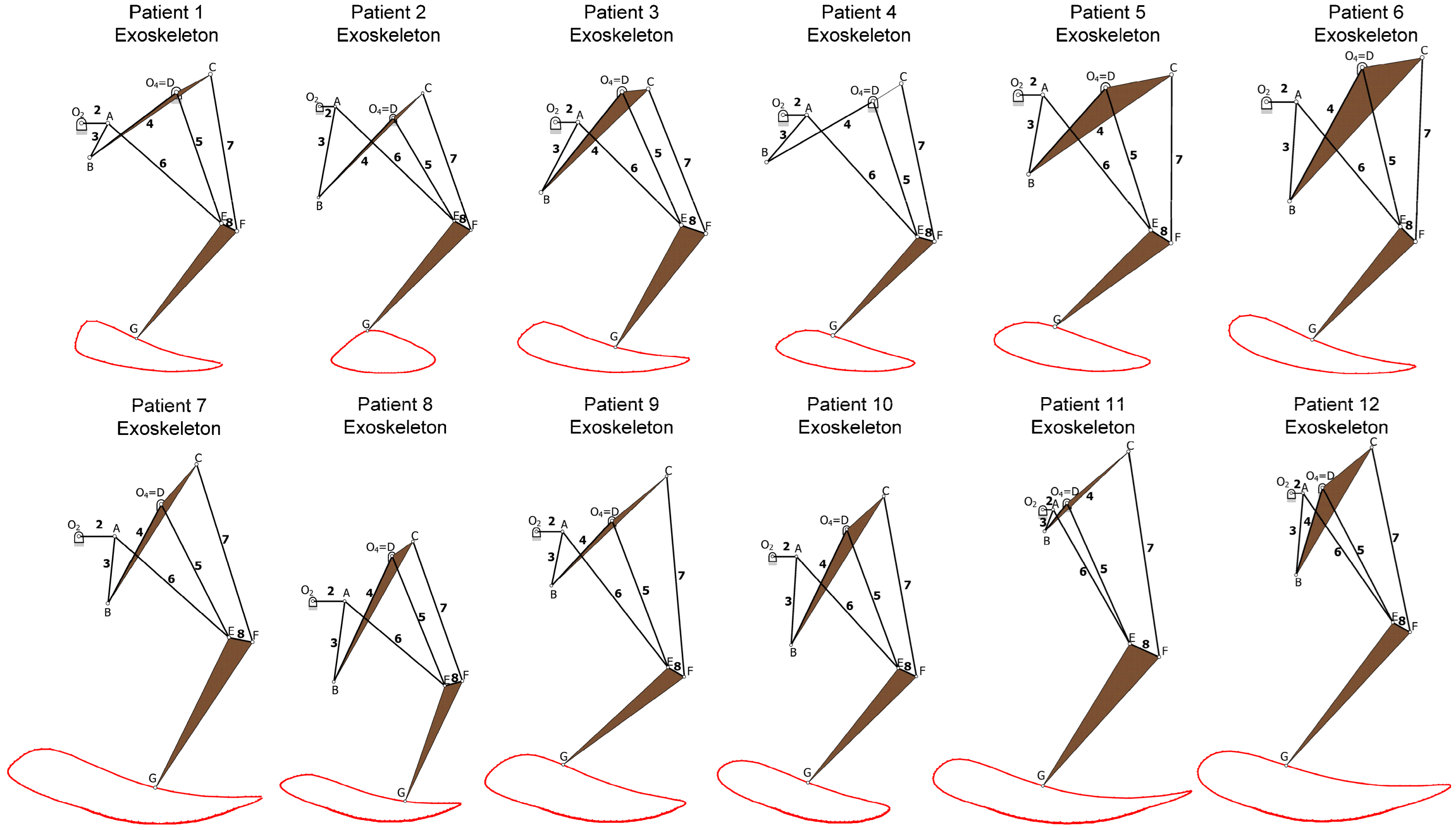
Table 7 shows the values of the mechanism variables obtained for each person.
Figure 7 represents the mechanism obtained for each of the individuals studied. It also shows the trajectory followed by the G point (ankle) in each of the exoskeletons. It should be noted that all the mechanisms obtained are similar, very compact, and allow the design of a walking exoskeleton adapted to each individual.
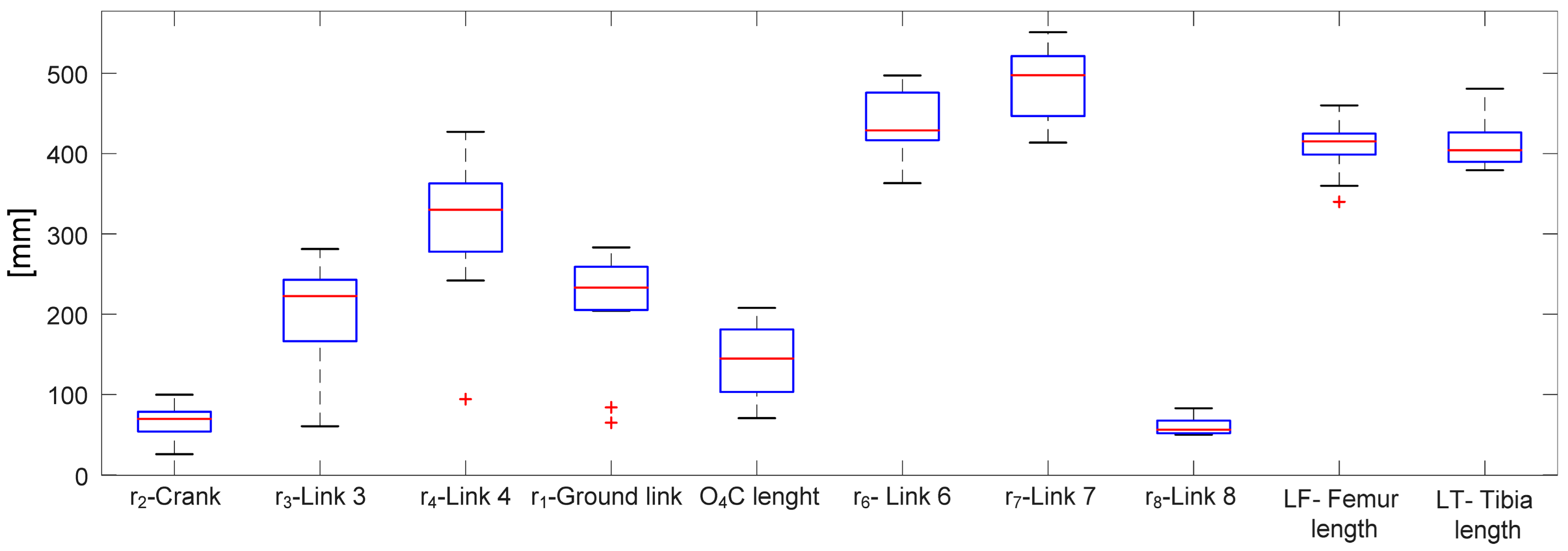
Figure 8 shows a box plot of design variables data, where the center mark in each box represents the median and the lower and upper ends of the box indicate the 25th and 75th percentiles, respectively. The whiskers are lines extending to the most extreme data points that are not considered outliers (maximum and minimum). Finally, outliers are represented individually by the ‘+’ symbol. The graph shows that the values of the mechanism design variables for the patients studied are not very different from one patient to another. This helps to quickly obtain the mechanism for a new individual by defining the limits of the initial values for the algorithm close to the median of each variable.
4. Design and Manufacture of the Exoskeleton
Figure 13a shows the CAD design of the created exoskeleton based on the results of
Table 5 and the kinematic scheme of
Figure 5. The design has been parameterized in such a way that it can be adapted to the different solutions obtained for the design variables depending on the individual, thus allowing the customization of the exoskeleton for each patient.
Figure 13b shows a front view of the device.
Figure 13c displays the exoskeleton manufactured with a combination of 3D printing technology and aluminum bars. PLA was used as the base material for the joints at the ends of the links, with 60% infill to ensure the necessary strength and durability. The links have been manufactured with aluminum bars.
Steel shafts with ball bearings have been used in the joints to reinforce this part, while minimizing friction and allowing smooth and fluid movement. The device has been assembled on a commercial orthosis in order not to start from scratch and achieve a proper connection between the mechanism and the user. In our case, a hip, knee, ankle, and foot orthosis (HKAFO) has been used. The assembly weighs 12 kg including the orthosis, motors, and batteries, which is in line with many of the walking exoskeletons currently available [
34].
One aspect to consider is the possible misalignment of the anatomical joint of the patient’s knee with the E-point of the exoskeleton. Sarkisian et al. [
35] studied the force resulting from this type of misalignment and concluded that the main component occurs in the direction of the tibial axis. The device presented in this work is attached with straps to the ankle and femur, and holds the tibia only from behind, allowing a slight movement of the knee that avoids the transmission of forces in this area.
In short, the design and manufacture of the exoskeleton has been carried out considering the customization and robustness of the device and the comfort of the user. The result is an exoskeleton suitable for rehabilitation and mobility assistance. These achievements represent a promising advance in the field of low-cost biomedical device engineering with a great potential to improve SCI patients’ quality of life. The adverse effects of prolonged wheelchair use include cardiovascular risks, fluid retention, osteoporosis, digestive complications, spinal deviation, ulcers, muscle shortening, etc. Being able to rehabilitate by standing up and walking reduces the risk of suffering from these diseases and has a positive influence on patient health [
36].
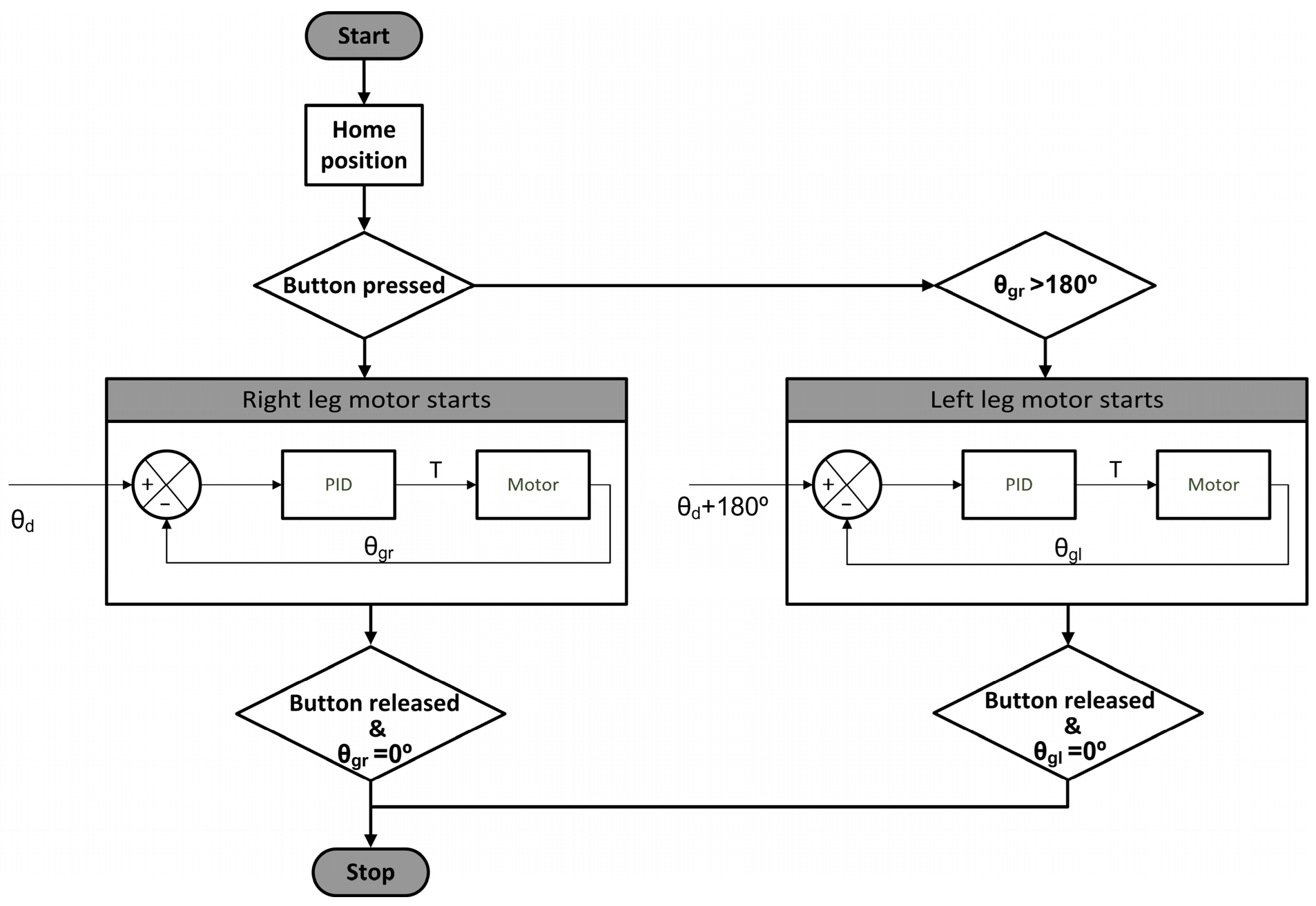
The exoskeleton is controlled by an Arduino ATMega2560 microcontroller and a motor driver BTS7960. The process begins with the calibration of the legs, which aims to place the user in a natural standing position, with one foot next to the other. Subsequently, by activating a button located on one of the crutches, the walking process starts, following the flowchart shown in
Figure 14. When the button is pressed, an angular position setpoint (
θd) is sent to the right motor by means of a sinusoidal signal and the leg starts to move. The left leg, on the other hand, replicates the movement of the right leg by maintaining a 180° dephasing. The current angular gait position (
θg) is measured using an 8192 counts-per-revolution (CPR) quadrature encoder. In order to achieve a smooth gait with constant speed, a PID controller is used to manage the torque (T) supplied by the motor. This solution for the exoskeleton control has proven to be economical, simple, and effective.
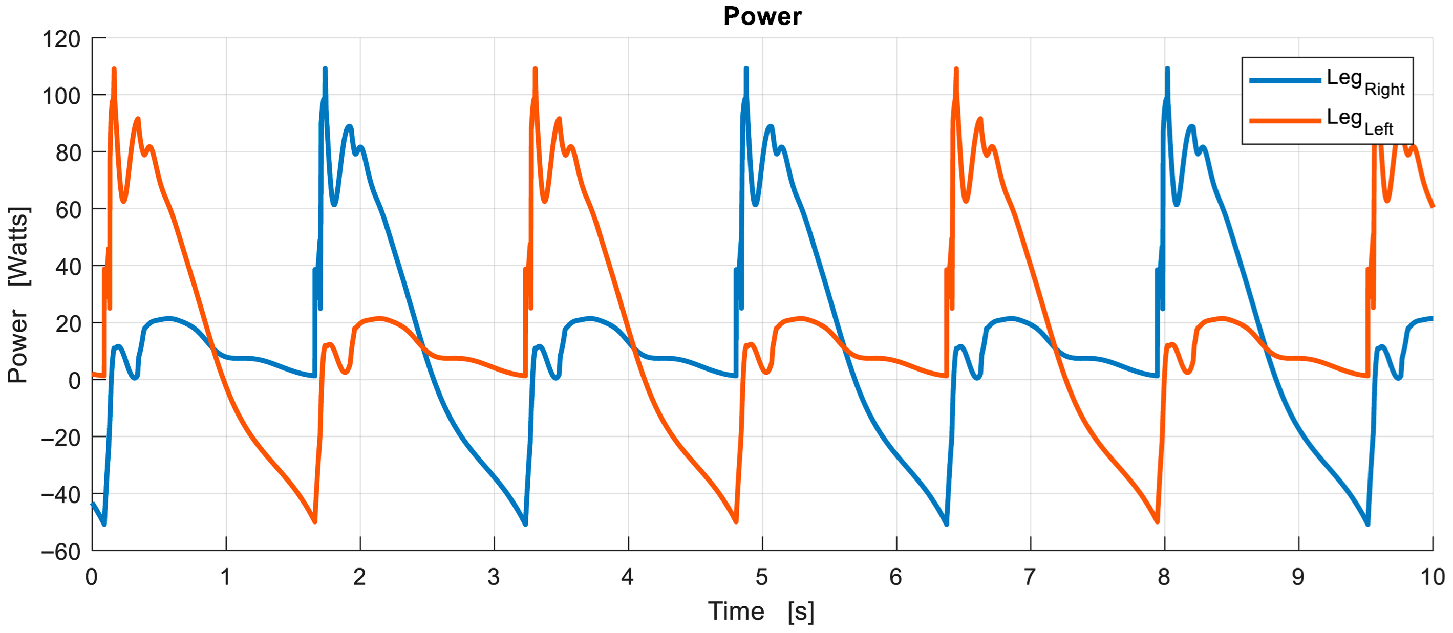
The motor driving each of the legs is a 12VDC electric motor with a maximum power output of 200 watts which has been selected to meet the power requirements of the exoskeleton shown in
Figure 11. The motor speed reduction is achieved by means of a worm gear transmission, thus ensuring smooth and reliable operation. The maximum output torque is 95 Nm.
In
Figure 15, the gait process is shown with the exoskeleton attached to the patient. Throughout the gait cycle depicted, the right leg moves from the rear to the front. The left leg starts from a forward position and ends in a backward position, maintaining an offset of 180° between the motors of the two legs at all times. In order to maintain balance, the patient uses crutches for assistance during walking. These results demonstrate the effectiveness of the exoskeleton presented in this work, confirming that its operation in real life coincides with the results obtained in the kinematic and dynamic modeling phases described in previous sections of this work.
5. Conclusions
The exoskeletons currently available to help people to walk are sophisticated and expensive. The most evolved ones have a greater number of degrees of freedom that allow them to have a greater variety of movements, even maintaining balance. However, even the simplest ones have a high cost that makes them unaffordable for patients, and in most cases, not even for many medical rehabilitation centers. This has led the authors of this work to look for an economical solution within the reach of all patients.
This paper presents an exoskeleton developed with a focus on low cost, simplicity of manufacture, and simplicity of control. To achieve these goals, an eight-link mechanism with one degree of freedom is used to control the motion of each leg. Although the topology of the mechanism can be common to all patients, the dimensions of the links have to be adapted to each individual. The application of evolutionary algorithms allows optimizing this mechanism to adapt it to the measurements of a person’s femur and tibia and, at the same time, to walk in a predefined way. This approach greatly simplifies the control of the device, since, with only one input link per leg, a predefined gait can be accurately replicated. In order to define the gait, a database of gait patterns of people of different heights and proportions can be used, or a specific gait can be defined based on the ankle trajectory and/or the desired angles of the femur and tibia throughout the cycle.
The phase offset between the cycles of the two legs during walking is 180° and remains constant throughout the gait. This suggests that a single motor connected to the two legs could be used with a 180° phase offset in the transmission. However, if it is intended to start and end the gait standing with one leg next to the other, two independent motors are necessary. Therefore, we are dealing with an exoskeleton with a single degree of freedom during walking, and two degrees of freedom in the start and stop phases.
Simulink—Simscape software 2024b was used to perform the dynamic analysis of the assembly formed by the exoskeleton and the individual. The results have allowed to select the motor necessary to move each leg, and to verify that the force required in the crutches to maintain balance has an adequate value. The walking tests performed after the fabrication of a working prototype have confirmed that the results obtained in the dynamic analysis were correct.
Creating a customized exoskeleton for each patient for use in clinical rehabilitation is a challenge. In this regard, it should be noted that the manufacture of the device includes several standard elements, such as the rear support structure, the two motors, the control unit, the battery, and the orthosis. Starting from the assembled set of standard parts, customization is very quick, as it only involves the length of the bars and their joints. In addition, if a patient no longer needs his/her device, all standard components, which are by far the most expensive, can be reused. In large rehabilitation centers, manufacturing could be carried out on site and the price of the device added to the cost of rehabilitation.

