Abstract
Three-dimensional printing has enabled the production of complex parts that are difficult to create with conventional manufacturing methods. Its additive nature has made it possible to create interconnected (assembled) parts in a single manufacturing step. This requires the development of new ways of designing, manufacturing, and testing mechanisms that do not require assembly after their creation, called non-assembly mechanisms. An approach is proposed for the design and experimental study of the properties of rotational joints created already assembled using FFF technology for 3D printing. The advantages and disadvantages of different 3D printing methods that can be used to obtain such assemblies are discussed. Basic principles for the design of assembled rotational joints, built without support structures, are introduced. Two examples of their application in creating functional robot models are presented. The features during production, and the advantages and disadvantages of the models are discussed. Models of directly assembled rotational joints with different clearances are studied, and an experiment is conducted based on measuring the magnitude of the current during the rotation of a link. This provides indirect results for the rolling resistance, on the basis of which the qualities of the joint are judged. The results from the experiments show that rotational joints with a diameter d = 10 [mm], created using FFF technology and PLA material, have the lowest resistance at a clearance in the range t = 0.15–0.25 [mm].
1. Introduction
3D printing has steadily entered many applications, such as modeling, education, design, etc. It is not only an accessible way to present ideas but also a fundamentally new technology that allows the creation of objects in a new way. Unlike traditional manufacturing, in which mechanisms are created by first manufacturing multiple elements and then assembling them, 3D printing is capable of creating a fully assembled mechanism. In [1], three main categories of 3D non-assembly mechanisms are distinguished depending on who is responsible for the mobility (Figure 1): (1) Geometry-based—These are mechanisms in which the functionality is obtained primarily from the shape of the contacting bodies. The mechanism retains its integrity after 3D printing and allows the realization of purposeful movements induced by an external force [2,3]; (2) Material-based—In this case, the material is primarily responsible for the functionality of the mechanism, using either a single flexible material or a flexible material combined with other (rigid) materials. In the second case, multi-material 3D printers are used [3,4]; (3) Pattern-based mechanisms—These are mechanisms whose movement is based on a variable internal structure of the body with different stiffness in different directions (different Infill) [5,6,7,8].
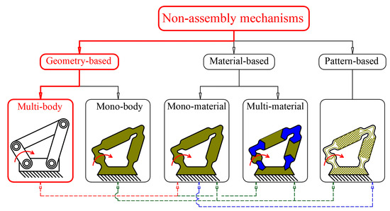
Figure 1.
Types of non-assembly mechanisms. Example with a four-link mechanism.
This division is conditional because geometry is the most important and crucial for all types of mechanisms; moreover, both single-body and multi-body mechanisms can be made of one or more materials, etc. This interconnection is shown in Figure 1 with a dashed line. Article [1] divides the first category of mechanisms into two parts: assembled mechanisms created by multiple bodies and single-body mechanisms. In this work, we focus on the first group of mechanisms created by multiple movable bodies, which are connected thanks to the geometry and made of a single material, see Figure 1—the category colored in red. The main challenges facing this type of mechanism can be systematized as follows:
The clearances between individual parts are a challenge for most 3D printing processes [9,10,11,12]. In [9], the authors investigate the design and additive manufacturing of kinematic pairs assembled by classical methods that can move relative to each other. Through empirical testing, they seek functional dependencies between force and clearance, as well as between moment and clearance. New design solutions are needed to create non-assembly mechanisms that have the appropriate shape and optimal clearances [11].
Support structures are often necessary when designing such mechanisms, as the bodies are separated from each other and cannot be printed in air without support [1,10,13]. The use of supports has undesirable side effects: their removal requires an additional post-processing step; the area above the support structures usually has a degraded surface quality; they require additional material that is often not reusable; and the support material takes additional time to manufacture. In addition, with complex geometries it can become difficult to create sufficient access space to remove the support material. Therefore, to allow for the removal of the supports, the geometry must be designed to be as open as possible [14] or specific holes must be made for its removal.
Strength of the movable joint. The parts obtained with 3D printing technology do not have a uniform structure; in addition, parts with different infill are often created [15]. These production features reduce the strength properties of the models [16]. The strength is different in different directions and depends on the material; the orientation of the part on the build platform; the printing processes, such as speeds, layer height, temperature, etc. [17]. In [5,7,18,19], the influence of infill on the mechanical properties of printed objects with FFF (Fused Filament Fabrication) technology is studied. Different types of filaments have a wide range of different mechanical properties [20,21,22].
Friction in the joint and deviations from the shape. The contacting surfaces of the joints obtained with 3D printing have a grooved structure due to the layered production of the objects. This increases the friction in such assemblies. Detailed tribological behavior of PLA (polylactic acid) is discussed in [23].
Reliability, durability, self-lubrication. Not enough research has been conducted yet to improve these parameters in 3D-printed joints for mechanisms [23]. In [24], a fatigue analysis of 3D-printed mechanisms is performed. New materials [25] with self-lubricating properties suitable for the realization of movable joints are emerging and are being investigated.
The ability to realize overhangs using FFF technology for 3D printing is important when realizing assembled structures. This allows the support structures to be significantly reduced and means that they do not need to be placed in the contact zones in rotational joints. Theoretical and experimental research of overhangs is considered in [26,27,28]. Different types of strategies for generating support structures and their placement are proposed in [29,30]. In many cases, when printing objects with FFF technology, support structures can be placed at a certain distance [31]. When printing a 3D object, it can have inclined sections relative to the building platform at an angle of up to 45 degrees, in which its shape does not change significantly [29,30]. For larger inclinations, it is recommended to place support structures. In [32], a new interesting strategy for cutting and printing overhangs without support material is proposed. This approach is based on changing the orientation of the printing nozzle in space and requires a specialized 3D printer.
The literature review shows that research is being conducted to improve the following: accuracy; the ability to realize overhangs and improve the mechanical properties of FFF 3D-printed models. These are prerequisites for increasing the spectrum of applications of 3D printing technology.
The aim of this work is to create an approach for designing non-assembly mechanisms using rotational joints without support material between the contacting surfaces, which can be manufactured with FFF 3D-printing technology. The hypothesis is investigated that with the proposed design steps, both planar and spatial functional non-assembly mechanisms can be created with a 3D printer and without the use of support structures.
The article is structured as follows: Section 2 discusses the design of rotational joints: theoretical assumptions; the difference between classical and assembled 3D-printed joints; proposes principles and methods for design, and presents an experimental setup for studying the influence of joint clearances. Section 3 presents two innovative structures (a robotic humanoid hand and a 3D-printed DELTA robot, created using the principles proposed in Section 2, as well as the results of the experiment. Section 4 contains a discussion of the creation and application of the humanoid hand, the DELTA robot, and the results of the experiment with changing joint clearances. Section 5 contains concluding remarks, and Supplementary Materials provide additional video materials and other information related to the experiments.
2. Materials and Methods
2.1. Classical Design of Rotational Joints
The rotational joint consists of two relatively rotating parts that are enclosed in such a way that their axial and radial displacement is not possible. They have one degree of freedom. These are some of the most commonly used connections between links in mechanical engineering and robotics. Such joints with sliding friction are considered, which are usually called plain bearings. According to the shape of the contacting surfaces, they are divided into cylindrical, conical, and spherical. Another division is made regarding the direction of the main load. Then, they are divided into radial and axial. Structurally (and from a topological point of view), the rotational joint can be implemented as a console (Figure 2a) or on two supports (Figure 2b).
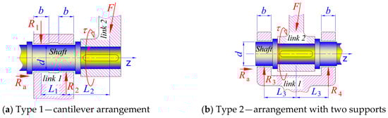
Figure 2.
Scheme for determining the support reactions of a rotational joint with a cantilever and symmetrical arrangement of the links. Here and in the other figures, the z axis is the axis of rotation. Where F—External force; τ—External torque; b—width of the plain bearing; d—diameter of the bearing; —i = 1,2,3 distances between the application points of the force vectors and the reaction forces; —axial reaction force in the plain bearing; —i = 1…n—radial reaction force in the plain bearing.
The cantilever implementation of a rotational joint allows relative rotation of the two links at any angle, even greater than 2π[rad]. While the rotational joint on two supports in most cases realizes a limited angle less than 2π[rad]. The second scheme Figure 2b, however, is more stable, takes greater forces, and has higher accuracy.
The dimensioning of classical plain bearings is usually done from a strength point of view. In specific cases of use, permissible heating or a condition for minimum permissible resistance are checked. Two main dimensions are important: the minimum diameter of the shaft and the minimum width of the bearing. There is no exact theory that would reflect all the features, and therefore the calculation of these bearings is of a conditional nature. The dependencies used are simplified by known assumptions, some of which are based on experimental data [33]. Using the scheme in Figure 2, the support reactions (for example: , и ) in the bearings are calculated. After that, the internal stresses in the shaft and its most endangered cross section are determined. The minimum diameter of the shaft can be calculated [34,35] for this cross section from the formula
where required shaft diameter for a life of N cycles; —selected design safety factor; —fatigue stress concentration factor for bending; —alternating bending moment; —steady torsional moment; —fatigue strength for a design life of N cycles (— for infinite life). When applying Equation (1), it should be noted that these coefficients must be lowered for 3D-printed parts, but , and depend on the 3D printing processes. More detailed information can be found in [34,35] or textbooks on Mechanical Design. To determine the minimum width of the bearing, it is necessary to calculate the surface pressure. Usually, a uniform distribution of the load along the length of the bearing neck is assumed, with a resultant force (see Figure 2) applied in the middle of the neck (Figure 2 and Figure 3).
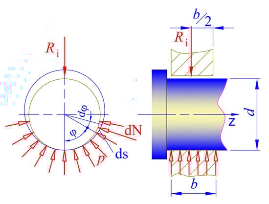
Figure 3.
Load diagram in a radial plain bearing.
The surface pressure in the contact area of the bearing can be determined by assuming a law of pressure distribution. Figure 3 shows a plain bearing, where it is assumed that the contact surface is a half-cylinder, which means that there is a clearance only in the upper half of the bearing. It is also assumed that the surface pressure is distributed uniformly. The pressure between the shaft and the sleeve, which acts on an elementary area of the bearing surface, causes a normal force . The external force , with which the bearing is loaded, is balanced by the vertical components of the elementary normal forces, i.e.,
Since , then for the force it is obtained
From the assumption of uniform pressure distribution where , expression (3) takes the form
The average pressure value determined by this equation must not exceed an allowable value for the respective shaft and bearing materials:
For practical purposes, a coefficient λ is introduced expressing the ratio between the width b of the bearing and its diameter d:
The coefficient λ is a function of the permissible surface pressure and is determined experimentally. In the case of double-sided shaft mounting (bearings at both ends), λ varies within the range . In addition to determining the main dimensions of the assembly, the design implementation requires taking measures for axial fixation to prevent displacement of elements in the direction of the axis of rotation. It should be noted that in the classical design of rotational assemblies, many objects are used, such as spacers, washers, keys and other fastening elements.
The resistive moment from friction forces in the bearing can be approximately determined by
where is the friction coefficient during sliding. Taking into account (3), we arrive at
Since the friction coefficient cannot be made smaller than a certain value, and the force is predetermined, it follows that in order to obtain a small frictional resistance moment, it is necessary for the bearing journal to have a small diameter . However, the reduction in diameter is limited by the strength conditions.
These long-known facts from engineering practice and experience need to be taken into account when designing 3D-printed assemblies.
2.2. Potential Technologies Suitable for Creating Non-Assembly Mechanisms
All 3D printing technologies can create assembled mechanisms. However, most of them require the use of support material in the joints between the moving assembly surfaces (Figure 4).
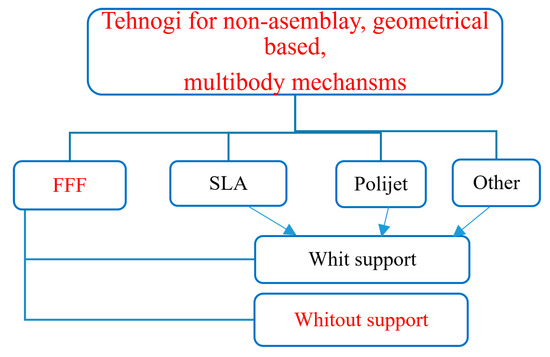
Figure 4.
Technologies that can be used to create non-assembly, geometrically based, multibody mechanisms.
Fused filament fabrication (FFF), also known as fused deposition modeling (with the trademarked acronym FDM), is a 3D printing process that uses a continuous filament of thermoplastic material. The filament is fed from a spool through a moving, heated extruder head of the printer and is deposited on the growing workpiece. The technology is the most affordable in terms of cost and production conditions. The parts are built on a horizontal platform layer by layer. Its advantages are that it can create connected objects (or mechanisms) both with supports between them and without supports. The disadvantages are mainly related to the lower accuracy compared to other technologies, deformations caused by temperature differences, and limited materials. The accuracy of this production depends on the height of the layers, which in most cases cannot be less than 0.1 [mm].
SLA (Stereolithography)—Optical Manufacturing or Resin Printing. This is a form of 3D printing technology used to create models, prototypes, templates, and production parts layer by layer using photochemical processes in which light causes chemical monomers and oligomers to crosslink to form polymers. Although stereolithography is fast and can create almost any design, it is more expensive than FFF printing. When creating connected objects with small gaps between them, resin is left behind that is difficult to remove. Our experiments with such a 3D printer show that at gaps smaller than 0.4 [mm], resin remains in them, which glues the two parts together and they cannot move. Typical SLA layer heights range from 25 to 100 microns, with 100 microns (0.1 mm) being a common setting for many applications.
Polyjet—PolyJet 3D printing is an advanced technology that creates precision parts using photopolymers, UV light, and inkjet heads. The process creates objects by layering resins. Drops of photopolymer are sprayed onto the build platform, then cured with UV lamps to bond the layers. Support materials are dissolved or manually removed for the finished PolyJet model. The layer height in PolyJet 3D printing is 16 microns. These printers and the materials for them are still too expensive. An experiment with such a printer also showed that removing support material from small gaps (0.3–0.4 mm) is very difficult.
Other—There are many other technologies for 3D printing even for metal parts, such as: Selective Laser Melting (SLM), Electron Beam Melting (EBM), etc. These technologies are very expensive and most of them use metal powder, which is also used as a support material. This powder remains in the clearances of the joints and is very difficult to remove. For these reasons, such technologies are not a subject of the study.
In the following chapters, we will focus on the fabrication of assembled rotational joints with FFF technology, due to the following reasons: it is cheap and accessible, allows us to create overhangs without support structures, can work with environmentally friendly materials such as PLA, and does not require additional processing.
2.3. Design and Principles for Implementing an Assembled Rotational Joint with FFF Technology
The considerations from point 2.1, which are well known for plain bearings in mechanical engineering, are only applicable to a certain extent to assemblies created with 3D printing technology. This is because the structure of the material obtained with this technology is not uniform. Therefore, it is more difficult to determine the strength properties [20,22]. However, at this stage, we take into account the recommended ratio for (Formula (6)). Also, for many cases, approximate strength calculations (Formula (1)) can be performed for the minimum diameter or they can be selected for design and technological reasons. When designing assembled rotational joints created with FFF printing technology, it is proposed to adhere to the following recommendations (principles):
2.3.1. The Axis of the Cylindrical and Conical Sections Should Be Perpendicular to the Built Tray
Due to the nature of FFF technology, which builds parts on a horizontal platform, the orientation of the rotational joint is very important. It can easily be seen that it is most favorable for the joint axis to be perpendicular to the build platform. This is preferable due to the fact that the accuracy in the build plane is higher and much more homogeneous than in the vertical direction. For example, if we print an object with a circular hole that is located with an axis parallel to the plane of the build platform, the hole will be deformed by the force of gravity.
2.3.2. 45 Degree Principle
When constructing the boundary surfaces to ensure rotation and axial fixation (not to move one link relative to the other in the axial direction) of the joint, slopes smaller than or close to are preferred (see Figure 5 and Figure 6).
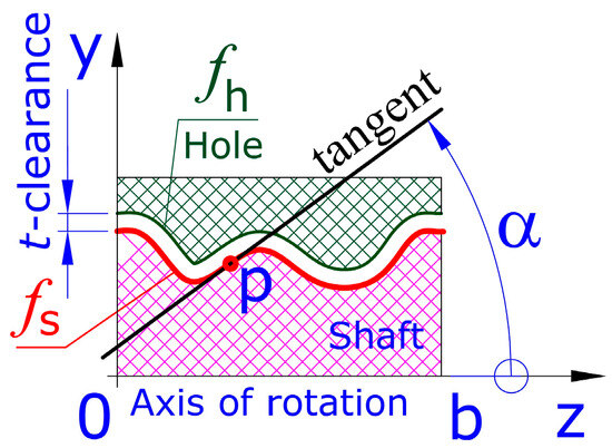
Figure 5.
Guiding curve (colored red) for a shaft and equidistant (colored green) curve of . Curve is the guiding curve for a hole in the adjacent link of the mechanism.
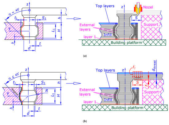
Figure 6.
Basic principles for creating assembled 3D-printed rotational joints without support structures in the bearing surfaces. (a) A joint with two conical and two cylindrical surfaces, the model on the left, and printing process on the right. The layers are greatly exaggerated to show the principle of creation. (b) A joint with one spherical and two cylindrical surfaces—model on the left and 3D print on the right.
In order to realize rotational movement of one body relative to another, it is necessary to have a section with a rotational hole in the first body, and in the second (called a link with shaft) a section with an equidistant coaxial surface of this hole. In classical production methods, cylindrical and conical surfaces are used for this purpose because they are easily manufactured with metal-cutting machines. When 3D printing is used, there is no technological limitation on the shape of the contacting surfaces. On the other hand, most 3D printers with FFF technology can realize inclinations up to relative to a vertical axis without material slipping. For these reasons, a continuous function can be used for the formation line of the rotational joint (Figure 5):
In the range , which satisfies the condition
so that the change in angle α is within the limits for the entire interval [0; b]. In other words, for each point P of the graph of the function in this interval, the tangent to the graph subtends angle α in the specified interval. Two such examples are given in Figure 6. The graph of is indicated by a solid red line.
This condition ensures that there are no areas of the joint’s forming surfaces where there is unacceptable sag caused by gravitational forces during 3D printing. Sagging can lead to the two surfaces sticking together and the inability to rotate one link relative to the other.
2.3.3. Principle of the Two Supports
Two supports should be preferred over a cantilevered nozzle overrun. When creating an assembled mechanism, there are often surfaces that need to be parallel to the build platform. Cantilever sections larger than 1 to 1.5 [mm] cannot be fabricated without the use of support structures, which effectively creates two supports again. The maximum distance S (Figure 6a) of a nozzle overrun without supports depends on the materials used and the printing processes. For materials where the elastic behavior dominates the processing time (e.g., PLA) of the layer, the material spanning the gap can be considered as a simple elastic beam (Figure 6b). The boundary constraints are the supports and the applied force per unit length required for the filament to support its own weight is estimated as [34]
where is the density of the semi-molten filament, [m] the acceleration due to gravity, —the diameter of the filament (it can be assumed to coincide with the diameter of the nozzle). Based on the theory of elastic beam deformation [34], the largest value for the deformation occurs in the middle of the distance S and is
where is the modulus of elasticity for the material, is the moment of inertia of the cross section. For a circular cross section . As the criteria for printing, an allowable central deformation can be defined. It should be noted that Formula (11) applies only to a single filament thread located on two supports. In reality, overhangs are complex structures that are determined by the direction of movement of the nozzle between the supports, the way the boundary layers are filled, and the printing parameters.
2.3.4. Minimum Clearances t in the Bearing Areas
It is necessary to minimize the clearances t in the bearing areas and to ensure larger distances in the remaining parts of the rotation surface (see Figure 6). Another important aspect is the assembly with a clearance between the bearing elements. In mechanical engineering, an assembly of the type h7/F7 is often used to implement plain bearings. This means that the clearance t for a sliding bearing with a diameter of 6 [mm] is in the order of 0.03 [mm]. At this stage of development of FFF 3D printing technologies, such accuracy and such clearances unfortunately cannot be achieved without additional post processing. For this reason, we aim to achieve the minimum possible clearance at which the two bodies can move relative to each other with minimal resistance. It is important to note that there is a difference between the design clearance and the one that is obtained after 3D printing. In addition, in practice there is no direct way to understand what the resulting clearance t is.
2.3.5. Choosing a Minimum Diameter for the Bearing
As can be seen from Formula (8), the smaller the diameter the smaller the resistive frictional moment in the bearing. Another consideration for reducing the diameter is that this usually leads to a reduction in the dimensions and cost of the mechanism. Unfortunately, in addition to the limitations mentioned in point 2.1. FFF technology has limitations caused by accuracy, which also limit .
When designing and creating a 3D model for a non-assembly mechanism for FFF printing technology, recommendations in Section 2.3.1, Section 2.3.2, Section 2.3.3, Section 2.3.4 and Section 2.3.5 are followed. For creating non-assembly mechanisms with FFF technology, the following algorithm is proposed (Figure 7):
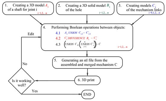
Figure 7.
Algorithm for creating a 3D-printed non-assembly mechanism.
- 1.
- A 3D model of a shaft for joint i is created together with a connecting structure . Recommendations in Section 2.3.1, Section 2.3.2, and Section 2.3.5 are used to develop the shaft, and Section 2.3.2 and Section 2.3.3 for the connecting structure. Formulas (1), (5), and (6) must also be taken into account.
- 2.
- A 3D Solid model is created for the opening . The purpose of this body is to provide sufficient clearances between the two links during their relative movement. It has a similar shape to and the condition is met. Recommendations in Section 2.3.2, Section 2.3.3 and Section 2.3.4 are useful. It is necessary to take into account the joint constraints.
- 3.
- Creating models of the links. The shape and dimensions of the links are determined by the specific mechanism and its application. In Figure 7, n + 1 is the number of links in a serial mechanism, and the number of joints is n. If the mechanism contains closed loops, the number of links and joints may be in a different ratio. Steps 1 to 3 can be performed independently of each other and in a different sequence.
- 4.
- Boolean operations between the objects created in the previous steps. These actions will lead to the creation of a mechanism. Before proceeding with them, it is necessary that all bodies are positioned and oriented relative to each other, so as to ensure future functionality of the mechanism. Before step 4.3 (see Figure 7), make sure that the links do not touch or intersect.
- 5.
- Generate stl file.
- 6.
- 3D printing. It is important how the mechanism will be positioned on the building platform, and what materials and printing processes are used.
After printing a mechanism, it is necessary to test whether it functions properly. If it turns out that some of the rotational joints do not move, corrections must be made to the model. If the clearance is too small during printing, the two elements merge and this does not allow a movable joint to be realized. It is necessary to increase the clearance. Another reason for the failure of the movable joint is sagging of overhangs on horizontal “hanging” surfaces. The editorial office must provide sufficient clearances or change the dimensions and shape of the “hanging” surfaces. The implementation of the design algorithm is illustrated in the following chapter 3 with two practical examples.
2.4. Materials and Experimental Setup
Since the mechanisms are manufactured assembled, there is no direct method for measuring roughness and inaccuracies in the shape of the printed joint. Figure 8 shows a scheme of an experimental setup for indirect measurement of the resistance in a 3D-printed assembled rotational joint. The idea is to print multiple identical joints, called here samples, for which some basic parameters are changed. The basic parameters are considered to be important dimensions such as diameter d; bearing width b; clearance t; printing processes, material, etc. In this study, we are mainly interested in the influence of clearance t on the quality of the rotational joint.
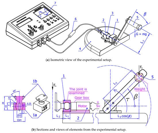
Figure 8.
Experimental setup for measuring resistance in a 3D-printed assembled rotational joint.
Sample (1) is attached to the shaft of the gear motor (2). The two components are placed together in the stand (3) attached to the base (4). The position (5) indicates an eccentrically placed weight G, which loads the specimen (1) with a variable torque T. The value of the torque T is determined by the following relationship:
where m = 0.0275 [kg] is the mass of the weight; g = 9.81 [m/s2] is the acceleration due to gravity; = 0.1 [m] is the length of the arm from the center of attachment to the weight; is the angle between the arm of the weight and the horizontal base (Figure 8b).
To carry out the experiment, a constant current gear-motor GM21 with a gear ratio i = 360:1, powered by a stabilized voltage of 5 [V] is used. The output speed without load at 6 [V] power supply is 23 [RPM], and the maximum torque of the gear-motor is 7434 [gr*cm]. As a result, the magnitude of the motor current I under load is measured—several rotations of the weight G. The data are taken using an electronic oscilloscope “Hantek—DSO-2090 USB” (7), passing through a shunt (measuring) resistance (6) with 1 [Ω]. Software for the oscilloscope “DSO-2090 USB”, that comes with it, was used. Each sample has a 3D-printed inscription, which indicates the clearance t in the bearing section b.
PLA material and Prusa MK3 printer are used and the printing processes are presented in Table 1. PLA is chosen because it is easy to work with and produces accurate shapes with small dimensional tolerances. PLA is suitable for small-sized mechanism models. It is experimented with Nylon and IGUS (special self-lubricating material) but the minimum clearances that allow movement of the joints are significantly larger. It would probably give good results with joints with large diameters. Layer height of 0.15 mm is used because it is accurate enough and not too time consuming for the printing process, as 0.1 [mm] would be, which is close to the limit of the 3D printer. The samples are printed with 85% infill, which is relatively high, but it ensures mechanical strength of the part and still it is not solid, which helps with cooling and reducing deformations. Also, according to [23] 3D printing with a 90-degree grid filling pattern with infill of 85% showed the best tribological properties in friction pairs.

Table 1.
Printing processes.
Multiple samples are created by varying the clearance t. After printing the samples, it is checked whether the elements (1a) and (1b) move relative to each other (see Figure 8b). Then the sample, which is movable, is placed in the stand (3) of the experimental setup. The power supply is turned on and the change in current is measured using the oscilloscope. The results are recorded in digital form and analyzed.
3. Results
3.1. Results of the Experiment to Study Clearances in 3D-Printed Assembled Bearings
Figure 9 shows an oscillogram of measuring the magnitude of the current as a function of time.
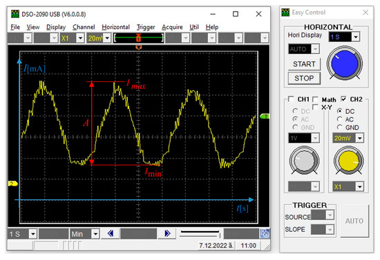
Figure 9.
Graph obtained from the oscilloscope for a sample with t = 0.2 [mm].
The graph is sinusoidal in nature, which corresponds to Formula (13). Numerous pulsations are observed, which are the result of inaccuracies in the manufacturing of the contact surfaces and disturbances in the system. For the obtained results, the following are determined: minimum current ; maximum current ; arithmetic mean value, as well as amplitude—A, for each of the samples—at different clearances and geometric shapes. The readings were made for six seconds of engine operation at an established mode.
By varying the samples’ clearance, the results for the minimum and maximum current are plotted in Table 2. At values less than 0.05 [mm], the layers stick together and the joint becomes immovable.
Table 2.
Minimum and maximum current values at different joint clearance t.
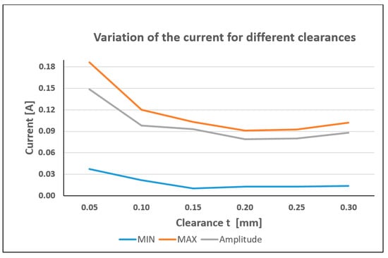
Figure 10.
Current variation at different clearances of the rotational joint.
3.2. Application of the Method for Designing Assembled Joints
The process of design and production of two mechanisms that find application in robotics is examined.
3.2.1. Prototype 1: Humanoid Hand
Using the principles of Section 2.3, a 3D-printed prototype of a humanoid hand was designed and created. The original idea is protected by a patent [35]. Each joint of the fingers is modeled in the following way (Figure 11): First, a shaft (shown in red) is modeled, which has the shape denoted by .
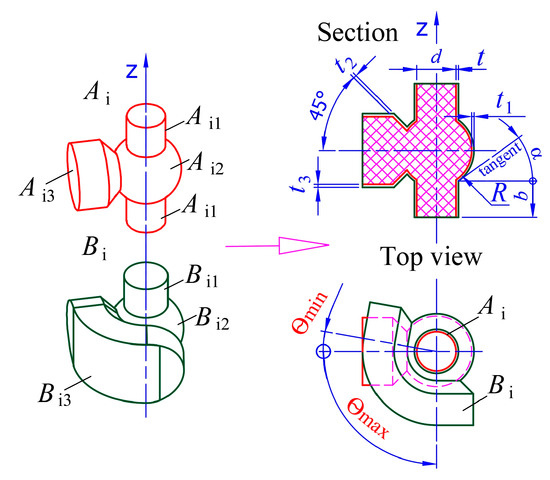
Figure 11.
Modeling the joints of a finger from a humanoid hand.
The cylindrical sections of the shaft have a diameter d = 5 [mm], and the sphere is located in the middle between them and has a radius R = 4.5 [mm]. The width of the bearing sections is b = 4.5 [mm]. The sphere is connected by a conical section to a small horizontally located cylinder . The ratio for (Formula (6)) between the diameter d and the width b of the bearing is observed. The principle 2.3.2 is observed that the tangent to the spherical section is always at an angle α less than [rad], which helps to avoid material sagging during printing. Then a solid body is modeled for the hole. It has a similar shape to but here the sections and , are increased by the necessary clearances and . Here, two approaches are possible: to model a purely rotational joint where or a rotational joint for which small spherical movements are possible at . The fingers of the human hand are complex to model. For this reason, it is possible to study both types of joints. In the variant with small spherical movements, the phalanges allow a small relative adaptation when grasping objects, similar to human fingers. Experiments are made with different clearances for and , with good results obtained at and . The section is obtained from after increasing it by and rotating the angles and according to the joint constraints of the phalanges of each finger. The joint constraints are individual for each person. The phalanges of the finger are modeled, as their lengths, shapes and sizes can be individual for different fingers (Figure 12). A base link from the finger is modeled in which the drive mechanism will be mounted.
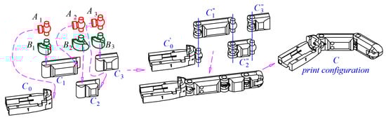
Figure 12.
Steps for modeling an assembled finger from a humanoid hand.
The shafts (colored in red) are merged with the corresponding elements : base link and phalanges of the fingers as shown in Figure 12. Links are obtained, which are not given in Figure 12. The green bodies are subtracted from the elements : phalanges , to obtain the models shown in Figure 10. Before printing the model, it is necessary that the phalanges are rotated at an angle (in this case 45 deg) relative to each other, as shown in Figure 12. on the right. This is done because if a phalanx is in an extreme position, it will touch the neighboring one, and after printing, it will merge with it. Finally, the bodies are united into one object . Figure 13 shows the printed non-assembly model of a finger. The process of printing and moving the finger can be seen in the following videos: video S1 (https://www.youtube.com/watch?v=6XNhMk1xJKU, accessed on 25 September 2025) and video S2 (https://www.youtube.com/watch?v=SOvD6ft-eT8, accessed on 25 September 2025).
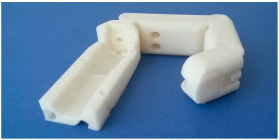
Figure 13.
Three-dimensional-printed assembled finger.
Using the proposed approach, a model of a humanoid hand made with FFF technology from PLA material is created. Figure 14 shows photographs of the hand.
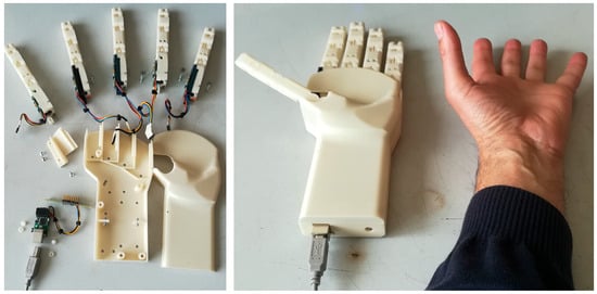
Figure 14.
Prototype of the 3D-printed humanoid hand, developed on a modular principle.
The development of the project to create the 3D-printed humanoid hand is shared on the github platform: https://github.com/prelibiton/3D-printed-humanoid-hand, accessed on 25 September 2025). From the same link, stl files for printing the fingers can be downloaded, as well as movies of the model. More details about the development, creation, functioning, control, research and application of the 3D-printed humanoid hand with assembled printed fingers can be found in articles [36,37].
3.2.2. Prototype 2: 3D-Printed DELTA Robot for Educational Purposes
Patent [38] and article [39] present a new low-cost design of a 3D-printed educational Delta robot (Figure 15, left). It consists of a base I, a fixed platform II, a movable platform III, and three identical innovative “legs” IV with rotational joints, which are manufactured assembled using FFF 3D printing technology.
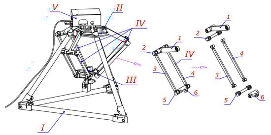
Figure 15.
The main elements of the prototype: Base I, built from tubes and 3D-printed connecting elements; Fixed triangular platform II in which three servomotors and the hardware elements of the control system are mounted; III—triangular movable platform; IV—three identical 3D-printed assembled legs; V—Control module.
Each of the “legs” IV consists of six links (1 to 6) connected by rotational joints, which form a parallelogram mechanism (Figure 15 on the right). The lengths of links 3 and 4 are the same, as well as the lengths of links 2 and 5 (Figure 16).
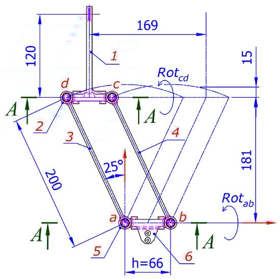
Figure 16.
Dimensions (in millimeters) and joint constraints of the parallelogram mechanism—“leg” of the DELTA robot. Section A-A is shown in Figure 17.
Each drive link 1 (Figure 15) is actuated by a servomotor mounted in the fixed base II. The basic structure of the Delta robot has 3 degrees of freedom (respectively, three servomotors) and can move objects in three-dimensional space, preserving their orientation. On the movable platform, another mechanism for changing the orientation around the vertical axis and a gripper are usually placed. The legs IV of the DELTA robot are specially designed, using the approach from point 2, so that they can be manufactured assembled with FFF 3D printing technology. The mechanism has two horizontal axes a-b and c-d, for which no joint restrictions are imposed.
The section A-A marked in Figure 16 is presented in detail in Figure 17. Each rotational joint is created in the following way (Figure 17): a vertical shaft is modeled, which has the shape marked with . The cylindrical sections of the vertical shaft have a diameter d = 12 [mm], and the two conical sections , with a slope of [rad] are located midway between them. The middle cylindrical section is connected to a small horizontally oriented cylinder . The principle Section 2.3.2 is followed. Then a body is created for the hole. It has sections and which are similar to sections and , as they are increased by the necessary clearances and .
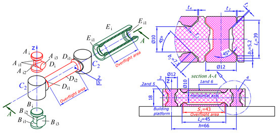
Figure 17.
Basic elements of the joints. Section A-A (see Figure 16) of the joints of a leg of the Delta robot.
Experiments are made with different clearances for and , with good results obtained at [mm] and [mm]. The part is obtained from after increasing it by 0.5 [mm] and rotating the angles and in accordance with the joint constraints of the links. The links (Figure 18) of the mechanism are modeled and their lengths are given in Figure 16. The shaft of the horizontal axes is composed of two conical sections and one cylindrical one, as shown in Figure 17. It is covered by a rotational body . The clearances between the bodies are respectively [mm] and [mm] (Figure 17).
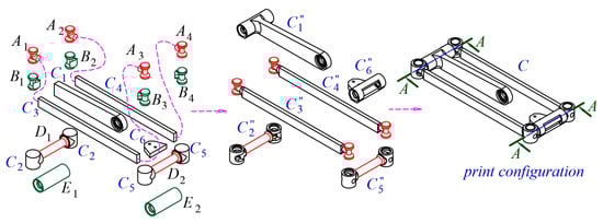
Figure 18.
Steps for modeling the leg of the DELTA robot.
Figure 18 shows the final steps for modeling the leg.
The shafts (colored in red) and are merged with their respective links . Links are obtained. The green bodies are removed from the links and to obtain the models and . The bodies and are merged, resulting in the links and . Link is obtained from the operation , and from . Finally, the bodies are merged into a single object .
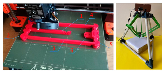
The process of printing and moving the mechanism can be seen in Figure 19 and the following videos: video S3 (https://www.youtube.com/watch?v=OJ2JAHIwl7w, accessed on 25 September 2025); video S4 (https://www.youtube.com/watch?v=EE2thTRve9U, accessed on 25 September 2025).
In [39], the mechanical design of the robot is described and a geometric method for solving the inverse kinematics problem is given. The hardware and software for controlling the robot are presented. The robot movements are demonstrated in video S5 (https://www.youtube.com/watch?v=Q5F-d3yTs4w, accessed on 25 September 2025) and S6 (https://github.com/prelibiton/3D-printed-humanoid-hand, accessed on 25 September 2025). An experiment was conducted to study the repeatability of movement along a trajectory.
4. Discussion
4.1. Discussion and Analysis of the Results of the Experiment
For the studied sample with a diameter of the rotational joint d = 10 [mm] and a width b = 3 [mm] the minimum clearance t at which it is possible to obtain reliable movement is 0.05 [mm]. The results of current measurement indirectly indicate the resistance in the rotational joint. The smallest current recorded from the minima of the sinusoidal load is at t = 0.15 [mm], from the maxima it is in the interval t = 0.2–0.25 [mm]. The smallest amplitude is obtained at t = 0.2–0.25 [mm]. The graph in Figure 10 shows that at small clearances t the resistance increases. With increasing clearance t, the resistance (current) decreases, reaching a minimum at 0.15 [mm] and then retains almost constant values. These results show that the proposed experimental setup can be successfully used for indirect assessment of the resistance in 3D-printed assembled rotational joints. The results are for PLA material and Prusa MK3 printer with the described printing processes. The obtained optimal values for the clearances t were used in the design of the robotic arm and legs of the DELTA robot.
4.2. Discussion on the Models
Two examples are presented in which assembled 3D-printed mechanisms are successfully developed and created.
The fingers of the hand have an open (serial) structure and are modeled by strictly following the algorithm in Figure 7. The joints are of type 2 (Figure 2). The criteria proposed in point 2.3 are met. When creating these models, larger clearances t can be considered useful because this improves the adaptation of the finger when in contact with a grasping object. This fact facilitates the production of fingers with FFF technology. Here, however, the diameter d of the joints is limited (for different fingers it can vary within the range [mm] and is relatively small. This requires the use of materials (e.g., PLA) that are easy to print, of a small layer height, and with low printing speeds. It is believed that with the development of 3D printing technology and the introduction of new materials in the future, a similar approach will be suitable for creating prostheses and humanoid hands in robotics.
The second example shows a significantly more complex mechanism that is built from multiple rotational joints and has a closed structure. This structure does not allow us to strictly follow the algorithm proposed in the block diagram of Figure 7. In addition, some of the axes of the joints cannot be perpendicular to the building platform. That is, for some joints, criteria Section 2.3.1 and Section 2.3.2 are not met. Larger diameters d of the bearings can be chosen so that they are convenient for printing with FFF technology. These objects can also be created with a slightly larger layer height (for example 0.2 [mm]). In order for the mechanism to have good accuracy, the clearance t must be minimal. On the other hand, since multiple rotational joints are built simultaneously, clearances that are too close to the limit of possible movement are not desirable because the accuracy of the printer is not completely homogeneous and one of the joints may not move after printing. Here, all rotational joints of the mechanism are again of type 2 (Figure 2). It is worth discussing the creation of horizontally oriented rotational joints. For them, the nozzle has to fly considerable distances without using supports. For this reason, and the parallel arrangement of the axes, part of the printed cylindrical and conical surfaces are deformed. In these areas, it is necessary to provide sufficiently large clearances for the joint to function. These mechanisms fulfill their functional purpose thanks to the limited angles of rotation of all joints and relatively low rotation speeds.
Functional experiments are conducted with the two prototypes, which do not require significant loads. The humanoid hand model has been repeatedly used for various applications, such as demonstrating sign language [40] and grasping light cylindrical and spherical objects [41], in which no mechanical failures or damage were observed. A control program is developed by training the DELTA robot. Experiments with it show good repeatability accuracy when executing a trajectory. The results are presented and discussed in [39].
4.3. Advantages and Disadvantages of the Approach for Designing Assembled Mechanisms
The assembled mechanisms created with FFF technology and the proposed approach have the following advantages:
- -
- Assembly time is saved.
- -
- Models are cheap and easy to manufacture.
- -
- Much fewer elements are used than traditionally manufactured mechanisms. There is no need to use assembly tools because there is no assembly.
- -
- There is no need to remove support structures.
- -
- It is enough to create only a 3D model; there is no need for technical documentation.
- -
- The approach allows the creation of both planar and spatial mechanisms.
- -
- In case of damage, the entire mechanism can be manufactured again and already assembled.
- -
- The approach is suitable for testing new ideas, creating models and non-responsible applications that do not require high accuracy, speed, and strength.
Disadvantages:
- -
- The materials used by FFF printers are still limited. They do not have sufficient strength, wear resistance, and other mechanical properties suitable for industrial applications.
- -
- Accuracy varies in different directions and is not high enough for some applications.
- -
- Unwanted, uneven and difficult to predict temperature deformations occur during the manufacturing process.
- -
- The clearances between the individual moving elements cannot be measured and evaluated directly.
5. Conclusions
It is presented an approach for the design and production of assembled rotational joints intended for models of mechanisms. The steps for creating 3D models and the main principles that must be taken into account in order to obtain a movable joint, without the need for support structures, during printing, are described. The approach is applicable to creating assembled models of planar and spatial mechanisms. Two examples of creating functional prototypes are presented. A method for measuring and evaluating the resistances during movement of rotational joints created already assembled with FFF printing technology is proposed. It obtains indirect results for the resistance in the joint by measuring the magnitude of the current. The results show that rotational joints with a diameter d = 10 [mm], created using FFF technology and PLA material, have the lowest resistance at a clearance t = 0.15–0.25 [mm] designed in the 3D model. The presented experimental setup can be used in the future to evaluate the influence of other parameters of the rotational joints.
In the future, research will expand to create, study, and optimize the following: other designs of assembled mechanisms; different shapes of contacting surfaces; usage of new materials; multi-material designs, etc.
3D printing technology is developing, constantly increasing its accuracy, the quality of the materials used, and its accessibility. In this sense, this research can be the basis for the development of future production of assembled mechanisms with a broader practical application.
Supplementary Materials
Video S1 (Figure 10): https://www.youtube.com/watch?v=6XNhMk1xJKU; Video S2 (Figure 10): https://www.youtube.com/watch?v=SOvD6ft-eT8; Video S3 (Figure 19): https://www.youtube.com/watch?v=OJ2JAHIwl7w; Video S4 (Figure 19): https://www.youtube.com/watch?v=EE2thTRve9U; Video S5 (Figure 19): https://www.youtube.com/watch?v=Q5F-d3yTs4w; Video S6 (Figure 19): github—https://github.com/prelibiton/3D-printed-humanoid-hand.
Author Contributions
Conceptualization, I.C.; methodology, I.C. and B.N.; software an design, B.N. and I.C.; validation, I.C. and S.Y.; formal analysis, I.C., S.Y. and B.N.; investigation, I.C. and B.N., resources, I.C. and S.Y.; data curation, I.C. and B.N.; writing—original draft preparation, I.C., B.N. and S.Y.; writing—review and editing, I.C. and S.Y.; visualization, I.C.; supervision, I.C.; project administration, I.C.; funding acquisition, I.C. All authors have read and agreed to the published version of the manuscript.
Funding
This research is supported by a scientific-research project № KP-06-H87/5 from 06.12.2024, “Investigation of Robots and Algorithms Working in Complex Environment” with Bulgarian National Science Fund.
Institutional Review Board Statement
Not applicable.
Informed Consent Statement
Not applicable.
Data Availability Statement
The original contributions presented in this study are included in the article. Further inquiries can be directed to the corresponding authors.
Conflicts of Interest
The authors declare no conflicts of interest.
References
- Lussenburg, K.; Sakes, A.; Breedveld, P. Design of non-assembly mechanisms: A state-of-the-art review. Addit. Manuf. 2021, 39, 101846. [Google Scholar] [CrossRef]
- Cali, J.; Calian, D.; Amati, C.; Kleinberger, R.; Steed, A.; Kautz, J.; Weyrich, T. 3D-Printing of Non-Assembly, Articulated Models. ACM Trans. Graph. (TOG) 2012, 31, 130. [Google Scholar] [CrossRef]
- Megaro, V.; Zehnder, J.; Bächer, M.; Coros, S.; Gross, M.; Thomaszewski, B. A computational design tool for compliant mechanisms. ACM Trans. Graph. 2017, 36, 82. [Google Scholar] [CrossRef]
- Robert, M.; Robert, K.; Youbin, K.; Daniela, R. Printable Hydraulics: A Method for Fabricating Robots by 3D Co-Printing Solids and Liquids. In Proceedings of the International Conference on Robotics and Automation (ICRA), Stockholm, Sweden, 16–21 May 2016. [Google Scholar] [CrossRef]
- Fernandez-Vicente, M.; Calle, W.; Ferrandiz, S.; Conejero, A. Effect of Infill Parameters on Tensile Mechanical Behavior in Desktop 3D Printing. 3D Print. Addit. Manuf. 2016, 3, 183–192. [Google Scholar] [CrossRef]
- Ion, A.; Frohnhofen, J.; Wall, L.; Kovacs, R.; Alistar, M.; Lindsay, J.; Lopes, P.; Hsiang-Chen, T.; Baudisch, P. Metamaterial Mechanisms. In Proceedings of the UIST ‘16, Tokyo, Japan, 16–19 October 2016; pp. 529–539. [Google Scholar] [CrossRef]
- Alvarez, K.; Lagos, R.F.; Aizpun, M. Investigating the influence of infill percentage on the mechanical properties of fused deposition modelled ABS parts. Ing. Investig. 2016, 36, 110–116. [Google Scholar] [CrossRef]
- Kosic, B.; Dragicevic, A.; Jeli, Z.; Marinescu, G. Application of 3D Printing in the Metamaterials Designing. In Computational and Experimental Approaches in Materials Science and Engineering; Mitrovic, N., Milosevic, M., Mladenovic, G., Eds.; CNNTech 2018; Lecture Notes in Networks and Systems; Springer: Cham, Switzerland, 2020; Volume 90. [Google Scholar] [CrossRef]
- Shrey, P.; Vaibhav, S.; Rahul, R. Design for Additive Manufacturing of Kinematic Pairs. In Proceedings of the International Solid Freeform Fabrication Symposium, Austin, TX, USA, 4–6 August 2014; pp. 732–745. [Google Scholar] [CrossRef]
- Ramasubramanian, S.N.; Ramakrishna, K.; Sen, D. Design for additive manufacturing of products containing articulated mechanisms. In Proceedings of the 2nd International and 17th National Conference on Machines and Mechanisms, Bangalore, India, 16–19 December 2015; pp. 1–11. Available online: https://www.scopus.com/inward/record.uri?eid=2-s2.0-85015253494&partnerID=40&md5=2435a03a398f56399cccabdf61d0664a (accessed on 25 September 2025).
- Song, X.; Chen, Y. Joint design for 3-D printing non-assembly mechanisms. In Proceedings of the ASME 2012 International Design Engineering Technical Conferences and Computers and Information in Engineering Conference; Volume 5: 6th International Conference on Micro- and Nanosystems; 17th Design for Manufacturing and the Life Cycle Conference, Chicago, IL, USA, 12–15 August 2012; pp. 619–631. [Google Scholar] [CrossRef]
- Li, Y.; Chen, Y. Physical rigging for physical models and posable joint designs based on additive manufacturing technology. Procedia Manuf. 2017, 11, 2235–2242. [Google Scholar] [CrossRef]
- Calignano, F.; Manfredi, D.; Ambrosio, E.P.; Biamino, S.; Pavese, M.; Fino, P. Direct fabrication of joints based on direct metal laser sintering in aluminum and titanium alloys. Procedia CIRP 2014, 21, 129–132. [Google Scholar] [CrossRef]
- Cuellar, J.S.; Smit, G.; Zadpoor, A.A.; Breedveld, P. Ten guidelines for the design of non-assembly mechanisms: The case of 3D-printed prosthetic hands. Proc. Inst. Mech. Eng. Part H J. Eng. Med. 2018, 232, 962–971. [Google Scholar] [CrossRef]
- Johnson, G.A.; French, J.J. Evaluation of Infill Effect on Mechanical Properties of Consumer 3D Printing Materials. Adv. Technol. Innov. 2018, 3, 179–184. [Google Scholar]
- Catana, D.; Pop, M.A.; Brus, D.I. Comparison between the test and simulation results for PLA structures 3D printed, bending stressed. Molecules 2021, 26, 3325. [Google Scholar] [CrossRef]
- Ahmed, M.; Islam, M.R.; Vanhoose, J.; Hewavitharana, L.; Stanich, A.; Hossain, M. Comparisons of Bending Stiffness of 3D Printed Samples of Different Materials. In Proceedings of the ASME 2016 International Mechanical Engineering Congress and Exposition, Phoenix, AZ, USA, 11–17 November 2016. [Google Scholar] [CrossRef]
- Baich, L.; Manogharan, G.; Marie, H. Study of infill print design on production cost-time of 3D printed ABS parts. Int. J. Rapid Manuf. 2015, 5, 308–319. [Google Scholar] [CrossRef]
- Galeta, T.; Raos, P.; Stojšić, J.; Pakši, I. Influence of structure on mechanical properties of 3D printed objects. Procedia Eng. 2016, 149, 100–104. [Google Scholar] [CrossRef]
- Platek, P.; Rajkowski, K.; Cieplak, K.; Sarzyński, M.; Malachowski, J.; Woźniak, R.; Janiszewski, J. Deformation process of 3D printed structures made from flexible material with different values of relative density. Polymers 2020, 12, 2120. [Google Scholar] [CrossRef] [PubMed]
- Letcher, T.; Waytashek, M. Material property testing of 3D-printed specimen in PLA on an entry-level 3D printer. In Proceedings of the ASME—International Mechanical Engineering Congress and Exposition, Montreal, QC, Canada, 14–20 November 2014. [Google Scholar] [CrossRef]
- Farbman, D.; McCoy, C. Materials testing of 3D printed ABS and PLA samples to guide mechanical design. In Proceedings of the ASME—International Mechanical Engineering Congress and Exposition, Blacksburg, VA, USA, 27 June–1 July 2016. [Google Scholar] [CrossRef]
- Bohun, L.; Mierzwinski, D.; Tepla, T.; Gadek, S.; Nykiel, M.; Vasylieva, A. Tribological properties of PLA-based composites produced by 3D printing. J. Achiev. Mater. Manuf. Eng. 2025, 128, 5–17. [Google Scholar] [CrossRef]
- Brčić, M.; Kršćanski, S.; Brnić, J. Rotating bending fatigue analysis of printed specimens from assorted polymer materials. Polymers 2021, 13, 1020. [Google Scholar] [CrossRef]
- Batista, M.; Tenorio, D.; Del Sol, I.; Vazquez-Martinez, J.M. Tribological Analysis of Fused Filament Fabrication PETG Parts Coated with IGUS. Appl. Sci. 2024, 14, 7161. [Google Scholar] [CrossRef]
- Bintara, R.D.; Aminnudin, A.; Ida, Z.; Arbianto, F.R.; Prasetiyo, D. The Characteristic of Overhang Object to Material Usage on FDM 3DPrinting Technology. J. Mech. Eng. Sci. Technol. 2019, 3, 35–41. [Google Scholar]
- Donnici, G.; Ferretti, P.; Montalt, A.; Francia, D.; Liverani, A. FDM Technology: Overhangs versus Layer Height Printability Performance Correlation. In Design Tools and Methods in Industrial Engineering III; Carfagni, M., Furferi, R., Di Stefano, P., Governi, L., Gherardini, F., Eds.; ADM 2023; Lecture Notes in Mechanical Engineering; Springer: Cham, Switzerland, 2024. [Google Scholar] [CrossRef]
- Cacace, S.; Cristiani, E.; Rocchi, L. A level set based method for fixing overhangs in 3D printing. Appl. Math. Model. 2017, 44, 446–455. [Google Scholar] [CrossRef]
- Ameen, W.; Mian, S.H.; Alkhalefah, A. Design the support structures for fused deposition modeling3D printing. In Proceedings of the International Conference on Industrial Engineering and Operations Management, Riyadh, Saudi Arabia, 26–28 November 2019. [Google Scholar]
- Shen, Z.H.; Dai, N.; Li, D.W.; Wu, C.Y. Bridge support structure generation for 3D printing. In Proceedings of the International Workshop on Materials, Manufacturing Technology, Electronics and Information Science, Wuhan, China, 9–11 October 2015. [Google Scholar] [CrossRef]
- Barile, G.; Leoni, A.; Muttillo, M.; Paolucci, R.; Fazzini, G.; Pantoli, L. Fused-Deposition-Material 3D-Printing Procedure and Algorithm Avoiding Use of Any Supports. Sensors 2020, 20, 470. [Google Scholar] [CrossRef]
- Wüthrich, M.; Gubser, M.; Elspass, W.J.; Jaeger, C. A Novel Slicing Strategy to Print Overhangs without Support Material. Appl. Sci. 2021, 11, 8760. [Google Scholar] [CrossRef]
- Collins, J.A.; Busby, H.R.; Staab, G.H. Mechanical Design of Machine Elements and Machines, 2nd ed.; John Wiley & Sons: Hoboken, NJ, USA, 2010; ISBN 978-0-470-41303-6. [Google Scholar]
- Beer, F.P.; Johnston, E.R., Jr.; DeWolf, J.T.; Mazurek, D.F. Mechanics of Materials, 7th ed.; McGraw-Hill Professional: Columbus, OH, USA, 2015; ISBN 978-0-07-339823-5. [Google Scholar]
- Chavdarov, I. Robotic Humanoid Hand. Patent Application No 67070 B1, 12 June 2020. (In Bulgarian). [Google Scholar]
- Chavdarov, I.; Naydenov, B.; Nikolov, V.; Georgiev, I. Modular Design, Communication and Control Systems of a 3D-printed Humanoid Robotic Hand. J. Commun. Softw. Syst. 2024, 20, 146–156. [Google Scholar] [CrossRef]
- Nikolov, V.; Georgiev, I.; Chavdarov, I. Hardware and software of a 3D printed humanoid hand. In Proceedings of the XXXII International Scientific Conference Electronics (ET), Sozopol, Bulgaria, 13–15 September 2023; pp. 1–6. [Google Scholar] [CrossRef]
- Chavdarov, I. 3D Printed DELTA Robot. Patent Application No 67733 B1, 23 May 2025. (In Bulgarian). [Google Scholar]
- Chavdarov, I.; Yovchev, K.; Naydenov, B.; Hrosinkov, V. 3D Printed DELTA Robot for Educational Purposes. In Proceedings of the International Conference on Software, Telecommunications and Computer Networks (SoftCOM), Split, Croatia, 26–28 September 2024; pp. 1–6. [Google Scholar] [CrossRef]
- Georgiev, I.; Nikolov, V.; Chavdarov, I.; Naydenov, B. Grasp planning and sign language gestures with 3D printed humanoid hand. In Proceedings of the 2024 XXXIII International Scientific Conference Electronics (ET), Sozopol, Bulgaria, 17–19 September 2024; pp. 1–5. [Google Scholar] [CrossRef]
- Naydenov, B.; Chavdarov, I.; Georgiev, I.; Nikolov, V. Controlling Finger Movements of a 3D Printed Humanoid Hand to Grasp Cylindrical and Spherical Objects. In Proceedings of the 2025 International Conference on Computer Systems and Technologies (CompSysTech), Ruse, Bulgaria, 27–28 June 2025; pp. 1–6. [Google Scholar] [CrossRef]
Disclaimer/Publisher’s Note: The statements, opinions and data contained in all publications are solely those of the individual author(s) and contributor(s) and not of MDPI and/or the editor(s). MDPI and/or the editor(s) disclaim responsibility for any injury to people or property resulting from any ideas, methods, instructions or products referred to in the content. |
© 2025 by the authors. Licensee MDPI, Basel, Switzerland. This article is an open access article distributed under the terms and conditions of the Creative Commons Attribution (CC BY) license (https://creativecommons.org/licenses/by/4.0/).