1. Introduction
Global climate change has become a major concern, as technological development and progress are increasingly based on non-renewable energy sources, such as the use of fossil fuels in various energy domains, including transportation. The use of such fuels is associated with undesired environmental effects [
1]. Environmental studies have concluded that there will be major detrimental economic effects in the near future, specifically a pronounced decrease in agricultural exports due to extreme temperatures [
2], highlighting the need for immediate action to achieve a significant reduction in greenhouse gas emissions. In addition to the evolutionary directions for the economy [
3], possible solutions include space elevators based on renewable energy; however, constraints associated with tensile strength requirements as well as energy requirements in maintaining GEO (Geosynchronous Equatorial Orbit) limit the potential applicability of this concept [
4].
Research studies have analyzed additional solutions, such as the use of microwaves in various environmental concern compensation applications [
5] and in SBSP [
6], a solution being studied and discussed for its potential positive impacts on sustainable development [
7]. By using microwaves in such an infrastructure, the propagation of energetic beams may lack precision, posing a potential hazard for operators [
8], in contrast to the accurate collimation of optical systems.
Additionally, studies have concluded that further research is needed to determine the effect of microwave radiation on neurotransmitters and EMI (Electromagnetic Interference)-induced neurobehavioral dysfunction [
9]. Furthermore, the exposure of HCE-T (Human Corneal Epithelial)-derived eye cells to microwave electromagnetic radiation has shown little influence on DNA (Deoxyribonucleic Acid) strand breaks. However, the cumulative effect of continuously exposing operators to undetected microwave radiation could lead to adverse health effects [
10]. Although microwave technology has been proposed in distance energy transfer prototypes [
11], studies have found an increase in the number of reports concerning the effects of microwave radiation in various cellular and molecular systems [
12]. The previously mentioned study concluded by recommending limitations for exposing human operators to devices emitting microwave-spectrum radiation, such as mobile personal computers, mobile phones, and microwave ovens.
Therefore, the present study minimizes the GPU resources for calibrating an alt-azimuth targeting regulator used in optical energy transfer over planetary distances. As considerations for optical energy, the hypothetical accuracy improvement over astronomical distances compared to microwave radiation could minimize the effects of energy leaks on the terrestrial biosphere. Studies in the optoelectronics field have concluded that the successful correction of the secondary spectrum in SWIR (Short-Wave Infrared Radiation) may indicate a means to correct small dispersion patterns associated with infrared chromatic aberration over interplanetary distances [
13]. Alternatively, novel methods for adjusting achromatic characteristics and thermal performance were studied [
14], resulting in a solution for mobile-phone camera lenses. By adjusting chromatic aberration and thermal defocus, an SBSP satellite could aim the energetic beam more accurately at a topographic target, such as a ground-level electric vehicle charging station.
Based on the ongoing research studies for SBSP concepts such as intermediary solar energy recovery [
15], micro-wave or laser energy transmitters [
16], as well as ground-level energy suppliers [
17], the present study further analyzes rocket thruster control calibration as well as the orbital curvature compensation based on mathematical power index iterations for the controller function. The use of thruster control for a hypothetical heliocentric laser transmitter is based on the premise of future applications in optical system improvements for beam collimation, potentially applied for transmitting or receiving optical laser energy [
18].
Furthermore, by using a RIS (Reduced Instruction Set) planetary ephemerides for optimization, regulator accuracy was mainly maintained after replacing the planetary ephemerides with CIS (Complex Instruction Set) orbital positions provided by the NASA (National Aeronautics and Space Administration) JPL (Jet Propulsion Laboratory) DE (Development Ephemerides) 200 dataset [
19,
20]. The parallel operation of optimization algorithms relies on the number of CPU and GPU cores [
21]. Thus, more parallel workers could optimize a process if less RAM (Random Access Memory) resources are used. Such algorithms could benefit from restricting the preliminary optimization domain for parallel workers, as well as allowing a greater number of workers to calibrate regulator coefficients. This could lead to a higher probability of reaching a global minimum error in non-linear models [
22], such as for the presently studied targeting application.
More accurate optimization leads to better alt-azimuth targeting performance of the in-discussion solution for distance energy transfer, providing an improved optimization solution using a hypothetical RIS–CIS sequential optimization. Parallel optimization algorithms that potentially benefit from the RIS–CIS planetary ephemerides calibration procedure include the generation of correctly rounded mathematical functions [
23], the optimization of parallel computing systems based on machine learning or fuzzy logic [
24], and the previously studied PSO (Particle Swarm Optimization) algorithm [
25].
During this study, RIS orbital trajectory optimization was performed, and the results were validated using CIS orbital positions, while describing complex orbital curvature compensation using the R2021b MATLAB/Simulink development environment. Following the state of the art and introduction for the present study, the theoretical fundamentals are described in the next section.
2. Materials and Methods
Summarizing the research areas from this study, the relevant sections for theoretical research are illustrated in the block diagram shown in
Figure 1.
This application involves hypothetically transferring optical energy over astronomical distances by harvesting energy from the Sun and converting it into infrared radiation, then directing it toward a terrestrial target or intermediate points. A laser diode array emitting radiation at 808 nm would be used in side-pumping an Nd:YAG (Neodymium-Doped Yttrium Aluminum Garnet) crystal to bypass common collimation constraints in direct-diode laser beams. An elliptical trajectory, compensated by orbital precession, was defined for RIS orbital characteristics for comparison through simulation with the results obtained based on the CIS orbital trajectory of Earth. Both instruction sets were applied relative to the reference frame, then used as in-motion points to place the observer in orbit at a location on planet Earth defined by latitude, longitude, axial inclination, barycentric motion, and other aspects.
As described above, the present study simplifies several aspects of orbital dynamics, considering that the laser transmitter satellite is located at the Sun’s center, or, from a mathematical point of view, centered at the origin of the reference frame. In future research, this satellite would be located on a stationary orbit around the Sun, using also intermediary locations to facilitate the coverage of additional constraints in energy transfer, such as minimizing the closed-loop control latency due to relativity; Lagrange points were proposed for this approach, however, geostationary orbits could provide a solution as well as further possibility for refinement.
Following the preliminary description of this study, the subsequent sections provide basic information on kinematics, mathematical operations, and additional considerations for orbital dynamics.
2.1. Motion Relativity for Coordinate Frames
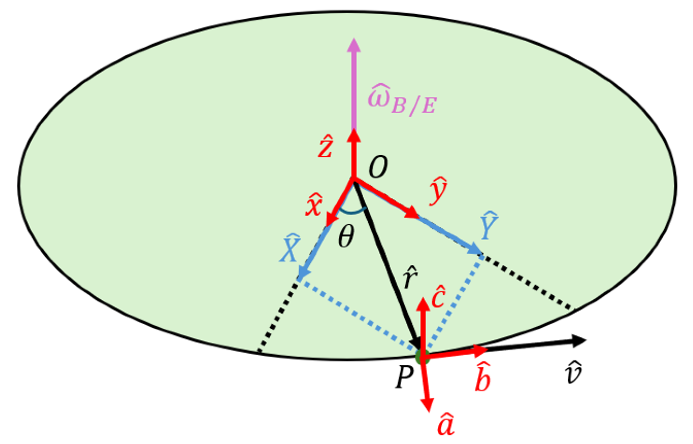
To define the observer’s perspective, multiple right-handed coordinate systems can be established based on the applied methodology or standard. For this study, an example of circular motion is illustrated in
Figure 2 below.
In this figure, unit vectors are illustrated in red, comprising two distinct orthonormal triad frames—one frame fixed at the origin and a second one fixed on the rotating object. Blue representations of vectors represent the coordinates of point “
P” in the two-dimensional reference frame. For circular motion, the body fixed frame given by Equation (1):
The body moves in relation to the reference frame from Equation (2):
with unit vector “
b” pointing in the direction of the velocity vector. The angular velocity vector is given by the transport theorem from Equation (3):
By elaborating this theorem, the angular velocity results from Equation (4):
where the angular velocity vector results as the cross product between the velocity and radius vectors. Alternatively, this factor is calculated as the rate of change for angle “
θ” in the direction of the
Z-axis (reference frame). This methodology can be further elaborated to model trajectories as a function of three coordinates, rather than two, by further deriving the example shown above.
2.2. Orientation of the Three-Dimensional Virtual Planetary System
Multiple planes can be defined to describe elliptical motion for objects around a reference point, such as around the Sun, in relation to the Sun’s orbital elements. An approximate representation of these planes applied for the Earth is illustrated in
Figure 3, where additional orientation elements are mentioned.
The direction of motion, as seen from above, relative to the illustrated reference frame, describes an anti-clockwise orbital trajectory. Various ecliptic planes can be defined for further analysis of orbital motion—the local ecliptic plane, in this case, uses the same polar orientation (north and south) as the reference frame, while the polar vectors related to the equatorial plane use the same axial offset as planet Earth. In the first case, polar vectors point to reference directions. In contrast, the equatorial plane orientation corresponds to celestial coordinates used to define the positions of various objects visible to a topographic (terrestrial) observer. A multitude of ecliptic planes can be defined; when considering the alignment of the Sun, Earth, and Moon, this results in an indefinite number of orientations.
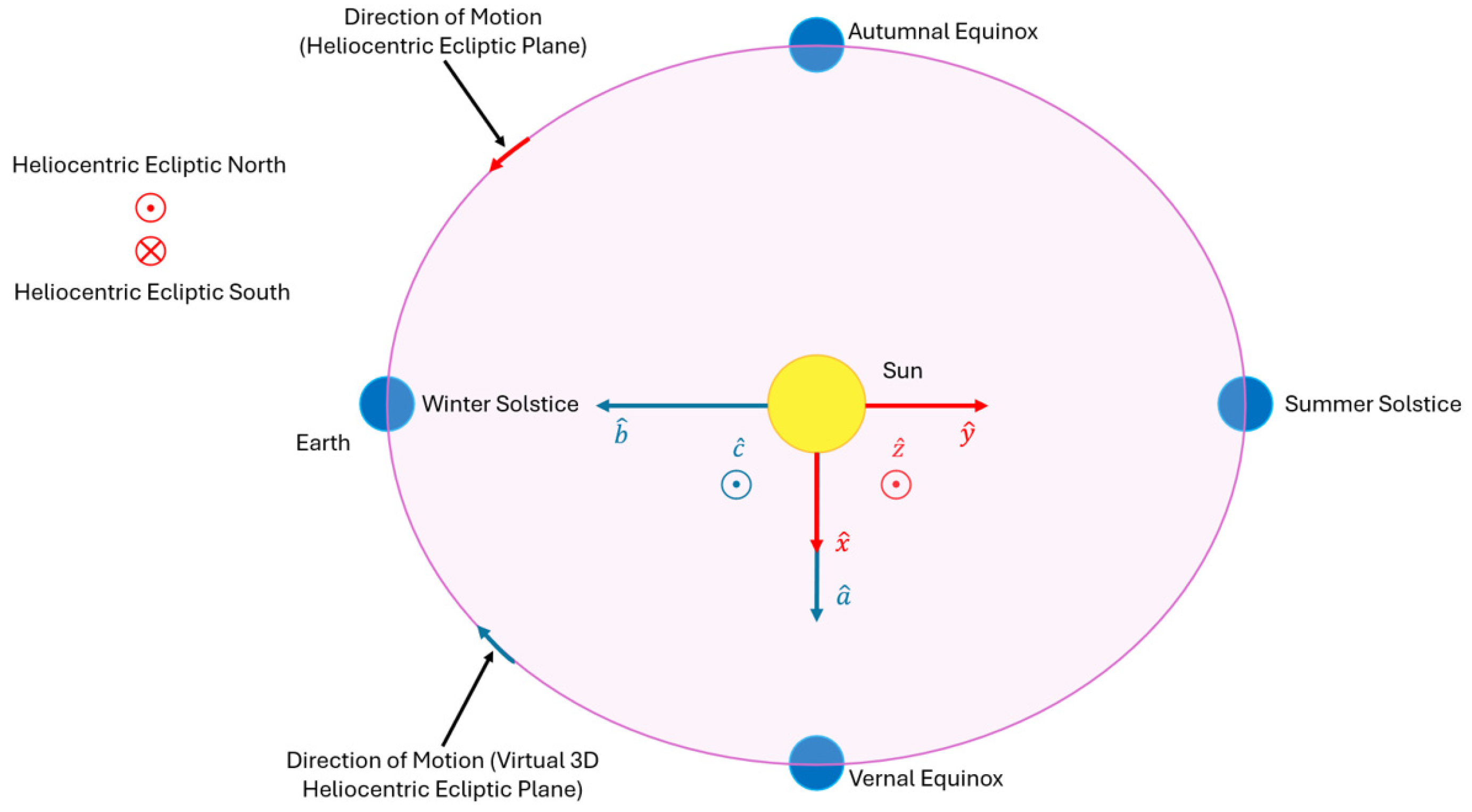
A typical orientation of planetary ephemerides applied to the Earth–Moon barycenter system involves pointing the
X-axis from the orbital frame toward the vernal equinox, as illustrated in
Figure 4 below, where a comparison between mathematical and virtual planes is described.
Some virtual environments have the left-hand rule as convention for defining the horizontal and lateral directions, as well as the vertical direction. Simple iterations, therefore, check the translation and rotation directions in the current coordinates and angles of rotation. This indicates the outcome of iterating the longitudinal angle in orbital motion and, thus, the correctness of the overall regulation.
The mathematical unit vector triad is represented in red, while for a hypothetical virtual plane it is illustrated in blue. Both directions of motion are illustrated, corresponding to the convention followed by the motion, as well as the convention followed by the cross product in each plane. Vectors “x” and “a” follow the convention of pointing toward the vernal equinox. As a consequence, their remaining vectors completing the orthonormal triad point toward the summer solstice for the “y” component as well as toward the winter solstice for the “b” component. Both “z” and “c” components point toward the observer and, in this case, no vector points through the reference plane, a direction denoted by heliocentric ecliptic south.
2.3. Elliptic Orbital Trajectory
The elliptic trajectory followed by a specific object can be mathematically modeled based on Kepler’s first two laws, as follows:
A consequence of the second law is the increasing orbital velocity as the object approaches the pericenter, the point nearest to the center of gravity. Using the two-body problem [
26,
27], the orbital position can be determined based on
Figure 5.
The variables presented above mean the following:
“f”—True anomaly, meaning the actual angle of longitude in orbit;
“E”—Eccentric anomaly;
“r”—Variable distance between orbiting object and reference point;
“v”—Variable orbital velocity;
“O”—Origin of ellipse;
“a”—Semimajor axis;
“b”—Semiminor axis;
Additionally, a variable with no geometric interpretation is used to link the mean anomaly to the mean orbital period, as described in Equation (5):
where all variables have the following meanings:
The eccentric anomaly “
E”, used in determining the radius of orbital position, was determined using the Danby–Burkart algorithm by solving the resulting transcendental equation [
28]. This involved calculating three derivative functions—namely, first, second, and third orders—and by neglecting higher orders due to repeated iterations, this resulted in calculating three differential factors.
For the eccentric anomaly, the initial conditions were determined by Equation (6):
where “
e” represents eccentricity. The domain of variation for variable “
k” is 0 to 1. To obtain values closer to the correct results, after settling the transient regime and reaching a steady state in eccentricity correction, this variable was assigned a value closer to 1 [
26].
To translate this motion into the three-dimensional plane, three orbital elements were used [
26,
27], as shown in
Figure 6.
The reference frame is illustrated in red while the orbital frame, representing the position of a celestial object, is represented in blue. The point of intersection between the orbital and reference frames is typically named the ascending node, while the pericenter maintains the previous definition. All variables mean the following:
“Ω”—Ascending node longitude angle;
“I”—Angle of inclination;
“ω”—Pericenter length, longitude angle.
To complete the RIS planetary ephemerides, additional transformations were defined to place planet Earth at the correct pericenter position, corresponding to real time and location data, as well as to achieve the desired orientation of the reference frame. For the RIS definition, the X-axis from the fixed, heliocentric reference frame points towards the vernal equinox. Furthermore, the definition of RIS characteristics required additional transformations besides the fundamental aspects, to correctly identify the position of pericenter and apocenter points during simulation.
2.4. Barycentric Motion and Perturbations
To further complement the custom RIS planetary ephemeris for planet Earth, the barycentric motion for an isolated system was considered, as illustrated in
Figure 7.
As shown above, the Earth-to-Moon mass ratio provides an approximate measure of the distance between the two celestial objects. The mathematical relationship applied to this case corresponds to Equation (7):
where the mean distance is given by summing the two radius values. This mean distance was further used to determine the distancing in orbit with respect to each object for the previously presented isolated system, based on the mass ratio.
The perturbations applied to the objects involved defining a non-linear, monotonic precession characteristic to describe the variation in the argument of pericenter for the Moon, as further discussed in the following sections.
2.5. The Topographic Observer
The required translations and rotations for simulating the position of a terrestrial observer—or alternatively, the position of an electric vehicle charging station receiving laser energy—apply to both RIS and CIS planetary ephemerides. The first set represents the custom-defined instructions previously discussed, while the NASA JPL DE 200 dataset is referred to as the CIS instructions for planetary positions.
Figure 8 describes the transformations required to place the observer or terrestrial target.
As a simplification, the shape of planet Earth was considered spherical. The figure above illustrates the reference frame using red vectors, except for the directions of the celestial poles. Overall, two translations are required, resulting in three orthonormal vector frames. The vector frame illustrated in black represents the shifting associated with longitude. Furthermore, the last frame, illustrated in magenta, was shifted based on Earth’s radius, longitude angle, and latitude angle.
All variables mean the following:
Point “O”—Geocenter;
Point “P”—Observer’s position;
Angle “ω”—Angle of longitude;
Angle “Φ”—Angle of latitude concerning the equator;
Angle “θ”—Angle of latitude concerning the North Pole;
Vector “r”—Earth radius vector.
All frames form orthonormal vector triads with orientation given by the right-hand rule, having Equation (8) as an example:
for describing the orientation of zenith, namely the orientation of a point in the sky directly above the observer, at a 90° angle relative to the local horizon line. The required transformations linking all frames were determined based on rotations about two axes, followed by shifting, considering the Earth’s radius, as shown in Equation (9):
moving the observer on the Earth’s surface. The radius, as previously mentioned, was considered constant. However, different variations can be included to compensate for the pole flattening or equatorial bulge. The coordinate set from the left side of this equation represents reference frame coordinates at the center of the Earth.
2.6. Heliocentric Alt-Azimuth Laser Targeting
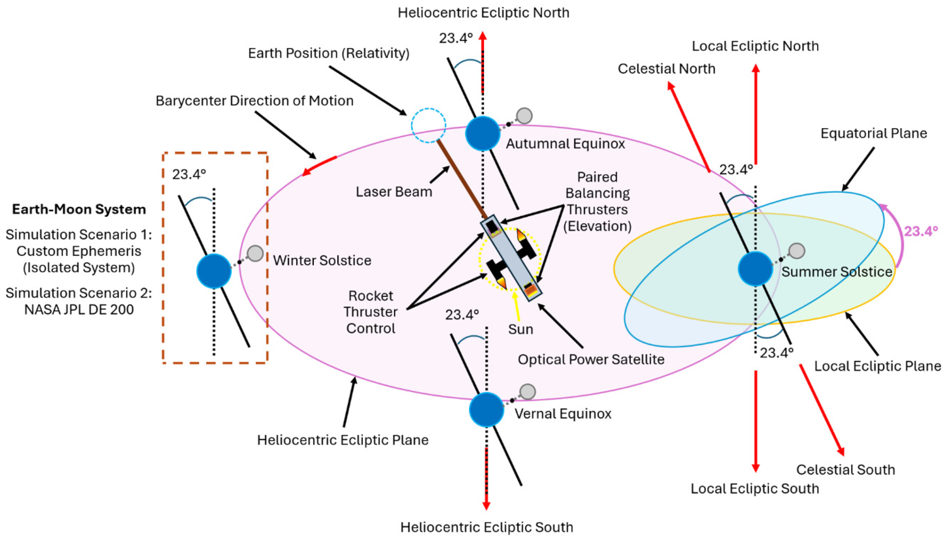
Summarizing all previously discussed aspects of orbital dynamics, the resulting hypothetical prototype is illustrated in
Figure 9.
All previous parts were summarized for concept implementation as follows:
The position of the satellite laser transmitter;
Position of the Sun describing the reference point;
The reference and orbital frames;
Motion controller type;
Axial inclination of planet Earth;
Barycentric motion of the Earth–Moon system;
Direction of motion in the reference frame, in orbit;
Orientation of axial inclination for Earth;
Position of the Earth–Moon system during the four possible events influencing daylight;
Laser beam propagation based on relativity; however, this point will not be covered in the simulation and is only used to illustrate additional constraints;
Global and local orientation definitions;
Preliminary information for simulation configuration, a part covered later.
From an open-loop perspective, the angular velocity for elevation can be defined based on Equation (10):
being the integral of angular acceleration in the applied time. The torque results as follows, based on Equation (11):
from which it is calculated based on the angular momentum of inertia
“I” and acceleration “
αElevation” for elevation motion. Equation (12) describes the dependency between angular acceleration and velocity:
which shows the resulting Laplace domain derivatives to obtain the elevation angle. Therefore, the actual elevation angle can be calculated based on Equation (13):
where two integrative operations were required. All equations for elevation control also apply to longitudinal control in a similar manner.
2.7. Definition of RIS Planetary Ephemerides
The RIS planetary ephemerides for Earth and Moon positions consists of cascading the two-body problem to determine an approximate position for these celestial objects. First, this methodology has been applied to determine the position of the Earth–Moon barycenter, using real measurements for orbital elements. The Sun was considered to be a reference point. Therefore, this object does not orbit around a barycenter. The overall reference frame is considered attached to the center of the Sun, where the satellite transmitter is hypothetically located.
This step was followed by applying the algorithm a second time, considering the objects from this barycenter isolated from all solar system perturbations. The lunar orbit was tuned for astronomical events occurring in the years 1999 and 2000, as shown in
Figure 10 below.
This part of the custom ephemerides definition was represented from 1 January 1999, 12:00:00 UTC+0, to 1 January 2001, 12:00:00 UTC+0. All dates were converted to Julian dates, with several astronomical events marked. These events were studied based on the RIS orbital characteristics and the correctness of Sun–Earth–Moon alignment results:
11 August 1999—Total solar eclipse, correctly predicted;
20 January 2000—Total lunar eclipse, correctly predicted;
1 July 2000—Partial solar eclipse, wrong alignment;
16 July 2000—Total lunar eclipse, correctly predicted;
31 July 2000—Partial solar eclipse, correctly predicted.
Summarizing the results, the calibration of RIS orbital characteristics resulted in a rough prediction precision of 80% for this study.
2.8. Miscellaneous Aspects of Orbital Dynamics
The implementation of all necessary parts for this study required analyzing various parts, such as the difference between rotation in the reference plane and orbit around the Earth.
2.8.1. Sidereal Rotations
The approximate day length, equal to 24 h with a small tolerance of tens of microseconds, is contributed to by the orbital motion in addition to the sidereal rotation of planet Earth. This former term represents the time of rotation about the planet’s axis. By subtracting the orbital contribution, the result is 23 h, 56 min, and 4 s. The current implementation utilizes sidereal time for calibration and simulation.
2.8.2. Time Zone Standards
For planet Earth, time zones define the local clock offset to a reference time, further discussed in the Results section, known as UTC (Coordinated Universal Time). Positive offsets are associated with a movement towards the east from the prime meridian (zero of longitude), such as UTC+2. In contrast, negative offsets correspond to locations on the western side of this line, such as UTC-3. By definition, UTC does not change due to DST (Daylight Saving Time).
Multiple time standards are typically used for orbital dynamics:
UTC—Universal Time Coordinated, being the local time in hours, minutes, and seconds at Greenwich, midday;
GMT—Greenwich Mean Time, being equivalent to UTC but measured from midnight;
JD—Julian Date, representing the day since 1 January 4712 BC;
TT—Terrestrial Time, defined by the International Astronomical Union for terrestrial observations taking place on Earth;
TAI—International Atomic Time, being a high-precision time standard, is calculated based on the weighted average of atomic clocks;
UT1—Universal Time, also known as solar time, is calculated based on Earth’s angle with respect to the ICRF (International Celestial Reference Frame);
TCG—Geocentric Coordinate Time, being used independently for orbital precession calculation.
However, given the multiple definitions of the available time standards, this study primarily uses UTC and JD times to present simulation results.
2.8.3. Orbital Precession and Perturbations
To define the precession and perturbation factors, orbital precession refers to a change in the orbital characteristics over time, which affects the trajectory or rotation of a celestial object from a mathematical perspective.
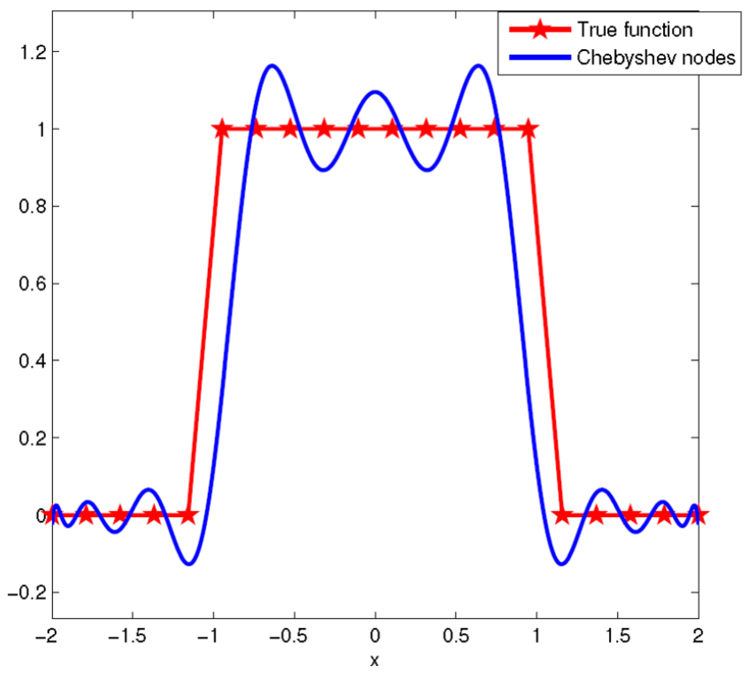
For choosing a CIS planetary ephemerides set, the NASA JPL DE 200 dataset was considered as a reference later in the simulation results. Despite being a lower-precision set compared to newer datasets such as JPL DE 441 [
29], this planetary dataset employs ad hoc approximations instead of the new Chebyshev node approximations, which present limitations similar to those in
Figure 11 [
30]. Such limitations of node approximations could increase orbital perturbations.
This figure shows the tendency of error to increase when a given function presents abrupt changes, which alters its characteristics. This case is typically encountered in simulations where a lookup table was used to provide linear interpolation, describing the observer position or terrestrial target for laser energy transmission. Due to the simulations taking place around the J2000 epoch, the DE 200 dataset was considered to provide a more accurate result, as it also offers increased regulator stability when encountering linear interpolation points that approximate the circular motion of a topographic target. The periodic oscillations at the lookup table interpolation points would be minimized when implementing various sampling rates of the orbital data.
2.8.4. Transmitter Satellite Mathematical Model
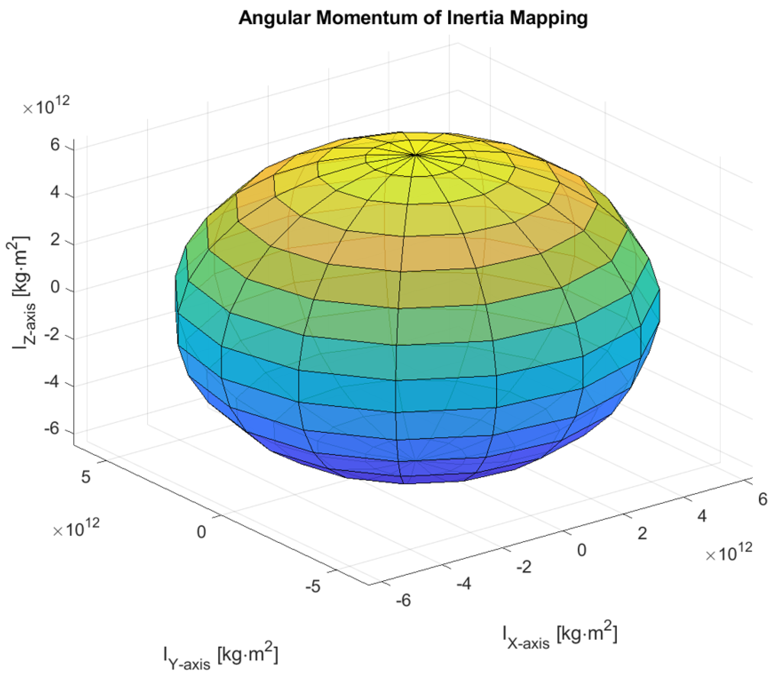
For modeling the laser transmitter located at the Sun’s center, the thruster control torque was assumed to be applied to a spherical object. Therefore, based on existing studies, the shape of the James Webb Telescope was also approximated as a sphere, simplifying the mapping of angular momentum to a spherical characteristic. For the hypothetical laser transmitter satellite, the angular momentum is described as shown in
Figure 12, indicating the same inertia for all axes of rotation.
An additional consideration, as shown above, was to enhance the mass and radius approximations based on the translation of time-domain simulations [
31]. Therefore, the approximated mass based on actual specifications [
32], representing 6500 kg, was estimated to produce the same regulation pattern at 1.6174 kilotons. The distribution of time-domain translation increased the original satellite radius, from approximately 10 m to 100 m. This translation involved configuring the mathematical model for simulating one Julian day per simulator second.
Building on the theoretical aspects previously described, the next chapter presents the simulation results for thruster control and hardware resource estimation, utilizing the RIS characteristics in parallel with heuristic optimizations.
3. Results
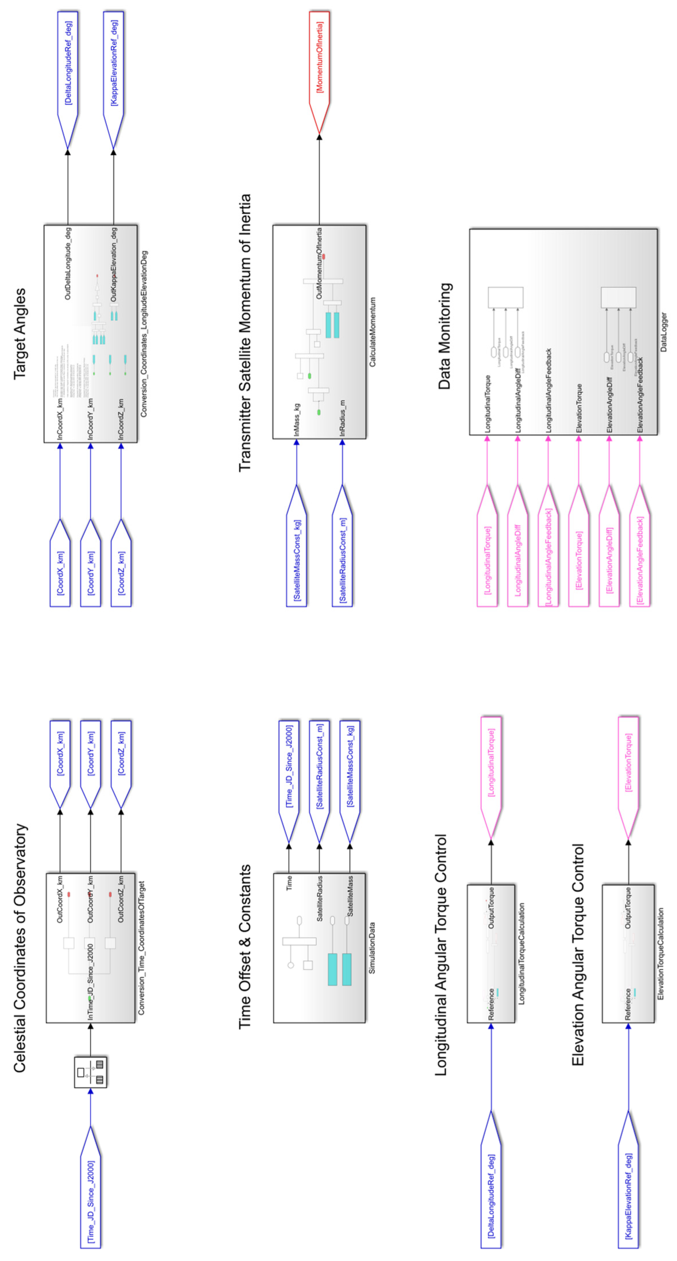
Based on all the previously described parts, namely the definition of RIS planetary ephemerides, orbital dynamics, and alt-azimuth thruster control, the mathematical model was implemented in MATLAB/Simulink, with its block diagram presented in
Figure 13 below.
This model presents the mathematical implementation of a thruster control regulator for two angles: longitudinal and elevation regulations. It covers two possible scenarios—simulation using the RIS and CIS orbital characteristics. For validating the correctness of orbital positions, the observational basis has been previously described in the alignment of the Sun, Earth, and Moon.
3.1. Orbital Curvature Compensation
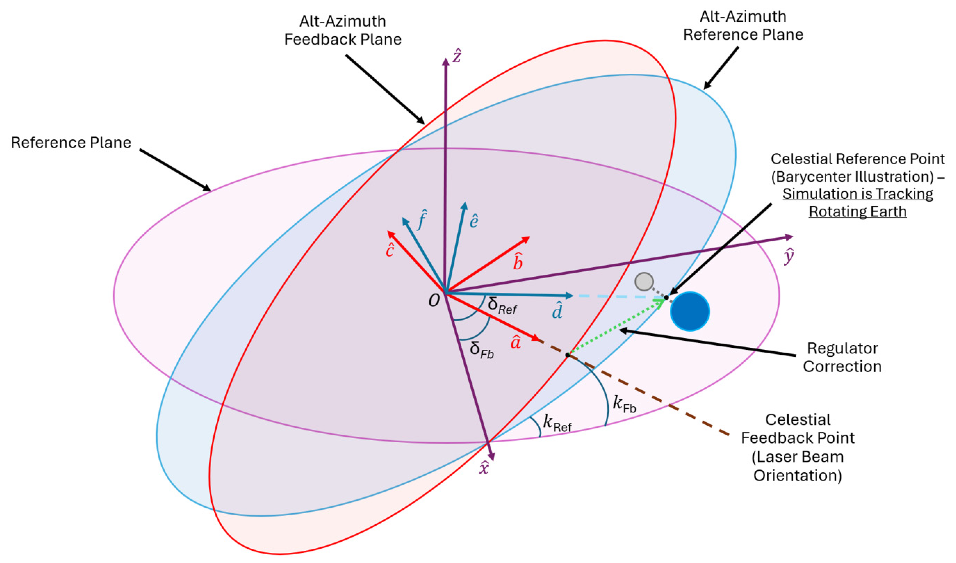
The block diagram for the alt-azimuth targeting regulator description is illustrated below in
Figure 14.
Hypothetically, the laser transmitter satellite is located at the origin of the heliocentric reference frame. This transmitter moves with respect to the reference frame, with the unit vector “a” pointing toward the feedback celestial coordinate set, which corresponds to the orientation of the laser beam. The desired beam orientation is represented in the observer reference frame (illustrated in blue by the alt-azimuth reference plane) by the unit vector “d”, which serves in the regulator function to provide thruster torque and mitigate errors in the closed-loop regime. Several annotations were described below:
“δRef”—Observer reference longitudinal angle;
“δFb”—Laser beam feedback longitudinal angle;
“kRef”—Observer reference elevation angle;
“kFb”—Laser beam feedback elevation angle.
A total of two directions of motion are possible for this hypothetical satellite, both corresponding to alt-azimuth control. The torque was considered balanced with respect to the center of mass. Therefore, the transmitter satellite remains fixed, centered on the origin of the heliocentric reference frame.
For orbital trajectory compensation in a closed loop, the mathematical power of the controller function was increased from 1 to 10. Summarizing all obtained results, the laser beam targeting accuracy characteristics are described in
Figure 15, where the charging station (or topographic observer) is considered to be located in Eastern Europe, specifically in Romania, in Cluj-Napoca.
This results in one requirement for compensating complex curvature to aim the laser beam toward a topographic target. At higher mathematical powers, the transmitter satellite is able to maintain its target—the charging station receiver position—with errors below ten millimeters, having this controller function based on PID (Proportional-Integral-Derivative) regulators.
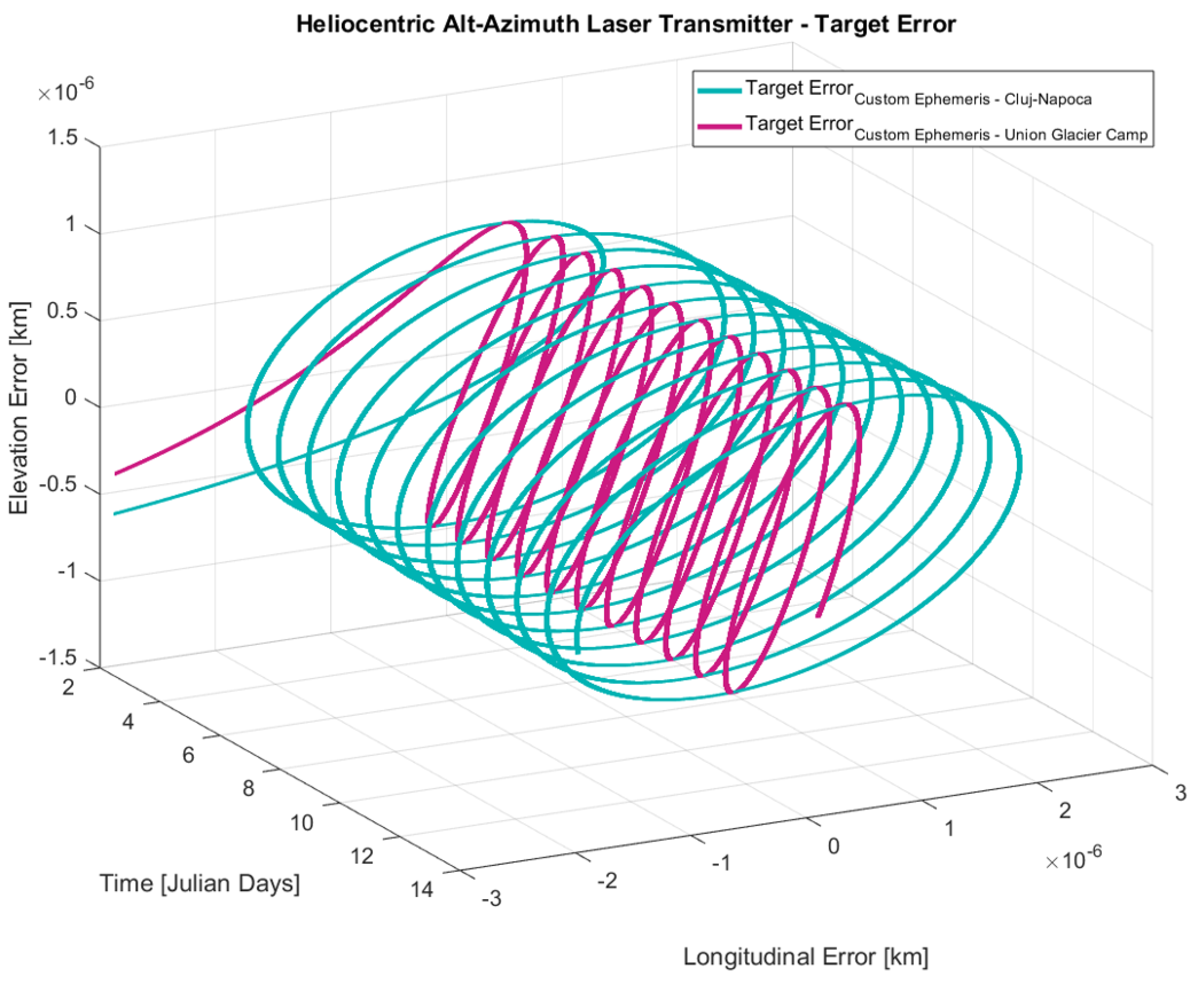
Starting from the second Julian day of simulation, and including a second location to validate this regulation, the results are illustrated in
Figure 16.
The second location represents a geographic position found in the southern hemisphere of the Earth, being much closer to the South Pole in contrast to the first mentioned location, namely Cluj-Napoca. Overall, an observer would experience a less pronounced movement from Union Glacier Camp, Antarctica, compared to Cluj-Napoca; this reduced motion relative to the reference point results in smaller longitudinal and elevation errors, validating in turn the replication of space-based solar power targeting regulation for RIS planetary ephemerides through consistent results.
3.2. Thruster Torque Regulation
The simulation results validation continues with the description of a total of four test cases, distributed across the two previously mentioned locations. All simulations start on 1 January 2000, 00:00:00 UTC+0, and end on 15 January 2000, 00:00:00 UTC+0, as described in
Table 1 below.
Each case study was described individually below, covering the results for each location using different planetary ephemerides. The coordinated time was adjusted to the local time of each location in the previous table.
3.2.1. Case Study: Charging Station in Cluj-Napoca, Romania
The position representation on the globe is illustrated in
Figure 17, for which the coordinated time was specified close to the J2000 epoch date.
As illustrated, this location constantly rotates around the Earth’s axis of rotation, with its three-dimensional position changing constantly based on the current Julian day. For this case study, the charging station is located in the northern hemisphere, as defined by its GPS coordinates.
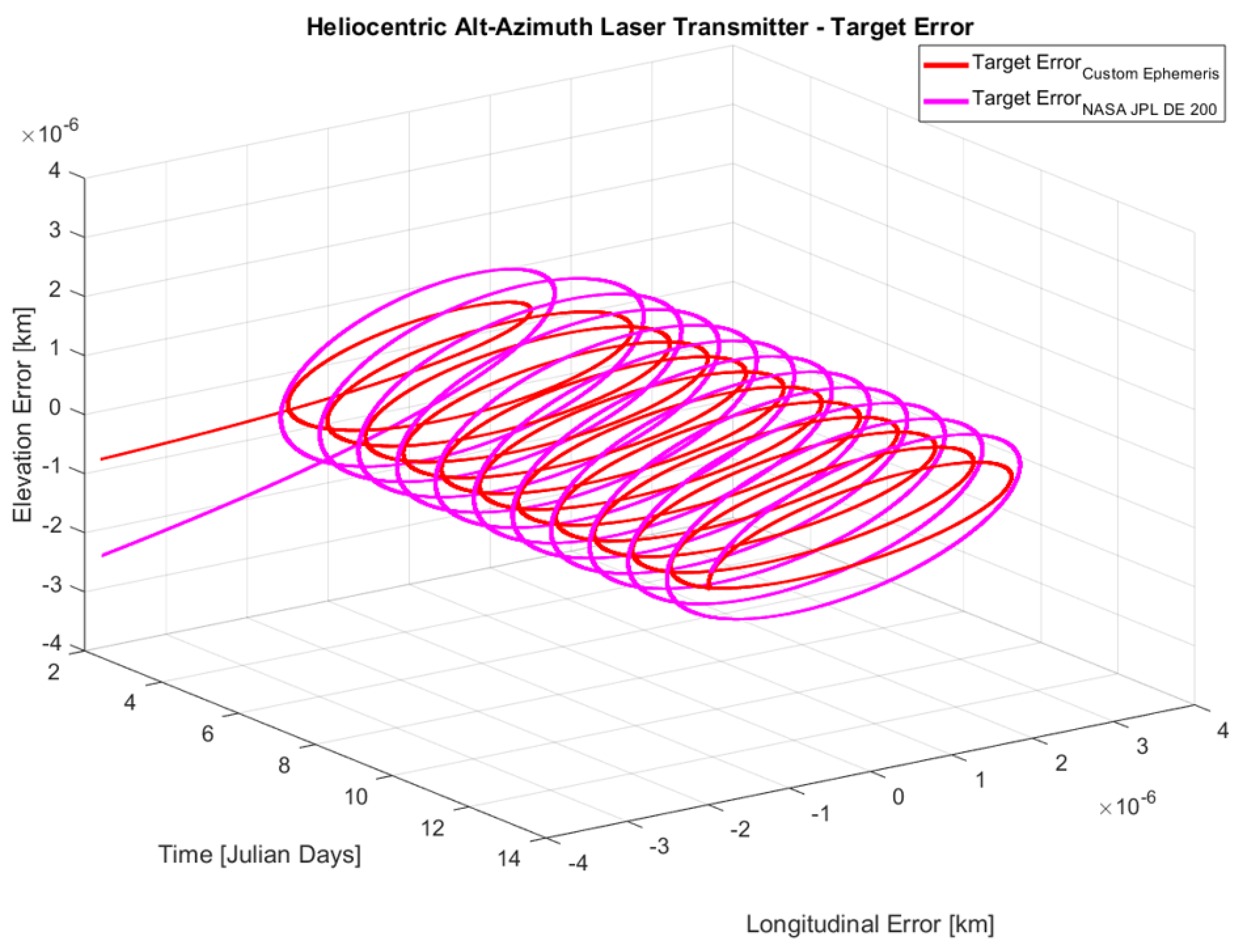
The comparison between the RIS and CIS orbital characteristics for target error is illustrated in
Figure 18 below.
The figure above shows a greater target error when using a high-accuracy planetary dataset. However, both characteristics show close results.
The target error comparison shown in the previous figure is associated with the torque control characteristics presented in
Figure 19 below.
This result shows a mean error close to zero for the RIS planetary ephemeris, while for the CIS dataset, the mean error presents an offset due to the increased complexity. This leads to difficult regulator compensation due to the required sum of exponential equations, as well as other complex operations, to represent the orbital trajectory. Primarily, both results indicate a predominantly regulated torque in the range of 10 micronewton-meters, as the space vacuum does not interact with the satellite’s angular accelerations.
The following section presents the simulation results for the second location.
3.2.2. Case Study: Charging Station at Union Glacier Camp, Antarctica
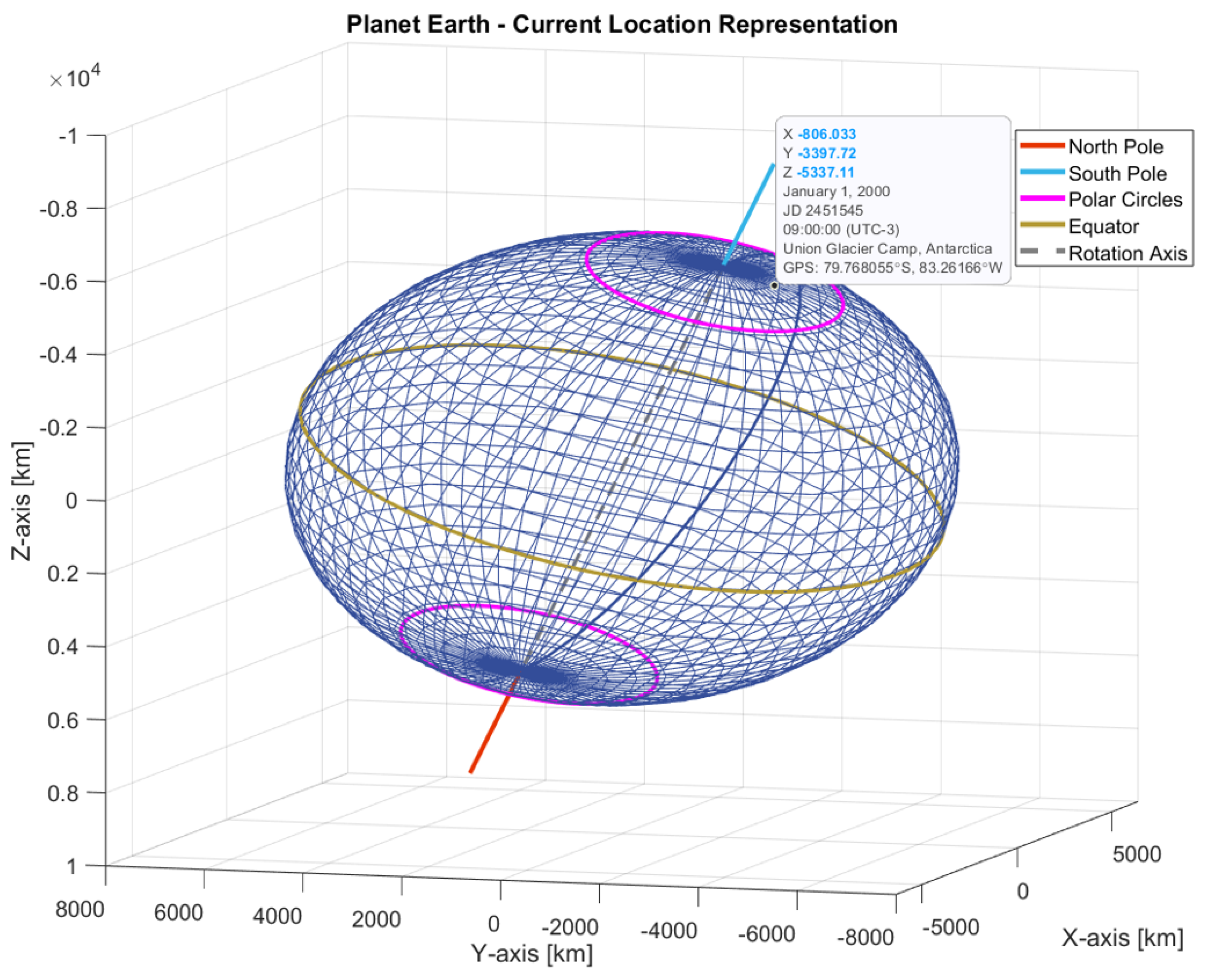
The charging station location or observer position in the simulation was adjusted to encompass additional scenarios, such as the position in the southern hemisphere near the geographic South Pole, as illustrated in
Figure 20. Similarly, the time displayed for this position corresponds approximately to the J2000 epoch time.
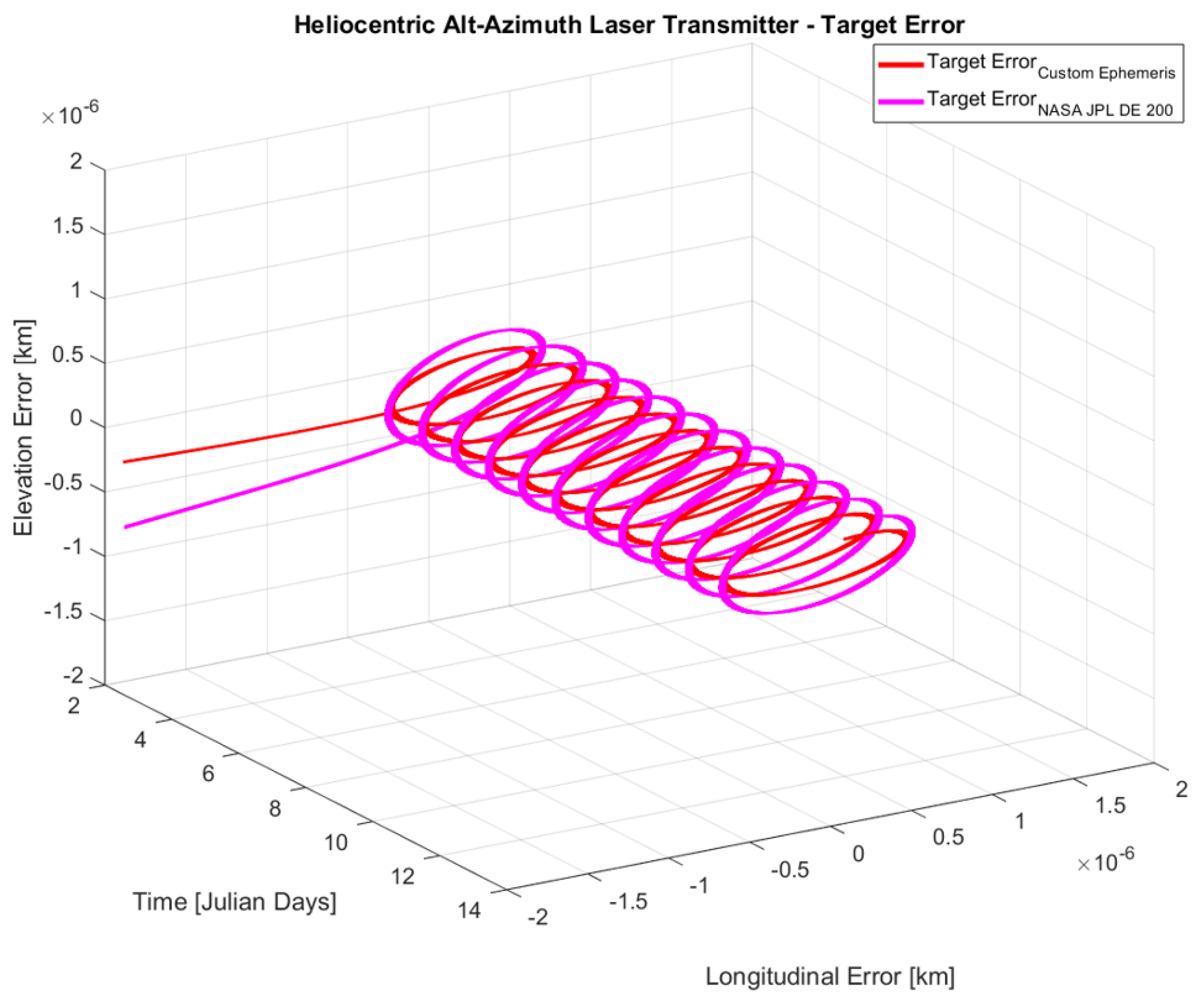
The RIS (Custom Ephemerides) and CIS (NASA JPL DE 200) planetary ephemerides were used to compare alt-azimuth regulation target errors, having the transient regime characteristics illustrated in
Figure 21.
Both cases below demonstrate a targeting mistake of less than 1 mm once the steady state has been reached. When replacing the RIS dataset with CIS orbital trajectories, like the location setting of Cluj-Napoca, the error increases by a small fraction, with both characteristics approaching a mean error of zero.
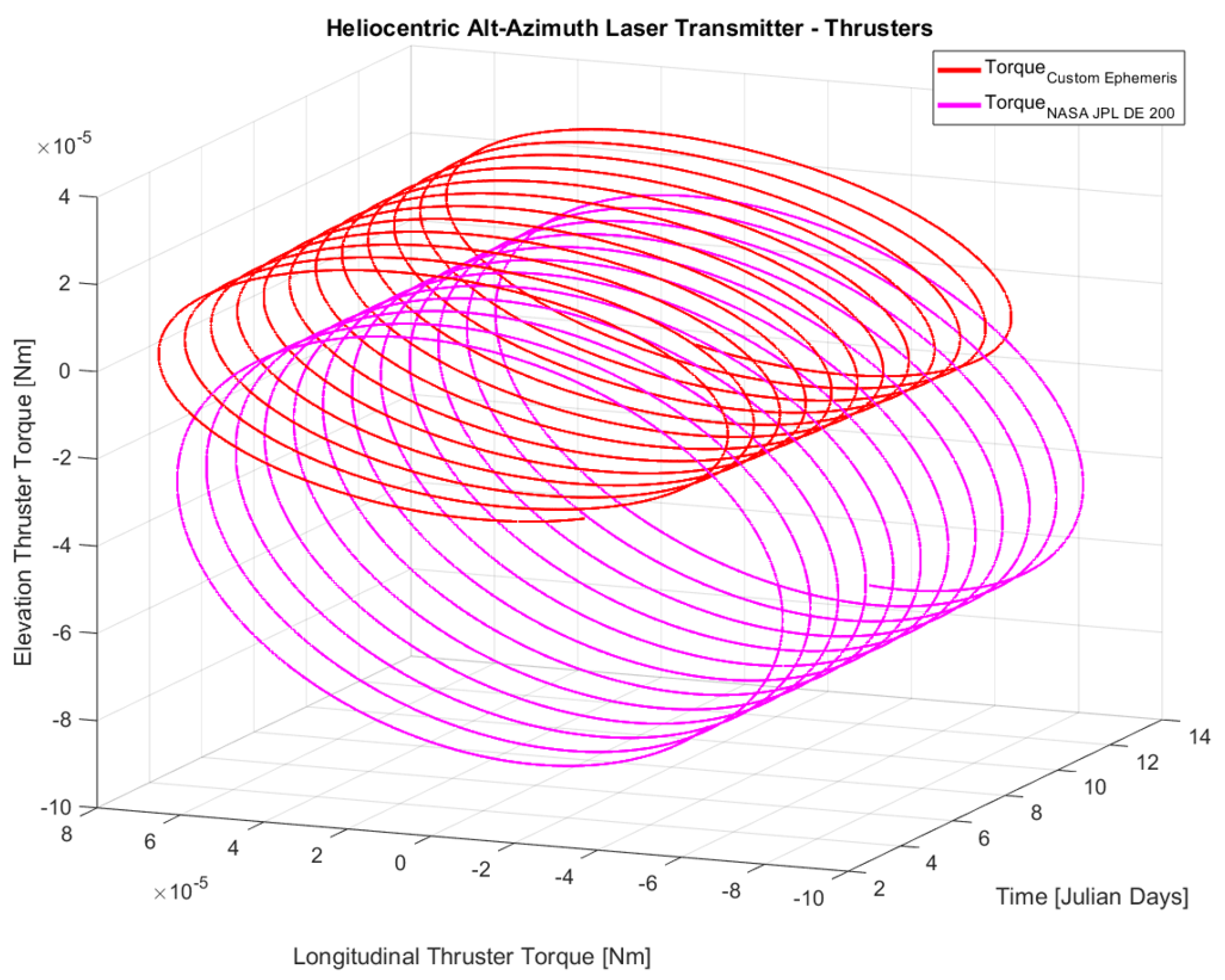
The thruster control characteristics illustrated below in
Figure 22 are associated with the previously presented figure for targeting error.
For RIS orbital trajectories, the mean thruster torque continuously maintains a value close to zero, corresponding to motion in a vacuum environment. However, a steady state offset is present for CIS planetary ephemerides due to the remaining gap in curvature compensation; this error could be mitigated by further iterating the mathematical power of the regulator. Similar to the first location, the torque output is maintained at a level of tens of micronewton-meters.
Based on the previously described orbital curvature compensation, the RIS orbital trajectories show consistency when compared to the results for CIS data, both of which are provided as inputs in the simulations. Based on these inputs, the output characteristics of the Simulink model were compared.
Due to the reduced complexity of RIS ephemerides, an improved preliminary optimization stage could be implemented to calibrate domains of variation for all alt-azimuth regulator parameters. The evaluation of GPU resources is covered in the next section.
3.3. Optimization of GPU Resources
The preliminary optimization improvement occurs due to the reduced data size for RIS characteristics compared to CIS, allowing for a greater number of parallel workers to be present in the optimization space. This, in turn, increases the probability of finding more suitable solutions for heuristic optimization algorithms.
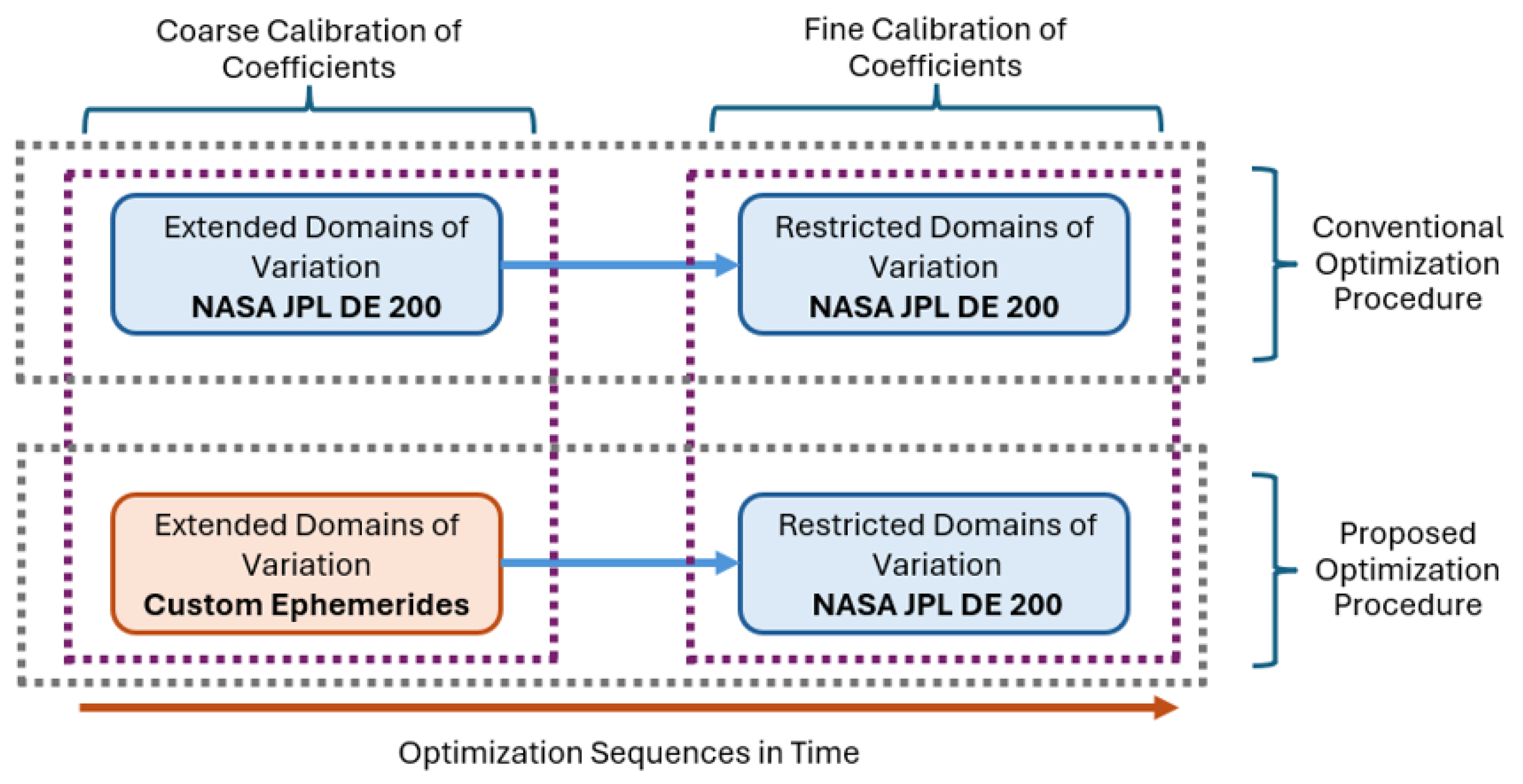
For defining the optimization procedure, the block diagram shown in
Figure 23 would typically be applied to achieve the hypothetical reduction in hardware memory usage.
From a mathematical point of view, by following the proposed optimization sequence, fewer hardware resources would be used due to the reduced complexity of RIS orbital characteristics. By using more than one stage for coarse calibration, further reduction in hardware resources can be achieved, optimizing the heuristic algorithm results by increasing the optimization agent density. The latter term refers to the distribution density of heuristic optimization agents in the search space, being applied for the same N-dimensional searching space when compared side-by-side to conventional optimization practices.
As a reference GPU, one of the latest devices was considered in evaluation, namely the NVIDIA RTX 5090 graphics card, which has a significant performance increase over its predecessors [
33]. All estimations are presented from a mathematical point of view, meaning that non-linear behaviors, such as the influence of AI (Artificial Intelligence) on performance or memory interpretation in embedded controllers, were neglected.
The resulting analysis of memory use for parallel optimization is presented in
Table 2.
Each parallel worker was tasked with storing the required data for simulating the heliocentric laser transmitter targeting system for the previously specified scenarios, which involved 14 Julian days. Additionally, the storage of simulation values was considered negligible due to the availability of rate transition blocks, which are typically used to change the sampling time of measurements, thereby minimizing the output data size from this model despite the complexity associated with reduced time constants, which require a smaller time step.
Overall, an increase of approximately 279.82% of parallel workers was possible in a hypothetical preliminary optimization stage. This stage, performed at one or more coarse levels, would result in providing the next optimization stage with a gradual reduction in the domains of variation for regulator coefficients. This, in turn, increases the optimization agent density, possibly improving the probability of reaching global optimum points during the calibration of the alt-azimuth regulator based on a predefined error characteristic for each direction of motion.
4. Discussion
To apply the study results to the main concept, further studies analyzed constraints in the development of this prototype. For complementing the optical SBSP energetic infrastructure, based on the state-of-the-art concepts for rocket thrusting technologies applied for the vacuum of space [
34], several rocket thruster classes can be identified. Considering the propulsion mechanism, the main rocket engine categories are represented by chemical thrusters and electric propulsion systems. For deep space missions, electric thruster technologies were previously used over rocket engines using chemical thrust [
35], the former class having the advantage of extended service life as well as increased specific impulse. The Hall thruster was previously evaluated for use in space missions, having this design in the experimental stage to provide an output force between 40 to 80 mN/kW [
36]. For ion thrusters, the output propulsion force reaches approximately 30 mN/kW. Furthermore, electric thrusting technology was studied for further improvements in contrast to the previously mentioned designs [
37], providing output forces in the range of 0.3 to 1 Newton at approximately 50,000 m/s specific impulse. State-of-the-art studies also include propulsion for satellites with reduced size [
38].
Based on the available rocket engine technologies, considering the resulting radius of the laser transmitter hypothetical satellite being equal to 100 m, the required engine force for achieving the simulation torque results by dividing this torque with thruster placement radius. Considering 50 m for this factor, the approximated output peak force for a hypothetical plasma engine results as described below, excluding steady state offsets:
The results from above highlight the need for increased accuracy in torque regulation. In addition to the closed-loop targeting, an additional feedback loop would be required at the laser transmitter side to accurately adjust the plasma engine output force. For the second location, being near the South Pole, the output force reaches values below 0.3 µN using the RIS dataset. Additional requirements for physical implementation would include calibrating force regulation to achieve fast responses without oscillations and ensuring the absence of dead zone characteristics in engine output regulation. The expected service life of such engines would be increased above the manufacturing specification due to applied force being significantly smaller than the peak output force.
For the in-discussion resource optimization, the percentage increase in parallel worker count was specified as a rough estimation, being approximately 279.82% from a mathematical point of view. Based on the increased optimization agent density, the resulting storage capacity of the RIS dataset for a single parallel worker is approximately 20.56 megabytes, which is 79.14% lower than the 98.57 megabytes of the CIS dataset. In practical experiments, the results may vary depending on the GPU used. Embedded controllers for memory allocation may behave differently depending on the device or producer, leading to a more or less pronounced variation in agent density with respect to the previously specified reference values, resulting in an increase or decrease in the optimization entity count.
5. Conclusions
In this research study, we aimed to develop a methodology concept for optimizing the coefficients from a hypothetical laser targeting regulator based on complex curvature characteristics in orbital dynamics. This study demonstrates that, unlike existing mathematical models of complex orbits, simplified instruction sets for orbital trajectories exhibit similar behavior when evaluated for simulation output, specifically in terms of error and rocket thruster output torque. The purpose was to optimize the use of GPU resources in the hypothetical heuristic calibration of alt-azimuthal controllers, resulting in a significant increase in optimization agents over high-accuracy datasets. This percentage decreased exponentially when analyzed from a dimensional perspective.
The present study involved multiple steps, starting with the development of RIS orbital characteristics, in improving the typical two-body problem dynamics. This simplified instruction set replicates the complexity of a perturbed barycentric motion for the orbital position of the terrestrial geocenter while maintaining mathematical complexity and minimizing data storage requirements. Having the geocentric position, further translations were applied to place the topographic target at a point defined by geographic coordinates, latitude, and longitude.
Further steps involved studying the dynamics of a satellite operating in the vacuum of space, hypothetically providing laser energy to the previously mentioned target. This approach considered a direct transfer from a heliocentric satellite to a ground charging station. However, future improvements can be implemented by restructuring the currently studied optical energy infrastructure. This would involve developing a different model and calibrating the controllers for multiple perturbed orbits typically encountered in transmitter, receiver, and intermediary satellites.
Having defined the hypothetical infrastructure based on RIS/CIS orbital dynamics, followed by targeting regulator implementation and vectorial translation definitions, the study continued by confirming the consistency of results for the developed reduced-complexity ephemerides. Targeting error and rocket output torque were maintained close to the case where the NASA JPL DE 200 dataset was used as input. Additionally, two locations defined by GPS coordinates were used as case studies for further validation of the RIS dataset to conclude the validity of using this set in one of the hypothetical optimization stages for targeting regulator calibration.
For future improvements, structural changes could include placing the satellite on a rotating orbit around the Sun and using intermediary transmitters. Various configurations can be applied in this topology, such as matching the satellite’s revolution period to that of the Earth and then using additional receiver–transmitter points to minimize relativistic effects. This, in turn, would minimize the risk of undesired consequences during operation. Furthermore, as previously studied, the applicability of this main concept involves analyzing and solving unexpected situations and possible consequences, overcoming territorial limitations, and examining and addressing legal implications.

