Article

Mechanical Design, Analysis, and Dynamics Simulation of a Cable-Driven Wearable Flexible Exoskeleton System

1
Department of Mechanical and Automation Engineering, The Chinese University of Hong Kong, Hong Kong 999077, China
2
Faculty of Dentistry, University of Malaya, Kuala Lumpur 50603, Malaysia
3
School of Electrical and Mechanical Engineering, The University of Adelaide, Adelaide 5006, Australia
4
College of Engineering Machinery, The Chang’an University, Xi’an 710061, China
*
Author to whom correspondence should be addressed.
Technologies 2024, 12(12), 238; https://doi.org/10.3390/technologies12120238
Submission received: 11 October 2024 / Revised: 12 November 2024 / Accepted: 16 November 2024 / Published: 21 November 2024
(This article belongs to the Section Assistive Technologies)

Abstract

:
As a new development direction in exoskeleton research, wearable flexible exoskeleton systems are highly favored for their freedom of movement, flexibility, lightweight design, and comfortable wearability. These systems are gradually becoming the preferred choice for rehabilitation therapy, and enhancing physical performance. In this thesis, based on existing research in wearable flexible exoskeletons, we aim to design a lightweight wearable upper limb rehabilitation exoskeleton that meets the needs of stroke patients with a high likelihood of upper limb impairment. The system should provide sufficient flexibility for comfortable and convenient use while minimizing the weight to reduce the user’s burden during wear. Our proposed lightweight wearable flexible exoskeleton assists users in achieving rehabilitation exercises for both the shoulder (external/internal rotation) and forearm (flexion/extension) movements. The system consists of a flexible fabric section connecting the torso–shoulder–upper arm, a flexible fabric section for the forearm, and a back-mounted actuation device. The fabric sections primarily consist of elastic textile materials with a few rigid components. Emphasizing lightweight design, we strive to minimize the exoskeleton’s weight, ensuring optimal user comfort. The actuation device connects to the fabric sections via tensioned wires, driven by a motor to induce arm movement during rehabilitation exercises. To enhance safety and prevent secondary upper limb injuries due to exoskeleton malfunction, we incorporate a physical limiter retricting the exoskeleton’s range of motion. Additionally, we include tension-adjustment mechanisms and cushioning springs to improve the feasibility of this wearable flexible exoskeleton. After completing the structural design, this paper conducted a basic static and kinematic analysis of the exoskeleton system to provide theoretical support. Additionally, the feasibility and effectiveness of the exoskeleton system design were verified through dynamic simulations.

1. Introduction

Upper limb disability by stroke is a severe central nervous system motor disorder where patients experience partial loss of limb function, resulting in hemiparesis [1]. For individuals with upper limb disability, rehabilitation therapy is crucial. It aims to re-establish connections between the limbs and the brain’s damaged central nervous system, gradually stimulating recovery in the affected brain regions to achieve effective control over limb behavior [2,3]. With advancements in modern medical technology, research on rehabilitation robotic arm systems has opened up new effective avenues for upper limb hemiparetic patients and garnered widespread attention [4,5]. Compared to traditional manual and physical therapies, rehabilitation robotic arm systems offer advantages in precision, personalization, and systematic training tailored to patients’ varying motor abilities and rehabilitation needs [6,7]. These systems can be classified into two main types: end-effector-based and exoskeleton-based robotic arms. Yekaterina Ponomarenko developed an electromagnetically powered end-effector-based robotic manipulator with seven degrees of freedom for post-stroke physical therapy. The system provides three degrees of freedom in the shoulder joint and two degrees of freedom in the elbow joint [8]. Researchers at Kagawa University in Japan developed an innovative rehabilitation robot for the elbow. This robot is designed to enhance the user’s natural joint range of motion and adapt to intrabody variability. It achieves this through five passive degrees of freedom. Additionally, the robot features an integrated variable stiffness actuator (VSA) that independently adjusts joint stiffness by altering the pivot position. The goal is to optimize rehabilitation outcomes while ensuring user comfort and safety [9]. Furthermore, Manuel Andrés Vélez-Guerrero also invented a single-degree-of-freedom rigid wearable exoskeleton. The system mainly comprises four semi-rigid support paddles that provide lateral support to the arm and forearm segments, attached at each end to a lightweight articulated structure that allows their movement [10]. From the examples above, it can be observed that research on rehabilitation robotic arms has transitioned from end-effector-based systems to wearable exoskeletons. However, existing studies on wearable rehabilitation exoskeletons still reveal the following challenges:
  • Existing wearable robotic arms are often rigid, excessively heavy, and lack the necessary flexibility for effective rehabilitation. Ideally, a robotic arm should be lightweight, agile, smooth, and closely conform to the patient’s arm.
  • The robotic arm should have appropriate degrees of freedom and a simple structural design. This ensures effective rehabilitation while minimizing the burden on patients during use.
  • The robotic arm should exhibit extremely high stability and safety.
To address these challenges, this paper proposes a wearable exoskeleton system that meets the rehabilitation needs of stroke patients while providing flexibility, comfort, and minimal weight for ease of use. The lightweight flexible exoskeleton system designed here has three DOFs, assisting users in performing rehabilitation exercises for both shoulder (external/internal rotation) and forearm (flexion/extension) movements. Its mechanical structure consists of a flexible fabric section connecting the torso–shoulder–upper arm, a flexible fabric section for the forearm, and a back-mounted actuation device. The fabric sections primarily comprise flexible textiles with a few rigid components. The system is driven by a motor, with tensioned wires connecting the actuation device to the fabric sections. The motor rotation induces wire contraction, resulting in arm movement during rehabilitation exercises. Additionally, a physical limiter restricts the exoskeleton’s motion to enhance user safety, effectively preventing risks from improper use or equipment malfunction. This design incorporates tension-adjustment mechanisms and cushioning springs that mimic human muscle stretch, enhancing the feasibility of this wearable flexible exoskeleton. Calculations and analyses were performed for the limiter and cushioning springs. Additionally, this paper conducts a basic kinematic analysis, static analysis, and dynamic simulation of the designed exoskeleton system, thereby providing more comprehensive theoretical support for the exoskeleton design.

2. Mechanical Design

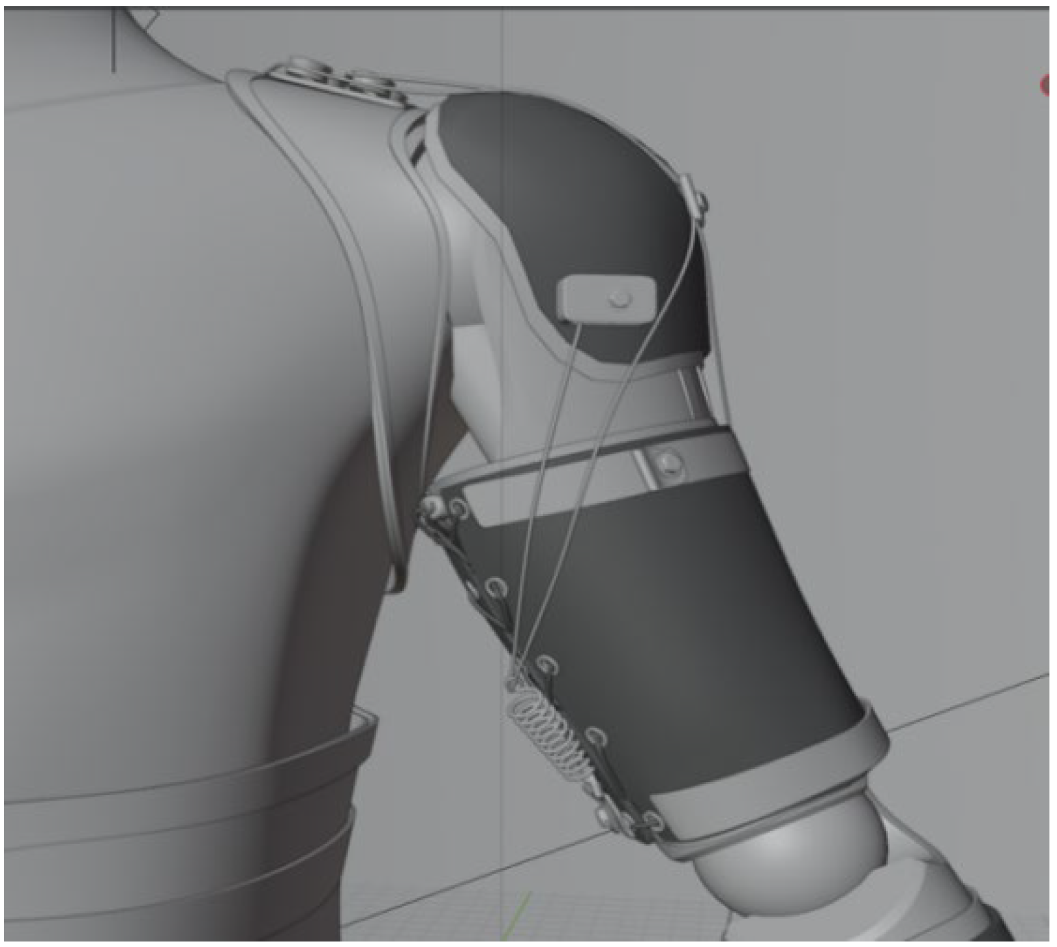
2.1. Structural Design

The lightweight wearable soft exoskeleton described in this article mainly consists of the following components: a flexible fabric section integrating the torso, shoulders, and upper arms; a flexible fabric section at the forearm; steel wires for transmitting driving force; a drive unit for providing force; U-shaped bearings on the inner side of the shoulder fabric to alter the direction of wire tension; rigid materials sewn onto the fabric at the upper arm and forearm to provide necessary mounting positions for the transmitting wires; springs connecting the wires to the fabric; and limiters sewn into the shoulder fabric to prevent joint reversal. The overall conceptual design diagram of the wearable robotic arm is shown in Figure 1.
The flexible robotic arm consists of the torso–shoulder–upper arm main fabric and the separately worn lower arm fabric section. On the inner side of the shoulder portion of the flexible fabric, two rows of rigid pads are sewn in place. U-shaped bearings are installed on these pads to alter the direction of tension in the steel wires. The U-shaped bearings have a center diameter smaller than the edge diameter, which prevents the steel wires from sliding up and down during the actuation process, thus avoiding detachment from the bearings. Refer to Figure 2 for illustration.
The upper arm fabric section has an alloy ring labeled as ‘Ring 2’ at the lower edge. Two anchor points, designated as ‘Anchor 1’ and ‘Anchor 2’, are installed on this alloy ring. Similarly, at the upper edge, there is another alloy ring labeled as ‘Ring 3’, with two anchor points, ‘Anchor 3’ and ‘Anchor 4’, attached.
Anchors 1 and 2 consist of bolts, perforated washers, and nuts. Anchors 3 and 4 are simple perforated structures. Four steel wires emerge from the rear-mounted drive system: wire 1, wire 2, wire 3, and wire 4. At Anchors 1 and 2, the washers connect one end of a spring, while the other end of the spring is attached to wires 1 and 2 responsible for actuating the upper arm. The spring stretches as the wires are tensioned, driving the upper arm’s movement. Adding a spring mechanism between the anchors and the wires buffers the direct driving force, enhancing flexibility. For the lower arm movement, wires 3 and 4 pass through Anchors 3 and 4 and connect to the forearm. Anchors 3 and 4 restrict the motion trajectory of wires 3 and 4, simulating real muscle contraction. The wires and springs analogize human muscle contraction and extension, with the anchors representing tendons, thereby reducing the angle between the wires and the forearm.
In the forearm fabric section, an alloy ring labeled as ‘Ring 1’ positioned at the middle of the forearm. Two anchor points, designated as ‘Anchor 5’ and ‘Anchor 6’, are installed on this alloy ring, distributed on the upper and lower sides of the forearm.
Anchors 5 and 6 consist of bolts, perforated washers, and nuts. The washer at Anchor 5 connects one end of a spring, while the other end of the spring is attached to wire 3, passing through Anchor 3. Similarly, the washer at Anchor 6 connects one end of another spring, with the opposite end of the spring connected to wire 4, passing through Anchor 4.
The upper arm and forearm fabric sections have a series of holes arranged vertically at both ends. Each end has five holes. Ropes are threaded through these holes and elastic adjustment buckles are placed at the top. Users can adjust the tightness of the upper arm fabric by pulling on the hanging ropes. The specific mechanical structure design is as shown in Figure 3 and the cable tensioning mechanism is as shown in Figure 1.
The upper arm and forearm fabric sections have two layers of different flexible materials stitched together. The inner layer material is silicone. Using silicone as the inner-layer structure increases the friction between the exoskeleton device and the user’s arm, effectively preventing the fabric from sliding up and down during the actuation process.
There is a limit device and ‘Anchor 7’ at the shoulder portion of the fabric. After passing through the spring, wires 1 and 2 are connected to the limiters. Further upward extension is prevented when the spring is stretched to the limiter position, thus avoiding joint reversal.
As shown in Table 1, the maximum range of motion for internal and external rotation of the upper arm is only 90 degrees, while the flexion–extension motion of the forearm has a maximum range of 150 degrees. Therefore, it is necessary to set a motion limiter for the upper arm but not for the forearm. The structure of the limiter is illustrated in Figure 4.

2.2. Dimensional Determination

The lightweight upper limb wearable flexible exoskeleton system should closely match human body dimensions, providing users with better comfort and improved assistive effects. Therefore, in the design of this wearable flexible rehabilitation exoskeleton system, dimension design is a crucial aspect. From [11], it can be observed that the most widely distributed height range among males is 173 cm to 177.9 cm, while, among females, it is 160.7 cm to 166.7 cm. This significant difference in height between genders makes it impossible to design a universally applicable lightweight upper limb wearable rehabilitation robotic arm system that meets everyone’s needs. Therefore, in the initial design phase, this study selects an optimal value from these ranges. Subsequently, as the design is refined, the robotic arm will be further sized according to clothing size standards (S, M, L, XL, and XXL). In this study, a height of 175 cm and a weight of 70 kg are chosen as the standard design dimensions. Referring to [12] for estimating arm weight, Table 2 can be derived.
Table 2 shows that the estimated parameters still exhibit some deviation from the baseline parameters. However, the impact of estimated parameter errors can be mitigated due to the inherent variability in human body parameters and the structural design and materials of the wearable rehabilitation exoskeleton proposed in this study. Therefore, this paper will use the estimated parameters as reference data for designing a lightweight upper limb wearable rehabilitation exoskeleton.
According to the standard arm dimensions for adult males and considering that stroke patients often have relatively slender arms due to prolonged lack of exercise, this study selects the unfolded length (L1) of the upper arm fabric as 28 cm, with a height (h1) of 20 cm and a thickness (d1) of 1 cm. There are alloy rings with identical parameters at both the upper arm fabric’s lower and upper edges. The circumference (L2) of these rings is 26 cm, their width (h2) is 2 cm, and their thickness (d2) is 0.5 cm. The alloy ring at the upper edge is positioned at a distance (b) of 20 cm from the elbow joint. To connect the wires, springs with a length (L3) of 10 cm and a stiffness coefficient (k1) of 0.59 (simulating the extensibility of the biceps brachii muscle) are used. The holes in the upper arm fabric have a radius (R1) of 0.25 cm, and the distance between the centers of the two holes (x1) is 4.75 cm. The hole centers at the upper and lower edges of the fabric are separated by a distance (x2) of 0.5 cm.
The unfolded length (L4) of the forearm fabric is 18 cm, with a height (h3) of 20 cm and a thickness (d3) of 1 cm. In the middle portion of the forearm fabric, there is also an opening with an alloy ring. The circumference (L5) of this ring is 16 cm, its width (h4) is 2 cm, and its thickness (d4) is 0.5 cm. The spring connecting the wires in the forearm section has a length (L6) of 3 cm and a stiffness coefficient (k2) of 2. The upper edge of the ring is positioned at a distance (a) of 12 cm from the edge of the forearm fabric near the elbow joint. The holes in the forearm fabric have a radius (R2) of 0.25 cm, and the distance between the centers of the two holes (x3) is 4.75 cm. The hole centers at the upper and lower edges of the fabric are separated by a distance (x4) of 0.5 cm.
In the fabric section connecting the torso to the shoulder, a limiter is placed at the lower edge of the fabric to prevent joint reversal and secondary injury to the user. The limiter has an end face length (L7) of 4 cm and a width (h5) of 3 cm. Internally, it utilizes an ultra-precision U-shaped bearing with a radius (R3) of 0.9 cm.
Here, this paper summarizes all the mentioned parameters in the following table, as shown in Table 3.

2.3. Driving System Design

The driving system of the wearable rehabilitation exoskeleton designed in this study is a multi-power-source device that utilizes four steel wires to control shoulder and elbow joint movements [13]. The internal structure includes four sets of nearly identical drive modules. Each module consists of a brushless motor, a synchronous belt (pulley), a lead screw nut, optical guides, and a nut guide frame. The basic working principle involves the motor rotating the lead screw via the synchronous belt (pulley), which, in turn, drives the nut guide frame (fixed to the nut) to move linearly (the optical guides restrict the rotation of the nut guide frame). Wire tension can be adjusted by securing one end of the steel wire to the nut guide frame, capable of linear reciprocating motion. A limit switch is installed internally to establish the initial position when the device is powered on. A limit switch is installed internally to establish the initial position when the device is powered on. This system drives shoulder and elbow joint movements. Considering the joint characteristics, the shoulder joint is approximated as a ball joint, allocated to two sets of drive modules for quarter-circle swinging in both directions. The elbow joint is approximated as a rotational joint, allowing half-circle swinging in the vertical plane. Two sets of drive modules are assigned to the elbow joint. During normal operation, the system performs self-check upon power-up, rotating the motor until the limit switch is triggered and establishing the 0 position. When the system detects motion intent through various sensors, it calculates and controls wire tension to execute the corresponding movement. At the same time, to address the issue of the wire-driven system with a timing belt potentially becoming loose over time, this study selected an elastic automatic tensioner (spring-loaded mechanical tensioner) to help maintain constant tension in the timing belt. As for the power supply part, this paper adopts a cable-powered approach based on the lightweight design concept. The schematic diagram of the mechanism is shown in Figure 5.

2.4. Weight Estimation

The most notable feature of the rehabilitation exoskeleton designed in this paper is its lightweight design. However, since the physical model has not yet been completed, this section primarily estimates the weight range of the rehabilitation exoskeleton designed in this paper and compares it with the weight of existing lightweight upper limb rehabilitation exoskeletons on the market.
Estimating the weight of the rehabilitation exoskeleton system designed in this paper can be divided into four parts: the drive box, the steel wires, the flexible fabric, and other components. The other components include springs, nuts, washers, and alloy rings.
The weight of the drive box mainly comes from the internal motors and synchronous pulleys. The exoskeleton system designed in this paper requires eight small brushless motors to drive the exoskeleton, with each small brushless motor weighing approximately 50 g. Therefore, the weight of the entire drive box is estimated to be around 700 g to 1 kg.
The weight of the steel wires can be calculated using the following formula:
W = ρ × π × D 2 2 × L
where W is the weight of the steel wire; ρ is the density of the steel; D is the diameter of the steel wire; and L is the length of the steel wire. Here, D is 3 mm and L is 8 m, so the weight of the wire can be calculated to be approximately 444 g.
The weight of the flexible fabric is approximately 400 g and the weight of the other components is about 600 g. Therefore, in summary, the estimated total weight of the rehabilitation exoskeleton system designed in this paper is between 2.5 kg and 3 kg.
Some upper limb rehabilitation exoskeletons on the market aim to reduce weight while providing sufficient support and flexibility. Examples include ARMin IV, RUPERT, and UL-EXO7 [14,15,16]. These upper limb rehabilitation exoskeletons each weigh around 10 kg. Therefore, it is evident that the upper limb rehabilitation exoskeleton system designed in this paper is significantly superior to other upper limb rehabilitation exoskeleton products on the market in terms of lightweight design. The specific weight comparison table is shown below in Table 4.

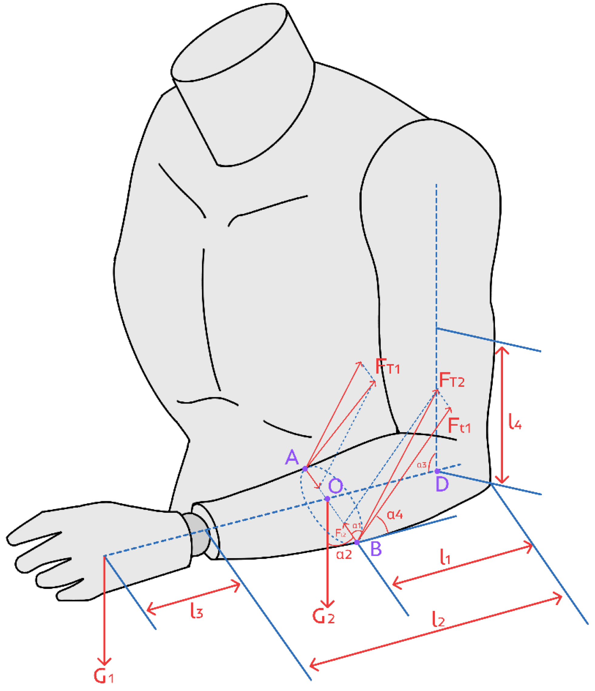
3. Kinematic and Static Analysis

3.1. Kinematic Analysis

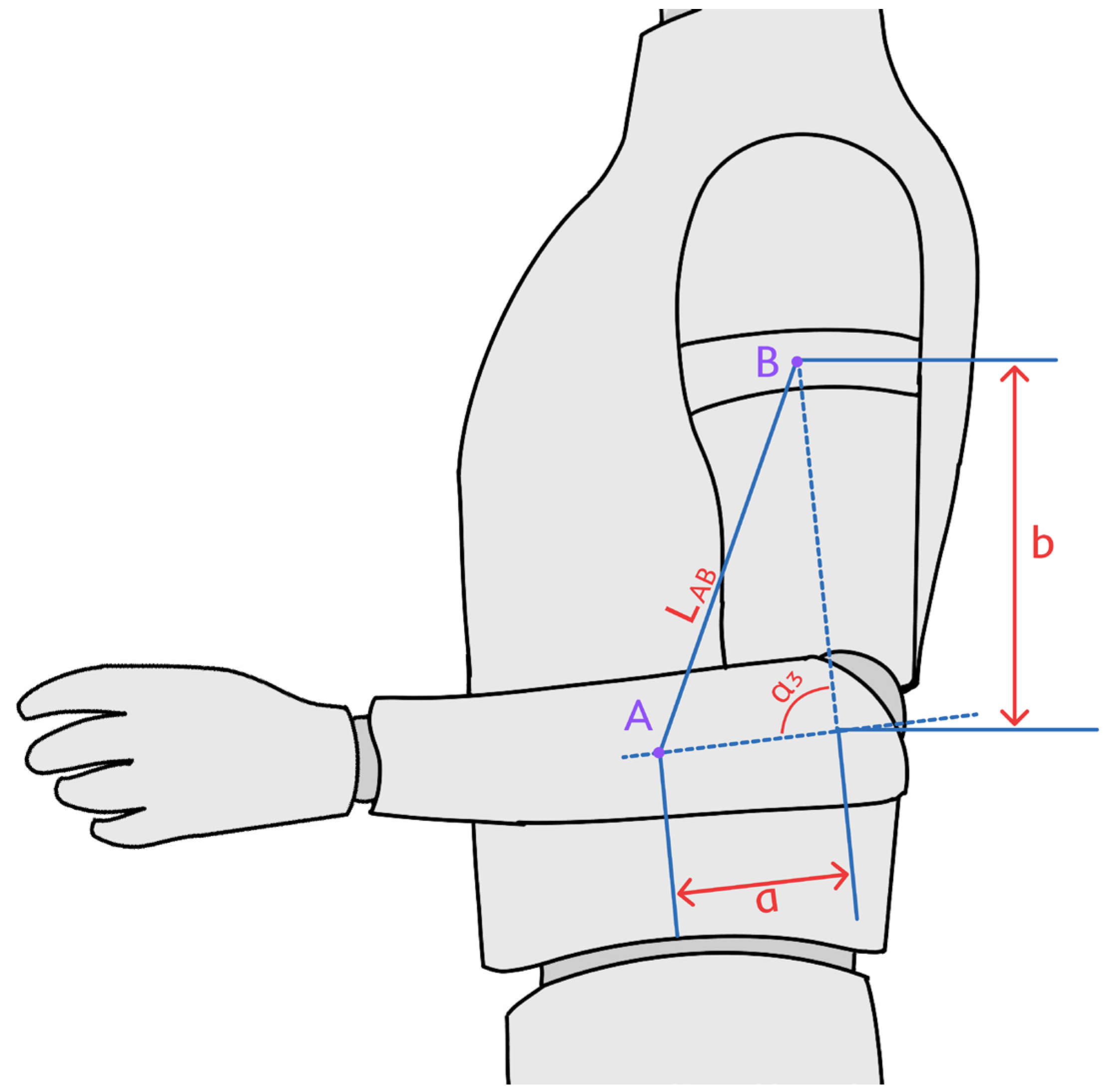
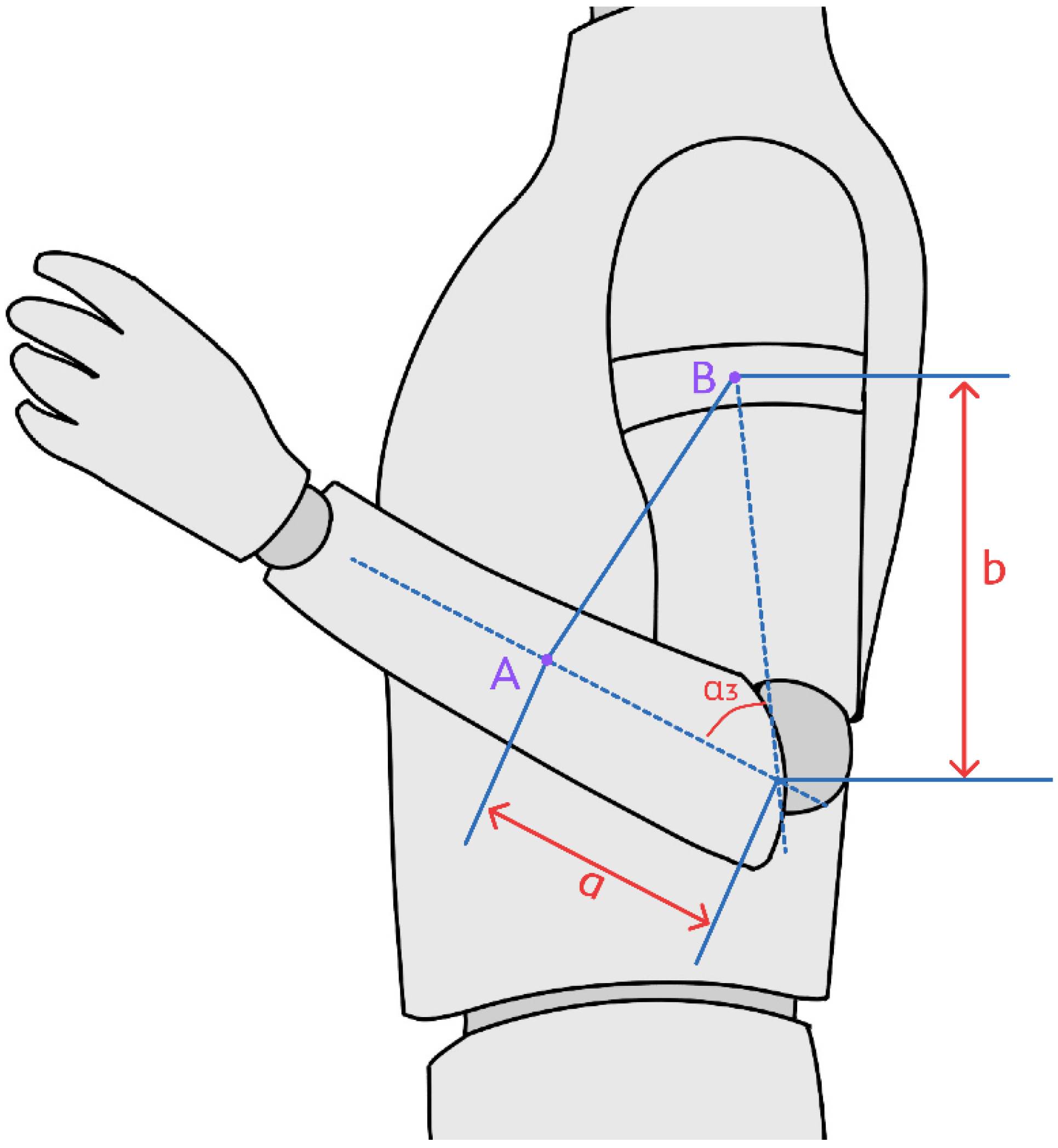
3.1.1. Kinematic Analysis of the Upper Arm

The process of the exoskeleton driving the upper arm to perform external/internal rotation of the shoulder joint, it is achieved through the contraction/extension of the steel wire. Therefore, in the design process, it is necessary to analyze the relationship between the driving steel wire’s extension amount and the upper arm’s movement angle to achieve the desired design effect, as shown in Figure 6 and Figure 7.
The angle α 7 formed between the arm and the torso is the angle between the gravitational force and the arm axis in the static analysis. The initial length of the spring between the fixed point of the upper arm and the steel wire is l 0 . With the rotational movement of the upper arm, the final length of the spring is set to l 1 .
Then, we can obtain:
l = l 1 l 0
According to the spring constant formula, we can obtain:
F = l 1 l 0 × k = l × k
Furthermore, from the static analysis of the main arm, we can obtain:
F = 2 F t 3 = G T o t a l × sin α 7 cos α 5
In summary, we can obtain:
l × k = G T o t a l × sin α 7 cos α 5
By rearranging the equation, we obtain:
l = G T o t a l × sin α 7 k × cos α 5
According to the above text, the stiffness coefficient k, angle α 5 , and G T o t a l are known quantities. Therefore, this equation is a relationship between l and angle α 7 .

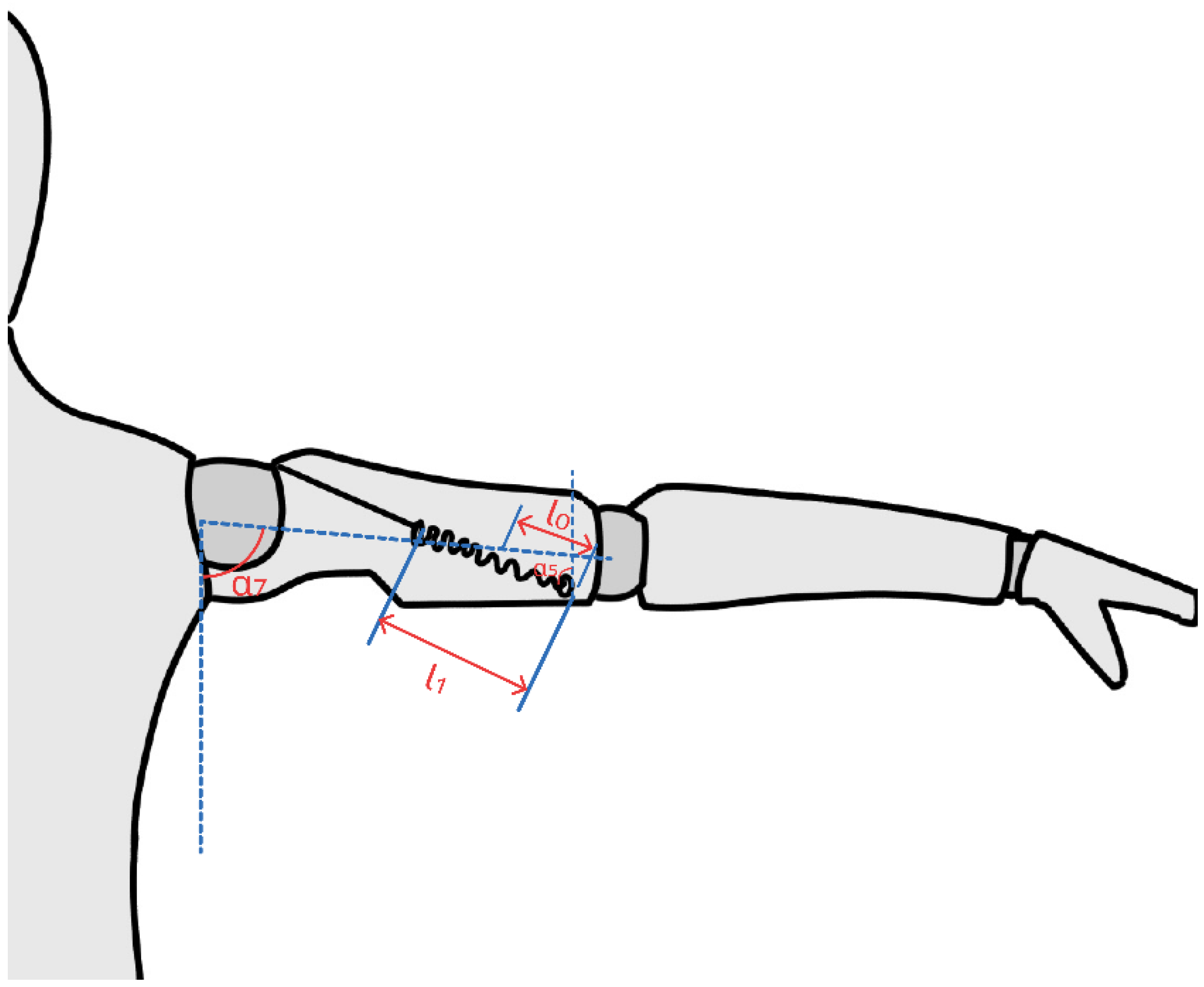
3.1.2. Kinematic Analysis of the Forearm

In the process of the exoskeleton driving the forearm to perform elbow flexion/extension rehabilitation exercises, it is achieved by contracting/extending the steel wire. Therefore, during the design process, it is necessary to analyze the relationship between the extension amount of the driving steel wire and the angle between the forearm and the upper arm to achieve the desired design effect, as shown in Figure 8 and Figure 9.
The angle between the axis of the upper arm and the forearm is α 3 . According to Table 3 in Section 2.2, the distance a from the driving fixed point on the alloy ring of the forearm’s woven part to the elbow joint is:
a = 12 c m
The distance b from the driving fixed point on the alloy ring, which is responsible for securing the driving steel wire of the forearm in the woven part of the upper arm, to the elbow joint is:
b = 20 c m
Let the distance from the driving fixed point A on the alloy ring of the forearm to the driving fixed point B on the alloy ring responsible for securing the driving steel wire of the forearm in the upper arm be L A B . According to trigonometric functions, we obtain:
L A B 2 = a 2 + b 2 2 a b × cos α 3
Taking the square root of both sides of the equation, we obtain:
L A B = a 2 + b 2 2 a b × cos α 3
When the arm is naturally hanging down, α 3 = 180 ° and L A B is the distance between the driving fixed point on the alloy ring of the forearm’s woven part and the driving fixed point on the alloy ring responsible for securing the driving steel wire of the forearm in the upper arm, which is:
L A B I n i t i a l = a + b
Thus, during the elbow flexion/extension rehabilitation exercises of the forearm, the extension amount L of the driving steel wire is:
L = L A B L A B I n i t i a l
Therefore:
L = a 2 + b 2 2 a b × cos α 3 a + b
Since a and b are known quantities, this equation can reflect the relationship between the extension amount of the driving steel wire and the elbow joint rotation angle (the angle between the upper arm and the forearm) during the elbow flexion/extension rehabilitation exercises of the forearm.

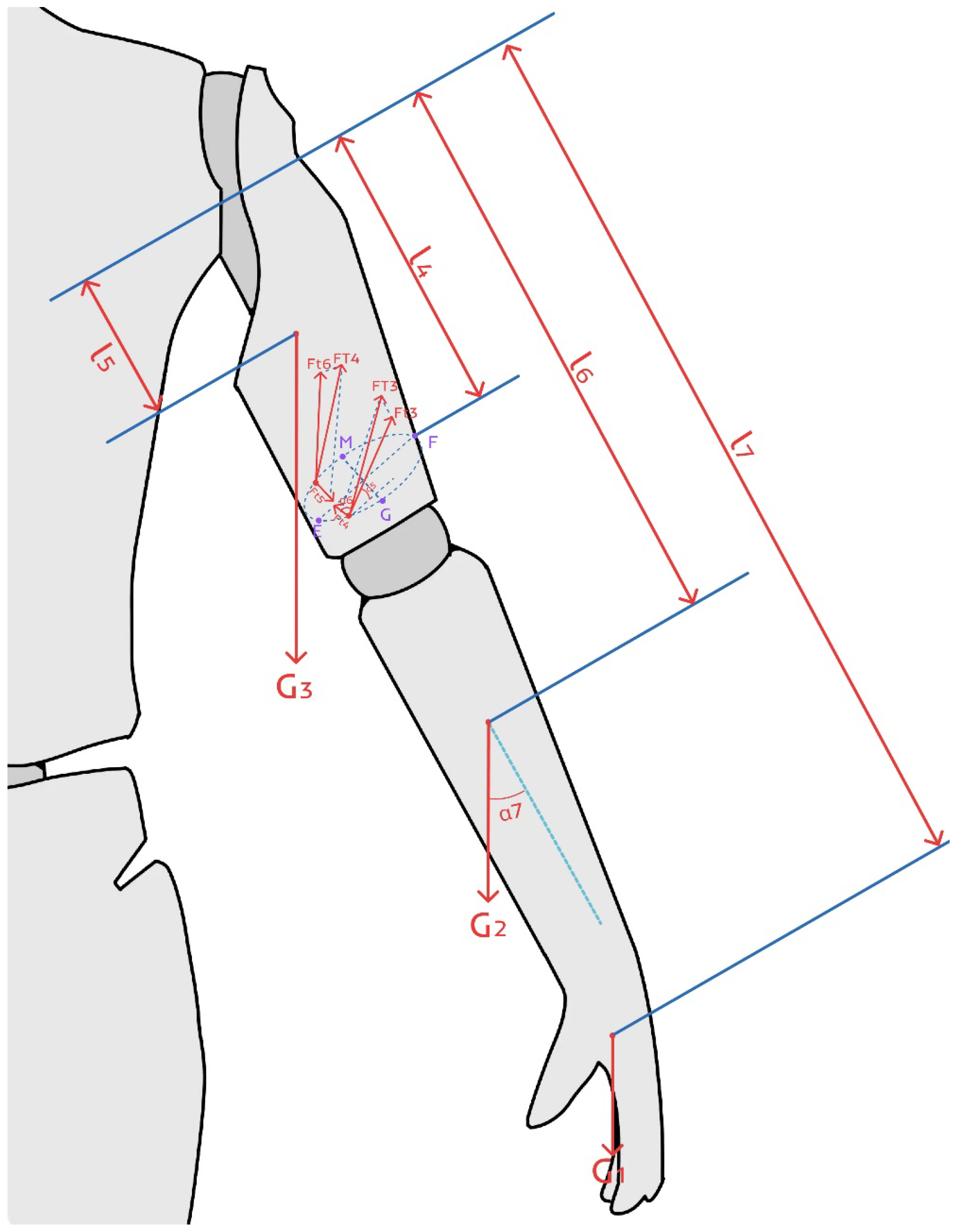
3.2. Static Analysis

3.2.1. Static Analysis of the Upper Arm

The primary rehabilitation exercise for the upper arm is achieved through the internal/external rotation of the shoulder joint. When the driving device controls the movement of the upper arm by stretching the wire that drives the upper arm to perform internal/external rotation of the shoulder joint, the tension in the wire needs to overcome the gravitational forces acting on the upper arm, forearm, and hand. Let the gravitational force on the hand be G 1 , on the forearm be G 2 , and on the upper arm be G 3 . Therefore, we have:
G 1 = m P a l m × g
G 2 = m F o r e a r m × g
G 3 = m U p p e r a r m × g
The theoretical force analysis of the shoulder joint’s external rotation is shown in Figure 10.
The tension in the driving wires acting on the upper arm is represented by F T 3 and F T 4 . The distance from the shoulder to the cross-section where the wire tension is applied is L 4 , the distance from the shoulder to the center of mass of the upper arm is L 5 , the distance from the shoulder to the center of mass of the forearm is L 6 , and the distance from the shoulder to the center of mass of the hand is L 7 . In practical use, the two tensions F T 3 and F T 4 are not perfectly parallel forces but forces with a certain angle between them in three-dimensional space. Since the angles between F T 3 and F T 4 and the cross-section of the upper arm is equal, let the angle be α 6 . By decomposing the forces, the tensions F T 3 and F T 4 can be resolved into two equal and opposite forces F t 4 and F t 5 along the GM direction. In the plane parallel to the axis (perpendicular to the cross-section of the arm), they can be decomposed into two equal and same-direction forces: F t 3 and F t 6 . Here, taking F T 3 as an example, it is decomposed as follows:
F t 3 = F T 3 × sin α 6
F t 4 = F T 3 × cos α 6
Similarly, F T 4 can be decomposed into a force F T 5 that is equal in magnitude and opposite in direction to F T 4 ; thus, the two forces can cancel each other out.
To achieve the desired rehabilitation effect of the robotic arm, the tension applied by the driving wires to the upper arm should balance the gravitational forces acting on the upper arm, forearm, and hand. The total tension applied by the driving wires to the upper arm is:
F 2 = F T 3 + F T 4
According to the formula:
F 2 = F T 3 + F T 4
F t 4 = F T 3 × cos α 6
Based on the above analysis, in the plane where the driving tension and gravitational forces are decomposed for equilibrium, F 2 can be simplified as:
F 2 = F t 3 + F t 6 = 2 F t 3
The total gravitational force acting on the upper arm during the external/internal rotation of the shoulder is:
G T o t a l = G 1 + G 2 + G 3
By decomposing G 1 , G 2 , G 3 , and F T 3 as shown in Figure 4 and Figure 5, where the angles between G 1 , G 2 , G 3 and the arm’s axis are α 7 and the angle between F T 3 and the EF axis is α 5 , we obtain:
G T o t a l × cos α 7 = F 2 × sin α 5 = 2 F t 3 × sin α 5
G T o t a l × sin α 7 = F 2 × cos α 5 = 2 F t 3 × cos α 5
Regarding the torque analysis of the shoulder on the entire arm, we obtain:
G r a v i t a t i o n a l t o r q u e = G 1 × L 7 + G 2 × L 6 + G 3 × L 5 × sin α 7
T e n s i o n t o r q u e = 2 F t 3 × cos α 5 × L 4
During the process of the driving wires moving the upper arm, it is also necessary to ensure torque balance. Therefore, we obtain:
G 1 × L 7 + G 2 × L 6 + G 3 × L 5 × sin α 7 = 2 F t 3 × cos α 5 × L 4

3.2.2. Static Analysis of the Forearm

The primary rehabilitation exercise for the forearm is achieved through the flexion/extension movement of the elbow joint. The theoretical force analysis of the elbow joint’s flexion movement is shown in Figure 11.
When the driving device moves the forearm through the flexion/extension movement of the elbow joint using wires fixed at both ends of the forearm, the tension in the wires needs to overcome the gravitational forces acting on the forearm and hand. Let the gravitational force on the hand be G 1 and on the forearm be G 2 . Therefore, we obtain:
G 1 = m P a l m × g
G 2 = m F o r e a r m × g
The tension in the driving wires acting on the forearm is represented by F T 1 and F T 2 . The distance from the center of mass of the hand to point C at the wrist is L 3 , the total length of the forearm is L 2 , the distance from the center of mass of the forearm to the elbow is L 1 , and the distance from the center of mass of the upper arm to the elbow is L 4 . In practical use, the two tensions F T 1 and F T 2 are not perfectly parallel to the forearm axis but are forces with a certain angle to the plane of the forearm’s axis (cross-section of the upper arm). Since the angles between F T 1 and F T 2 and the plane of the forearm’s axis (cross-section of the upper arm) are equal, let the angle be α 1 . By decomposing the forces, F T 1 and F T 2 can be resolved into two equal and opposite forces along the perpendicular direction of the axis. Here, taking F T 2 as an example, it is decomposed as follows:
F t 1 = F T 2 × cos α 1
F t 2 = F T 2 × sin α 1
Similarly, F T 1 can be decomposed into a force that is equal in magnitude and opposite in direction to F t 2 ; thus, the two forces can cancel each other out.
To achieve the desired rehabilitation effect of the robotic arm, the tension applied by the driving wires to the forearm should balance the gravitational forces acting on the forearm and hand. The total tension applied by the driving wires to the forearm is:
F 1 = F T 1 + F T 2
Based on the above analysis and the formula:
F t 1 = F T 2 × cos α 1
F t 2 = F T 2 × sin α 1
Therefore, in the plane where the driving tension and gravitational forces are decomposed for equilibrium, F 1 can be simplified as:
F 1 = 2 F t 1
The total gravitational force acting on the forearm during the flexion/extension movement of the elbow is:
G T o t a l = G 1 + G 2
By decomposing G 1 , G 2 , and F t 1 , as shown in Figure 4, Figure 5 and Figure 6, where the angles between G 1 , G 2 , and the AB axis are α 2 and the angle between F t 1 and the CD axis is α 4 , we obtain:
G T o t a l × cos α 2 = F 1 × sin α 4 = 2 F t 1 × sin α 4
G T o t a l × sin α 2 = F 1 × cos α 4 = 2 F t 1 × cos α 4
Regarding the torque analysis of the elbow joint rehabilitation movement of the forearm with respect to the center of mass of the hand, we obtain:
G r a v i t a t i o n a l t o r q u e = G 1 × L 2 + L 3 + G 2 × L 1 × cos α 2
T e n s i o n t o r q u e = 2 F t 1 × sin α 4 × L 1
During the robotic arm’s movement, it is also necessary to ensure torque balance. Therefore, we obtain:
G 1 × L 2 + L 3 + G 2 × L 1 × cos α 2 = 2 F t 1 × sin α 4 × L 1

4. Spring and Limiter Analysis

4.1. Spring Analysis

During the rehabilitation motion of external/internal rotation of the shoulder joint, the wire driving the upper arm remains in close contact with the surface of the upper arm throughout its extension and contraction. However, for the rehabilitation motion of flexion/extension of the elbow joint driven by the wire attached to the lower arm, the wire gradually forms an angle with both the forearm and upper arm during extension and contraction. Due to this difference, separate spring selection is necessary for the upper arm and lower arm.

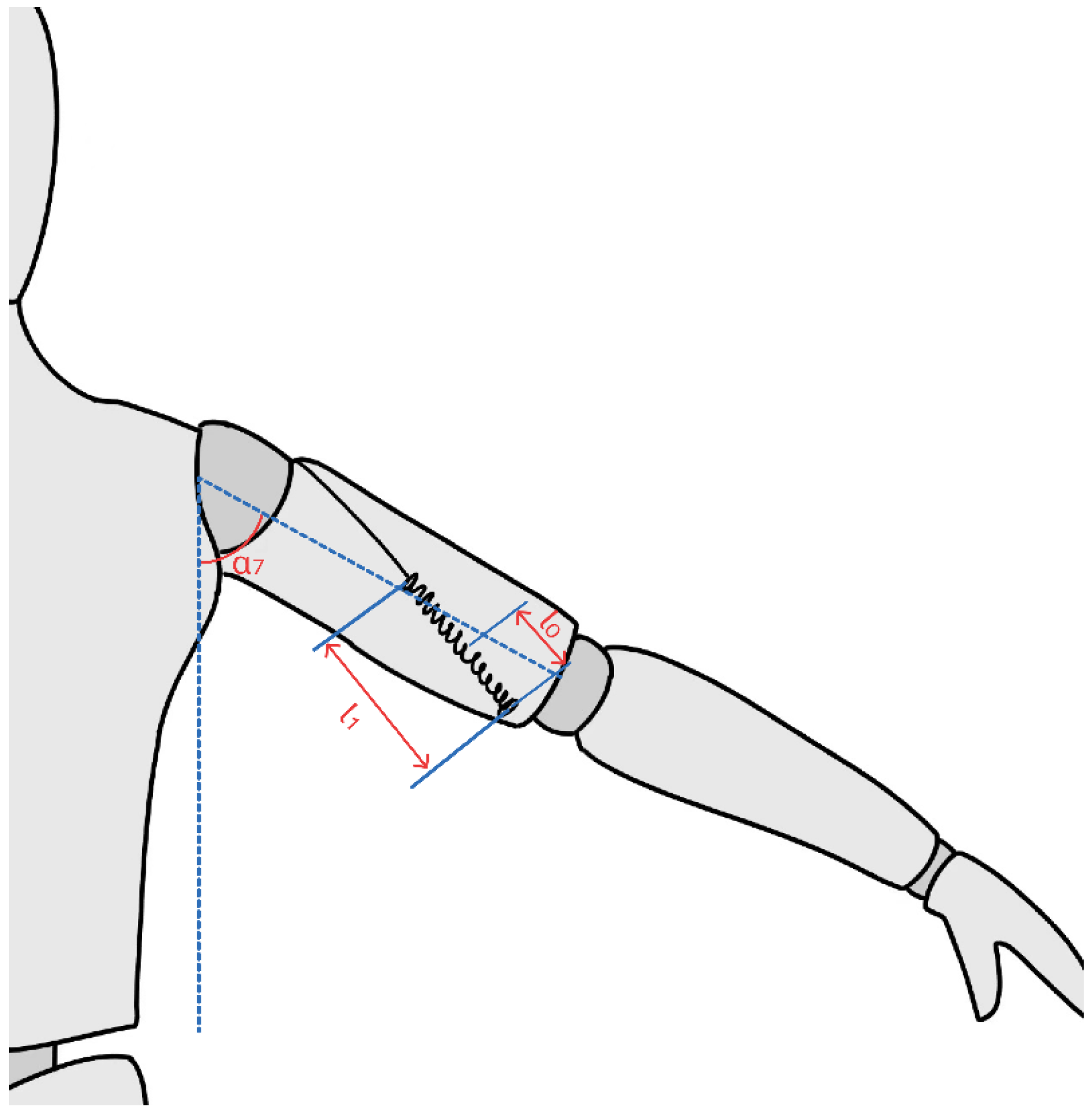
4.1.1. Spring Analysis for the Upper Arm Section

Since the wire driving the upper arm during the rehabilitation motion of external/internal rotation of the shoulder joint remains in close contact with the surface of the upper arm, similar to muscle fibers, the spring selection for the upper arm section should aim to simulate the stretching and contraction motion of human muscle fibers.
The weights of the palm, forearm, and upper arm are as follows [12]:
G 1 = 0.4 kg × g , G 2 = 1.12 kg × g , G 3 = 1.89 kg × g
The total weight of the entire arm is as follows:
G T o t a l = G 1 + G 2 + G 3 = 3.41 kg × g
According to the spring stiffness coefficient formula:
F = l × k
Since the elasticity of human muscle fibers is quantified using Young’s modulus, where muscle elongation is denoted as ∆l, the physiological cross-sectional area of the muscle fibers is represented by s, the original length of the muscle fibers is L, and Young’s modulus is E. Therefore, based on Young’s modulus formula:
F = E × l × s L
Combining the two formulas, we obtain the expression for the spring constant (k) in terms of Young’s modulus (E):
k = E × s L
In the tense state, the Young’s modulus value of the biceps brachii muscle [17] is (123.658 ± 31.392) kPa, whereas, in the relaxed state, the Young’s modulus value is (45.658 ± 13.479) kPa. Since the forearm of this exoskeleton remains taut while driving the upper arm during external/internal rotation rehabilitation movements, we choose the maximum Young’s modulus value from the tense state of the biceps brachii muscle as the reference. Therefore:
E = 155.05 k p a
From [4], it is known that the length of the biceps brachii tendon is 98.1 mm and its width is 21.5 mm. Therefore, for designing the spring stiffness coefficient of this product, we choose these two parameters as reference values. Hence:
L L e n g t h = 98.1 m m , d W i d t h = 21.5 m m
Here, we approximate the physiological cross-sectional area of the biceps brachii muscle as a circle, with π taken as 3.14. Therefore, the cross-sectional area of the biceps brachii muscle is:
s = 1 4 π d W i d t h 2 = 3.63 c m 2
Substituting the values of (s), (E), and (L) into the formula for the spring constant (k), we obtain:
k = 5.2
In summary, the spring responsible for driving the upper arm during external/internal rotation rehabilitation movements is connected to a wire with a spring constant chosen as k = 5.2

4.1.2. Spring Analysis for the Forearm Section

Due to the angle formed between the driving wire of the forearm and the arm during elbow flexion/extension rehabilitation movements, there is no need to mimic muscle fiber elasticity when designing forearm spring parameters; reasonable values will suffice.
Due to the distance of 12 cm from the fixed point of the forearm tension to the elbow joint, the sum of the spring’s original length and its extension should not exceed the length of b.
Therefore, the spring’s original length is:
l 0 f o r e a r m = 3 c m
The spring stiffness coefficient K f o r e a r m is determined as follows:
K f o r e a r m = 4

4.2. Feature Matching

The limiter, wire, and spring form a structure similar to a pulley. The spring’s extension gradually increases under the tension force exerted by the wire. The spring can no longer extend further when it reaches the limiter height. This effectively prevents the wire from causing excessive arm extension, which could lead to joint reversal injury. While ensuring user safety, the product must also promote rehabilitation. Therefore, the limiter’s installation position must allow for the rotational angle range of the arm around the shoulder joint during external/internal rotation rehabilitation. Additionally, it should prevent joint reversal even if there are issues with the equipment control system. Thus, determining the limiter’s position involves calculating the maximum spring extension for driving arm movement.
Through kinematic analysis of the forearm’s external/internal rotation movement around the shoulder joint, the spring extension amount is determined to be:
l = G T o t a l × sin 7 k × cos 5
When α 7 = 90 ° , the spring’s extension is maximum and sin α 7 = 1 ; therefore:
l m a x = G T o t a l k × cos 5
From the kinematic analysis, static analysis of the upper arm, and spring selection, it can be inferred that:
k = 5.2 , G T o t a l = 3.41 k g × g , cos α 5 = 1 2
Therefore, we can conclude:
l m a x = 13 c m
Given that the spring’s original length is 10 cm and the arm length of an adult male with a height of 175 cm falls within the range of 28 to 32 cm, as shown in Figure 12, the limiter should be positioned at the shoulder area of the lightweight upper limb wearable rehabilitation exoskeleton.

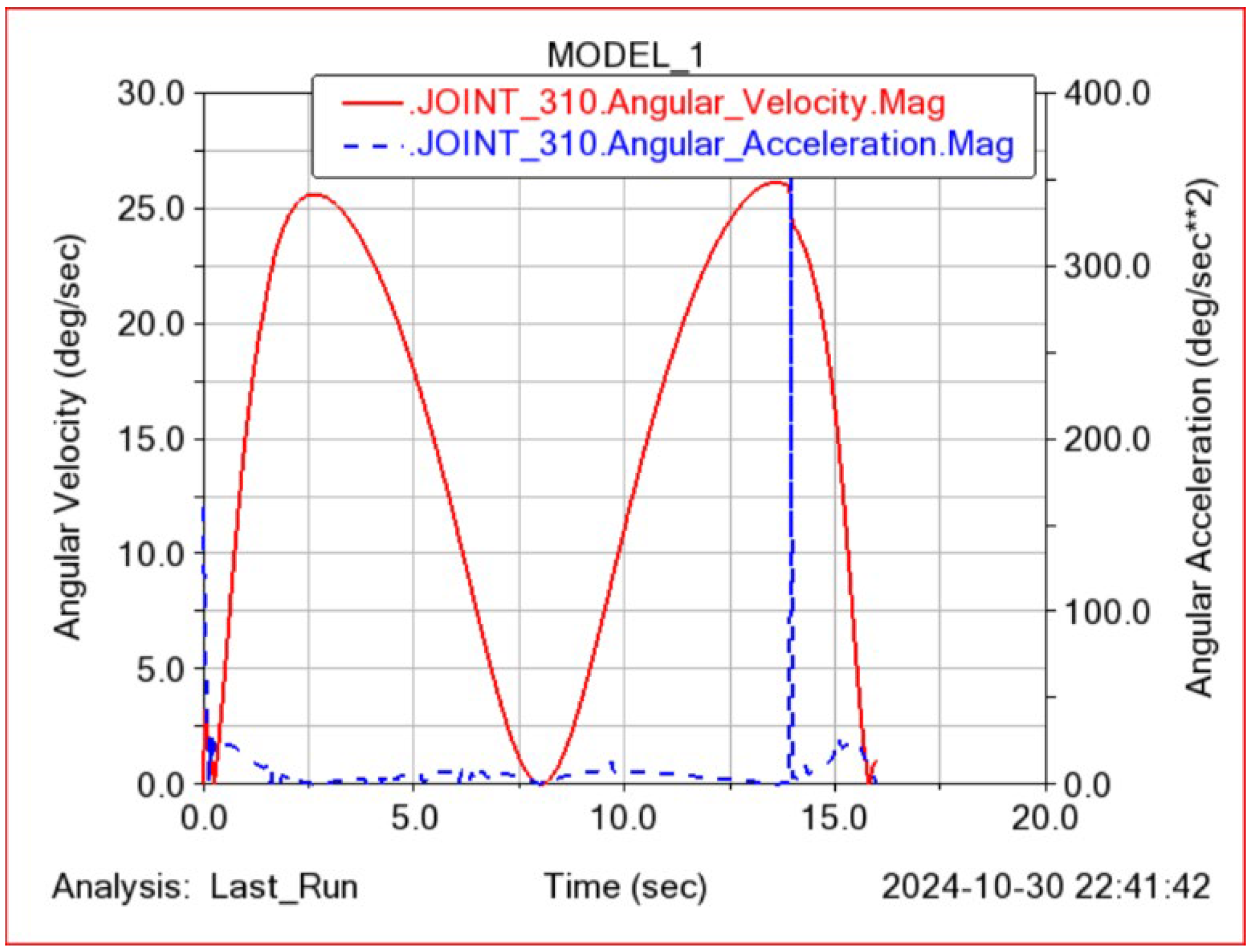
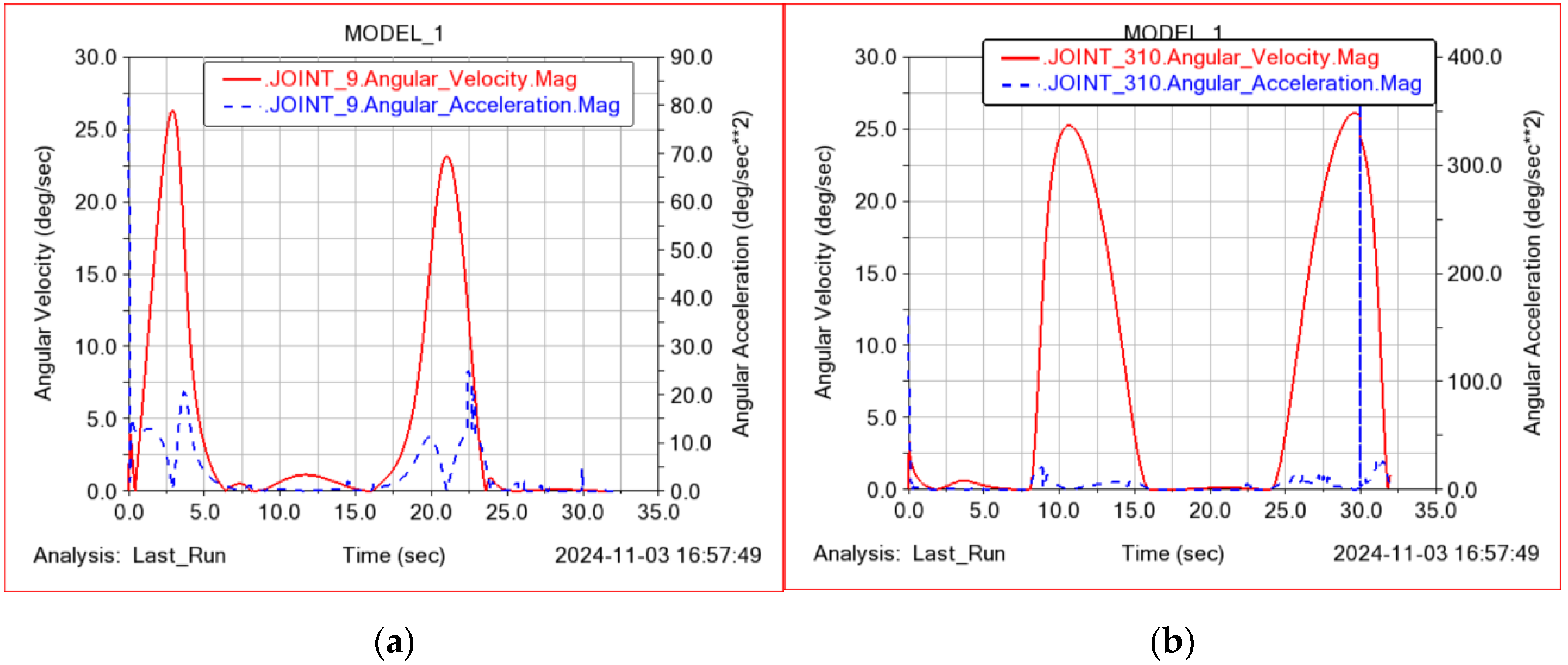
5. Dynamics Simulation

The exoskeleton structure designed in this paper uses steel wires for force transmission, which may exhibit some nonlinear changes during rehabilitation training. These changes could negatively impact the rehabilitation process, such as causing instability in the patient’s movement trajectory or uneven force transmission. Therefore, after conducting structural design, modeling, and kinematic and static analysis of the conceptual rehabilitation exoskeleton, this paper uses ADAMS™ to perform dynamic simulation of the designed rehabilitation robotic arm [18]. The simulation mainly focuses on three rehabilitation modes for patients using the exoskeleton for rehabilitation training. In addition to the internal and external rotation of the shoulder joint and the flexion/extension of the elbow joint, it also considers the co-ordinated rehabilitation training of the upper arm and forearm. This means that, during the internal/external rotation of the shoulder joint, the flexion/extension of the elbow joint is performed simultaneously, thereby assisting patients in restoring the movement capabilities of the upper arm and forearm, as well as their co-ordinated movement abilities. The main method to verify and test whether the exoskeleton-assisted rehabilitation training is stable and safe is through the curves of angular velocity/angular acceleration of the shoulder and elbow joints over time.

5.1. Parameter Setting

In the simulation process, the duration of the shoulder joint’s internal/external rotation and the elbow joint’s flexion/extension movements were both set to 16 s, with 500 steps. For the compound movement training, which combines the movements of the shoulder and elbow joints, the total duration was set to 32 s, with 1000 steps. To make the simulation results more realistic, according to Table 2, the masses of the upper arm, forearm, and hand in the 3D human model were set to 1.89 kg, 1.12 kg, and 0.4 kg, respectively. According to Table 3, the spring stiffness coefficient for the upper arm k1 was set to 5.2 and, for the forearm k 2 , it was set to 4. In order to intuitively demonstrate the stability, safety, and effectiveness of the designed exoskeleton in rehabilitation training, the angular velocity and angular acceleration curves of each rehabilitation action after each simulation are displayed on the same time axis. It is important to note that, due to the different units of angular velocity and angular acceleration, the specific values represented by each unit cell on the vertical axis are also different for angular velocity and angular acceleration. The left axis of the image represents angular velocity, while the right axis represents angular acceleration.

5.2. Simulation of Shoulder Joint Internal/External Rotation Movements

During the simulation of the internal and external rotation of the shoulder joint, the other joints of the human model are set to remain stationary. Only the internal/external rotation of the shoulder joint is set with the step function as follows:
s t e p t i m e , 0 , 0 , 8 , 90 d + s t e p t i m e , 8 , 0 , 16 , 90 d
This step function describes the angular changes of the human shoulder joint during the simulation. s t e p ( t i m e , 0 , 0 , 8 , 90 d ) indicates that the shoulder joint rotates from 0 degrees to 90 degrees over the time interval from 0 to 8 s. Meanwhile, s t e p ( t i m e , 8 , 0 , 16 , 90 d ) indicates that the shoulder joint gradually returns from 90 degrees to 0 degrees over the time interval from 8 to 16 s.
After simulating the internal/external rotation of the shoulder joint, we can obtain the relationship curves of angular velocity/angular acceleration over time, as shown in Figure 13. Point 9 represents the shoulder joint.
From Figure 13, we can see that, during the simulation, the angular velocity and angular acceleration of the shoulder joint generally change steadily and slowly, with no significant abrupt changes. However, at the beginning of the movement, the angular acceleration exhibits a slight abrupt change, indicating a small tremor in the system at the start of the rehabilitation training. Overall, the dynamic simulation verifies that the exoskeleton designed in this paper provides smooth and reasonable movement while assisting patients in the internal/external rotation rehabilitation training of the shoulder joint.

5.3. Simulation of Elbow Joint Flexion/Extension Movements

During the simulation of flexion/extension movements of the elbow joint, the other joints of the human model are set to remain stationary and the step function is applied to the flexion/extension movements of the elbow joint as follows:
s t e p t i m e , 0 , 0 , 8 , 90 d + s t e p t i m e , 8 , 0 , 16 , 90 d
This step function describes the angular changes of the human elbow joint during the simulation. s t e p ( t i m e , 0 , 0 , 8 , 90 d ) indicates that the elbow joint rotates from 0 degrees to 90 degrees over the time interval from 0 to 8 s. Meanwhile, s t e p ( t i m e , 8 , 0 , 16 , 90 d ) indicates that the elbow joint gradually returns from 90 degrees to 0 degrees over the time interval from 8 to 16 s.
After simulating the flexion/extension movements of the elbow joint, we can obtain the relationship curves of angular velocity/angular acceleration with time, as shown in Figure 14. Point310 represents the elbow joint.
From Figure 14, we can see that, during the simulation, the overall curves of the rotational angular velocity and angular acceleration of the elbow joint change smoothly and gradually. There is a noticeable sudden change in acceleration between t = 14 and t = 15. Although there are sudden changes, they are only momentary. Subsequent optimization of the transmission equipment can reduce these sudden changes. The curves show that the exoskeleton’s assistive design for the patient’s elbow joint flexion and extension movements is reasonable.

5.4. Simulation of Combined Rehabilitation Movements of the Shoulder and Elbow Joints

After simulating the rehabilitation movements of the shoulder and elbow joints separately, this paper further analyzes the simulation of the combined movements of the shoulder and elbow joints. Specifically, during the internal and external rotation movements of the shoulder joint, the elbow joint simultaneously performs flexion/extension movements. This combined movement can enhance the co-ordination between the patient’s upper arm and forearm and effectively increase the muscle area of the arm that can be trained by the rehabilitation exercises. During the simulation of the combined movements, the step function for the internal/external rotation movements of the shoulder joint is as follows:
s t e p t i m e , 0 , 0 , 8 , 90 d + s t e p t i m e , 16 , 0 , 24 , 90 d
This step function indicates that between t = 0 and t = 8, the shoulder joint of the human model rotates from 0 degrees to 90 degrees under the guidance of the exoskeleton. Between t = 16 and t = 24, the exoskeleton gradually reduces the pulling force and, under the influence of gravity, the shoulder joint returns from 90 degrees to 0 degrees.
The step function for the flexion/extension movements of the elbow joint is as follows:
s t e p t i m e , 8 , 0 , 16 , 90 d + s t e p t i m e , 24 , 0 , 32 , 90 d
This step function indicates that, between t = 8 and t = 16, the elbow joint of the human model rotates from 0 degrees to 90 degrees under the guidance of the exoskeleton. Between t = 24 and t = 32, the exoskeleton gradually reduces the pulling force and, under the influence of gravity, the elbow joint returns from 90 degrees to 0 degrees.
In the simulation process of combined rehabilitation movement, the curves of the angular velocity and angular acceleration of the shoulder joint over time are shown in Figure 15a, and the curves of the angular velocity and angular acceleration of the elbow joint over time are shown in Figure 15b.
From Figure 15, it can be seen that, during the composite rehabilitation training, the angular velocity and angular acceleration of the shoulder and elbow joints generally change smoothly and do not interfere with each other. This proves the effectiveness and safety of the composite rehabilitation exercise designed in this study. However, at t = 30 s, there is a significant mutation in the angular acceleration of the elbow joint, and further experiments and investigations are needed to determine the specific cause of this mutation.

6. Discussion

The rehabilitation exoskeleton system designed in this paper has the following advantages compared to the existing exoskeleton systems on the market:
(1)
Using flexible materials and motor-driven steel wires ensures that the exoskeleton system is lighter in weight, thereby reducing the burden on patients during rehabilitation.
(2)
It significantly reduces the production cost of the exoskeleton.
(3)
The limiter designed in this paper improves the safety of the exoskeleton system.
(4)
This portable exoskeleton system allows patients to perform rehabilitation training in any scenario.
(5)
The human-body-conforming structural design ensures the rehabilitation effect for patients of different body types.
However, this exoskeleton system also faces the following issues:
(1)
The arrangement of steel wires on the arm may lead to unpredictable nonlinear changes, resulting in a significant difference between the actual rehabilitation effect and theoretical analysis.
(2)
The lifespan of the soft exoskeleton is relatively short.
In the subsequent research, we will mainly address these two issues to improve and optimize the exoskeleton system. Additionally, we will combine deep learning to design an intelligent control system based on EEG and EMG signals.

7. Conclusions

This paper addresses the limitations of existing wearable rehabilitation exoskeleton systems, which predominantly rely on rigid exoskeleton designs. These rigid systems suffer from issues such as excessive weight, insufficient flexibility, complex structures, and safety concerns. To overcome these challenges, we propose a flexible wearable rehabilitation exoskeleton that utilizes elastic fabric materials as the primary component. The system is driven by a combination of electric motors, wires, and springs. Notable features of this exoskeleton include:
(1)
The flexible wearable robot utilizes elastic fiber fabric as its main structure. The exoskeleton system significantly reduces its overall weight compared to rigid exoskeletons.
(2)
Designed for patients with upper limb movement disorders, the robot features three degrees of freedom: elbow flexion/extension, shoulder flexion/extension, and shoulder internal/external rotation.
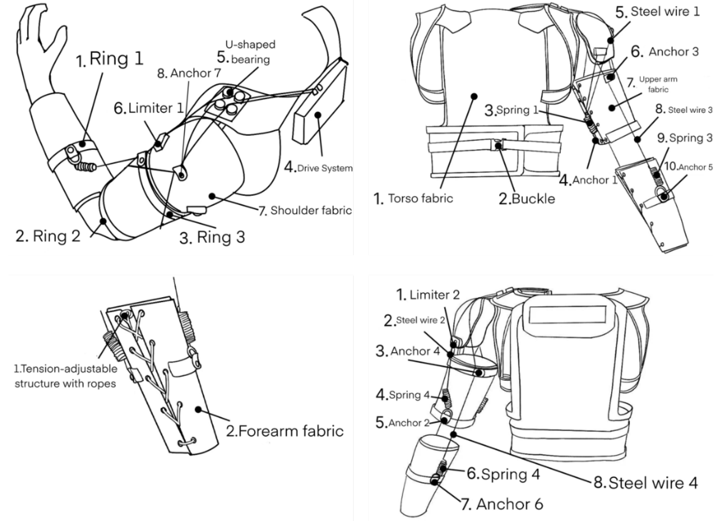
(3)
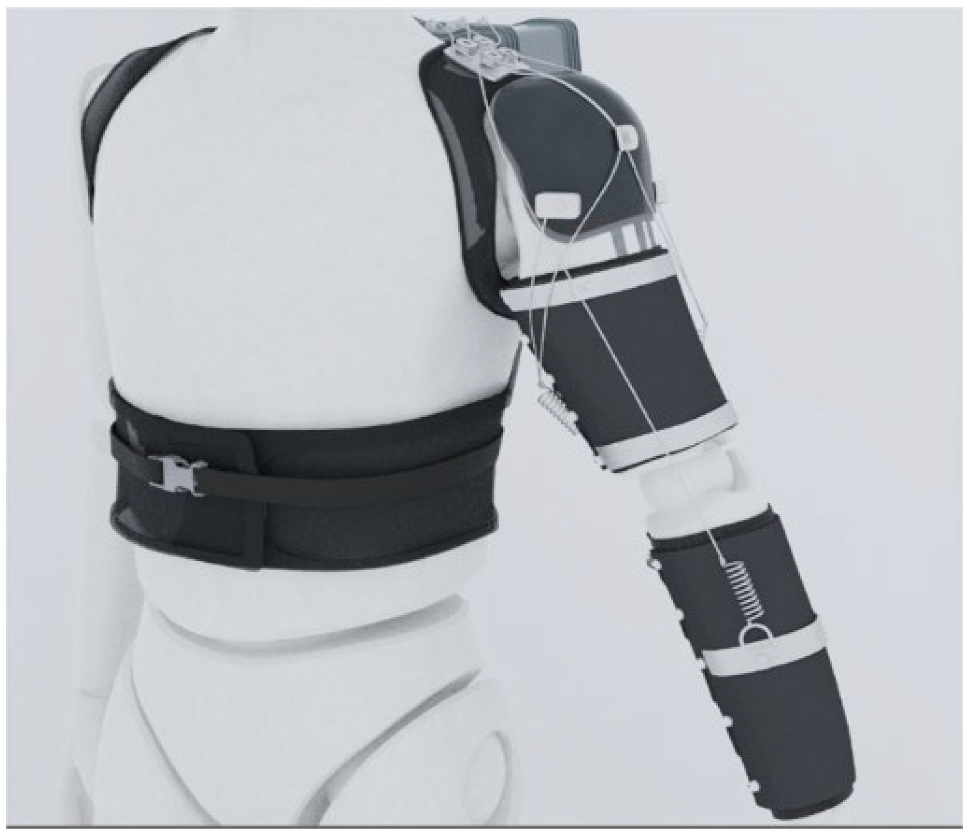
In both the upper arm and forearm fabric, there are sewn on three alloy rings that serve as fixed anchor points for connecting the driving wires. One ring is sewn onto the middle section of the forearm fabric, while the other two are positioned at the upper and lower edges of the upper arm fabric. The alloy rings at the upper edges of the forearm and upper arm fabric are used to secure the wires driving forearm movements, while the alloy ring at the lower edge of the upper arm fabric is used to secure the wires driving upper arm movements.
(4)
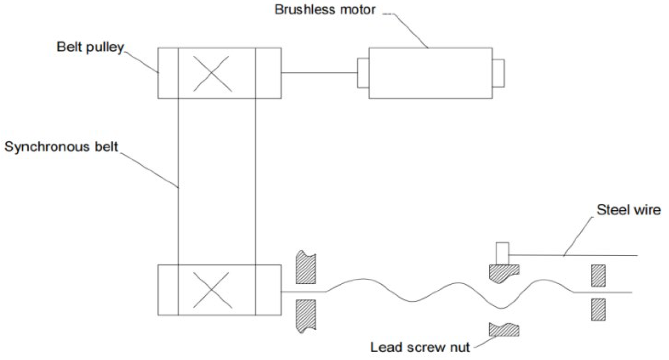
The drive unit is mounted on the back and controlled by a motor to stretch the wires, simulating human upper limb movements.
(5)
By integrating the trunk–shoulder–upper arm fabric into one unit and keeping the forearm fabric separate, this flexible upper limb rehabilitation robot isolates the rehabilitation movements of each joint. Steel wires connect the drive unit to various components of the robot, transmitting the driving force and enabling rehabilitation movements across the arm joints, resulting in consistent human–robot motion. Rehabilitation exercises can be tailored to individual patients based on their specific needs and joint conditions, leading to effective rehabilitation outcomes.
(6)
The special elastic cord tension structure used in both the upper arm and forearm fabric ensures secure and adjustable attachment to different body sizes.
(7)
Springs connect the driving wires to the fabric, providing greater flexibility and cushioning for patient rehabilitation.
(8)
A layer of silicone material is sewn onto the inner side of the upper arm and lower arm fabric. Using silicone as the inner layer structure increases the friction between the exoskeleton device and the user’s arm. This effectively prevents the occurrence of sliding of the fabric up and down during the driving process.
After detailed structural design, this paper also conducted a simple kinematic and static analysis of the designed exoskeleton system. Based on the kinematic and static analysis, the selection of springs was carried out, and the positions of the limiters were specified. Finally, this paper used ADAMS™ to perform dynamic simulation of the designed exoskeleton system. The relationship curves of joint angular velocity/acceleration with time during rehabilitation training obtained through simulation further demonstrated the rationality and stability of the designed exoskeleton system. Modeling and visualization of the lightweight wearable rehabilitation exoskeleton is shown in Figure 16. The current kinematic and static analyses still have significant limitations, with the kinematic analysis currently limited to position analysis. At the same time, the current dynamic simulation can only demonstrate the effectiveness and feasibility of the design in the rehabilitation training process. The issues of nonlinear changes in the cables used and the simulation of the control system need to be further explored and refined in future work. In our future work, we will first conduct more detailed and complex mathematical analysis. Based on this mathematical analysis, we will perform co-simulation and control simulation of the rehabilitation exoskeleton. After completing the physical model, we will analyze the cables on the actual machine to further evaluate the durability, strength, and practical effects of the exoskeleton.
In future research, I plan to further design a force–position hybrid control system model for the exoskeleton system. At the same time, I will attempt to detect human bioelectrical signals [19] through deep learning methods to identify human movement intentions. This will enhance the automation level of the exoskeleton system, providing greater convenience for the postoperative rehabilitation of stroke patients.

Author Contributions

Conceptualization, X.J., W.D. and Y.W.; methodology, X.J. and W.D.; software, X.J. and Q.L.; validation, X.J.; formal analysis, X.J.; investigation, W.D. and W.Y.; data curation, W.D. and Y.Y.; writing—original draft preparation, X.J. and M.B.; writing—review and editing, X.J. and M.B.; supervision, Y.W.; All authors have read and agreed to the published version of the manuscript.

Funding

This research received no external funding.

Institutional Review Board Statement

Not applicable.

Informed Consent Statement

Not applicable.

Data Availability Statement

All data generated or analysed during this study are included in this published article.

Acknowledgments

This article is a revised and expanded version of a paper entitled ‘Mechanical Design and Analysis of a Cable-Driven Wearable Flexible Exoskeleton System’ [20], which was presented at 2024 2nd International Conference on Precision Engineering and Mechanical Manufacturing (PEMM 2024), Inha University, Incheon, Republic of Korea, during 1–3 August 2024.

Conflicts of Interest

The authors declare no conflict of interest.

References

  1. Reshetnyak, E.; Ntamatungiro, M.; Pinheiro, L.C.; Howard, V.J.; Carson, A.P.; Martin, K.D.; Safford, M.M. Impact of multiple social determinants of health on incident stroke. Stroke 2020, 51, 2445–2453. [Google Scholar] [CrossRef] [PubMed]
  2. Yu, C. Orthopedic Rehabilitation; People’s Medical Publishing House: Beijing, China, 2010; pp. 152–187. [Google Scholar]
  3. Liu, G.; Ji, X. Human Factors Engineering; Peking University Press: Beijing, China, 2012; pp. 101–114. [Google Scholar]
  4. Schwarz, A.; Bhagubai, M.M.; Wolterink, G.; Held, J.P.; Luft, A.R.; Veltink, P.H. Assessment of upper limb movement impairments after stroke using wearable inertial sensing. Sensors 2020, 20, 4770. [Google Scholar] [CrossRef] [PubMed]
  5. Borschmann, K.N.; Hayward, K.S. Recovery of upper limb function is greatest early after stroke but does continue to improve during the chronic phase: A two-year, observational study. Physiotherapy 2020, 107, 216–223. [Google Scholar] [CrossRef] [PubMed]
  6. Yu, X.; Xu, Z.; Shi, J.; Zhang, F. Development of Upper-Limb Wearable Exoskeleton Robot. In Proceedings of the 2nd International Conference on Artificial Intelligence and Advanced Manufacture, Manchester, UK, 15–17 October 2020; ACM: New York, NY, USA, 2020; pp. 434–439. [Google Scholar]
  7. Li, N.; Yu, P.; Yang, T.; Zhao, L.; Liu, Z.; Xi, N.; Liu, L. Bio-inspired wearable soft upper-limb exoskeleton robot for stroke survivors. In Proceedings of the 2017 IEEE International Conference on Robotics and Biomimetics (ROBIO), Macau, Macao, 5–8 December 2017; IEEE: New York, NY, USA, 2017; pp. 2693–2698. [Google Scholar]
  8. Ponomarenko, Y.; Aubakir, B.; Hussain, S.; Shintemirov, A. An end-effector based upper-limb rehabilitation robot: Preliminary mechanism design. In Proceedings of the 2014 10th France-Japan/8th Europe-Asia Congress on Mecatronics (MECATRONICS2014-Tokyo), Tokyo, Japan, 27–29 November 2014; pp. 168–172. [Google Scholar] [CrossRef]
  9. Liu, Y.; Guo, S.; Hirata, H.; Ishihara, H.; Tamiya, T. Development of a powered variable-stiffness exoskeleton device for elbow rehabilitation. Biomed. Microdevices 2018, 20, 64. [Google Scholar] [CrossRef] [PubMed]
  10. Velez-Guerrero, M.A.; Callejas-Cuervo, M.; Mazzoleni, S. Design, development, and testing of an intelligent wearable robotic exoskeleton prototype for upper limb rehabilitation. Sensors 2021, 21, 5411. [Google Scholar] [CrossRef] [PubMed]
  11. Grasgruber, P.; Hrazdíra, E. Nutritional and socio-economic predictors of adult height in 152 world populations. Econ. Hum. Biol. 2020, 37, 100848. [Google Scholar] [CrossRef] [PubMed]
  12. Cao, K. Design and Performance Testing of a Flexible Wearable Upper Limb Power Suit. Master’s Thesis, Yanshan University, Qinhuangdao, China, 2019. [Google Scholar] [CrossRef]
  13. Sun, X. Research on a Soft Wearable Exoskeleton System for Upper Limb Rehabilitation. Master’s Thesis, Harbin Institute of Technology, Harbin, China, 2019. [Google Scholar] [CrossRef]
  14. Nef, T.; Guidali, M.; Klamroth-Marganska, V.; Riener, R. ARMin-exoskeleton robot for stroke rehabilitation. In Proceedings of the World Congress on Medical Physics and Biomedical Engineering, Munich, Germany, 7–12 September 2009; Volume 25/9 Neuroengineering, Neural Systems, Rehabilitation and Prosthetics. Springer: Berlin/Heidelberg, Germany, 2009. [Google Scholar]
  15. Balasubramanian, S.; Wei, R.; Perez, M.; Shepard, B.; Koeneman, E.; Koeneman, J.; He, J. RUPERT: An exoskeleton robot for assisting rehabilitation of arm functions. In Proceedings of the 2008 Virtual Rehabilitation, Vancouver, BC, Canada, 25–27 August 2008; IEEE: New York, NY, USA, 2008. [Google Scholar]
  16. Kim, H.; Rosen, J. Predicting redundancy of a 7 dof upper limb exoskeleton toward improved transparency between human and robot. J. Intell. Robot. Syst. 2015, 80, 99–119. [Google Scholar] [CrossRef]
  17. Wen, C.; Fan, C.; An, L.; Chen, H.; Wang, Y.; Tang, J. Real-time quantitative ultrasound elastography for detecting differences in the elastic modulus of the biceps brachii muscle under relaxed and tense states. Chin. J. Med. Ultrasound (Electron. Ed.) 2011, 8, 129–134. [Google Scholar]
  18. Gull, M.A.; Bak, T.; Bai, S. Dynamic modeling of an upper limb hybrid exoskeleton for simulations of load-lifting assistance. Proc. Inst. Mech. Eng. Part C J. Mech. Eng. Sci. 2022, 236, 2147–2160. [Google Scholar] [CrossRef]
  19. Mekruksavanich, S.; Jitpattanakul, A. Exercise Activity Recognition with Surface Electromyography Sensor using Machine Learning Approach. In Proceedings of the 2020 Joint International Conference on Digital Arts, Media and Technology with ECTI Northern Section Conference on Electrical, Electronics, Computer and Telecommunications Engineering (ECTI DAMT & NCON), Pattaya, Thailand, 11–14 March 2020; pp. 75–78. [Google Scholar] [CrossRef]
  20. Jin, X.; Ding, W.; Li, Q.; Yang, W.; Wei, Y. Mechanical Design and Analysis of a Cable-Driven Wearable Flexible Exoskeleton System. In Proceedings of the 2024 2nd International Conference on Precision Engineering and Mechanical Manufacturing (PEMM 2024), Inha University, Incheon, Republic of Korea, 7–9 August 2024. [Google Scholar]
Figure 1. Conceptual design of lightweight upper limb wearable rehabilitation exoskeleton.
Technologies 12 00238 g001
Figure 2. U-shaped bearing for adjusting wire tension.
Technologies 12 00238 g002
Figure 3. Conceptual design of lightweight upper limb wearable rehabilitation exoskeleton: three views and tension-adjustable structure with ropes.
Technologies 12 00238 g003
Figure 4. Design of limiter structure.
Technologies 12 00238 g004
Figure 5. Schematic diagram of the driving system.
Technologies 12 00238 g005
Figure 6. The kinematic analysis diagram 1 of the upper arm’s external/internal rotation concerning the shoulder joint.
Technologies 12 00238 g006
Figure 7. The kinematic analysis diagram 2 of the upper arm’s angle of external/internal rotation concerning the shoulder joint.
Technologies 12 00238 g007
Figure 8. The kinematic analysis diagram 1 of the forearm’s flexion/extension movements concerning the elbow joint.
Technologies 12 00238 g008
Figure 9. The kinematic analysis diagram 2 of the forearm’s flexion/extension movements concerning the elbow joint.
Technologies 12 00238 g009
Figure 10. The force analysis diagram of the upper arm’s external/internal rotation movements concerning the shoulder joint.
Technologies 12 00238 g010
Figure 11. The force analysis diagram of the forearm’s flexion/extension movements concerning the elbow joint.
Technologies 12 00238 g011
Figure 12. Positioning diagram for limiter.
Technologies 12 00238 g012
Figure 13. The relationship curves of angular velocity/angular acceleration of the shoulder joint with respect to time in the simulation of shoulder joint internal/external rotation.
Technologies 12 00238 g013
Figure 14. The relationship curves of angular velocity/angular acceleration of the elbow joint with respect to time in the simulation of elbow joint flexion/extension.
Technologies 12 00238 g014
Figure 15. (a): The relationship curves of angular velocity/angular acceleration of the shoulder joint with respect to time in compound movements. (b): The relationship curves of angular velocity/angular acceleration of the elbow joint with respect to time in compound movements.
Technologies 12 00238 g015
Figure 16. Modeling and visualization of lightweight wearable rehabilitation exoskeleton.
Technologies 12 00238 g016
Table 1. Maximum range of motion of upper limb joints.
JointActionMaximum Range of Motion (°)Functional Range (°)
shoulder jointexternal/internal rotation0~900~80
elbow jointflexion/extension0~1500~120
Table 2. Human upper limb parameters table.
Parameter EstimationStandard Parameter
Upper arm length (mm)336----
Upper arm circumference (mm)58/40----
Upper arm quality (kg)2.681.89
Forearm length (mm)260----
Forearm circumference (mm)45/27----
Forearm quality (kg)1.351.12
Palm quality (kg)0.50.4
Palm center5050
Table 3. Specific parameters of lightweight wearable upper limb rehabilitation exoskeleton.
Upper ArmForearm
ParameterValueParameterValue
L128 cmL418 cm
h120 cmh320 cm
d11 cmd31 cm
L226 cmL516 cm
h22 cmh42 cm
d20.5 cmd40.5 cm
b20 cmL63 cm
L310 cmk24
k15.2a12 cm
R10.25 cmR20.25
x14.75 cmx34.75 cm
x20.5 cmx40.5 cm
Table 4. Lightweight comparison of upper limb rehabilitation exoskeleton systems.
LightweightDriving Mechanism
The exoskeleton designed in this paper2.5–3 kgmotor drive
ARMin IV14 kgmotor drive
RUPERT10 kgpneumatic muscle drive
UL-EXO712 kgmotor drive
Disclaimer/Publisher’s Note: The statements, opinions and data contained in all publications are solely those of the individual author(s) and contributor(s) and not of MDPI and/or the editor(s). MDPI and/or the editor(s) disclaim responsibility for any injury to people or property resulting from any ideas, methods, instructions or products referred to in the content.

