Article

Design and Implementation of an Anthropomorphic Robotic Arm Prosthesis

by
Valentina A. Yurova
1,2,*,
Gleb Velikoborets
1,3 and
Andrei Vladyko
1
1
Faculty of Fundamental Training, The Bonch-Bruevich Saint Petersburg State University of Telecommunications, 193232 Saint Petersburg, Russia
2
Department of Medical Informatics and Physics, North-Western State Medical University named after I.I. Mechnikov (NWSMU), 195067 Saint Petersburg, Russia
3
Design Department, Federal Scientific Center of Rehabilitation of the Disabled named after G.A. Albrecht, 195067 Saint Petersburg, Russia
*
Author to whom correspondence should be addressed.
Technologies 2022, 10(5), 103; https://doi.org/10.3390/technologies10050103
Submission received: 30 July 2022 / Revised: 12 September 2022 / Accepted: 15 September 2022 / Published: 21 September 2022
(This article belongs to the Special Issue 10th Anniversary of Technologies—Recent Advances and Perspectives)

Abstract

:
The development and manufacture of prosthetic limbs is one of the important tendencies of the development of medical techniques. Taking into account the development of modern electronic technology and automated systems and its mobility and compactness, the actual task is to create a prosthesis that will be close to a fully functioning human limb in its anthropomorphic properties and will be capable of reproducing its basic actions with a high accuracy. The paper analyzes the main directions in the development of a control system for electronic limb prostheses. The description and results of the practical implementation of a prototype of an anthropomorphic prosthetic arm and its control system are presented in the paper. We developed an anthropomorphic multi-finger artificial hand for utilization in robotic research and teaching applications. The designed robotic hand is a low-cost alternative to other known 3D printed robotic hands and has 21 degrees of freedom—4 degrees of freedom for each finger, 3 degrees for the thumb and 2 degrees responsible for the position of the robotic hand in space. The open-source mechanical design of the presented robotic arm has mass-dimensional and motor parameters close to the human hand, with the possibility of autonomous battery operation, the ability to connect different control systems, such as from a computer, an electroencephalograph, a touch glove.

1. Introduction

Robotic arms are widely used in different fields: remote manipulation of objects in unsafe conditions [1,2], industry [3,4], and surgery [5]. One of the broad areas of application is prosthesis. Robotic prostheses give people back the ability to interact with the world around them. However, most of the prostheses that are used in modern rehabilitation do not fully provide users with these abilities. They allow people without arms to perform simple actions, such as grabbing and holding objects, and some other simple operations.
The major criteria used for the design of the anthropomorphic robotic arm were the number of joints, degrees of freedom, number and type of actuators, weight, and the mobility ranges of each of the finger joints and the hand. This paper presents the possibility of the practical implementation of a low-cost design of an anthropomorphic arm, approximated or improved in properties to available analogues, with the ability to work from various power sources, and with simple controls and connections to various control systems. This will; make the prototype universal for different utilizations in robotics research, design of arm–brain control systems and teaching applications and simplify and make it more ergonomic to connect it to control systems.
The purpose of the work was to design a low-cost, easy-to-maintain anthropomorphic robotic arm prosthesis as close in functionality and mass-dimensional dimensions as possible to a real human hand. The control system of the arm–hand prototype presented in the work was designed so that it could be connected to any control system (such as from a computer, an electroencephalograph, a touch glove, etc.) to expand the possibilities of application in medicine, robotic research and teaching.
The designs of robotic arms that can provide smooth and precise manipulations are called anthropomorphic. Anthropomorphic design implies the presence of a mechanism similar in structure to a human hand (joints and connection tissues). Most of the existing prototypes are under actuated, that is, the number of actuators is less than the number of degrees of freedom (DoF). In previous research, [6,7,8] it was determined that only 1–6 activators are usually contained in constructions of underactuated robotic arms (compared to 34 muscles controlling the human hand).
What problems appear when designing fully actuated mechanisms? The human hand has 27 degrees of freedom: 4 on each finger, 3 for extension and flexion and 1 for extension and compression. The biomechanics of the thumb and wrist are more intricate. The thumb has five degrees of freedom, and for the rotation and movement of the wrist there are six degrees of freedom. Therefore, fully actuated robotic arms imply the presence of a drive mechanism for each of the degrees of freedom. This significantly increases the weight and size characteristics of the structure and its automated control system due to the large number of drives and the choice of their effective placement in the housing.
The results of the investigation of this issue [9] showed that the weight of the prosthetic hand should be no more than 500 g, based on patient feedback. This corresponds to the data in [10] about the average weight of the body segment, where the average arm weight (men and women) was 580 g. Based on [10] data about the average weight of the body segment, the average weight of the forearm is about 3 times the average weight of the hand. Therefore, using the Chappel limit of 500 g as an ideal reference point for limiting the weight of the prosthesis, the forearm should weigh less than 1.5 kg (if it is included in the design at all) in the design of anthropomorphic constructions.
In the work in [11], the modern existing designs of upper limb prostheses were investigated. From their data, it can be concluded that most of robotic arm constructions are insufficiently equipped (on average four actuators per 10 DoF). Such a DoF/actuators ratio does not allow a user with a lost limb to make up for the entire range of movement that was previously available to him.
Taking into account the growing need for electronically controlled robotics systems in various fields of technology and rehabilitation medicine, the aim of the work was to design and create an experimental prototype of a multi-functional anthropomorphic robotic arm with the possibility of using it as a manipulator and prosthesis of a lost limb.
The main stages of our research are presented in the form of a flowchart in Figure 1.
Motivated by the described state-of-art, this work presents the results of the analysis, calculation, design and the practical realization of a working prototype of a robotic anthropomorphic arm–hand with justifications of engineering solutions. The completely independent creation of a working prototype was carried out, which is characterized by a high degree of freedom of movement of individual components in comparison with existing analogues, simplicity and accuracy of the control system and mass and weight dimensions close in parameters to the human hand. Our novel contributions can be summarized as follows:
  • Analyzing the basic requirements for the parameters of an anthropomorphic robotic arm;
  • Designing and developing the anthropomorphic robotic arm and manufacturing and assembling the mechanical parts for construction;
  • The calculation, design and development of the power supply circuits and the control system of the anthropomorphic robotic arm were carried out to ensure the simultaneous control of all drives;
  • Testing the possibilities of connecting to different control systems.
The rest of the article is structured as follows. Section 2 presents the brief analysis of the main directions in the development of robotic arm designs. Section 3 presents the results of the development, manufacture and assembly of the design of the anthropomorphic robotic arm and the data on the mass-dimensional parameters and properties of the mechanical design of the developed prototype of an anthropomorphic robotic arm. Moreover, Section 3 presents the structure of automated and control systems, analysis and calculations of the power supply and control circuits of the robotic anthropomorphic arm. The obtained results and links to video files demonstrating the work of the anthropomorphic robotic arm are presented in Section 4. Finally, the conclusions and future work are presented in Section 5.

2. Related Works

There are many developments of robotic arms, but not all of them fully correspond to anthropomorphic design. In [12,13], the authors developed robotic arms based on the kinematics of the human hand, that is, the most satisfying signs of anthropomorphism, but each of them was underactuated, similar to most other developments of robotic prostheses.
A number of developments, such as in [14,15,16,17], implemented only some parts of the joints of the human hand, with others staying strictly fixed in one position, in particular the MCPjoint, removing its adduction and abduction, leaving only compression and stretching. Each of the developments was also underactuated.
However, most of the developments deviate from anthropomorphic design in order to provide the prosthesis with only the basic movements that are necessary in everyday life. For example, in the studies in [8,18,19], two types of joints were combined, and thus the finger had two phalanges, instead of three.
In other developments [7,20], it was structurally made so that the joints were kinematically connected to each other, which excludes a separate contraction of the phalanges.
The number of DoF and actors of some modern designing robotic arms are shown in Table 1.
Most of the robotic arm–hand designs can be divided into the following groups: finger, hand; arm forearm; and full arm construction up to the shoulder. In the first group, generally, a good reproducibility of movements has been worked out, as close as possible to the real part of the limb. This group is more often used in research to design touch sensors and research systems in relation to the reproducibility of tactile sensations. However, the wrist or the base of the finger (in the case of a design in the form of 1–2 fingers) remains stationary. Less detail and accuracy of reproducing movements, avoiding anthropomorphism, are characteristic of arm–shoulder prosthesis designs. This group uses more complex electrical circuits and electromechanical systems to control and recreate hand movements.

3. Methods

3.1. Prototype Design and Manufacture

Most of the hand parts were 3D printed. Such a solution is increasingly used in many devices, because of a significant reduction in the weight of structures, the simplicity, fast and low cost of manufacture, the possibility of manufacturing variety of shapes, and the high repeatability of the parameters of details, taking into account individual characteristics [14,21,22,23,24]. The latter property is especially relevant for devices used in medicine and rehabilitation. The plastic used in three-dimensional printing is currently characterized by high strength and wear resistance, which explains the possibility of its use in medical devices.
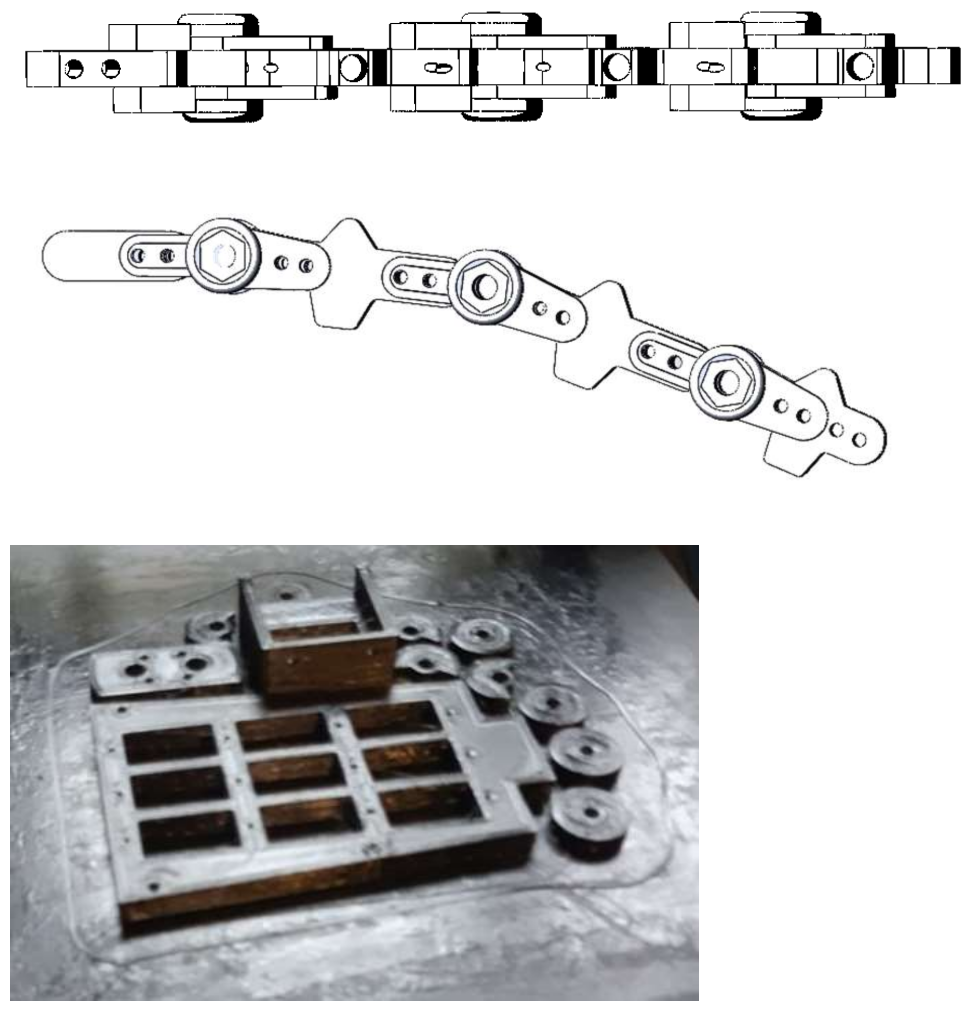
In our prototype of an anthropomorphic robotic arm our goal was to closely copy the properties of the hand rather than its intrinsic structure. Based on the results of the analysis of the biomechanics of the hand, the design of the finger of the robotic arm was developed (Figure 2), in which each phalanx is connected to the next one with springs of twisting.
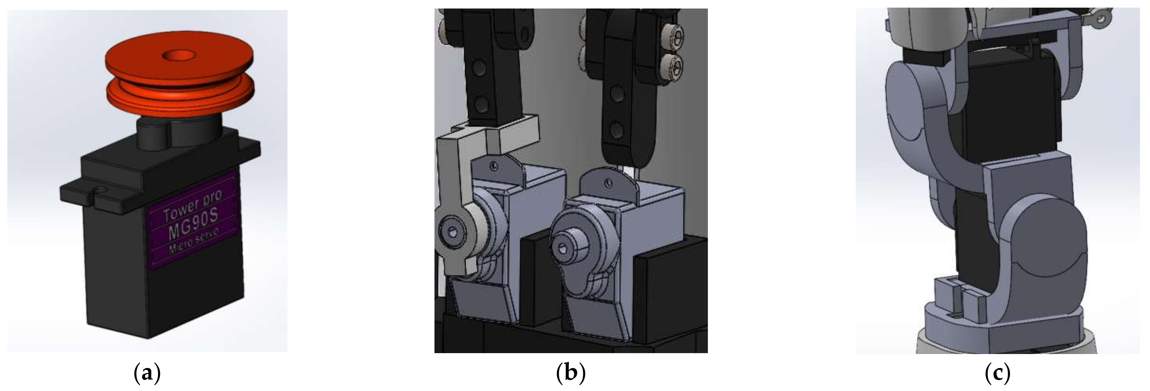
A multiturn winder transfers the rotational gear motion to the tendons. The phalanges are driven by threads attached to servos, as shown in Figure 3a. The servos are located in the forearm. It contains the motor, the position sensors, the wave generator of the harmonic drive gear and the electronics. To reduce the distal phalanges, mg90s servos were used, which provide a compression force of 1.8 kg, and DS–939MG servos were used to reduce the proximal phalanges, which provide a compression force of 2.5 kg. With the help of a disk mounted at the output of the drive gearbox, the rotational motion is converted into linear. In the future, it is planned to use linear actuators to reduce the proximal phalanges, in order to reduce the volume occupied by it.
The movement of the fingers is carried out directly by fixing the base of the finger on the mg995 servo gearboxes installed in the wrist of the robotic arm, as shown in Figure 3b. The wrist part of the robotic arm was made using the mechanism shown in Figure 3c. This inclusion of the servos allows the greatest effort to be developed; the design can withstand loads up to 15 kg.
The wrist was made on the basis of the spherical antiparallelogram mechanism, which provides rotation of the whole hand, combining reliability and simplicity, and allows for sideways motion, flexion and extension of the robotic wrist as a real human wrist [25,26]. The main difference from the designs taken as a basis is that the actuators are placed directly in the wrist joints, which provides maximum reliability and the smallest shoulder of force action, and, as a result, the maximum possible force exerted.
The range of movement of the mechanism for the fingers is shown in Figure 4. The number of servos and the design of the fingers provide controlled flexion and extension of the entire finger and each phalanx separately. The position can be fixed at any angle within the operating limits.
The final view of the developed and assembled forearm and hand of the anthropomorphic robotic prototype is shown in Figure 5.
Taking into account the nominal angular velocity of micromotors, the maximum displacement of the phalanx of fingers and kinematic characteristics, we obtained that the maximum rotation speed was almost 5 rad/s, the response time to the execution of the command of flexion and extension of the phalanx of 90 degrees for this type of movement was less than 400 ms. The range of the finger and wrist movements were comparable with the movement of a human hand [27].

3.2. Control System

When designing the structures of an anthropomorphic robotic arm, the automated control system is crucial to the smooth regulation of actions and the accuracy of their reproduction. The lack of an analytical approach, difficult-to-solve dynamics and inconsistency with standard robotic manipulators are the reasons that reflect the importance of research on the ways of designing and automating an anthropomorphic arm for the next stage in the development of robotic manipulators and anthropomorphic prosthetic arms. To work with it, developments are underway to create control interfaces that differ in the types of signals used (speech, electromagnetic, etc.) and the methods of their processing and transmission for reproducing actions with robotic manipulators or a prosthesis. The typical structure of a control system consists of setting devices and regulators performing algorithms and control methods.
The methods of prosthesis control are based on fundamental principles: open-loop control (without feedback), feedback and compensation. Technical feedback is usually implemented either by the force or by the position. To increase the efficiency of the operations performed, an operator needs to receive more information about the state of the object (for example, about the temperature of the object, the humidity of the surface), that requires extended feedback, which in the vast majority of modern systems has not yet been implemented. The choice of the upper limb prosthesis control system is largely determined by of the type of the master signal. For example, the mechanical movement of arm segments, bioelectric signals of contracting muscles, varying impedance (total resistance) to the alternating current of a contracting muscle can be used as signals.
There is a transition to electromechanical prostheses of lost limbs in rehabilitation medicine. In spite of a great variety of modern technological achievements, the widely used electromechanical prostheses are controlled by means of electrical signals associated with the contraction and relaxation of the forearm muscles [28,29]. The signals are taken by surface electromyography electrodes from two groups of stump muscles (flexors and extensors) and fed through amplifiers to the electromechanical hand control system. The information from the sensors is transmitted to the microprocessor of the robotic hand and through computer algorithms is converted into motor commands and the prosthesis performs a certain gesture or grip. This control system is based on the electromyography and can be used only in the cases of the amputation of a part of a limb (hand and/or forearm), when electrical activity is preserved in intact muscle fibers associated with the control of the missing part.
Another large group of prosthetic control methods are neurocomputer interfaces. A neurocomputer interface is understood as a system that allows neural signals of the brain related to some part of the body, for example, to an arm or leg, to be decoded. There are several competing approaches to the creation of neurocomputer interfaces, which differ in the way electrical signals are transmitted from the brain to the computer. Invasive systems are based on implanting a matrix of ultrathin electrodes into certain areas of the brain [30]. However, the implantation of the electrode matrix requires unsafe surgery. Moreover, the questions remain open about the long-term biocompatibility of the electrode material and brain tissue and the change in work efficiency over time. Currently, the record of life with an invasive brain–computer interface is 7 years and 3 months [31].
Non-invasive systems are based on capturing electrical signals of the brain from the surface of the scalp. They use an electroencephalogram. Electroencephalography (EEG) electrodes that record the brain activity of the operator are used as the method that registers the master signals from a biological object (the operator of the prosthesis) [8]. The control of the prosthesis by this method consists of registering a signal of electrical activity of the brain using surface electrodes, then the signal is processed using the input circuits of the amplifier and converted into a digital code, the digital code is analyzed by the microcontroller of the control unit and converted into a command for the actuator of the prosthesis. To conduct this, EEG electrodes are fixed on the head, which are connected by wires to the control system of the prosthesis. Non-invasive interfaces are inferior to invasive ones in the accuracy of executing commands, because the electrical signals of the brain are significantly loosened and distorted when passing through the bones of the skull and skin. Accordingly, patients using non-invasive interfaces need longer training. However, these disadvantages are compensated by the security of non-invasive interfaces.
The analysis showed that the main part of the developments uses a certain control device and its corresponding algorithms. This limits the possibilities of using a robotic arm. For example, in rehabilitation medicine, it is first possible to connect to a sensory glove or augmented reality means in the process of teaching the patient. In the future, it will be possible to connect to the brain–computer interface using an electroencephalograph.
Moreover, the control system can be connected with another master device or software application that is used in different teaching applications, automated systems and rehabilitation systems with augmented reality simulators. However, all these control systems have the same universal functional block of connection between the master device and the prosthesis. Our task was also to create a control system that could be connected via the anthropomorphic robotic arm to various master-devices.
Figure 6 shows the block diagram of the hand drive control system. The structure is generally similar to that used in [25]. Control commands are sent to the hand controller via Bluetooth protocol. The controller regulates the current consumed by the servos so that its value does not exceed if allowed value.
A current shunt is used to measure the current flowing through each servo. The current is measured by measuring the voltage drop on the shunt. For example, with a given value of the maximum allowable current in Imax = 1 A and a shunt resistance of 0.02 ohms, the voltage drop on the shunt will be:
U = I ∙ R = 1 A ∙ 0.02 Ω = 20 mV.
The resulting voltage value must be compared with a value that cannot be exceeded. After the measurement, the signal enters the ADC input of the AtTiny24 microcontrollers. It has a bit depth of 10 bits. However, a signal with an amplitude of 20 mV cannot be compared with the set value. The ADC has a measurement range Umax = 3.3 V, that is, at 10 bits of bit depth, we obtain a quantization step:
Uq = Umax/210 = 3.3 V/1024 = 3 mV.
The number of steps for a range of 0… 20 mV, which corresponds to a current change from 0 to 1 A, is:
n = U/Uq = 20 mV/3 mV = 7.
In this case, the bit depth of the current measurement will be:
k = Imax/n = 1 A/7 = 143 mA.
Equations (3) and (4) show that to increase the accuracy, it is necessary to amplify the measured signal before feeding it to the ADC input. To perform this, we used an operational amplifier (OP amp). The LM358ADR chip, which has two op-amps, was used as an op-amp in the designed electrical control circuit. Calculation of the output voltage was made with Equation (5) of the non-inverting scheme of the OP amp.
Uout = Uin ∙ (1 + R1/R2) = 20 mV ∙ (1 + 220 kΩ/1.2 kΩ) = 3.68 V.
Based on the results of the calculations, a printed circuit board was designed (Figure 7a), including AtTiny24 microcontrollers and two dual op-amp chips, which allows the current from all four drives of each finger to be measured. In total, five boards will be used for the entire anthropomorphic robotic arm.
After processing the signals on the microcontroller, a signal is sent to the main control board (Figure 7b), on which the ATmega328-based main processor opens the key on the field-effect transistor if it is log. 0, and closes the key if it is log. 1, thereby providing protection of the drives from over current.
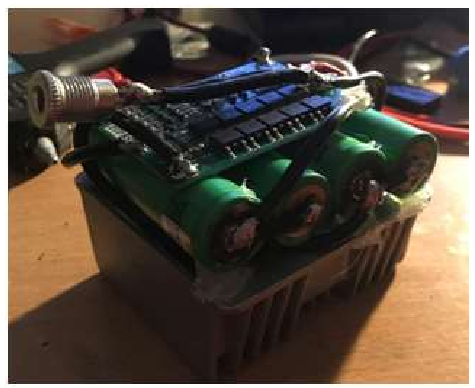
Twenty-one servos were assembled and used, one for each degree of freedom, with a peak current consumption of up to 1000 mA to ensure a high degree of similarity and the ability of the prototype to work as real human arm. Moreover, a battery was developed. The following requirements were drawn up for it: the ability to provide the prototype with power for a long period of time, being compact in mass and size in order to create a mobile and compact prosthesis that is close to a real human hand. The battery consists of four series-connected VTC 6 18650 lithium-ion batteries with a capacity of 3000 mAh and a peak current of 30 A (Figure 8). A balancing board was soldered to the batteries, the output was connected to a step-down DC-DC converter, which outputs 5.18 V, that was necessary and sufficient to power the servos of the prototype created.

4. Results and Discussion

Tests of individual components [12] and the operation of the control system [13] were carried out after the manufacture and assembly of a prototype of an anthropomorphic robotic arm. The developed experimental prototype of an anthropomorphic robotic arm with a large number of degrees of freedom provided a sufficient range of movements of the prosthesis, with the required degree of similarity with the movements of the human hand.
The mass-dimensional parameters of the created prototype of the anthropomorphic robotic arm were ergonomic and similar in properties to the human hand. The development had the smallest weight in comparison to the mass-dimension parameters of the currently used analogues (Table 2).
For an experimental characterization of the force of compression and gripping, weighing scales with a precision of 0.1 mg were placed on each fingertip with different durations of exposure. Holding a load weighing less than 1 kg was stable for 15 min for the fingers and more than 4 h for the arm mechanism. In the future, it will be possible to improve these parameters by using a material of the connecting elements of the phalanges with larger stiffness.
Simulations in CAD software and the prototype tests were carried out in which the anthropomorphic robotic arm emulated the different types of fingers and wrist movements, such as shown, for example, on Figure 3. The results obtained from the software and real simulation of different types of movements are summarized in Table 3.
Signals sufficient in magnitude to control the prototype of the anthropomorphic robotic arms were received, when connecting and sending a signal from a sensor glove and an electroencephalograph. It was experimentally established that the proposed control system is universal for connecting various types of control signal sources. The example of the measured transient response a test signal from a servo control for flexion/extension of a prosthetic finger is shown in Figure 9.
The next stage of the research was to increase the accuracy of reproducing the actions of the sensory glove, to refine the software for reproducing the movements of an anthropomorphic robotic arm in an augmented reality and to assemble and debug the brain–hand interface by means of an electroencephalograph.
The designed and assembled prototype of the robotic arm during testing showed a fairly good accuracy of repeating the movement of individual finger joints, combining the simplicity and reliability of the design in real time. The developed prototype differs from its analogues in a large number of degrees of freedom, which allows for more precise operations, ensuring the movement of each individual phalanx.
The novelty of the project lies in the design of an anthropomorphic robotic arm that simulates real human movements more accurately than existing analogues of bionic hands.

5. Conclusions

The robotic arm was developed in conjunction with a glove that will detect small movements in the user’s hand to control the prosthesis as a manipulator. Thus, the projected anthropomorphic robotic arm will be able to quickly and accurately simulate the movement of the user’s hand.
The designed and assembled prototype of the hand during testing showed a fairly good accuracy of reproducing the movement of individual finger joints, combining the simplicity and reliability of the design in real time. The developed prototype differs from its analogues in a large number of degrees of freedom, which allows for more precise manipulation operations, the movement of each individual phalanx is ensured.
The development can be used as a prosthesis for the purpose of the rehabilitation of people, or as a high-precision manipulator in cases where it is necessary to replace a person with a sufficiently accurate reproduction of actions by hand.

Author Contributions

Conceptualization, V.A.Y., G.V. and A.V.; methodology, V.A.Y., G.V. and A.V.; software, V.A.Y. and G.V.; validation, V.A.Y. and A.V.; investigation, V.A.Y. and G.V.; writing—original draft preparation, V.A.Y. and G.V.; writing—review and editing, V.A.Y. and A.V.; visualization, G.V. and A.V.; supervision, A.V.; project administration, A.V. All authors have read and agreed to the published version of the manuscript.

Funding

This research received no external funding.

Institutional Review Board Statement

Not applicable.

Informed Consent Statement

Not applicable.

Data Availability Statement

Not applicable.

Conflicts of Interest

The authors declare no conflict of interest.

References

  1. Lee, S.U.; Choi, Y.S.; Jeong, K.M.; Jung, S. Development of an underwater manipulator for maintaining nuclear power reactor. In Proceedings of the 2007 International Conference on Control, Automation and Systems, Seoul, Korea, 17–20 October 2007; pp. 1006–1010. [Google Scholar] [CrossRef]
  2. Marinceu, D.; Murchison, A.; Hatton, C. Use of robotic equipment in a Canadian Used Nuclear Fuel Packing Plant. In Proceedings of the 2012 2nd International Conference on Applied Robotics for the Power Industry (CARPI), Zurich, Switzerland, 11–13 September 2012; pp. 139–144. [Google Scholar] [CrossRef]
  3. Bae, H.Y.; Jae-Paeng, I.; Kim, S.; Park, S.Y.; Shin, H.S.; Kim, D.B.; Han, S.H. A Robust Control of Robotic Hand with Nine Axis for Assembly and Handling of Parts in Forging Manufacturing Process. In Proceedings of the 2018 International Conference on Information and Communication Technology Robotics (ICT-ROBOT), Busan, Korea, 6–8 September 2018; pp. 1–3. [Google Scholar] [CrossRef]
  4. Park, C.; Kyung, J.H.; Choi, T.Y.; Do, H.M.; Kim, B.I.; Lee, S.H. Design of an industrial dual arm robot manipulator for a Human-Robot hybrid manufacturing. In Proceedings of the 2012 9th International Conference on Ubiquitous Robots and Ambient Intelligence (URAI), Daejeon, Korea, 26–28 November 2012; pp. 616–618. [Google Scholar] [CrossRef]
  5. Zhang, J.; Wang, W.; Cai, Y.; Li, J.; Zeng, Y.; Chen, L.; Yuan, F.; Ji, Z.; Wang, Y.; Wyrwa, J. A Novel Single-Arm Stapling Robot for Oral and Maxillofacial Surgery—Design and Verification. IEEE Robot. Autom. Lett. 2022, 7, 1348–1355. [Google Scholar] [CrossRef]
  6. Tavakoli, M.; Enes, B.; Santos, J.; Marques, L.; de Almeida, A.T. Underactuated anthropomorphic hands: Actuation strategies for a better functionality. Robot. Auton. Syst. 2015, 74, 267–282. [Google Scholar] [CrossRef]
  7. Nurpeissova, A.; Tursynbekov, T.; Shintemirov, A. An Open-Source Mechanical Design of ALARIS Hand: A 6-DOF Anthropomorphic Robotic Hand. In Proceedings of the 2021 IEEE International Conference on Robotics and Automation (ICRA), Xi’an, China, 30 May–5 June 2021; pp. 1177–1183. [Google Scholar] [CrossRef]
  8. Sanchez-Velasco, L.E.; Arias-Montiel, M.; Enrique Guzmán-Ramírez, E.; Lugo-González, E. A Low-Cost EMG-Controlled Anthropomorphic Robotic Hand for Power and Precision Grasp. Biocybern. Biomed. Eng. 2020, 40, 221–237. [Google Scholar] [CrossRef]
  9. Light, C.M.; Chappell, P.H. Development of a lightweight and adaptable multiple-axis hand prosthesis. Med. Eng. Phys. 2000, 22, 679–684. [Google Scholar] [CrossRef]
  10. Plagenhoef, S.; Evans, F.G.; Abdelnour, T. Anatomical Data for Analyzing Human Motion. Res. Q. Exerc. Sport 1983, 54, 169–178. [Google Scholar] [CrossRef]
  11. ten Kate, J.; Smit, G.; Breedveld, P. 3D-printed upper limb prostheses: A review. Disabil. Rehabil. Assist. Technol. 2017, 12, 300–314. [Google Scholar] [CrossRef] [PubMed]
  12. He, Z.; Yurievich, R.R.; Shimizu, S.; Fukuda, M.; Kang, Y.; Shin, D. A Design of Anthropomorphic Hand based on Human Finger Anatomy. In Proceedings of the 2020 International Symposium on Community-centric Systems (CcS), Tokyo, Japan, 23–26 September 2020; pp. 1–5. [Google Scholar] [CrossRef]
  13. Atasoy, A.; Toptaş, E.; Kuchimov, S.; Gulfize, S.; Turpçu, M.; Kaplanoglu, E.; Güçlü, B.; Özkan, M. Biomechanical Design of an Anthropomorphic Prosthetic Hand. In Proceedings of the 2018 7th IEEE International Conference on Biomedical Robotics and Biomechatronics (Biorob), Enschede, The Netherlands, 26–29 August 2018; pp. 732–736. [Google Scholar] [CrossRef]
  14. Devaraja, R.R.; Maskeliūnas, R.; Damaševičius, R. Design and Evaluation of Anthropomorphic Robotic Hand for Object Grasping and Shape Recognition. Computers 2021, 10, 1. [Google Scholar] [CrossRef]
  15. Estay, D.; Basoalto, A.; Ardila-Rey, J.; Cerda, M.; Barraza, R. Development and Implementation of an Anthropomorphic Underactuated Prosthesis with Adaptive Grip. Machines 2021, 9, 209. [Google Scholar] [CrossRef]
  16. Fajardo, J.; Ferman, V.; Cardona, D.; Maldonado, G.; Lemus, A.; Rohmer, E. Galileo Hand: An Anthropomorphic and Affordable Upper-Limb Prosthesis. IEEE Access 2020, 8, 81365–81377. [Google Scholar] [CrossRef]
  17. Kashef, S.R.; Amini, S.; Akbarzadeh, A. Robotic hand: A review on linkage-driven finger mechanisms of prosthetic hands and evaluation of the performance criteria. Mech. Mach. Theory 2020, 145, 103677. [Google Scholar] [CrossRef]
  18. Laffranchi, M.; Boccardo, N.; Traverso, S.; Lombardi, L.; Canepa, M.; Lince, A.; Semprini, M.; Saglia, J.A.; Naceri, A.; Sacchetti, R.; et al. The Hannes hand prosthesis replicates the key biological properties of the human hand. Sci. Robot. 2020, 5, 46. [Google Scholar] [CrossRef] [PubMed]
  19. Leddy, M.T.; Dollar, A.M. Preliminary Design and Evaluation of a Single-Actuator Anthropomorphic Prosthetic Hand with Multiple Distinct Grasp Types. In Proceedings of the 2018 7th IEEE International Conference on Biomedical Robotics and Biomechatronics (Biorob), Enschede, The Netherlands, 26–29 August 2018; pp. 1062–1069. [Google Scholar] [CrossRef]
  20. Owen, M.; Au, C.; Fowke, A. Development of a Dexterous Prosthetic Hand. J. Comput. Inf. Sci. Eng. 2018, 18, 010801. [Google Scholar] [CrossRef]
  21. Baspinar, U.; Barol, H.S.; Senyurek, V.Y. Performance Comparison of Artificial Neural Network and Gaussian Mixture Model in Classifying Hand Motions by Using sEMG Signals. Biocybern. Biomed. Eng. 2013, 33, 33–45. [Google Scholar] [CrossRef]
  22. Barabulut, D.; Ortes, F.; Arslan, Y.Z.; Adli, M.A. Comparative evaluation of EMG signal features for myoelectric controlled human arm prosthetics. Biocybern. Biomed. Eng. 2017, 37, 326–335. [Google Scholar] [CrossRef]
  23. Hakonen, M.; Piitulainen, H.; Visala, A. Current state of digital signal processing in myoelectric interfaces and related applications. Biomed. Signal Processing Control 2015, 18, 334–359. [Google Scholar] [CrossRef]
  24. Mott, R.L.; Vavrek, E.M.; Wang, J. Machine Elements in Mechanical Design; Pearson: New York, NY, USA, 2018. [Google Scholar]
  25. Grebenstein, M.; Albu-Schäffer, A.; Bahls, T.; Chalon, M.; Eiberger, O.; Friedl, W.; Gruber, R.; Haddadin, S.; Hagn, U.; Haslinger, R.; et al. The DLR Hand Arm System. In Proceedings of the 2011 IEEE International Conference on Robotics and Automation (ICRA), Shanghai, China, 9–13 May 2011; pp. 3175–3182. [Google Scholar] [CrossRef]
  26. Grebenstein, M.; van der Smagt, P. Antagonism for a Highly Anthropomorphic Hand–Arm System. Adv. Robot. 2008, 22, 39–55. [Google Scholar] [CrossRef]
  27. Ben-Tzvi, P.; Zhou, M.A. Sensing and Force-Feedback Exoskeleton (SAFE) Robotic Glove. IEEE Trans. Neural Syst. Rehabil. Eng. 2015, 23, 992–1002. [Google Scholar] [CrossRef] [PubMed]
  28. Abougarair, A.J.; Shashoa, N.A.A.; Elmelhi, A.M.; Gnan, H.M. Real Time Classification for Robotic Arm Control Based Electromyographic Signal. In Proceedings of the 2022 IEEE 2nd International Maghreb Meeting of the Conference on Sciences and Techniques of Automatic Control and Computer Engineering (MI-STA), Sabratha, Libya, 23–25 May 2022; pp. 155–160. [Google Scholar] [CrossRef]
  29. Controzzi, M.; Clemente, F.; Barone, D.; Ghionzoli, A.; Cipriani, C. The SSSA-MyHand: A dexterous lightweight myoelectric hand prosthesis. IEEE Trans. Neural Syst. Rehabil. Eng. 2017, 25, 459–468. [Google Scholar] [CrossRef] [PubMed]
  30. Young, M.J.; Lin, D.J.; Hochberg, L.R. Brain-Computer Interfaces in Neurorecovery and Neurorehabilitation. Semin. Neurol. 2021, 41, 206–216. [Google Scholar] [CrossRef] [PubMed]
  31. Mullin, E.; This Man Set the Record for Wearing a Brain-Computer Interface. Wired 2022. Available online: https://www.wired.com/story/this-man-set-the-record-for-wearing-a-brain-computer-interface/ (accessed on 1 September 2022).
  32. Robohand. Hand and Forearm Prototype. YouTube. Available online: https://www.youtube.com/watch?v=PXw_nXA1t0c (accessed on 30 July 2022).
  33. Motion Capture Glove Frame. YouTube. Available online: https://www.youtube.com/watch?v=tT_MFeVPESs (accessed on 30 July 2022).
  34. Motorica Manifesto Hand. BionicsForEveryone.Com. Available online: https://bionicsforeveryone.com/motorica-manifesto-hand/#grip-patterns-control (accessed on 30 July 2022).
  35. 8E70—bebionic Hand EQD. Ottobock. Available online: https://www.ottobock.com/en-us/product/8E70 (accessed on 30 July 2022).
Figure 1. The flowchart of the main stages of the research.
Technologies 10 00103 g001
Figure 2. Designed and assembled finger construction made using three-dimensional printing technology; the process of manufacturing components of the mechanism.
Technologies 10 00103 g002
Figure 3. The main mechanical blocks of the projected robotic arm: (a) a mechanism for converting the rotational movement of the drive into linear; (b) a mechanism for finger extension and flexion; (c) a wrist mechanism.
Technologies 10 00103 g003
Figure 4. Simulation of the angular displacement on the example of the index finger.
Technologies 10 00103 g004
Figure 5. Engineered construction of an anthropomorphic robotic arm.
Technologies 10 00103 g005
Figure 6. Block diagram of the control system.
Technologies 10 00103 g006
Figure 7. Appearance of the designed board: (a) current measurements via servos; (b) control boards.
Technologies 10 00103 g007
Figure 8. Designed and assembled 16.7 V battery with a peak current of 30 A for autonomous power supply of the prototype.
Technologies 10 00103 g008
Figure 9. The sample of test impulse response of the servo of the index finger flexion (a) and extension (b).
Technologies 10 00103 g009
Table 1. The comparison of the main parameters of some modern designs of robotic arms.
ProjectDoFNumber of Actuators
Anthropomorphic robotic arm2217
Robotic arm [12]206
Robotic arm [13]205
Robotic arm [14]185
Robotic arm [15]153
Galileo Hand [16]156
Robotic arm [8]116
Hannes hand [18]91
MyoAdapt Hand [19]106
ALARIS hand [7]66
Robotic arm [20]107
Table 2. The comparison of the mass and size parameters of anthropomorphic robotic arms [32,33,34,35].
ProjectAnthropomorphic Robotic ArmBebionic 3 (England)Motorica Manifesto Hand (RF)
Mass, of the arm part kg0.5200.6980.482
maximum static weight, kg124520
battery options, mAh300022001200…3500
degree of freedom (DoF)2566
Table 3. The experimental results for the angular displacements and the required time of each finger and wrist of anthropomorphic robotic arm.
ParameterThe Required Time to Perform the Flexion/Extension, msFinger Angles of Full CompressionFinger Angles of Full ExtensionProximal PhalanxDistal Phalanx
Little finger0.189°90°90°83°
Ring finger0.189°90°90°82°
Middle finger0.189°90°90°82°
Index finger0.189°90°90°82°
Wrist rotation0.12----
Publisher’s Note: MDPI stays neutral with regard to jurisdictional claims in published maps and institutional affiliations.