
MINA: A Robotic Assistant for Hospital Fetching Tasks

 , ,
, ,  ,
,
Abstract
:1. Introduction
2. Related Work
2.1. Nursing Assistance and Service Robotics
2.2. Augmented Reality and Robot Navigation
2.3. Grasping Common Objects
2.4. SLAM and Use Of Barcodes
3. System Design
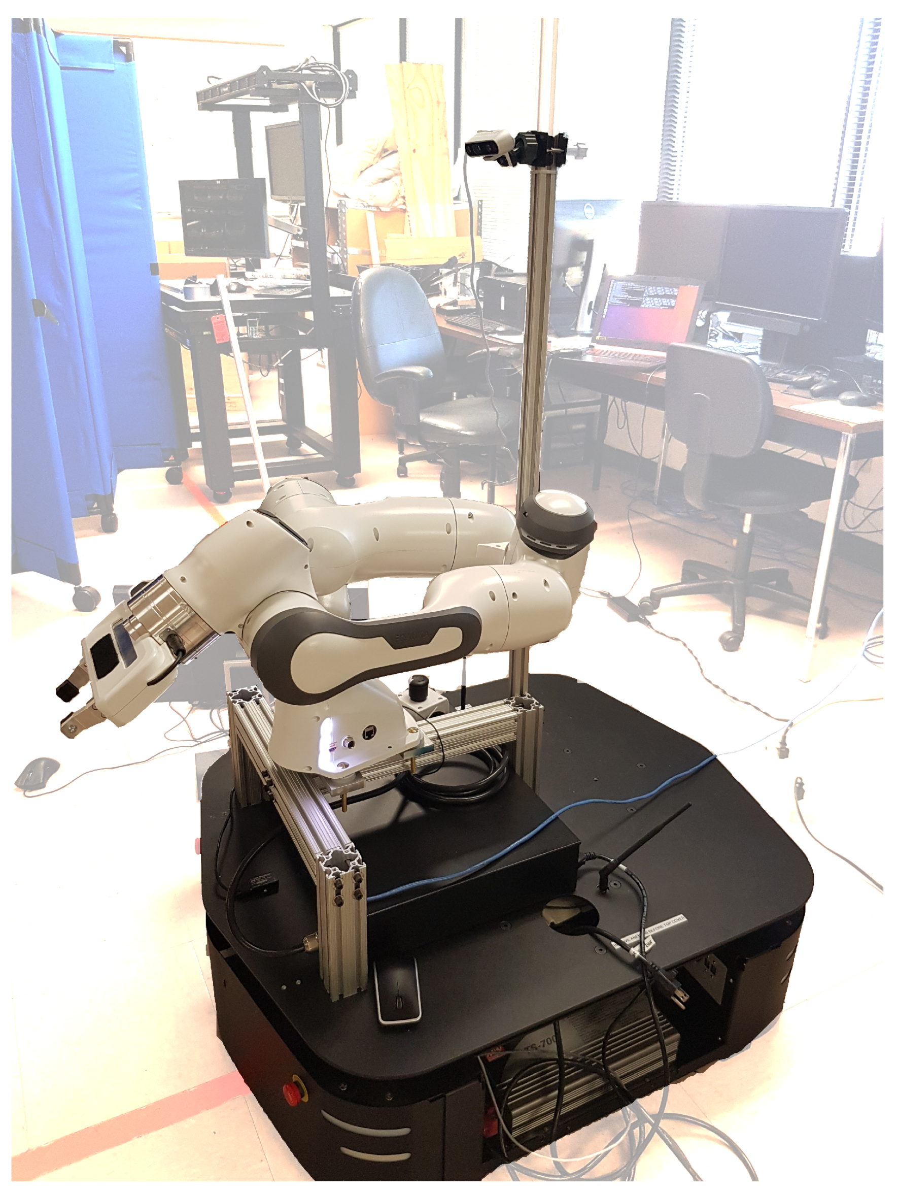
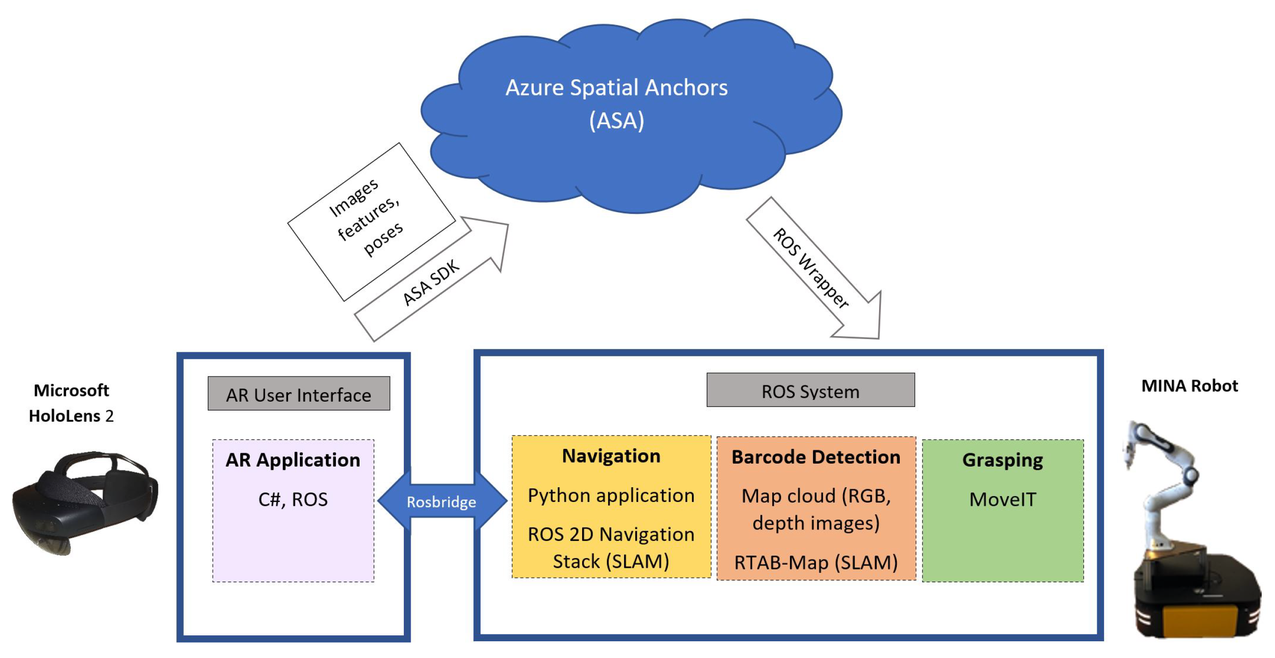
3.1. Hardware and Software Overview
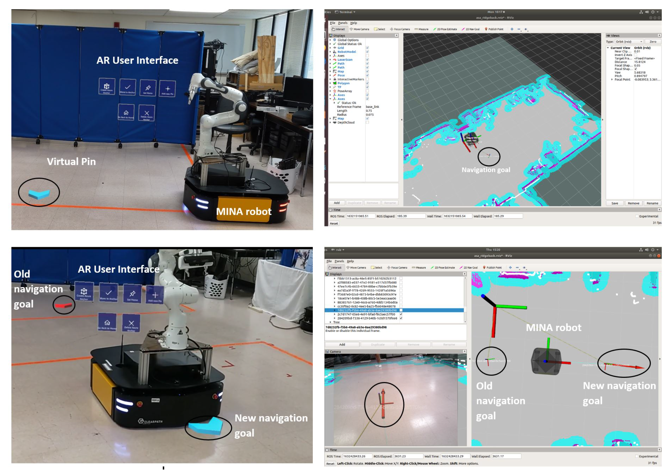
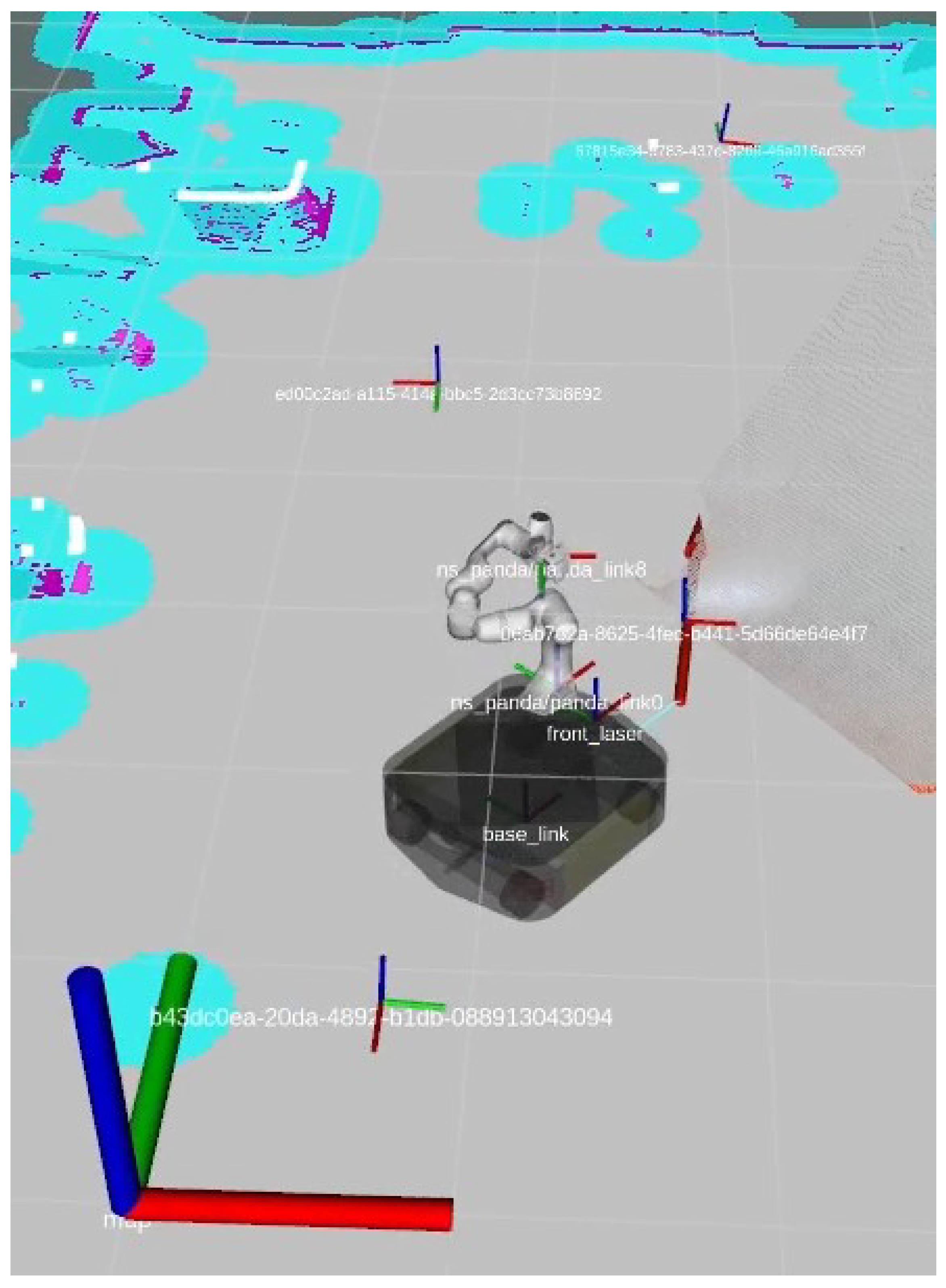
3.2. Augmented Reality User Interface and Navigation
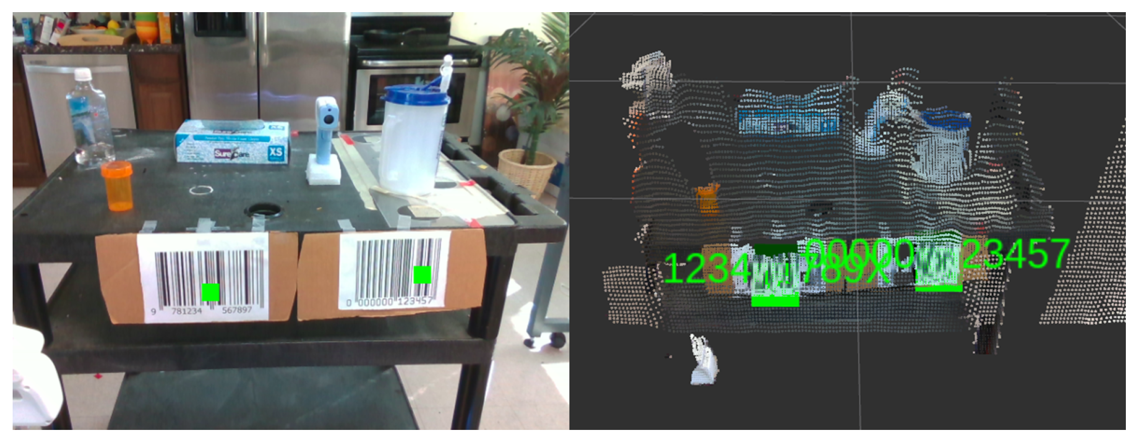
3.3. Barcode Detection and SLAM
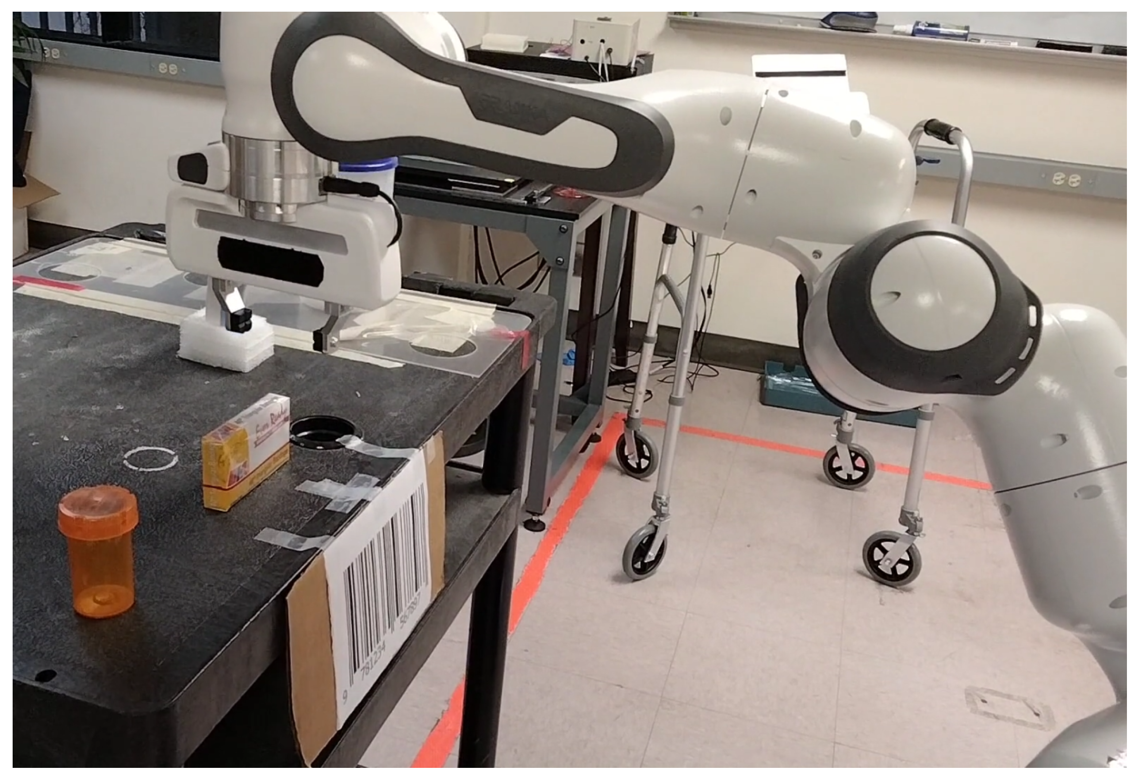
3.4. Grasping Control
4. Experiments
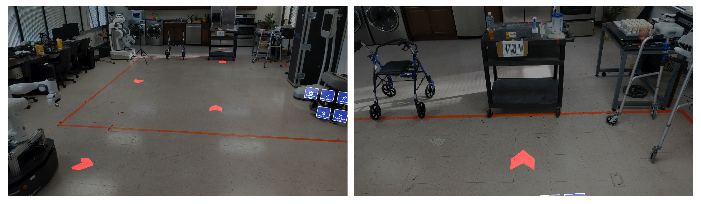
4.1. Experimental Setup
4.2. Experimental Results
5. Limitations and Future Work
6. Conclusions
Author Contributions
Funding
Institutional Review Board Statement
Informed Consent Statement
Data Availability Statement
Conflicts of Interest
References
- Occupational Employment and Wages. In U.S. Bureau of Labor Statistics; 2021. Available online: https://www.bls.gov/ooh/healthcare/registered-nurses.htm (accessed on 10 October 2021).
- Hall, L.H.; Johnson, J.; Watt, I.; Tsipa, A.; O’Connor, D.B. Healthcare staff wellbeing, burnout, and patient safety: A systematic review. PLoS ONE 2016, 11, e0159015. [Google Scholar] [CrossRef] [PubMed]
- Poghosyan, L.; Clarke, S.P.; Finlayson, M.; Aiken, L.H. Nurse burnout and quality of care: Cross-national investigation in six countries. Res. Nurs. Health 2010, 33, 288–298. [Google Scholar] [CrossRef] [PubMed] [Green Version]
- Caruso, C.C. Negative impacts of shiftwork and long work hours. Rehabil. Nurs. 2014, 39, 16–25. [Google Scholar] [CrossRef] [PubMed] [Green Version]
- Lucchini, A.; Iozzo, P.; Bambi, S. Nursing workload in the COVID-19 ERA. Intensive Crit. Care Nurs. 2020, 61, 102929. [Google Scholar] [CrossRef] [PubMed]
- Makary, M.A.; Daniel, M. Medical error—The third leading cause of death in the US. BMJ 2016, 353, i2139. [Google Scholar] [CrossRef]
- Kyrarini, M.; Lygerakis, F.; Rajavenkatanarayanan, A.; Sevastopoulos, C.; Nambiappan, H.R.; Chaitanya, K.K.; Babu, A.R.; Mathew, J.; Makedon, F. A Survey of Robots in Healthcare. Technologies 2021, 9, 8. [Google Scholar] [CrossRef]
- Nambiappan, H.R.; Kodur, K.C.; Kyrarini, M.; Makedon, F.; Gans, N. MINA: A Multitasking Intelligent Nurse Aid Robot. In Proceedings of the 14th PErvasive Technologies Related to Assistive Environments Conference, Corfu, Greece, 29 June–2 July 2021; pp. 266–267. [Google Scholar]
- Olson, E. AprilTag: A robust and flexible visual fiducial system. In Proceedings of the 2011 IEEE International Conference on Robotics and Automation, Shanghai, China, 9–13 May 2011; pp. 3400–3407. [Google Scholar]
- Garrido-Jurado, S.; Muñoz-Salinas, R.; Madrid-Cuevas, F.J.; Marín-Jiménez, M.J. Automatic generation and detection of highly reliable fiducial markers under occlusion. Pattern Recognit. 2014, 47, 2280–2292. [Google Scholar] [CrossRef]
- Munoz-Salinas, R.; Medina-Carnicer, R. UcoSLAM: Simultaneous localization and mapping by fusion of keypoints and squared planar markers. Pattern Recognit. 2020, 101, 107193. [Google Scholar] [CrossRef] [Green Version]
- George, L.; Mazel, A. Humanoid robot indoor navigation based on 2D bar codes: Application to the NAO robot. In Proceedings of the 2013 13th IEEE-RAS International Conference on Humanoid Robots (Humanoids), Atlanta, GA, USA, 15–17 October 2013; pp. 329–335. [Google Scholar]
- Kwon, W.; Park, J.H.; Lee, M.; Her, J.; Kim, S.H.; Seo, J.W. Robust autonomous navigation of unmanned aerial vehicles (UAVs) for warehouses’ inventory application. IEEE Robot. Autom. Lett. 2019, 5, 243–249. [Google Scholar] [CrossRef]
- Ackerman, E. How diligent’s robots are making a difference in Texas hospitals. IEEE Spectr. 2021. Available online: https://spectrum.ieee.org/how-diligents-robots-are-making-a-difference-in-texas-hospitals (accessed on 23 June 2021).
- ABB. ABB demonstrates concept of mobile laboratory robot for Hospital of the Future. ABB News. 2019. Available online: https://new.abb.com/news/detail/37279/hospital-of-the-future (accessed on 23 October 2021).
- Danesh, V.; Rolin, D.; Hudson, S.V.; White, S. Telehealth in mental health nursing education: Health care simulation with remote presence technology. J. Psychosoc. Nurs. Ment. Health Serv. 2019, 57, 23–28. [Google Scholar] [CrossRef] [PubMed]
- Robot APRN reports for Duty: School of Nursing receives funding for new, innovative technology. School of Nursing, The University of Texas at Austin. 2018. Available online: https://nursing.utexas.edu/news/robot-aprn-reports-duty-school-nursing-receives-funding-new-innovative-technology (accessed on 23 October 2021).
- Milgram, P.; Zhai, S.; Drascic, D.; Grodski, J. Applications of Augmented Reality for Human-Robot Communication. In Proceedings of the 1993 IEEE/RSJ International Conference on Intelligent Robots and Systems (IROS’93), Yokohama, Japan, 26–30 July 1993; Volume 3, pp. 1467–1472. [Google Scholar] [CrossRef]
- Beer, J.M.; Fisk, A.D.; Rogers, W.A. Toward a framework for levels of robot autonomy in human–robot interaction. J. Hum.-Robot Interact. 2014, 3, 74–99. [Google Scholar] [CrossRef] [PubMed] [Green Version]
- Roldan, J.J.; Pena-Tapia, E.; Garcia-Aunon, P.; Del Cerro, J.; Barrientos, A. Bringing Adaptive and Immersive Interfaces to Real-World Multi-Robot Scenarios: Application to Surveillance and Intervention in Infrastructures. IEEE Access 2019, 7, 86319–86335. [Google Scholar] [CrossRef]
- Baker, G.; Bridgwater, T.; Bremner, P.; Giuliani, M. Towards an immersive user interface for waypoint navigation of a mobile robot. arXiv 2020, arXiv:2003.12772. [Google Scholar]
- Kastner, L.; Lambrecht, J. Augmented-Reality-Based Visualization of Navigation Data of Mobile Robots on the Microsoft Hololens—Possibilities and Limitations. In Proceedings of the 2019 IEEE International Conference on Cybernetics and Intelligent Systems (CIS) and IEEE Conference on Robotics, Automation and Mechatronics (RAM), Bangkok, Thailand, 18–20 November 2019; pp. 344–349. [Google Scholar] [CrossRef]
- Chacko, S.M.; Granado, A.; RajKumar, A.; Kapila, V. An Augmented Reality Spatial Referencing System for Mobile Robots. In Proceedings of the 2020 IEEE/RSJ International Conference on Intelligent Robots and Systems (IROS), Las Vegas, NV, USA, 25–29 October 2020; pp. 4446–4452. [Google Scholar] [CrossRef]
- Ackerman, E. No human can match this high-speed box-unloading robot named after a pickle. IEEE Spectr. 2021. Available online: https://spectrum.ieee.org/no-human-can-match-this-highspeed-boxunloading-robot-named-after-a-pickle (accessed on 25 June 2021).
- Kragic, D.; Gustafson, J.; Karaoguz, H.; Jensfelt, P.; Krug, R. Interactive, Collaborative Robots: Challenges and Opportunities. In Proceedings of the International Joint Conference on Artificial Intelligence, Stockholm, Sweden, 13–19 July 2018; pp. 18–25. [Google Scholar]
- Ni, P.; Zhang, W.; Bai, W.; Lin, M.; Cao, Q. A new approach based on two-stream cnns for novel objects grasping in clutter. J. Intell. Robot. Syst. 2019, 94, 161–177. [Google Scholar] [CrossRef]
- Zapata-Impata, B.S.; Gil, P.; Pomares, J.; Torres, F. Fast geometry-based computation of grasping points on three-dimensional point clouds. Int. J. Adv. Robot. Syst. 2019, 16, 1729881419831846. [Google Scholar] [CrossRef] [Green Version]
- Xia, C.; Zhang, Y.; Shang, Y.; Liu, T. Reasonable grasping based on hierarchical decomposition models of unknown objects. In Proceedings of the 2018 15th International Conference on Control, Automation, Robotics and Vision (ICARCV), Singapore, 18–21 November 2018; pp. 1953–1958. [Google Scholar]
- Qiu, S.; Lodder, D.; Du, F. HGG-CNN: The Generation of the Optimal Robotic Grasp Pose Based on Vision. Intell. Autom. Soft Comput. 2020, 1517–1529. [Google Scholar] [CrossRef]
- Pumarola, A.; Vakhitov, A.; Agudo, A.; Sanfeliu, A.; Moreno-Noguer, F. PL-SLAM: Real-time monocular visual SLAM with points and lines. In Proceedings of the 2017 IEEE International Conference on Robotics and Automation (ICRA), Singapore, 29 May–3 June 2017; pp. 4503–4508. [Google Scholar]
- Mur-Artal, R.; Montiel, J.M.M.; Tardos, J.D. ORB-SLAM: A versatile and accurate monocular SLAM system. IEEE Trans. Robot. 2015, 31, 1147–1163. [Google Scholar] [CrossRef] [Green Version]
- Sumikura, S.; Shibuya, M.; Sakurada, K. Openvslam: A versatile visual slam framework. In Proceedings of the 27th ACM International Conference on Multimedia, Nice, France, 21–25 October 2019; pp. 2292–2295. [Google Scholar]
- Chakraborty, K.; Deegan, M.; Kulkarni, P.; Searle, C.; Zhong, Y. JORB-SLAM: A Jointly optimized Multi-Robot Visual SLAM. Available online: https://um-mobrob-t12-w19.github.io/docs/report.pdf (accessed on 12 October 2021).
- Quigley, M.; Conley, K.; Gerkey, B.; Faust, J.; Foote, T.; Leibs, J.; Wheeler, R.; Ng, A.Y. ROS: An open-source Robot Operating System. In ICRA Workshop on Open Source Software; ICRA Limited: Kobe, Japan, 2009; Volume 3, p. 5. [Google Scholar]
- Mace, J. ROSBridge. ROS.org. 2017. Available online: http://wiki.ros.org/rosbridge_suite (accessed on 13 July 2021).
- Holguin, D.E. Understanding anchoring with azure spatial anchors and azure object anchors. Microsoft. 2021. Available online: https://techcommunity.microsoft.com/t5/mixed-reality-blog/understanding-anchoring-with-azure-spatial-anchors-and-azure/ba-p/2642087 (accessed on 12 September 2021).
- Marder-Eppstein, E.; Berger, E.; Foote, T.; Gerkey, B.; Konolige, K. The office marathon: Robust navigation in an indoor office environment. In Proceedings of the 2010 IEEE International Conference on Robotics and Automation, Anchorage, AK, USA, 3–8 May 2010; pp. 300–307. [Google Scholar]
- Goerzen, C.; Kong, Z.; Mettler, B. A survey of motion planning algorithms from the perspective of autonomous UAV guidance. J. Intell. Robot. Syst. 2010, 57, 65–100. [Google Scholar] [CrossRef]
- Labbé, M.; Michaud, F. RTAB-Map as an open-source LiDAR and visual simultaneous localization and mapping library for large-scale and long-term online operation. J. Field Robot. 2019, 36, 416–446. [Google Scholar] [CrossRef]
- Zbar Bar Code Reader. SourceForge. 2011. Available online: http://zbar.sourceforge.net/ (accessed on 15 June 2021).
- Shen, J.; Gans, N. Robot-to-human feedback and automatic object grasping using an RGB-D camera–projector system. Robotica 2018, 36, 241–260. [Google Scholar] [CrossRef]
- Rajpathak, K.; Kodur, K.C.; Kyrarini, M.; Makedon, F. End-User Framework for Robot Control. In Proceedings of the 14th PErvasive Technologies Related to Assistive Environments Conference, Corfu, Greece, 29 June–2 July 2021; pp. 109–110. [Google Scholar]
- Nowacki, P.; Woda, M. Capabilities of ARCore and ARKit platforms for ar/vr applications. In International Conference on Dependability and Complex Systems; Springer: Brunow, Poland, 2019; pp. 358–370. [Google Scholar]


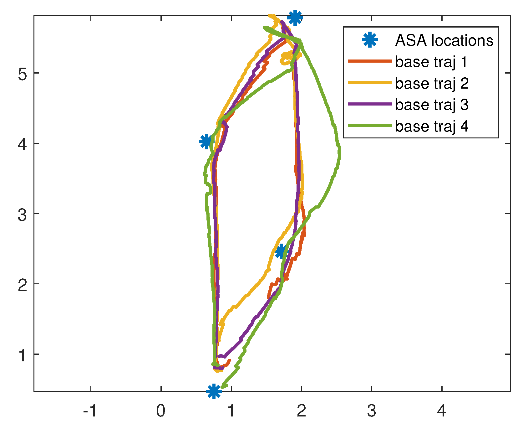
| Time between ASAs (secs) | ||||
|---|---|---|---|---|
| trial | 1-2 | 2-3 | 3-4 | 4-1 |
| 1 | 4.620 | 26.260 | 9.7390 | 29.1580 |
| 2 | 8.8030 | 17.4880 | 30.6030 | 21.00 |
| 3 | 11.0520 | 21.8800 | 25.5200 | 20.6170 |
| 4 | 15.1890 | 20.7850 | 25.5120 | 20.7140 |
| mean | 8.1657 | 20.8760 | 21.9540 | 23.5917 |
| Time between ASAs (secs) | ||||
|---|---|---|---|---|
| trial | 1-2 | 2-3 | 3-4 | 4-1 |
| 1 | 11.2360 | 48.8050 | 73.6020 | 67.0440 |
| 2 | 14.0240 | 47.9820 | 38.9340 | 63.4510 |
| 3 | 15.8380 | 28.2120 | 69.5370 | 21.0270 |
| mean | 13.5370 | 38.5085 | 71.5695 | 44.0355 |
Publisher’s Note: MDPI stays neutral with regard to jurisdictional claims in published maps and institutional affiliations. |
© 2022 by the authors. Licensee MDPI, Basel, Switzerland. This article is an open access article distributed under the terms and conditions of the Creative Commons Attribution (CC BY) license (https://creativecommons.org/licenses/by/4.0/).
Share and Cite
Nambiappan, H.R.; Arboleda, S.A.; Lundberg, C.L.; Kyrarini, M.; Makedon, F.; Gans, N. MINA: A Robotic Assistant for Hospital Fetching Tasks. Technologies 2022, 10, 41. https://doi.org/10.3390/technologies10020041
Nambiappan HR, Arboleda SA, Lundberg CL, Kyrarini M, Makedon F, Gans N. MINA: A Robotic Assistant for Hospital Fetching Tasks. Technologies. 2022; 10(2):41. https://doi.org/10.3390/technologies10020041
Chicago/Turabian StyleNambiappan, Harish Ram, Stephanie Arevalo Arboleda, Cody Lee Lundberg, Maria Kyrarini, Fillia Makedon, and Nicholas Gans. 2022. "MINA: A Robotic Assistant for Hospital Fetching Tasks" Technologies 10, no. 2: 41. https://doi.org/10.3390/technologies10020041
APA StyleNambiappan, H. R., Arboleda, S. A., Lundberg, C. L., Kyrarini, M., Makedon, F., & Gans, N. (2022). MINA: A Robotic Assistant for Hospital Fetching Tasks. Technologies, 10(2), 41. https://doi.org/10.3390/technologies10020041