Abstract
In this paper, a robotic Multitasking Intelligent Nurse Aid (MINA) is proposed to assist nurses with everyday object fetching tasks. MINA consists of a manipulator arm on an omni-directional mobile base. Before the operation, an augmented reality interface was used to place waypoints. Waypoints can indicate the location of a patient, supply shelf, and other locations of interest. When commanded to retrieve an object, MINA uses simultaneous localization and mapping to map its environment and navigate to the supply shelf waypoint. At the shelf, MINA builds a 3D point cloud representation of the shelf and searches for barcodes to identify and localize the object it was sent to retrieve. Upon grasping the object, it returns to the user. Collision avoidance is incorporated during the mobile navigation and grasping tasks. We performed experiments to evaluate MINA’s efficacy including with obstacles along the path. The experimental results showed that MINA can repeatedly navigate to the specified waypoints and successfully perform the grasping and retrieval task.
1. Introduction
Nurses represent the largest portion of health professionals and play vital roles in healthcare. Nurses provide and coordinate patient care and educate patients and the public about health conditions. The U.S. Bureau of Labor Statistics projects that the needed number of nurses will grow by 9% over the next decade []. Growth will occur for a number of reasons, including primary and preventive care for a growing population, increasing rates of chronic conditions, and healthcare services demand for an aging population.
Safe, high-quality healthcare depends on the physical and mental well-being of nurses and other healthcare personnel []. Nurse burnout is a widespread phenomenon described by a decrease in nurses’ energy, emotional exhaustion, lack of motivation, and feelings of frustration, all of which can lead to a decrease in work efficacy and productivity. A study of fifty-three-thousand eight-hundred forty-six nurses from six countries showed a strong correlation between nurse burnout and ratings of care quality []. Nurses are often overburdened, stressed, work long hours, and suffer from a lack of sleep and a poor diet []. During the COVID-19 pandemic, the nurse workload increased, and nurses were under stress and pressure due to the need to provide intensive care to COVID-19 patients and longer working hours [].
Nurses are responsible for a dizzying number of tasks: assessing patients’ conditions, observing patients and recording data (including vital signs), recording patients’ medical histories and symptoms, administering patients’ treatments, operating and monitoring medical equipment, transferring or walking patients (especially after surgery), performing diagnostic tests and analyzing the results, ensuring a clean and sterilized environment for the patient, establishing plans for patients’ care or contributing information to existing plans, consulting and collaborating with doctors and other healthcare professionals, educating patients and their families on how to manage illnesses or injuries, devising at-home treatment and monitoring after discharge from hospital, training new nurses and students, and other tasks. Typically, nurses are directly responsible for 6–8 patients during their 10–12 h shift. Hospitals and other healthcare facilities are obligated to ensure the safety of patients and minimize medical errors, which is the third leading cause of death in the U.S. []. Enhancing the work of nurses is vital to ensure quality healthcare and directly contributes to the nation’s economic and social well-being. Pervasive technologies offer the potential to improve the work performances of tomorrow’s nurses in multiple ways, including improving the productivity, efficacy, occupational safety, and quality of nurses’ work life [].
We envision the future of work for nurses to be enhanced by a Multitasking Intelligent Nurse Aid (MINA) robotic system. One of MINA’s primary tasks would be to retrieve items from supply rooms, sparing the nurse time and effort. However, healthcare facilities usually are complex, dynamic environments. Such fetching tasks could benefit from human–robot interaction, where nurses or other users can provide location information to the robot to assist it in task planning and navigation. For instance, a user can set or update navigation waypoints for a robot system to follow and fetch items needed for direct patient care. This would require a natural, intuitive interface to specify waypoints and visualize their location.
In this work, the focus is on using the MINA robotic system in a medical supply scenario, where the robot will be used for fetching and providing medical items. The scenario can be divided into the following steps; (1) navigation towards the supply cart when the robot receives a request, (2) locating an object of interest by visually detecting and reading barcodes, (3) grasping the required item from the supply cart, and (4) returning the fetched items to the required destination.
For Steps (1) and (4), our navigation concept involves human–robot interaction using Augmented Reality (AR), as it allows hospital staff to set specific waypoints in an indoor area using virtual navigation pins and natural interfaces. The waypoints can be related to the location’s interest, e.g., supply shelves, doorways, bedside, etc. To enable users’ free movement in a given space and hands-free interaction, we used an Augmented Reality Head-Mounted Display (ARHMD). Once waypoints have been established, the user commands the robot to move to a specific waypoint to fetch a specific object and bring it back. For Step (2), RGB and depth images are used to build a 3D point cloud map of the location. The images are then processed to detect barcodes in the scene and determine their 3D location with respect to the robot. In Step (3), the barcode position is collected from the point cloud map and sent to the robot arm. A collision-free trajectory is calculated to position the gripper around the object. With the object grasped by the gripper, the arm is moved to a pose suitable for transportation. A previous paper presented the preliminary work of this project []. This paper presented the initial design of the assistive robot and was limited to the validation of Step (2).
The main contributions of this paper are as follows: (1) Barcode detection has been used mostly as a means of localizing mobile robots in navigation and SLAM, as seen in works such as [,,,,]. Most of these works have used manually placed markers rather than the barcodes that are already in the environment on products. Additionally, we used barcode detection and localization, in a novel manner, to perform the task of grasping the object by identifying the barcode and mapping its location in a point cloud for fetching the object. (2) We used augmented reality in the context of human–robot collaboration to allow the user to place waypoints for robotic navigation in real time. For that, we implemented a novel approach of using AR with a cloud-based service, Azure Spatial Anchors, as a means for mobile robotic navigation.
The paper proceeds as follows. A review of previous and related research is presented in Section 2. In Section 3, we present the design of the MINA robot, including its user interface, hardware, and software systems. Experimental tests of the MINA robot in carrying out a fetching task are presented in Section 4. We discuss the current limitations of MINA and the directions these present for future efforts in Section 5 before concluding in Section 6.
2. Related Work
2.1. Nursing Assistance and Service Robotics
There is notable research focusing on robotics to provide assistance to nurses, such as supplying items and acting as a teammate while nurses focus on treating patients, especially during pandemics []. Robots such as Moxi and YuMi were developed for such purposes. Moxi primarily focuses on autonomous supply and delivery of items to patient rooms [], and YuMi, a mobile robot developed by ABB, primarily functions to assist medical staff in handling laboratory-based items in hospitals [].
Both of the robots were tested in hospitals in Texas, and YuMi was primarily tested in Texas Medical Center in Houston, Texas.
There are also robots that are designed to assist nurses by training and preparing them for the use of new technologies. Danesh et al. [] focused on the robot RoboAPRN, which uses remote presence telehealth technology designed to provide remote communication and assessments to prepare nursing students in using telecommunication, through a simulation lab especially on psychiatric/mental health care delivery [].
2.2. Augmented Reality and Robot Navigation
AR has the potential to facilitate the communication between humans and robots []. For mobile service robots, AR can improve navigation by enabling human operators to set waypoints. Waypoint navigation provides humans with a supervisory role as they are in charge of task planning, leaving only the local path-planning to the robot []. Furthermore, waypoint navigation has the potential to reduce the workload of users [] as it allows users to delegate some tasks to robots creating a human–robot collaborative environment and turning the robot into an assistant.
Waypoint navigation is one use of the ARHMDs for mobile robots in human–robot collaboration, as augmented and virtual reality can provide an immersive interface for robot control. Baker et al. [] presented a target selection interface in virtual reality using a head-mounted display to allow waypoint navigation of mobile robots. Kästner and Lambrecht [] presented a prototype of the AR visualization of the navigation of mobile robots using the Microsoft HoloLens. Further, Chacko et al. [] presented a spatial referencing system using AR that allows users to tag and allocate tasks for a robotic system to be performed at those locations.
2.3. Grasping Common Objects
With their maneuverability, precision, and speed and a variety of end-effector options (grippers, hands, vacuums, etc.), robot manipulators have long been used for pick and place tasks ranging from automotive assembly lines moving heavy chassis to small delicate silicon chip components. While their use is widely limited to industrial and manufacturing scenarios, more recent efforts have focused on the pick and place of unstructured items in cluttered environments such as box packing or use in-home and workplace service robots [,]. Ni et al. [] implemented a two-stream convolutional neural network to extract features from RGB image and depth image data and performed two-fingered parallel-jawed grasping on objects in a cluttered environment. Zapata-Impata et al. [] developed a geometry-based approach to perform grasping by finding the best pair of grasping points on an object surface using point cloud data. Xia et al. [] focused on grasping by implementing a cuckoo search strategy on point cloud data to obtain a hierarchical decomposition model and used a region decision method to evaluate the grasping position on the object. There are also research works such as [] that focus on the estimation of the optimal grasping pose of the robot arm to fetch objects through a hybrid generative grasping convolutional neural network.
2.4. SLAM and Use Of Barcodes
Simultaneous Localization and Mapping (SLAM) has been an active research topic for years in the field of robotics. In particular, vision-based SLAM (Visual SLAM (VSLAM)) utilizes visual information such as camera images and depth sensing. PL-SLAM [] is a VSLAM approach that is based on ORB-SLAM [], with improved efficiency by modifying the original approach to include simultaneous point and line processing, enabling VSLAM to work in low-textured and motion-blurred scenes. OpenVSLAM [] is a graph-based SLAM approach that uses three modules: tracking, mapping, and global optimization.
There are some notable works that incorporate barcodes with SLAM and other navigation methods for robotic navigation. Some research works use square fiducial markers, which are akin to 2D barcodes (e.g., April tags [] and ArUco tags []). UcoSLAM [] uses keypoints in the environment along with square fiducial markers as part of its SLAM method, where a map can be created only through markers, keypoints, or through a bot. JORB-SLAM [] is another SLAM method that uses ORB-SLAM in a collaborative multi-agent scenario for quicker and greater area coverage, where AprilTags are used for robot-to-robot loop closure. George et al. [] used AprilTags as 2D barcodes to construct a map of the environment for the localization and navigation of a humanoid robot in indoor environments. Kwon et al. [] used unmanned aerial vehicles with barcode readers for autonomous navigation in a warehouse scenario, and the barcode data were used among other data such as odometry, altitude, velocity, etc. to create map and path for the UAV navigation.
3. System Design
The system architecture is presented in Figure 1. The first part of the MINA robotic system involves robot navigation to a point of interest. To facilitate that, the user sets a location by placing a virtual pin. The second part of the system involves the process of identifying objects and locations by detecting barcodes and building a point cloud map. The third part of the system involves the fetching task, where the robot moves to the identified location of the objects and performs the grasping operation to fetch the objects.
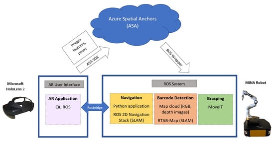
Figure 1.
Overview of MINA’s system architecture.
3.1. Hardware and Software Overview
The MINA robot consists of a Franka Emika Panda robot manipulator mounted on a Clearpath Ridgeback mobile base. The Panda has seven joints, with torque sensors at each joint allowing for compliant control. The Panda payload is 3 kg, with a reach of 855 mm. The Ridgeback base is omnidirectional through the use of Mecanum wheels. It is 960 mm long, 730 mm wide, and 311 mm high, with a payload of 100 kg. It has a pair of integrated LiDARs with a field of view in the front and rear parts of the base. The Ridgeback carries and provides power to the Panda arm, as well as its controller. We added an Intel Realsense D435i RGBD camera to perform object identification localization, as well as build 3D maps of the environment. The MINA robot can be seen in Figure 2.
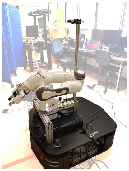
Figure 2.
The MINA robot (highlighted) consists of a Franka Emika Panda robot manipulator mounted on a Clearpath Ridgeback mobile base. Sensors include LiDARs and an RGBD camera.
Both the Panda arm and Ridgeback mobile base have drivers for the Robot Operating System (ROS). We leveraged the ROS for integration and control [], in order to leverage its large community and open-source packages. One such package is Moveit, which is used to calculate forward and inverse kinematics, collision-free joint trajectories, and visualization data. The ROS runs on an internal computer in the Ridgeback mobile base. Due to the computational load of perception, mapping, navigation, and object detection, two laptops running additional ROS threads were carried as the payload by the Ridgeback. The consolidation of the computation is an avenue of future work.
Merging the Ridgeback base and Panda arm within Moveit is not trivial. The Ridgeback base and Panda arm are designed to function as independent robots, and simply networking their respected computer systems causes multiple software conflicts and errors. The most critical of these errors are related to naming collisions in joints, links, executables, and data pipelines. The solution required moving all of the Panda software into a unique namespace during runtime. This prepends all joint, link, executable, and data pipeline names to avoid conflict. A new static joint was created in the software to define the connection between the base and arm. With these changes, MINA can function as a single unified robot with Moveit.
3.2. Augmented Reality User Interface and Navigation
The MINA navigation control interface employed the Microsoft Hololens 2 ARHMD and was developed using Unity 2020.3.12f1 and the Mixed Reality Toolkit 2.7.2.0. for the HoloLens. To exchange information between the robotic system and the Microsoft HoloLens, we used ROSBridge [] libraries, as they provide a JSON API that allows ROS publishing and subscribing functionalities to any other application.
In order to share the navigation goals between the Microsoft HoloLens and the robotic system, we use an Azure Mixed Reality Service named Azure Spatial Anchors (ASA). An ASA is a representation of a real physical point that persists in the cloud and can be queried later by any other device that connects to the service []. ASAs allow users to specify locations in non-static environments, which is the case of hospital hallways. Further, ASAs support different devices and platforms, such as the Microsoft HoloLens and mobile devices (through ARKit and ARCore), allowing seamless information exchange. There are other solutions that could have been considered for navigation, such as using markers (e.g., AprilTags or Vuforia Image Markers), but we preferred to avoid the additional step of modifying the environment.
Our application sends information about the ASA by publishing a message to a topic in the ROS. This message is processed by a back-end application in Python, which collects the location and orientation of the spatial anchor and sets the ASA as an ROS navigation goal (see Figure 3, top and bottom left) including the desired orientation for the robot using the navigation goal (as opposed to simply specifying the location). This facilitates searching for barcodes and grasping the desired objects, i.e., the camera mounted on the robot must be facing the potential objects, and the arm must be oriented within reaching distance. After the navigation goal has been received, the MINA robot makes a 360° turn to scan the room, looking for ASAs. To enable the ASA, the robot is equipped with an ASUS Xtion RGBD camera. Additionally, we used RViz as a 3D visualizer for ROS to check the location of the ASA in the map; see Figure 3 (top and bottom right). Once the robot has found and localized one or more ASAs in the map, a new anchor can be created to be sent to the MINA robot as a new navigational goal (see Figure 3, bottom right and left).
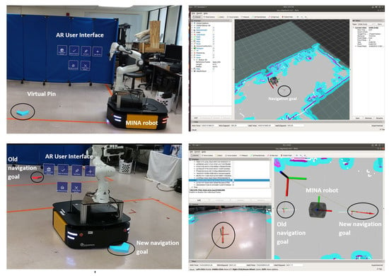
Figure 3.
User interface: (Top left) The AR interface with 6 buttons to set navigation goals. A virtual pin is located in front of the robot. (Top right) The RViz rendering of the map and the navigation goal. (Bottom left) The MINA robot moving to a new navigation goal; the previous navigation goal is shown in red. (Bottom right) The RViz rendering of the map and navigation goals.
The MINA robot uses the ROS 2D Navigation Stack. This software stack utilizes the robot’s wheel odometry, IMU navigation, and LiDAR to perform SLAM and collision-free navigation. Using OpenSlam’s Gmapping, the Navigation Stack uses the LiDAR data to localize the robot with Adaptive Monte Carlo Localization (AMCL) and fuses this result with the vehicle odometry via an extended Kalman filter. The LiDAR data are used to create a three-dimensional collision map in the form of a voxel grid, and this is then flattened into a two-dimensional cost map. The navigation stack uses an ROS topic to input a navigation goal coordinate from higher-level software, such as our AR user interface []. Both a global path planner and a local path planner are used to navigate the robot from its current location to the goal coordinates.
The ROS has multiple global and local path planner algorithms, including the Dynamic Window Approach (DWA), trajectory rollout, A*, and Dijkstra’s algorithm []. The MINA robot is configured to use the DWA for its local path planner and Dijkstra’s algorithm for its global path planner. Trajectory roll out offers a more detailed forward simulation of acceleration than the DWA at the expense of greater computational expense. However, this detail is not necessary for a robot with a powerful drive train as the Clearpath Ridgeback. A*, if configured correctly, can offer a computationally less expensive global path planner than Dijkstra. However, in a complex environment such as a hospital or medical suite, the optimal solution provided by Dijkstra’s algorithm provides more reliable and safer navigation. The Ridgeback base is a large robot with a capable Intel processor for the computationally more expensive Dijkstra’s algorithm.
The ROS Navigation Stack can be started with or without a pre-existing map. In our experiments, we constructed a map with the LiDAR data and saved it to the robot’s files system. This map was reloaded alongside Azure Spatial Anchors.
3.3. Barcode Detection and SLAM
There were three steps that were performed in terms of barcode detection and SLAM to enable the robot grasping task. The first step in this process was creating a point cloud map of the environment in front of the robot. In our current case, this was an experimental supply cart filled with barcodes and objects. During the process of point cloud map creation, the system simultaneously performs barcode detection and identifies the locations of the barcodes and the corresponding objects placed with them. Once the barcode locations are identified, the system places a marker point for each barcode location in the point cloud map, which is used by the robot to perform the fetching task on the object.
The barcode detection and map cloud creation are performed using RGB and depth images obtained from an RGBD 3D camera. As shown in Figure 2, the camera is mounted on the robot from which it performs barcode detection and map cloud creation by obtaining RGB and depth images. The point cloud map is created from the RGB and depth images using a SLAM approach called Real-Time Appearance-Based Mapping (RTAB-Map) [], which is a graph-based SLAM approach with a loop closure detector that uses a bag-of-words approach to determine the location of an image for loop closure detection.
The barcode detection process is shown in Figure 4. We used the European Article Number (EAN-13) barcodes placed right below the objects, as shown in Figure 5. The motivation for using the EAN-13 barcodes was their popularity in consumer products and supply shelves. The barcode detection and localization were implemented using OpenCV and the ZBar library []. OpenCV is used to convert the RGB images to grayscale, which are then passed to the zbar library. The zbar library performs the barcode detection and location identification process using three main components: image scanner, linear scanner, and decoder. The image scanner scans the two-dimensional images to produce a linear intensity sample stream The linear scanner scans the intensity sample stream to produce a bar width stream using one-dimensional signal processing techniques. The decoder scans and decodes the bar width stream to produce the barcode data and other information such as the barcode type and its 2D location in the image.
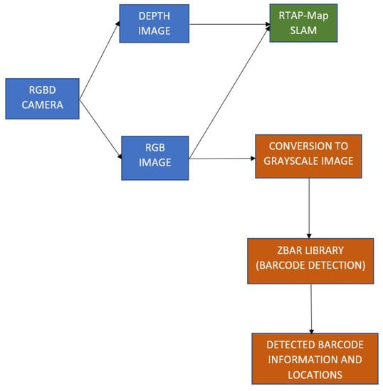
Figure 4.
Barcode detection and SLAM architecture.
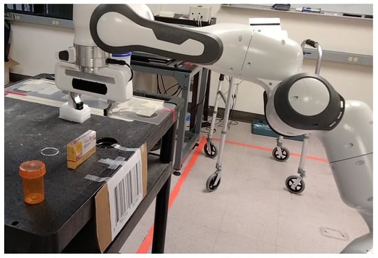
Figure 5.
Barcodes placed below the items in front of the MINA robot.
Once the barcode location is identified in the image, the depth value of the barcode at that location is obtained from the depth image. The depth values from the depth image are passed to a spatial median filter to remove noise, and the appropriate depth value at the barcode location is obtained. Given the barcode location and depth value, the location of the barcode in the point cloud map is obtained by mapping the values with respect to the RGBD camera’s transform frame.
Let be the pixel coordinates of the detected barcode in the image and d the depth value at in the depth image. Let be the location of the barcode in the point cloud map with respect to the point cloud map’s reference frame. Let be the focal lengths of the camera and be the principal points of the camera. The 2D image coordinates are converted to 3D world coordinates as:
Scaling by 1000 converts the camera depth units in millimeters to the point cloud map units in meters. For placing the marker points, text- and cube-based markers are used, through which the barcode information and its location can be identified, as shown in Figure 6. The camera is mounted on the robot at a height of 40 cm above the robot mobile base, and the camera is able to detect the barcode at a distance of approximately 93 cm from the cart.
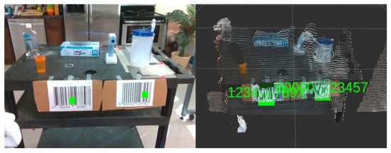
Figure 6.
Two barcodes detected in the RGB image and indicated by green squares.
3.4. Grasping Control
To implement grasping control, an existing robot control framework MoveIt was used. Our software uses MoveIt in order to calculate a coordinate waypoint navigation plan to precisely move to and pick up the object. MoveIt includes a virtual planning environment, in which the occupied space can be mapped for collision avoidance. The MoveIt motion planning algorithms then ensure that no part of the robot enters into this space. The coordinates of the objects were obtained from the barcode detection module and were then transformed into the robot arm’s frame of reference. The control interface was implemented using both a GUI built using the PyQt5 platform and an ROS topic interface. Grasping can be initiated and controlled with either the GUI or ROS topic.
MoveIt enables collision-free movement and control of our robotic arm, including forward and inverse kinematics, during run-time. While the base is moving, the arm is in a tucked position to reduce vibration and induced moments. Before initiating a grasping task, the arm untucks. During this stage, the cart, objects, camera, and camera pole are mapped as occupied space. This ensures that there are no collisions with the environment or camera system. When the arm is untucked and ready for grasping, the occupied space designation surrounding the object is removed, so the gripper can approach the object. An end effector waypoint is calculated 15 cm above the object and another at the object’s location, so the gripper fingers are on both sides of it. The robotic arm untucks, moves through these waypoints, grasps the object by closing the gripper, moves reverse through these waypoints, and tucks, ready for the robot base to move. While the object is held by the gripper, the collision avoidance space is extended to include the grasped object and avoid collisions with the table or camera system.
4. Experiments
A series of experiments was conducted to test the capability of the MINA system in a fetching task. The MINA system is still in a preliminary design phase, but the results indicated its efficacy and potential for future capability.
4.1. Experimental Setup
The experiments were intended to replicate a medical supply shelf or cart scenario. A typical medical supply cart is shown in Figure 7. A laboratory cart was placed with multiple objects placed on it, and barcodes were attached below each. MINA then performed navigation, barcode detection, and the grasping task.
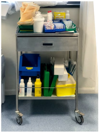
Figure 7.
Typical medical supply cart used in hospitals.
Using the Microsoft HoloLens and ASAs, we placed four anchor points, including the home position, to define the path for the robot to navigate, see Figure 8 (left). The home position was set as the first anchor point, and two anchor points were placed along the robot path from the home position to a supply cart holding various objects; another anchor point was placed on the return path from the cart to the home position. Since the main focus was on a hospital scenario, medical-related objects were used for the fetching tasks in the experiments, including a prescription pill bottle, a box of bandages, a thermometer, and a water jug. The objects were placed on the laboratory cart with barcodes attached to it. An EAN-13-type barcode was attached to the cart below the object of interest for target detection and localization. Due to the camera resolution, the barcode was oversized in this proof-of-concept work. Future efforts will focus on using the barcodes that are on object packaging or smaller ones printed and placed on the shelves. This can be seen in Figure 8 (Right).

Figure 8.
(Left) A view of the three ASAs that the robot will visit. A fourth ASA was added to the left of the cart to make the return safer. (Right) A view of the cart with graspable objects, the barcode, and the ASA near the cart.
The map generated by the robot, including reference frames associated with each ASA that were used for navigation, can be seen in Figure 9. The experiments were repeated multiple times. We present data for four trials without any obstacles and three trials with an obstacle placed in the robot motion path. The obstacle was placed in the path of the robot between Anchor Point 1 and Anchor Point 2.
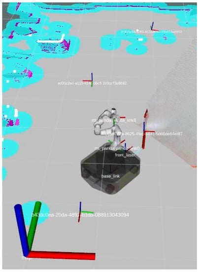
Figure 9.
Anchor points placed along the path of the robot.
4.2. Experimental Results
Figure 10 shows the plot of the robot movement in comparison to the specified anchor point locations for the four trials. The robot maneuvered within 30 cm of each ASA waypoint before it moved to the next. Note that the starting and ending positions are at the bottom of the figure, and the shelf is at the top. The robot motion is counterclockwise when viewed on a top-down map. The robot paused at the object shelf while the arm moved to grasp the object. The trajectories were notably consistent across the tests. In Trial 4, the robot sensed one of the human observers and moved around to the right of where he had been. In Table 1, we present the travel times between each ASA waypoint for each trial, as well as the mean travel times. The times in each trial were consistent. The travel time from ASA 1 to 2 did not require much rotation of the robot, so its time was notably shorter. The rotation speed is a tunable parameter, so the time can be reduced between ASAs in the future.
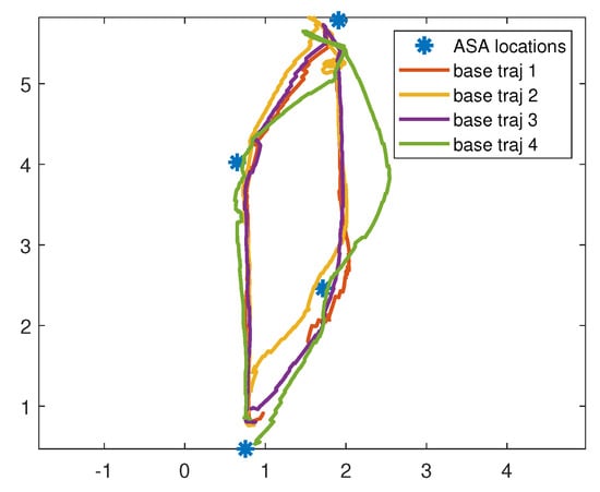
Figure 10.
Plot of robot base trajectories for four trials with respect to the ASA locations. The base moves within a neighborhood of each ASA. At ASA 2, which is the cart, it performs the barcode identification and object grasping task.

Table 1.
The travel times between ASA waypoints for each trial with no obstacles.
Images of the robot base movement from one of the fetching task experiments, starting from the home position towards the cart, grasping the object, and then, returning back to the home position, are shown in Figure 11. Figure 12 shows the barcode that is detected and highlighted as a separate frame in the point cloud shown from both the camera view and rviz view respectively.
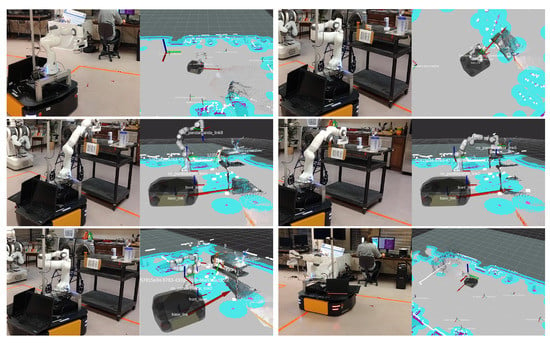
Figure 11.
(Top left) Robot moving from home position to Anchor 1 waypoint. (Top right) Robot moving from Anchor 1 waypoint to Anchor 2 waypoint. (Middle left) Robot getting into pre-grasp position. (Middle right) Robot grasping the object. (Bottom left) Robot getting into post-grasp position. (Bottom right) Robot moving to home position.
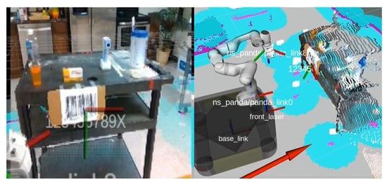
Figure 12.
Barcode detected and highlighted at the detected location in the point cloud shown from camera view (left) and rviz view (right).
Experiments with an obstacle in the path were performed to see the consistency of robot motion with respect to the ASA waypoint locations while performing collision avoidance. An obstacle was placed between ASA 1 and ASA 2. Figure 13 shows plots of three robot motion trajectories with respect to ASA locations while performing collision avoidance. It can be seen that the robot moved further right once it detected the obstacle, thus preventing a collision and still reaching the ASA 2 waypoint near the experimental cart. In Trial 1, between ASA 3 and home, the robot detected the obstacle and moved alongside it for a short distance to make sure it was added to the map. Table 2 shows the time for travel between each waypoint for each trial. There was notably more variation in times compared to the trials when there was no obstacle, as the robot slowed down for safety when near the obstacle, even if it did not need to alter its course.
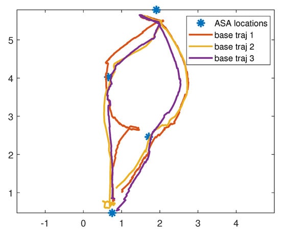
Figure 13.
Plots of the robot base trajectories over three trials with respect to the ASA locations for the case of an obstacle between ASAs 1 and 2. The robot moves to the right of the obstacle to avoid it.

Table 2.
The travel times between ASA waypoints for each trial with an obstacle between Waypoints 1 and 2.
Figure 14 provides a series of images collected during an experiment with an obstacle between ASA 1 and ASA 2 (Trial 2 in Figure 13). From Figure 14, it can be seen that the robot was able to successfully perform collision avoidance, following which it was able to identify and move towards the specified anchor point location. This capability of not deviating from the path, even in the presence of obstacles, will make the robot more efficient in hospital navigation scenarios, especially in supply shelf or fetching scenarios, where there are high chances of obstacles being present in its navigation path.
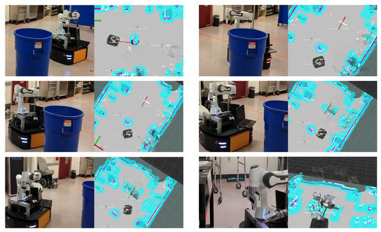
Figure 14.
Robot motion while avoiding the obstacle in the path to the experimental cart: (top left) robot detecting the obstacle; (top right, middle left, middle right, bottom left) robot moving around the obstacle; (bottom right) robot moving to Anchor 2 waypoint after avoiding the obstacle.
5. Limitations and Future Work
This work, while in the preliminary stage, presents opportunities for assisting nurses through robotic systems. However, we acknowledge that MINA currently has limited applicability in realistic hospital settings. This provides the direction for our future efforts. One limitation is the current barcode detection system, which relies on the camera having an unobstructed view of a rather large barcode. This is not the case in typical hospital stockrooms, where the barcodes on objects or on shelves are small. We will investigate mounting a camera on the end effector of the robotic arm to scan barcodes on a shelf or on items and incorporate them into the 3D map. We feel using existing barcodes is preferable to adding markers such as QR-style codes such as the April or ArUco tags.
Another limitation is that object grasping is currently open-loop. Closed-loop grasp planning based on 3D images is an area of future effort. Currently, the vision-based functionality used for the grasping task is based on barcode detection and mapping its location to the 3D point in the point cloud. We will investigate the use of 2D and 3D image data to localize the objects, such as in our prior works [] (which used clustering in the 3D point cloud) and [] (which used deep learning to identify classes of objects). Using barcodes to identify objects will still reduce the need for extensive training to identify specific items.
Additionally, our AR user interface is presented through the Microsoft HoloLens. However, there are other devices that could be used to set waypoints, e.g., mobile phones or more than one ARHMD. All these devices could be used simultaneously to connect to the ASA cloud service and exchange information. This can provide multiple users, nurses in our scenario, the possibility to add stops to the robot trajectory before delivering an item. An initial investigation of ASA using ARCore for Android devices [] is seen in Figure 15, in which ASAs were placed in the same location as for the experiments in Section 4. Mobile devices have more limited interfaces than gesture recognition in Hololens, creating new challenges in the placement and orientation of ASAs.
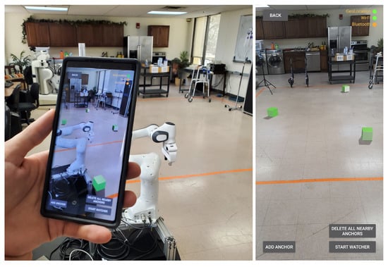
Figure 15.
The ASAs used for robot navigation recreated on an Android device using ARCore. (Left) A view of the mobile app rendering points. (Right) A screen capture showing the default user interface.
6. Conclusions
MINA is designed as a multitasking robotic aid for nursing assistance, which consists of a manipulator arm and an RGBD camera mounted on a mobile base. Navigational waypoints are specified through an AR-based control interface using Azure Spatial Anchors, which are later used by the robotic system for navigation. Barcode detection and 3D point cloud representation, built using RGBD camera images, are incorporated for object localization, which is then used for the robotic grasping task, while the grasping control is implemented using the MoveIt framework. Experiments were conducted with the robot while performing a fetching task on an experimental cart filled with medical items. Tests included cases with obstacles between the waypoints. The results showed that the robot was able to consistently navigate to the specified spatial anchor waypoints and perform the grasping task, with and without an obstacle in the path.
Author Contributions
Conceptualization, M.K., F.M. and N.G.; methodology, H.R.N., S.A.A. and N.G.; formal analysis, H.R.N., C.L.L. and N.G.; investigation, H.R.N., S.A.A. and N.G.; experiment, H.R.N., C.L.L. and N.G.; writing—original draft preparation, H.R.N., C.L.L., S.A.A. and N.G.; writing— review and editing, H.R.N., S.A.A., C.L.L., M.K., F.M. and N.G.; supervision, N.G.; project administration, F.M. and N.G.; funding acquisition, F.M. and N.G. All authors have read and agreed to the published version of the manuscript.
Funding
This material is based on work supported by the National Science Foundation under Grant No. NSF PFI: BIC 1719031 and by The University of Texas at Arlington Research Institute in collaboration with the German Academic Exchange Service (DAAD).
Institutional Review Board Statement
No human studies were conducted in this research, and institutional review was not necessary.
Informed Consent Statement
No human studies were conducted in this research, and informed consent was not necessary.
Data Availability Statement
Data in this study will be made available upon request to the corresponding authors.
Conflicts of Interest
The authors declare no conflict of interest. The funders had no role in the design of the study; in the collection, analyses, or interpretation of the data; in the writing of the manuscript; nor in the decision to publish the results.
References
- Occupational Employment and Wages. In U.S. Bureau of Labor Statistics; 2021. Available online: https://www.bls.gov/ooh/healthcare/registered-nurses.htm (accessed on 10 October 2021).
- Hall, L.H.; Johnson, J.; Watt, I.; Tsipa, A.; O’Connor, D.B. Healthcare staff wellbeing, burnout, and patient safety: A systematic review. PLoS ONE 2016, 11, e0159015. [Google Scholar] [CrossRef] [PubMed]
- Poghosyan, L.; Clarke, S.P.; Finlayson, M.; Aiken, L.H. Nurse burnout and quality of care: Cross-national investigation in six countries. Res. Nurs. Health 2010, 33, 288–298. [Google Scholar] [CrossRef] [PubMed] [Green Version]
- Caruso, C.C. Negative impacts of shiftwork and long work hours. Rehabil. Nurs. 2014, 39, 16–25. [Google Scholar] [CrossRef] [PubMed] [Green Version]
- Lucchini, A.; Iozzo, P.; Bambi, S. Nursing workload in the COVID-19 ERA. Intensive Crit. Care Nurs. 2020, 61, 102929. [Google Scholar] [CrossRef] [PubMed]
- Makary, M.A.; Daniel, M. Medical error—The third leading cause of death in the US. BMJ 2016, 353, i2139. [Google Scholar] [CrossRef]
- Kyrarini, M.; Lygerakis, F.; Rajavenkatanarayanan, A.; Sevastopoulos, C.; Nambiappan, H.R.; Chaitanya, K.K.; Babu, A.R.; Mathew, J.; Makedon, F. A Survey of Robots in Healthcare. Technologies 2021, 9, 8. [Google Scholar] [CrossRef]
- Nambiappan, H.R.; Kodur, K.C.; Kyrarini, M.; Makedon, F.; Gans, N. MINA: A Multitasking Intelligent Nurse Aid Robot. In Proceedings of the 14th PErvasive Technologies Related to Assistive Environments Conference, Corfu, Greece, 29 June–2 July 2021; pp. 266–267. [Google Scholar]
- Olson, E. AprilTag: A robust and flexible visual fiducial system. In Proceedings of the 2011 IEEE International Conference on Robotics and Automation, Shanghai, China, 9–13 May 2011; pp. 3400–3407. [Google Scholar]
- Garrido-Jurado, S.; Muñoz-Salinas, R.; Madrid-Cuevas, F.J.; Marín-Jiménez, M.J. Automatic generation and detection of highly reliable fiducial markers under occlusion. Pattern Recognit. 2014, 47, 2280–2292. [Google Scholar] [CrossRef]
- Munoz-Salinas, R.; Medina-Carnicer, R. UcoSLAM: Simultaneous localization and mapping by fusion of keypoints and squared planar markers. Pattern Recognit. 2020, 101, 107193. [Google Scholar] [CrossRef] [Green Version]
- George, L.; Mazel, A. Humanoid robot indoor navigation based on 2D bar codes: Application to the NAO robot. In Proceedings of the 2013 13th IEEE-RAS International Conference on Humanoid Robots (Humanoids), Atlanta, GA, USA, 15–17 October 2013; pp. 329–335. [Google Scholar]
- Kwon, W.; Park, J.H.; Lee, M.; Her, J.; Kim, S.H.; Seo, J.W. Robust autonomous navigation of unmanned aerial vehicles (UAVs) for warehouses’ inventory application. IEEE Robot. Autom. Lett. 2019, 5, 243–249. [Google Scholar] [CrossRef]
- Ackerman, E. How diligent’s robots are making a difference in Texas hospitals. IEEE Spectr. 2021. Available online: https://spectrum.ieee.org/how-diligents-robots-are-making-a-difference-in-texas-hospitals (accessed on 23 June 2021).
- ABB. ABB demonstrates concept of mobile laboratory robot for Hospital of the Future. ABB News. 2019. Available online: https://new.abb.com/news/detail/37279/hospital-of-the-future (accessed on 23 October 2021).
- Danesh, V.; Rolin, D.; Hudson, S.V.; White, S. Telehealth in mental health nursing education: Health care simulation with remote presence technology. J. Psychosoc. Nurs. Ment. Health Serv. 2019, 57, 23–28. [Google Scholar] [CrossRef] [PubMed]
- Robot APRN reports for Duty: School of Nursing receives funding for new, innovative technology. School of Nursing, The University of Texas at Austin. 2018. Available online: https://nursing.utexas.edu/news/robot-aprn-reports-duty-school-nursing-receives-funding-new-innovative-technology (accessed on 23 October 2021).
- Milgram, P.; Zhai, S.; Drascic, D.; Grodski, J. Applications of Augmented Reality for Human-Robot Communication. In Proceedings of the 1993 IEEE/RSJ International Conference on Intelligent Robots and Systems (IROS’93), Yokohama, Japan, 26–30 July 1993; Volume 3, pp. 1467–1472. [Google Scholar] [CrossRef]
- Beer, J.M.; Fisk, A.D.; Rogers, W.A. Toward a framework for levels of robot autonomy in human–robot interaction. J. Hum.-Robot Interact. 2014, 3, 74–99. [Google Scholar] [CrossRef] [PubMed] [Green Version]
- Roldan, J.J.; Pena-Tapia, E.; Garcia-Aunon, P.; Del Cerro, J.; Barrientos, A. Bringing Adaptive and Immersive Interfaces to Real-World Multi-Robot Scenarios: Application to Surveillance and Intervention in Infrastructures. IEEE Access 2019, 7, 86319–86335. [Google Scholar] [CrossRef]
- Baker, G.; Bridgwater, T.; Bremner, P.; Giuliani, M. Towards an immersive user interface for waypoint navigation of a mobile robot. arXiv 2020, arXiv:2003.12772. [Google Scholar]
- Kastner, L.; Lambrecht, J. Augmented-Reality-Based Visualization of Navigation Data of Mobile Robots on the Microsoft Hololens—Possibilities and Limitations. In Proceedings of the 2019 IEEE International Conference on Cybernetics and Intelligent Systems (CIS) and IEEE Conference on Robotics, Automation and Mechatronics (RAM), Bangkok, Thailand, 18–20 November 2019; pp. 344–349. [Google Scholar] [CrossRef]
- Chacko, S.M.; Granado, A.; RajKumar, A.; Kapila, V. An Augmented Reality Spatial Referencing System for Mobile Robots. In Proceedings of the 2020 IEEE/RSJ International Conference on Intelligent Robots and Systems (IROS), Las Vegas, NV, USA, 25–29 October 2020; pp. 4446–4452. [Google Scholar] [CrossRef]
- Ackerman, E. No human can match this high-speed box-unloading robot named after a pickle. IEEE Spectr. 2021. Available online: https://spectrum.ieee.org/no-human-can-match-this-highspeed-boxunloading-robot-named-after-a-pickle (accessed on 25 June 2021).
- Kragic, D.; Gustafson, J.; Karaoguz, H.; Jensfelt, P.; Krug, R. Interactive, Collaborative Robots: Challenges and Opportunities. In Proceedings of the International Joint Conference on Artificial Intelligence, Stockholm, Sweden, 13–19 July 2018; pp. 18–25. [Google Scholar]
- Ni, P.; Zhang, W.; Bai, W.; Lin, M.; Cao, Q. A new approach based on two-stream cnns for novel objects grasping in clutter. J. Intell. Robot. Syst. 2019, 94, 161–177. [Google Scholar] [CrossRef]
- Zapata-Impata, B.S.; Gil, P.; Pomares, J.; Torres, F. Fast geometry-based computation of grasping points on three-dimensional point clouds. Int. J. Adv. Robot. Syst. 2019, 16, 1729881419831846. [Google Scholar] [CrossRef] [Green Version]
- Xia, C.; Zhang, Y.; Shang, Y.; Liu, T. Reasonable grasping based on hierarchical decomposition models of unknown objects. In Proceedings of the 2018 15th International Conference on Control, Automation, Robotics and Vision (ICARCV), Singapore, 18–21 November 2018; pp. 1953–1958. [Google Scholar]
- Qiu, S.; Lodder, D.; Du, F. HGG-CNN: The Generation of the Optimal Robotic Grasp Pose Based on Vision. Intell. Autom. Soft Comput. 2020, 1517–1529. [Google Scholar] [CrossRef]
- Pumarola, A.; Vakhitov, A.; Agudo, A.; Sanfeliu, A.; Moreno-Noguer, F. PL-SLAM: Real-time monocular visual SLAM with points and lines. In Proceedings of the 2017 IEEE International Conference on Robotics and Automation (ICRA), Singapore, 29 May–3 June 2017; pp. 4503–4508. [Google Scholar]
- Mur-Artal, R.; Montiel, J.M.M.; Tardos, J.D. ORB-SLAM: A versatile and accurate monocular SLAM system. IEEE Trans. Robot. 2015, 31, 1147–1163. [Google Scholar] [CrossRef] [Green Version]
- Sumikura, S.; Shibuya, M.; Sakurada, K. Openvslam: A versatile visual slam framework. In Proceedings of the 27th ACM International Conference on Multimedia, Nice, France, 21–25 October 2019; pp. 2292–2295. [Google Scholar]
- Chakraborty, K.; Deegan, M.; Kulkarni, P.; Searle, C.; Zhong, Y. JORB-SLAM: A Jointly optimized Multi-Robot Visual SLAM. Available online: https://um-mobrob-t12-w19.github.io/docs/report.pdf (accessed on 12 October 2021).
- Quigley, M.; Conley, K.; Gerkey, B.; Faust, J.; Foote, T.; Leibs, J.; Wheeler, R.; Ng, A.Y. ROS: An open-source Robot Operating System. In ICRA Workshop on Open Source Software; ICRA Limited: Kobe, Japan, 2009; Volume 3, p. 5. [Google Scholar]
- Mace, J. ROSBridge. ROS.org. 2017. Available online: http://wiki.ros.org/rosbridge_suite (accessed on 13 July 2021).
- Holguin, D.E. Understanding anchoring with azure spatial anchors and azure object anchors. Microsoft. 2021. Available online: https://techcommunity.microsoft.com/t5/mixed-reality-blog/understanding-anchoring-with-azure-spatial-anchors-and-azure/ba-p/2642087 (accessed on 12 September 2021).
- Marder-Eppstein, E.; Berger, E.; Foote, T.; Gerkey, B.; Konolige, K. The office marathon: Robust navigation in an indoor office environment. In Proceedings of the 2010 IEEE International Conference on Robotics and Automation, Anchorage, AK, USA, 3–8 May 2010; pp. 300–307. [Google Scholar]
- Goerzen, C.; Kong, Z.; Mettler, B. A survey of motion planning algorithms from the perspective of autonomous UAV guidance. J. Intell. Robot. Syst. 2010, 57, 65–100. [Google Scholar] [CrossRef]
- Labbé, M.; Michaud, F. RTAB-Map as an open-source LiDAR and visual simultaneous localization and mapping library for large-scale and long-term online operation. J. Field Robot. 2019, 36, 416–446. [Google Scholar] [CrossRef]
- Zbar Bar Code Reader. SourceForge. 2011. Available online: http://zbar.sourceforge.net/ (accessed on 15 June 2021).
- Shen, J.; Gans, N. Robot-to-human feedback and automatic object grasping using an RGB-D camera–projector system. Robotica 2018, 36, 241–260. [Google Scholar] [CrossRef]
- Rajpathak, K.; Kodur, K.C.; Kyrarini, M.; Makedon, F. End-User Framework for Robot Control. In Proceedings of the 14th PErvasive Technologies Related to Assistive Environments Conference, Corfu, Greece, 29 June–2 July 2021; pp. 109–110. [Google Scholar]
- Nowacki, P.; Woda, M. Capabilities of ARCore and ARKit platforms for ar/vr applications. In International Conference on Dependability and Complex Systems; Springer: Brunow, Poland, 2019; pp. 358–370. [Google Scholar]
Publisher’s Note: MDPI stays neutral with regard to jurisdictional claims in published maps and institutional affiliations. |
© 2022 by the authors. Licensee MDPI, Basel, Switzerland. This article is an open access article distributed under the terms and conditions of the Creative Commons Attribution (CC BY) license (https://creativecommons.org/licenses/by/4.0/).