Article

Theoretical and Experimental Investigation of Geomagnetic Energy Effect for LEO Debris Deorbiting

1
Institute of Mechanics, Chinese Academy of Sciences, Beijing 100190, China
2
School of Engineering Sciences, University of Chinese Academy of Sciences, Beijing 100049, China
*
Author to whom correspondence should be addressed.
These authors contributed equally to this work.
Aerospace 2022, 9(9), 511; https://doi.org/10.3390/aerospace9090511
Submission received: 29 June 2022 / Revised: 7 September 2022 / Accepted: 11 September 2022 / Published: 14 September 2022
(This article belongs to the Special Issue Space Debris Removal: Challenges and Opportunities)

Abstract

:
Space debris is increasingly problematic and needs active removal, especially in low Earth orbits (LEO). Paying for the vast cost of the disposal of debris from the situation is still inevitable even though pivotal technical hurdles have been overcome with the growing maturity of capturing and deorbiting methods. To this end, a novel geomagnetic energy (GME) propellant approach is firstly proposed to propel a spinning tethered spacecraft for LEO debris deorbiting, without the use of expendable fuel and a large-length tether. In this method, the time-cumulative effect of the interacted torque of the spacecraft’s electromagnet and geomagnetic field is used to accelerate the rotating system for GME storage, and the space momentum exchange from the angular momentum of system to the linear momentum of debris is introduced to deorbit the debris for GME release. Next, an on-orbit directional GME storage mechanism is built, and the corresponding two optimal strategies are put forward. Both theoretical and simulation results demonstrate that GME can be stored in the expected direction on any inclined LEO below 1000 km. Deorbiting kg-level debris can be accomplished within several orbital periods with the existing magnetorquer technology. Finally, proof-of-principle experiments of the GME effect are performed and elementarily validate the LEO GME utilization in space.

1. Introduction

The space debris (SD) problem is becoming dangerous [1]. Earth’s debris field now includes more than 27,000 cataloged objects larger than 10 cm in diameter, and over 70% are distributed between 500 km and 1000 km of the low Earth orbit (LEO) [2,3]. Moreover, an exponential increase in SD will arise from collision cascades among large objects in the next 200 years, and they pose serious safety threats to operational satellites due to potential impacts or collisions [4,5]. Therefore, annually removing at least five large SD is suggested and a significantly urgent task to stabilize the SD environment in LEO [6].
An active removal mission for the large SD usually includes two main steps: a capturing step for the servicer spacecraft to rendezvous with a targeted SD and capture it, and a deorbiting step for the captured SD to lower its orbital altitude constantly by propulsion technologies (i.e., an amount delta-V, symbolized as Δ V ) and finally remove it to reentry into the Earth’s atmosphere [7,8]. For the capturing step, many contact capturing techniques have been proposed in the past decade [9,10], several of which have been applied or demonstrated in on-orbit flight experiments, such as robotic arms [11], nets and harpoons [12,13]. However, for the deorbiting step, reducing the orbit of the captured SD object to reentry consumes large amounts of fuel by using conventional chemical or electric propulsion [14]. Even worse, only a piece of SD can be cleaned up in one mission. Consequently, so far, none of the items of SD has been removed from orbit due to the excessively high costs [15,16].
To improve the cost effectiveness of a removal mission, many propulsion approaches without the use of propulsive fuel are raised gradually based on the space environmental force (including electrodynamic tethers [17], solar sails [18] and drag sails [19]), and space momentum exchange (i.e., momentum exchange tethers [20]), etc. Nevertheless, after capturing, the on-orbit deployment of the tether with an enormous length of tens of kilometers and a sail with a massive area of over ten thousand square meters is still a technical challenge that is difficult to achieve with the latest technology, limiting their on-orbit implementation [21,22,23]. Additionally, the deorbiting times of these methods are up to several hours, even a year or more, and the number of SD objects removed in a single mission is extremely limited [24]. The large-scale coupling with long-term deorbiting indicates that the tether- or sail–satellite collision probabilities are significantly (hundreds of times) greater than those of satellite–satellite collision [25].
Herein, we focus on a new propellantless approach to SD deorbiting in LEO. For one thing, we find a way to produce Δ V . A spinning momentum exchange tether propulsion can convert the spin angular momentum of the SD-spacecraft system to the linear momentum of SD [26]. The huge space scale and high fuel consumption for the required Δ V have seriously limited the further development of this momentum exchange form in recent years. Nevertheless, it is still a potential way to reduce the orbital altitude of SD [27]. That is, by a rotating tether system, the captured SD on one end of the tether can experience a continuous acceleration to gain Δ V as long as an enduring angular momentum injection source is provided [28]. Then, momentum exchange occurs when the SD is released at the required Δ V , and the transfer of momentum to the released SD will deorbit it to reenter.
For another, the search for the angular momentum source mentioned above is required. On-orbit experiments of electrodynamic tethers and studies on magnetic propulsion have demonstrated that the external natural magnetic field around the Earth can be a significant “propellant” resource for satellites in LEO [16,29]. Immersed in the Earth’s magnetic field, the “propellant” can be used to produce a net torque on an electromagnet (i.e., current-carrying loop) carried by the deorbiter spacecraft, and the torque tends to turn the loop into alignment with the magnetic field [3,30]. Obviously, a sustained torque is exerted on the rotating tethered spacecraft-debris system when given active electromagnets, and spin up the rotating system continually. Therefore, the time-cumulative effect of the magnetic torque, namely the geomagnetic energy (GME) effect, can become the angular momentum source. What is more, the acceleration process requires no expendable fuel, and the tether length is dramatically reduced, compared with that of momentum exchange tethers and electrodynamic tethers.
In this paper, a novel approach to LEO debris deorbiting is proposed based on the GME effect of an electromagnet and the space momentum exchange of spin angular momentum to linear momentum. Based on the active control strategy of the electromagnets we proposed, the external torque acts incessantly on the spinning tethered spacecraft-SD system to harvest the angular momentum. The absorbed angular momentum of the system is then transferred to the Δ V required for deorbiting when the SD is released in the right direction. Additionally, the proposed approach relies on the energy derived from sunlight instead of expendable onboard fuel. Over time, it can build up considerable stored angular momentum and has no saturation for removing the SD with different Δ V required. In particular, the biggest advantage is that the present approach does not require on-orbit operation after capturing a SD, and can deorbit a 10 kg SD within days through a tether with a length of 10 m to 100 m. The space length of the above tether-based methods often reaches several to tens of kilometers to deorbit a LEO SD within months to years. The drag-augmentation-based technologies require on-orbit operation after capturing a SD, and the deorbiting process can last for up to years, greatly increasing the collision probability. That is to say, it is the first propellantless deorbiting approach that does not have the disadvantages of the previous methods. Herein, to clarify the feasibility and on-orbit realizability of the proposed approach, we establish the mechanism of GME storage and treat the storage and deorbiting capability for SD in LEO. Simulations for mechanism verification are carried out. Then, the system modeling and control are investigated to develop a ground experimental system. Finally, we complete the proof-of-principle experiment for an elementary verification of GME utilization in LEO.
The main contributions of this paper relative to others are as follows:
  • A novel GME propellant approach to LEO debris rapid deorbiting is first proposed based on the time-cumulative effect of torque produced by a magnetic moment of spacecraft interacting with the Earth’s magnetic field. It can significantly reduce removal costs. Additionally, the method is characterized by low dependence on spatial scale and effective control mechanism and strategies.
  • A mechanism of on-orbit directional GME storage is built for the deorbiting spacecraft. Two energy storage strategies are further developed, and they can be flexibly selected according to the orbit of space debris for obtaining Δ V .
  • The GME harvesting, exchange, and storage are experimentally achieved with a novel self-developed ground system, and the LEO GME utilization in space is elementarily verified. It demonstrates that the proposed GME propellant approach has remarkable engineering realizability.

2. Geomagnetic Energy Propulsion Approach

2.1. Definition of Coordinates and Orbital Parameters

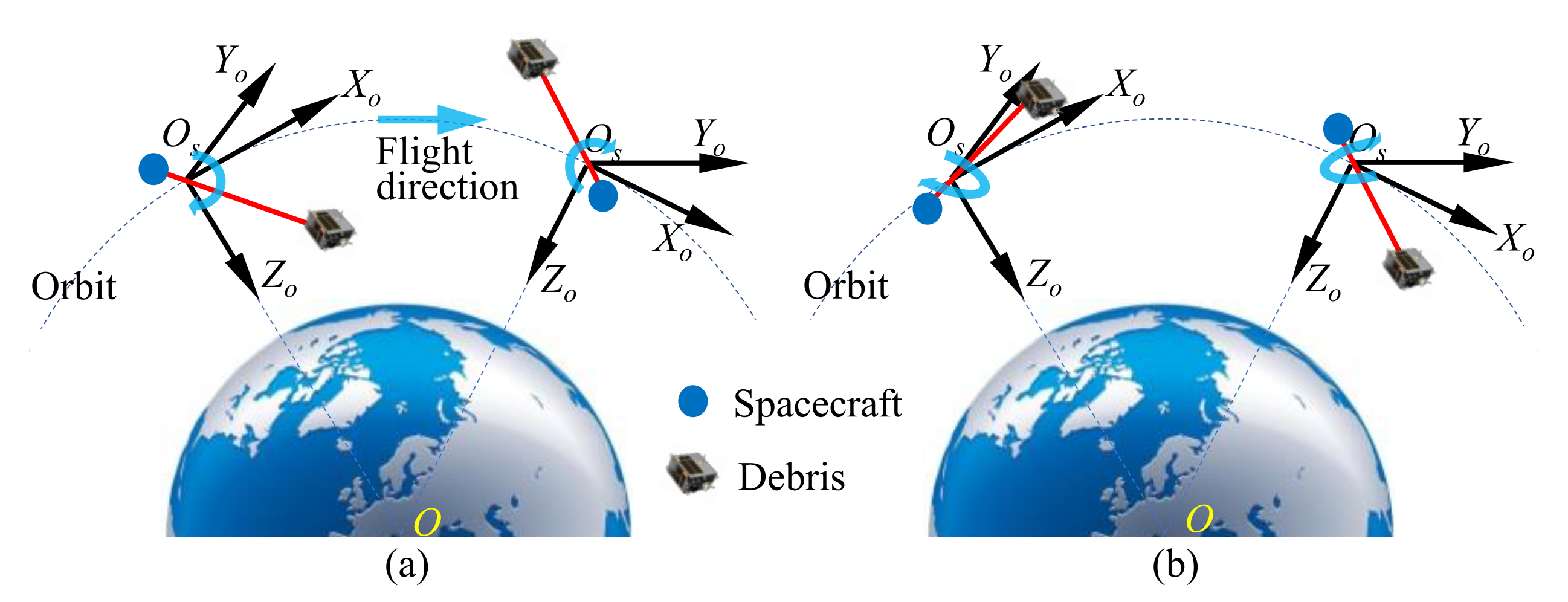
As depicted in Figure 1, the geocentric inertial system O X Y Z , the orbital frame O s X o Y o Z o , and the geomagnetic distribution coordinates O s X m Y m Z m are defined here to describe the spacecraft-debris deorbiting system. Origins O and O s are the mass center of the Earth and spacecraft, severally. The X axis is directed toward the vernal point Y, while the Z axis is the Earth’s rotation axis in a positive direction. The Y o axis is aligned with the opposite direction of the normal of the orbital plane, and the Z o axis is directed from the spacecraft to the Earth’s center. The axes X m and Y m point to the geographic north and east, respectively. The third axis X, X o and Z m complete an orthogonal right-handed system.
The orbital parameters are defined here. i is the orbital inclination. α is the right ascension. Ω is the right ascension of ascending node. f is the true anomaly. u is the argument of ascending node. κ = α Ω is the projection angle of u on equatorial plane.
The conversion matrix of geomagnetic distribution coordinates O s X m Y m Z m to orbital frame O s X o Y o Z o is given by [31]
R o m = sin i cos κ 1 sin 2 i cos 2 κ 0 1 sin 2 i cos 2 κ sin i cos κ 0 0 0 1

2.2. Deorbiting Principle

To deorbit a LEO debris, an amount Δ V is required to decrease the semimajor axis of SD item, namely altering the perigee height into the dense atmosphere to drag the SD to reenter. Assuming the initial orbit of SD is an elliptical orbit, the minimum Δ V for changing the perigee altitude is given by Equation (2).
Δ V = 2 μ R p 1 R a R a + R p 1 2 μ R p 2 R a R a + R p 2
where R a is the apogee altitude of the initial or reentered orbit. R p 1 and R p 2 are the perigee altitude of the initial and reentered orbit, severally.
The following will expound on how to solve for the above Δ V by the GME propulsion approach. Current loops mounted on a satellite body generate a magnetic dipole moment m , and then the magnetic torque resulting from the interaction between m and ambient magnetic field will act on the spinning tethered spacecraft system. The magnetic torque is given by
τ = m × B
where τ is the magnetic torque. m is the magnetic moment carried by the spacecraft, and B is the geomagnetic field intensity.
On the one hand, according to Equation (3), the strength of τ depends not only on the magnitude of m , but also on its orientation relative to the direction of B . A debris–spacecraft configuration is formed after capturing the targeted SD, as depicted in Figure 2. Then, based on the knowledge of the direction of ambient magnet field, the orientation of the m mounted on the rotatable deorbitng part is actively controlled to act a continuous torque on the system, thereby accelerating the rotatable deorbitng part. This accelerating effect can be gradually accumulated over time for the growth on the angular momentum of system, and is defined as the GME effect given by
E = 0 N g T o τ d t
where E is the accumulated angular momentum. T o = 2 π a 3 μ is the orbital period. a is the semimajor axis, and μ = 398600.4 × 10 8 m 3 s 2 is the geocentric gravitational constant. N g is the cumulative number of T o .
On the other hand, the angular kinetic energy E is exchanged into the linear kinetic energy through the deorbitng part, and is further stored for the linear velocity increment Δ V g of SD. As presented in Figure 3, the debris–spacecraft configuration system is simplified as a dumbbell model [34], where the two are considered a lumped mass, and they are configured by a rigid deorbiting part with a length of L c and without mass. Then the moment of inertia (MoI) I c , the system about its mass center (i.e., the rotation center in Figure 3), can be obtained and is the sum of MoI of the spacecraft and debris, i.e., I c = m s L s 2 + m d L d 2 . The influence of the gravity gradient torque, aerodynamic drag torque, etc., is ignored here. From Equation (4), the angular momentum change of the system propelled by the magnetic torque τ (Equation (3)) satisfies the following equation according to the integral form of angular momentum theorem [35].
( m s L s 2 + m d L d 2 ) ω = E
where m s and m d are the masses of the spacecraft and debris. L d and L s are the rotation radii of the debris and spacecraft, respectively, and L c = L d + L s . ω is the rotational angular velocity vector.
Then the Δ V g by GME propulsion for N g orbital periods can be obtained.
Δ V g = 0 N g T o m × B d t m d L c
When Δ V g Δ V , the SD object can be released in the reverse tangent direction of the flying orbit. The debris will finally reenter due to the dense atmosphere, and the LEO debris propellantless deorbiting activity is completed.
In a word, the whole deorbiting process is the LEO GME harvesting, exchange, storage, and release. It can be seen from Equation (6) that deorbiting debris in a LEO can be accomplished in limited orbital periods, essentially a process of time for energy.

2.3. Geomagnetic Field Model and Its Torque Effect

The Earth’s magnetic field changes continuously and unpredictably on all timescales, so the International Geomagnetic Reference Field (IGRF, a set of spherical harmonic coefficients) is produced to describe the large-scale, time-varying portion of it. In addition, the dipole model is often used to approximate the geomagnetic field by a dipole with the center coinciding with the center of Earth and the dipole axis inclined with respect to the polar axis. The descriptions of the geomagnetic field in the geomagnetic distribution coordinates are given by
B x = μ 0 m e cos φ 4 π r 3 B y = 0 B z = μ 0 m e sin φ 2 π r 3 B t = B x 2 + B z 2 = μ 0 m e 4 π r 3 1 + 3 sin 2 φ
where B t is the total intensity of the geomagnetic field. m e = 8.0 × 10 22 Am 2 is the Earth’s magnetic moment. φ is the geocentric latitude. r is the geocentric distance. μ 0 = 4 π × 10 7 N · A 2 is the permeability of the vacuum.
Dr. Liu [36] demonstrated that the components of intensity and gradient of the simplified dipole model have the same variation regularity and similar numerical distribution with those of the actual data-based IGRF model. Considering the extremely simplified expressions and efficient calculation accuracy, the dipole model is used in the following mechanism establishment and theoretical derivation, and the IGRF model is only used in the simulations verification in Section 3. What is more, the effect of the linear velocity increment by GME propulsion for N g orbital periods is not affected by the high-accuracy or simplified geomagnetic computational model. There is only a slight difference between the numerical results of the angular momentum accumulation of the two models, and it is shown in the following simulations.
From Equation (7), the torque τ m of a magnetic moment m interacting with geomagnetic field is given by Equation (8) in the geomagnetic distribution coordinates.
τ m = m y B z m z B x m x B z m y B x
where m x , m y , and m z are the components of m in geomagnetic distribution coordinates.
Then, according to Equations (1) and (7), the torque τ o in orbital coordinates is depicted by
τ o = R o m τ m = m y B z sin i cos κ + m z B x m x B z 1 sin 2 i cos 2 κ m z B x m x B z sin i cos κ m y B z 1 sin 2 i cos 2 κ m y B x

2.4. Directional Energy Storage Mechanism and Strategy

The above Equations (4) and (8) indicated that the direction of m needs to be controlled actively and continually with the orientation change of B during the whole process of the on-orbit energy storage. Due to the presence of coupling among the Earth’s magnetic field, flying orbit, and spacecraft attitude, the rotation direction by GME propulsion should be consistent with the Y o - or Z o -axis of the orbital coordinates to stabilize the attitude of the spacecraft and deorbit the SD, as illustrated in Figure 4. By this way of directional energy storage, the required Δ V for the space debris deorbiting can be effectively obtained.
When the controllable magnetic moment of spacecraft keeps perpendicular to the local magnetic intensity, the GME propulsion can always come out with the maximum torque to guarantee the rapid and continuous accumulation of angular momentum for the debris–spacecraft configuration system. There are, therefore, two different moment control strategies for the Y o and Z o axes directional energy storage, respectively. From Equation (7), we know that B is always in the X m O s Z m plane of geomagnetic distribution coordinates. Hence, the magnetic moment of the two strategies should always be in the X m O s Z m and X m O s Y m planes, respectively, and the magnetic moment of the Z o -axis directional strategy keeps perpendicular to the local magnetic intensity in the X m O s Z m plane, as shown in Figure 5, where C _ m x , C _ m y , and C _ m z are the controlled components of spacecraft magnetic moment in O s X m Y m Z m coordinates.
In Figure 5a ( 90 u 90 ), the angle between B and B z is d, then the relationship among all components of B and m is given by
tan d = C _ m z C _ m x = B x B z C _ m y = 0 C _ m x 2 + C _ m z 2 = | m | 2
Substituting Equation (7) into Equation (10), the controlled components of the spacecraft magnetic moment m are given by
C _ m x = B z B t = 2 sin φ | m | 1 + 3 sin 2 φ , C _ m y = 0 , 90 u 90 C _ m z = B z B t = cos φ | m | 1 + 3 sin 2 φ ,
The same procedure can be easily adapted to obtain the controlled components for the case of 90 u 270 , and the result has the equal value but opposite symbol with that of the case of 90 u 90 . Hence, the strategy of the GME storage at Y o -axis is given by
C _ m x = 2 sin φ | m | 1 + sin 2 φ , 90 u 90 2 sin φ | m | 1 + sin 2 φ , 90 u 270 C _ m y = 0 C _ m z = cos φ | m | 1 + sin 2 φ , 90 u 90 cos φ | m | 1 + sin 2 φ , 90 u 270
In Figure 5b, the strategy of GME storage at Z o -axis is obtained easily by Equation (13). When C _ m y is positive, it means that the magnetic moment always points to east, and the GME is stored at the Z o -axis; otherwise, the magnetic moment always points to west, and the GME is stored in the negative direction of the Z o -axis.
C _ m x = C _ m z = 0 C _ m y = ± | m |
Furthermore, when the real data-based and high-precision IGRF model is applied to the strategy, the directional energy storage strategy at the Y o -axis, Equation (12), will be adaptively rewritten by Equation (14), where the geomagnetic intensity parameter of IGRF model, not the geocentric latitude φ of the dipole model, is used for on-orbit strategy adjustment.
C _ m x = B z g | m | ( B x g ) 2 + ( B y g ) 2 + ( B z g ) 2 , 90 u 90 B z g | m | ( B x g ) 2 + ( B y g ) 2 + ( B z g ) 2 , 90 u 270 C _ m y = 0 C _ m z = B x g | m | ( B x g ) 2 + ( B y g ) 2 + ( B z g ) 2 , 90 u 90 B x g | m | ( B x g ) 2 + ( B y g ) 2 + ( B z g ) 2 , 90 u 270
where B x g , B y g , and B z g are components of B under the IGRF model in the geomagnetic distribution frame. Equation (15) describes the IGRF model in geomagnetic distribution coordinates, and is the combination of the 13th order spherical harmonics expression and Gauss coefficient.
B x g = n = 1 13 m = 0 n ( R e r ) n + 2 A n m · d P n m ( cos θ ) d θ × 10 9 B y g = n = 1 13 m = 0 n ( R e r ) n + 2 m B n m sin θ · P n m ( cos θ ) × 10 9 B z g = n = 1 13 m = 0 n ( R e r ) n + 2 ( n + 1 ) A n m · P n m ( cos θ ) × 10 9
where A n m = g n m cos ( m λ ) + h n m sin ( m λ ) , B n m = g n m sin ( m λ ) h n m cos ( m λ ) . R e is the Earth’s radius. θ is the geocentric colatitude. λ is the longitude. g n m and h n m are the Gauss coefficient changing with time, and P n m ( cos θ ) is the n-order m-th Legendre function.

2.5. Energy Storage and Deorbiting Capability

Using the above strategy, Equation (12) or Equation (13), the angular kinetic energy is injected into the rotational debris-spacecraft configuration system. Substituting Equation (9) into Equation (4), the stored energy E g in N g orbital periods is given by Equation (16) or Equation (17), respectively. No matter which strategy is adopted, the energy stored under dipole model of the other two orbital directions is zero in one orbital period.
E g = 0 , μ 0 m e | m | 0 N g T 0 1 + 3 sin 2 φ cos i cos κ d t 4 π r 3 , 0 T
E g = 0 , 0 , μ 0 m e | m | 0 N g T 0 cos φ d t 4 π r 3 T
Hence, from Equations (6), (16), and (17), the total velocity increment Δ V g by GME propulsion for N g can be given as the following two formulas, where Equations (18) and (19) are the linear velocity results of energy storage at the Y o and Z o axes, respectively.
Δ V g = μ 0 m e | m | 0 N g T 0 1 + 3 sin 2 φ cos i cos κ d t 4 π r 3 m d L c
Δ V g = μ 0 m e | m | 0 N g T 0 cos φ d t 4 π r 3 m d L c
By a brief analysis of Equations (18) and (19), it can be shown that the deorbiting capability of two directional strategies can cover the entire LEOs. The directional Y o -axis strategy cannot be used to equatorial orbit because the geocentric latitude φ is always equal to zero, namely sin φ = 0 of Equation (18). The directional Z o -axis strategy can be used for all LEO orbits, and has a distinct advantage on equatorial orbit.

3. Simulation Results and Discussion

To verify the approach’s capability of GME storage (i.e., angular momentum accumulation) and deorbiting (i.e., velocity increment), we perform simulations under circular LEOs with different altitudes below 1000 km and inclinations. The continuous stored angular momentum on a elliptical orbit is on the order of that of the circular LEOs within one orbital period, and there are only minimal differences between them due to the geomagnetic intensity difference caused and changed by altitude below 1000 km. What is more, Matteo and Morton [37] indicated that the satellite data-based IGRF model is within 1% accuracy of the measured ionosphere B field orbiting between 200 and 1000 km, 92.80% of the time, even in more geomagnetically active conditions. The magnetosphere of Earth begins at approximately 1000 km and extends thousands of kilometers into space [38]. Affected by the solar wind, the Earth’s magnetic field lines can be significantly distorted, and the field is extremely unstable in the region above 1000 km [39]. Consequently, for above 1000 km, the proposed strategies based on the IGRF and dipole model may not calculate the actual geomagnetic field strength correctly in real time when considering the real space environment. Therefore, it is not clear whether the above strategies can be applied to the LEO region above 1000 km, and we do not carry out the corresponding verification simulations here.
We take the perigee altitude of 150 km as the targeted deorbiting height. The existing technology can generate the 10 3 Am 2 level stable, controllable, light-weight, and low-power magnetorquer, so we set the deorbiting spacecraft’s magnetic moment with 10 3 Am 2 level. Set the mass of the deorbiting spacecraft to 200 kg, and its area–mass ratio and drag coefficient to 0.003 and 2.2, respectively. Set the right ascension of ascending node Ω , argument of perigee ω , and true anomaly f to 0. The NRLMSISE00 atmospheric model is applied to the calculation of the atmospheric density in the following simulations. We conduct simulations under both dipole and IGRF models, and use the IGRF model-based and higher precision results for verification.
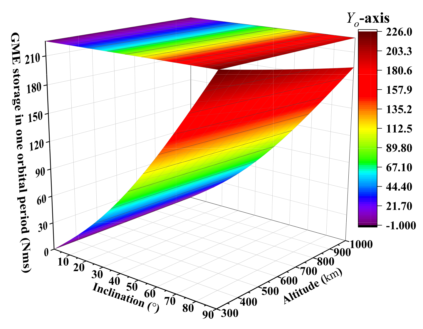
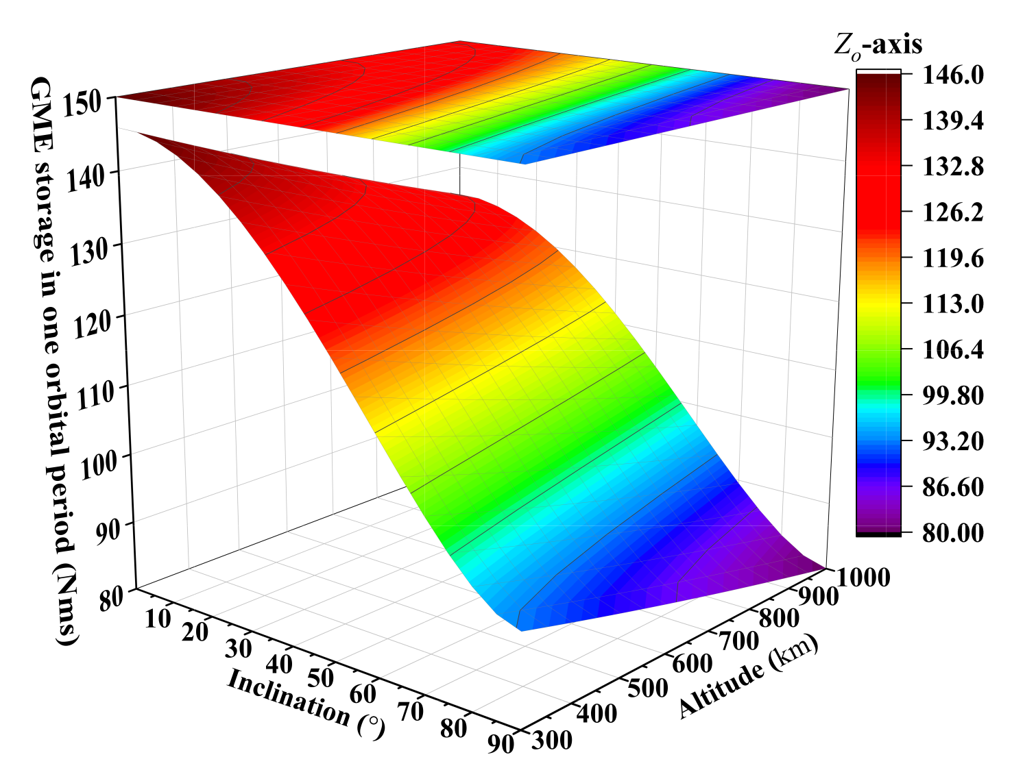
Results of angular momentum accumulation for one orbital period ( N g = 1 ) under the magnetic moment m = 10 3 Am 2 are presented in Figure 6, Figure 7, Figure 8 and Figure 9, and demonstrate the following:
  • The GME propellant approach can be applied to the region of LEO below 1000 km with different altitudes and inclinations, and it is consistent with the analysis results in Section 2.5. As seen in Figure 6 or Figure 7b, the strategy at the Y o -axis, Equation (12) or (14), has an obvious advantage on the orbit with a large inclination, but does not have the energy storage capacity for equatorial orbit. From Figure 8 or Figure 9c, the strategy at the Z o -axis, Equation (13), can be used for the entire LEO below 1000 km. With the combination of Figure 6, Figure 7b, Figure 8 and Figure 9c, we know that when i > 49 . 16 , the strategy of GME storage at Y o -axis is adopted; otherwise, the choice of strategy at the Z o -axis is reasonable. So the Figure 10 is presented to show the energy storage capability of the GME propellant approach.
  • The GME propellant approach has a potent capability of angular momentum accumulation (see Figure 10). Under a magnetic moment of 10 3 Am 2 , it can accumulate the angular momentum at the level of 10 1 to 10 2 Nms in one period (about 100 min) and more than 10 3   Nms in one day. At the same power consumption, the approach can provide much higher energy storage capability than the maximum 10 2 to 10 3 Nms level of typical energy storage/exchange devices including control moment gyroscopes and reaction wheels, etc., for a spacecraft [40], and has no momentum saturation due to the continuous accumulation of external magnetic torque.
  • Compared with the existing propellantless deorbiting methods, the proposed approach has higher efficiency and lower dependence on the scale for the LEO debris deorbiting [41,42]. To deorbit a LEO 100 kg · m (product of debris mass and scale of deorbiting mechanism) debris, days to weeks (tens to hundreds of orbital period) of preparation is required with the existent magnetorquer technology, as depicted in Table 1.

4. Development of Ground Experimental System

To demonstrate the approach’s feasibility and practical potential, an elementary ground-based realization is indispensable. We focus on the following points to design a ground-based system to provide evidence for the continuous cumulative effect of rotational angular momentum in LEO, namely the LEO GME effect. An air-bearing multi-dimensional microgravity simulator supports the simulated debris-spacecraft configuration system, and an electromagnetic coil generates the controllable magnetic moment of the spacecraft. Given the fixed turns N and area S of the coil, the strength of the magnetic moment is proportional to the input current I from Equation (20). So we obtain the different magnetic moments (torque) by inputting different constant direct currents to the coil with a fixed N S .
m = I S d S = N I S
We conduct the ground experiment at a fixed site, so the geomagnetic field intensity is a constant vector, different from the on-orbit fact of changing intensity. Nevertheless, this will not affect the verification of the LEO GME effect, and will further simplify the control strategy for generating the magnetic moment. The maximum torque output of the electromagnetic coil is guaranteed by generating a directional magnetic moment always perpendicular to the direction of the geomagnetic field at the experimental site. The research on the attitude of the dynamical behavior influenced by the mass distribution of the system is not the focus of this paper, so we can adopt the overall mechanical structure with a horizontal mass-symmetric distribution. The air-bearing simulator supports the metacenter (not the center of mass) of the ground system, and the metacenter height shall be as high as possible to ensure the noticeable continuous accelerating effect of debris. The connecting line between the metacenter and centroid is perpendicular to the horizontal ground under the static condition, and is defined as the rotation axis of energy storage. Hence, only considering the horizontal motion, the maximum torque is generated by the magnetic moment vector in the horizontal plane always perpendicular to the horizontal north–south direction of the geomagnetic field. The GME effect will rotate the simulated debris in the horizontal plane.
However, as the debris rotates, the magnetic moment will rotate at the same speed. To ensure the output of (maximum) torque, we must continually alter the direction of the magnetic moment by a control system with a high response, and it cannot be achieved by one coil. What is worse, the spacecraft body will also spin in the opposite direction, which we do not want to see in the following experiments and actual flights. To stabilize the spacecraft attitude and decouple the rotation of debris and the spin of spacecraft body, we introduce a momentum exchange device to connect the spacecraft and rotatable part for debris deorbiting. The stator of the momentum exchange device and the electromagnetic coil for generating the changing magnetic moment are fixed to the spacecraft body, and the rotor is fixed to the rotatable part, as illustrated in Figure 11.

4.1. Modeling and Control

Now we can divide the ground system into two parts: part one—spacecraft body, magnetic moment, and stator of momentum exchange device; and part two—rotor of momentum exchange device, rotatable deorbiting part, and debris. Assuming zero initial angular momentum of the system, once the angular velocity of part one about the system’s rotation axis is non-zero under the GME effect, it indicates the GME is obtained. Simultaneously, by the active and precise control of the rotor’s torque, the momentum exchange device exchanges the energy to part two of the system to achieve no change in the coil/spacecraft attitude and continuous accelerating rotation of the rotatable part. In this way, part two of the system shall continuously harvest, exchange, and store the GME.
The total angular momentum of the system about the rotation axis can be written as
h t o t a l = h 1 + h 2
where h 1 and h 2 are the angular momentum of the two parts of the system, respectively.
According to the theorem of angular momentum, the ground system satisfies
h ˙ t o t a l = J 1 ω ˙ 1 + J 2 ω ˙ 2 = τ g + τ d + τ A
where J 1 and J 2 are the moment of inertia of the two parts of system, and ω 1 and ω 2 are the corresponding angular velocity about the rotation axis, respectively. τ g is the magnetic torque, and τ d is the uncertain disturbance torque of system. τ A is the aerodynamic drag torque, and is given by
τ A = k A ω 2 2 ω 2 ω 2
where k A is the coefficient of aerodynamic drag torque, and its value is related to the windward area, overall shape and surface smoothness of the part two of system.
From Equation (22), we design a closed-loop control system, and define the angular velocity ω 1 r of the part one of system as the input signal. The actuating error signal, difference between ω 1 and its measured feedback value ω 1 c , are fed to the controller so as to bring the output signal ω 1 c to the desired value, as detailed in Figure 12. A PID controller is used. e a is the applied voltage of momentum exchange device, and L a and R a are the inductance and resistance, respectively. k τ and k b are the torque constant and back EMF constant of momentum exchange device, respectively. τ m is the output torque of momentum exchange device. f a is the viscous-friction coefficient of part two of the system.

4.2. Simulation

The simulation examples are carried out to confirm the validity of the control model, and are designed according to the actual condition of the following proof-of-principle experiments in Section 5. Four simulation results are presented here. The magnetic torque τ g exerted on part one of the system is set as 0.0755   Nm , 0.1115   Nm , and 0.1859   Nm respectively, which are perpendicular to the ground. The simulation duration of the examples is set to 900   s . Given the zero initial condition of ω 1 r = 0 and by adjusting the PID parameter, we obtain the results of the angular velocity of part two of the system, the angular velocity, angular displacement, and angular acceleration of part one, as shown in Figure 13. The results suggest the following.
  • The system can be well controlled with good robustness, and has great performance in both steady and transient responses. As seen in Figure 13a, the angular velocity of part two (debris) increases with time, and does not oscillate, finally converging to a constant.
  • The attitude holding of part one (spacecraft body) is well satisfied, which is in good agreement with our expectations. As depicted in Figure 13b,d, the peak of angular velocity and acceleration occurs only at the initial time, and the angular displacement is approximately from 5 . 9 to 9 . 7 , shown in Figure 13c.

4.3. Ground Experimental System

Figure 14 is the developed ground experimental system, and all components are symmetrically arranged and made of the non-magnetic material of aluminum alloy, except for the coiling of the magnetic moment. The rotation axis of the momentum exchange device is perpendicular to the horizontal ground, and goes through the support point of the spherical 3-axis air bearing. Four copper wire coils are used, and are characterized by the total amount of N S = 900 · 1 m 2 for the 10 3 to 10 4 Am 2 generation of the magnetic moment. The radius of the rotatable part is 1 m . To avoid interference from the system stability control difficulty caused by irregular debris, the debris at the two ends of the rotatable part uses a standard shape, and the mass of the two pie-shaped debris is 1 kg . Moreover, the end of the rotatable part passes directly through the mass center of the debris to ensure overall symmetry. A multi-axis microelectromechanical systems gyroscope is used as the angular velocity measuring device of the spacecraft body. As discussed above, only the z-axis (i.e., vertical rotation axis) measured data are fed to the control modular in the following experiments.

5. Proof-of-Principle Experiment

Experiments are carried out to validate the LEO GME effect and achieve the GME harvesting, exchange and storage.
We chose an indoor experimental site in Beijing ( 116 . 69 E , 40 . 33 N ), and the measured value of the horizontal north–south strength of the geomagnetic field stabilizes at 20645.8565 nT based on the repeated measurements. So the coils can provide a magnetic torque of 0.1 Nm -level (see Table 2). The calibrated resistance torque of the air bearing is 10 4 Nm , so it can be ignored, compared to the magnetic torque. The uncertain disturbance torque caused by the asymmetric wiring and mounting of coils and control modular is an important consideration for the GME effect verification, and shall be calibrated in the following experiments.

5.1. GME Harvesting Experiment

The primary concern of GME effect verification is to ensure that the system can harvest GME by the electromagnetic coil, and the effect of magnetic torque, not the disturbance torque, is the main excitation of energy harvesting. We perform the GME harvesting experiment by only powering the electromagnetic coils. The initial direction of magnetic moment (spacecraft body) is close to the horizontal east–west direction of the geomagnetic field, and the attitude of spacecraft body remains stationary for a long period without external force/torque. Figure 15 shows the attitude changes of spacecraft body at the different times after the coils are electrified with DC constant current of 10   A ( τ g = 0.1859 Nm ). The results indicate that, based on the torque effect of the geomagnetic field, the system can harvest GME to rotate rapidly to the geomagnetic north–south direction.

5.2. GME Storage Experiment

5.2.1. Disturbance Torque Calibration

As mentioned above, the maximum magnetic torque exerted on part two of the system is obtained by the magnetic moment pointing to the horizontal east–west direction of the geomagnetic field. So the variation law of the disturbance torque τ d in this direction needs to be clarified before the GME storage experiment. We define the zero initial angle of system attitude as the horizontal east–west direction of the geomagnetic field.
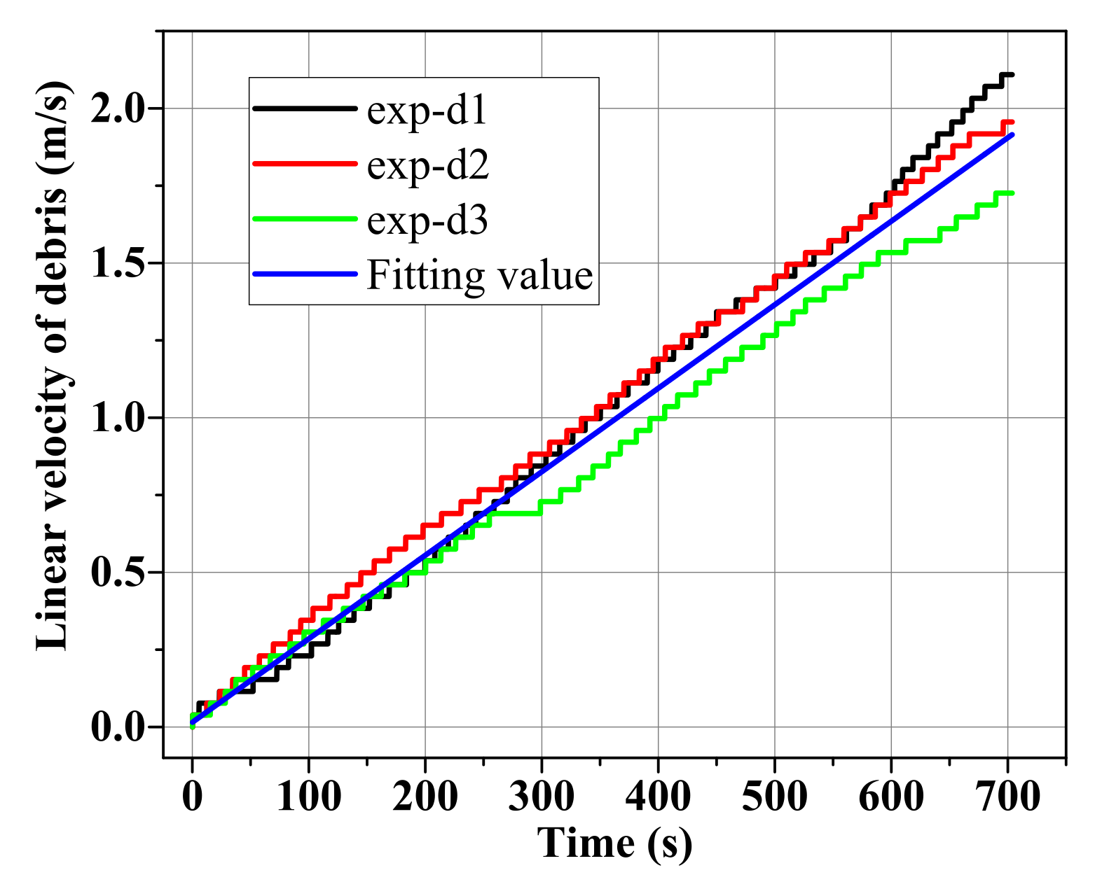
The calibration process of τ d is as follows. We first set the system attitude at the zero initial angle. Then only the momentum exchange device, not the coils, is powered on and actively controlled, and we take the angular velocity of part two of the system that equals zero as the objective throughout the process. Driven by the τ d merely, the rotatable part and debris can be accelerated gradually and continuously. The τ d can be calibrated by the linear velocity of debris. We conducted many experiments in this way. Results of the three experiments marked as exp-d1, exp-d2, and exp-d3 are detailed in Figure 16, where the debris’ linear velocity is calculated from the feedback data of the momentum exchange device.
The results show that the final velocity of the three experiments is small, especially in the initial stage, and the debris’ velocity almost increases linearly as the time increases, except for a few abnormal points. We therefore consider the angular acceleration of debris as a constant. Based on the mean value of three results, we obtain the linear fitting velocity depicted in Figure 16, i.e., Equation (24). Then we can obtain ω ˙ 2 = 0.0027 rad · s 2 .
v d = 0.0027 t + 0.0197
where v d is the linear fitting velocity of debris, and t is the time.
In this experiment, the magnetic torque τ g is equal to zero. The disturbance torque τ d and aerodynamic drag torque τ A are the main excitation source for the linear kinetic energy of debris. Hence, from Equations (22) and (23), Equation (22) is rewritten in this experiment.
J 2 ω ˙ 2 = k A ω 2 2 ω 2 ω 2 + τ d
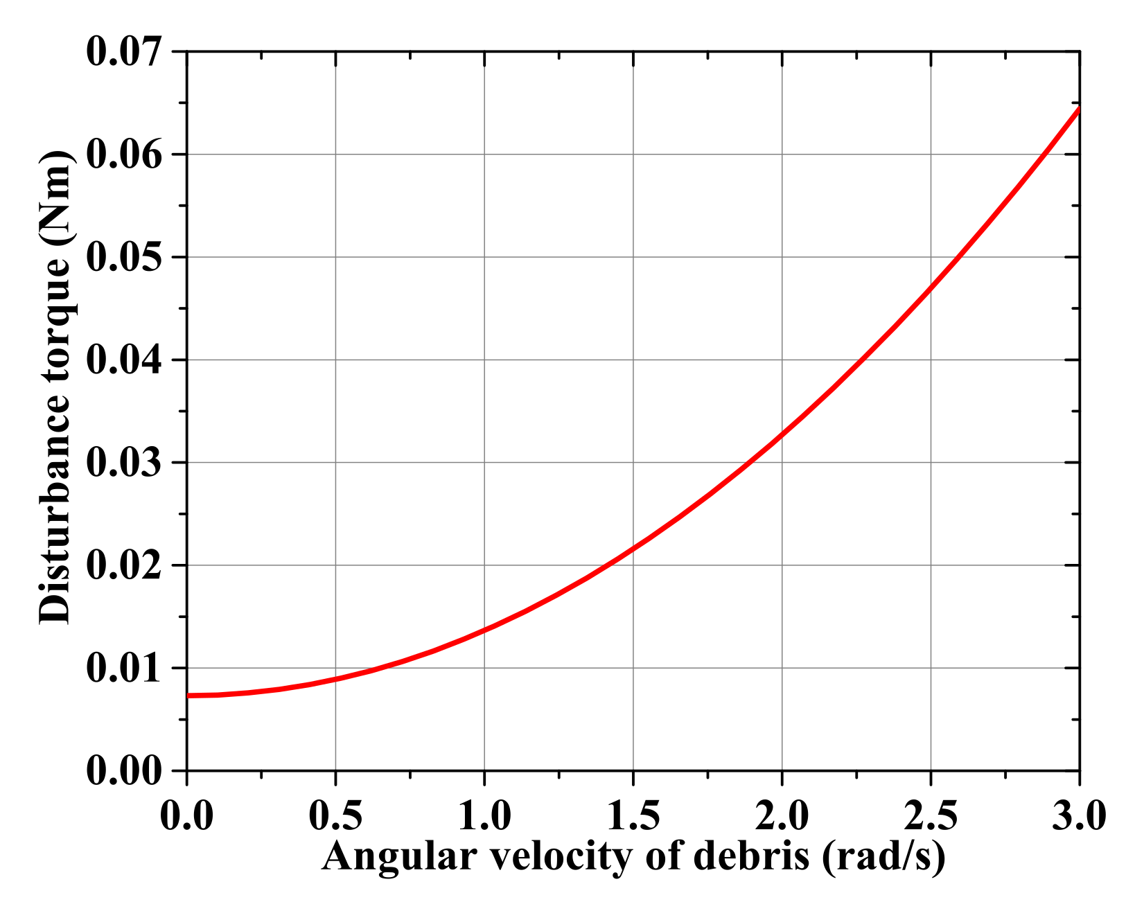
where J 2 = 2.707 kg · m 2 . k A consists of two parts: the torque coefficient of the rotatable part and debris. The rotatable part and debris are cylindrical in shape, and their drag coefficient belongs to the drag coefficient of flow around the circular cylinder. k A is mainly related to the Reynolds number and the length–diameter ratio [43]. In this experiment, the Reynolds area is from 10 4 to 10 5 , and the length–diameter ratio of the two parts are 100 and 0.13, respectively. By Figure 3 in Ref. [43], the drag coefficient of the rotatable part and debris are about 1.035 and 0.0019, and further obtain the k A = 6.347 × 10 3 , where the air density in the site is 1.205 kg / m 3 (20 °C). Substituting k A and ω ˙ 2 into Equation (25), the relationship of τ d and ω 2 is given by Equation (26), and reflected in Figure 17.
τ d = 6.347 × 10 3 ω 2 2 + 7.308 × 10 3
It turns out that the system’s disturbance torque increases with the angular velocity of the rotatable part and debris. It is on the order of 0.01 Nm , and is far less than the magnetic torque in a certain condition. Especially at the initial time of an experiment, the disturbance torque is not the primary source of angular momentum accumulation for the system, which is an essential premise for the following GME storage experiments by this ground system.

5.2.2. GME Storage Experiment

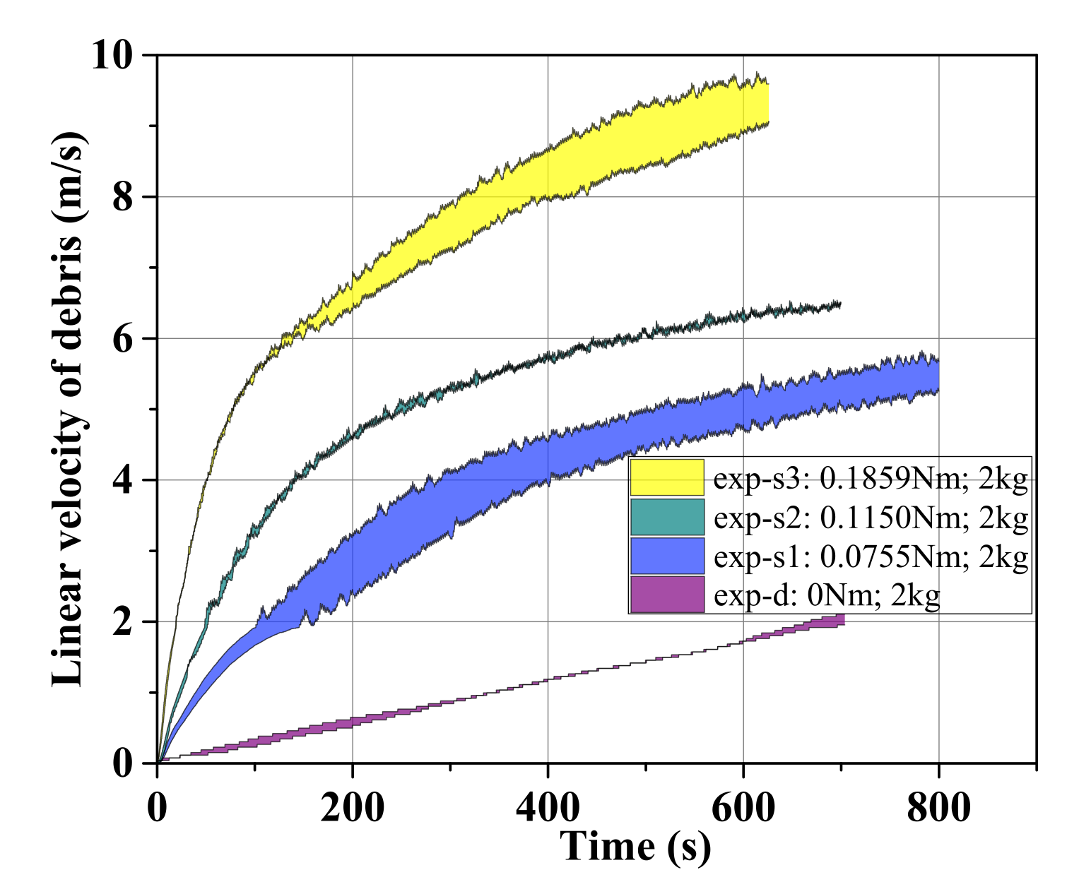
This experiment is intended for the verification of the continuous LEO GME effect. The initial direction of the coil and spacecraft body is set perpendicular to the geomagnetic north–south direction. Given a constant DC current to the coils and the corresponding PID control simulated in Section 4.2 to the momentum exchange device, then the generated magnetic moment/torque is the maximum, and the clear continuous cumulative effect from GME can be guaranteed in each experiment. We carry out many energy storage experiments in this way, and the parameters and results are shown in Table 3, where Δ V m a x is the final maximum linear velocity of debris, and the data marked as exp-d of the last row are the parameters and the result of disturbance torque calibration in Section 5.2.1. All experiments are repeated more than four times. We summarize all the experimental results, and show the error band of the exp-s1 to exp-s3, presented in Figure 18.
The result demonstrates the following:
  • The principle of GME storage is feasible. The GME harvesting, exchange, and storage can be achieved by the ground system based on electrical energy. That is to say, the proposed GME propulsion approach, the conversion of rotational angular momentum into linear momentum, can realize the system energy storage.
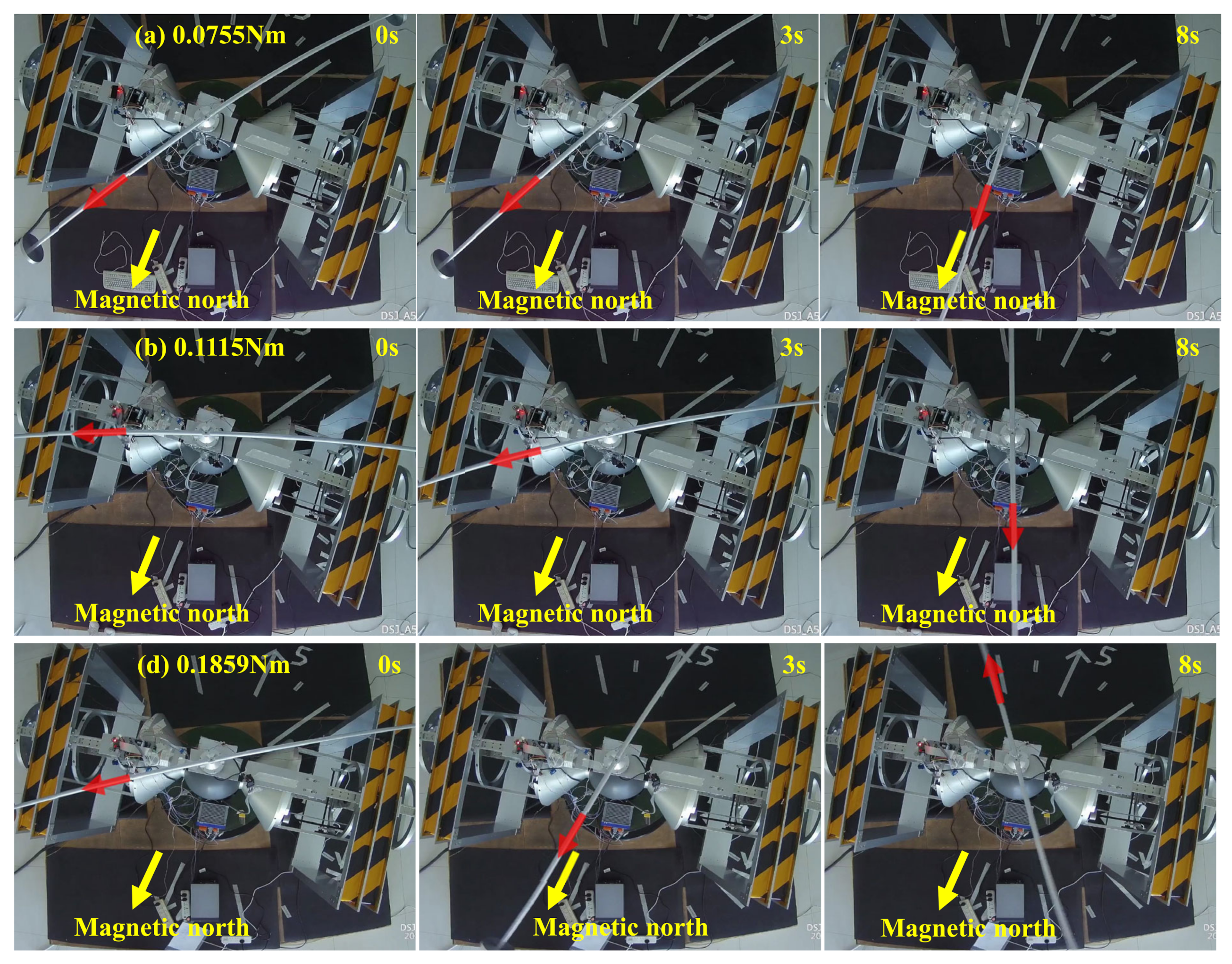
  • The effect of continuous GME storage is noticeable. After the coils and momentum exchange device are electrified, there is a clear sustained acceleration tendency of debris, and the tendency is apparently different under different DC current (magnetic torque), as seen in Figure 19. In about 10 min, the linear velocity of the two debris reaches the final Δ V m a x of 9.6 m / s with a total 2 kg debris.
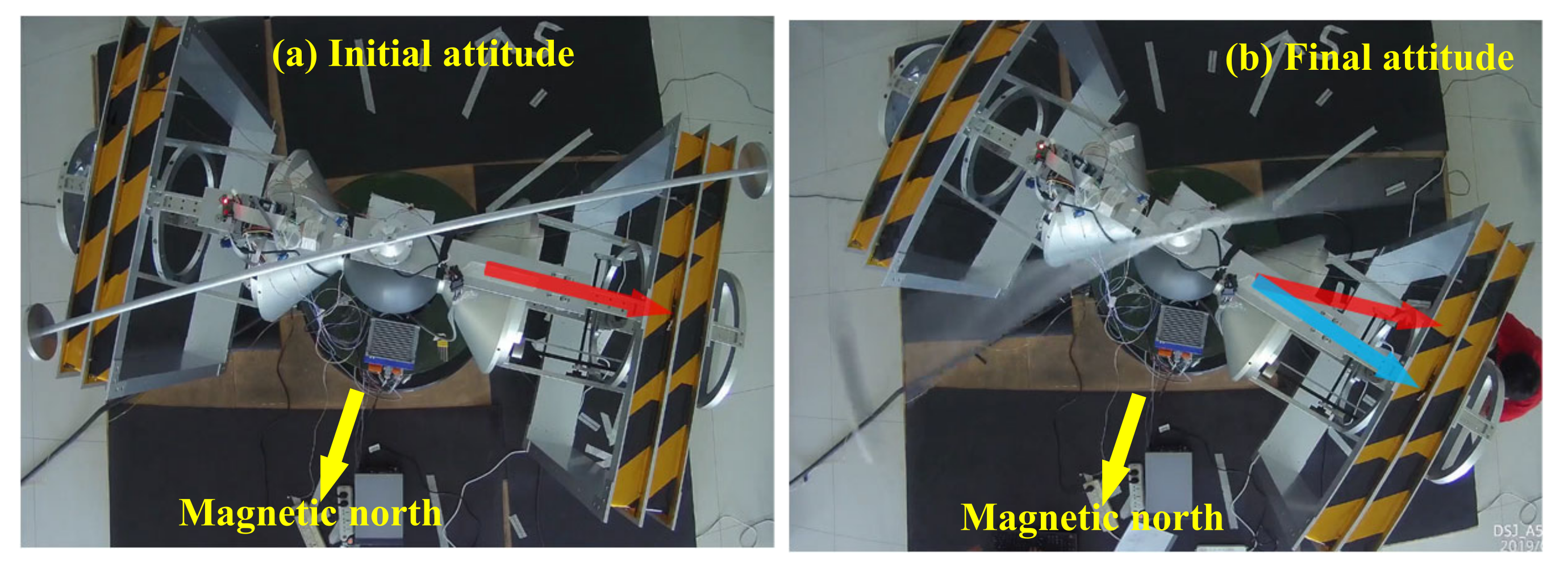
  • The attitude holding of the spacecraft body and magnetic moment is well satisfied, consistent with the simulation results. It indicates that the proposed GME propellant approach has remarkable engineering realizability. Taking the experiment of exp-s3 as an example, the angle changes of spacecraft body attitude are about 12 between the initial position and the final position, as given in Figure 20, and is in good agreement with the simulation result of 8 . 8 . The angle changes can be avoided by debugging a better control system or the active attitude adjustment of the spacecraft.
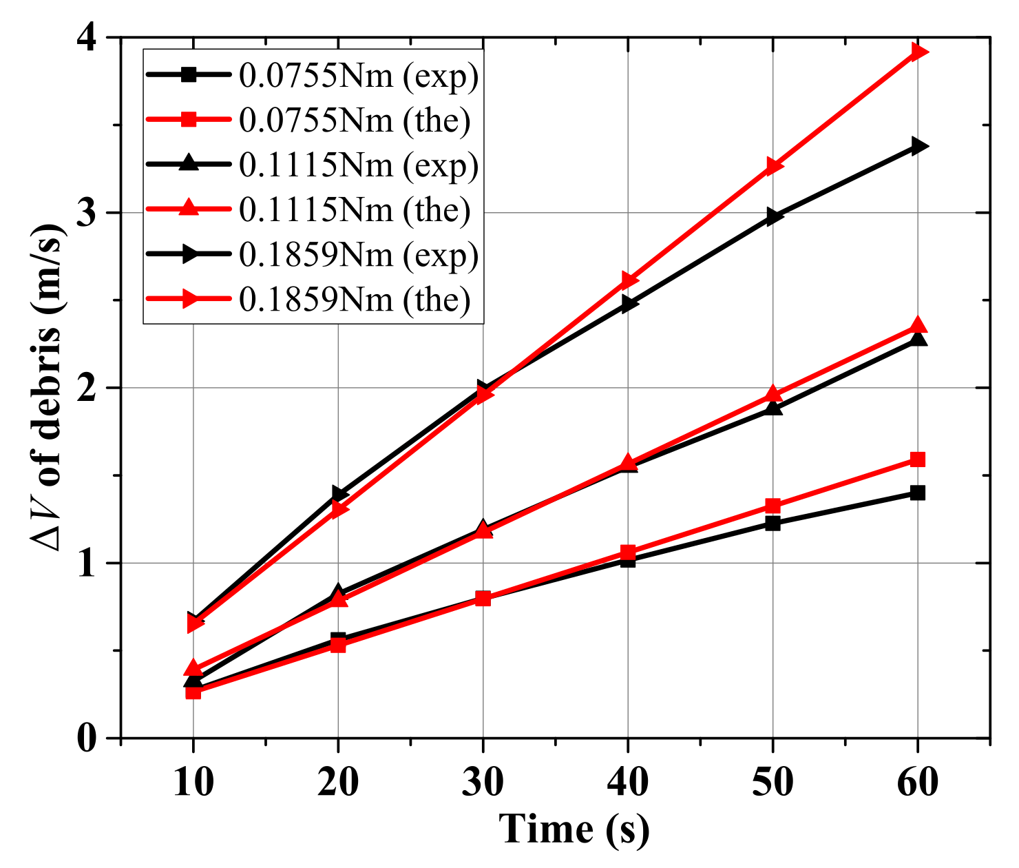
  • The measured value of velocity increment coincides well with the theoretical calculation, and the mechanism of directional energy storage is verified. At the beginning of each experiment, the velocity of the debris is relatively little, and the effect of the disturbance torque and air aerodynamic torque on the angular momentum accumulation of the system is negligible compared with that of the magnetic torque. Hence, the measured Δ V in the initial 60s is taken out here to compare with the theoretical value (see Table 4 and Figure 21). The experimental Δ V is in well accordance with the theoretical result, and with the increase in velocity, the deviation of them gradually appears due to the effect of the disturbance torque and air aerodynamic torque.
  • The LEO GME utilization in space is elementarily verified.

6. Conclusions

This paper proposes a novel approach to LEO debris deorbiting, using no propellant based on the energy source of the Earth’s magnetic field. The mechanism of the directional GME storage is established to achieve efficient momentum accumulation and on-orbit attitude holding of deorbiting spacecraft, and the presented two storage strategies are applicable to debris in LEO at different inclinations. The theoretical analysis and simulations support that the approach can be used in the region with a stable geomagnetic field below 1000 km and has a strong deorbiting capability of 10 kg- to 100 kg-level debris within days to weeks with the existing magnetorquer technology. It is essentially a process of time for the energy of a system based on the continuous accumulation of external torque, and there is no saturation caused by superfluous energy in the proposed approach. Compared with existing propellantless deorbiting methods, it has more suitability for orbital parameters, faster deorbiting, and lower dependence on the scale. The ground experimental system for GME effect verification is developed by the innovative design of a reaction momentum exchange device, pushing the limit of the type of typical momentum exchange. Then, proof-of-principle experiments are conducted and validate the LEO GME effect. The experimental results agree with theoretical calculations, and the LEO GME utilization in space is elementarily verified. The GME propellant approach has remarkable engineering realizability and is, therefore, a feasible option for debris removal.
We assume a rigid and massless connection between debris and spacecraft to simplify the two-body configuration system and facilitate theoretical analysis, and use a fixed-length rigid rod to spin the debris in the ground experiments. The connection can be a variable-length space tether in the debris deorbiting mission, and we can gradually lengthen the tether with the increase of the debris’s velocity to restrain the centrifugal overload of the debris within an acceptable range, such as 10 g. Using the variable-length tether can further accelerate the deorbiting of debris, and deorbit larger and heavier debris, the main target of active debris removal now. The superconducting coil can be used to generate the controllable magnetic moment of the spacecraft with the gradual maturity of space superconducting technology. The capability of GME storage and deorbiting, and the deorbiting time will change by orders of magnitude.
The coupling analysis and decoupling control of the orbit, altitude, and rotation of deorbiting spacecraft, and the mission planning method for multi-debris deorbiting are our subsequent research work. The proposed approach can be applied with the existing capturing technologies, and a space-based removal platform using GME will be developed for the practical LEO debris deorbiting shortly. Apart from the LEO debris deorbiting, we can use this cost-effective approach for space-based supplies delivery, transportation, space travel, etc., for years to come.

Author Contributions

Conceptualization, H.Z. and W.L.; methodology, W.L. and G.F.; software, G.F. and C.Z.; validation, G.F., C.Z. and W.L.; formal analysis, G.F. and C.Z.; investigation, G.F. and W.L.; resources, G.F.; data curation, G.F.; writing—original draft preparation, G.F.; writing—review and editing, G.F.; visualization, G.F.; supervision, W.L. and G.F.; project administration, G.F.; funding acquisition, W.L. All authors have read and agreed to the published version of the manuscript.

Funding

This research was funded by the Strategic Priority Research Program of the Chinese Academy of Sciences (grant number XDA17030200); the Program (grant number 1816318TS00100501, 18JSLL0100000505); the Joint Fund of the Chinese Academy of Sciences (grant number 8091A01); and the National Natural Science Foundation of China (grant number 11002143).

Institutional Review Board Statement

Not applicable.

Informed Consent Statement

Not applicable.

Data Availability Statement

The data presented in this study are available on request from the corresponding author.

Conflicts of Interest

The authors declare no conflict of interest.

References

  1. Serebryanskiy, A.; Akniyazov, C.; Demchenko, B.; Komarov, A.; Omarov, C.; Reva, I.; Krugov, M.; Voropaev, V. Statistical analysis of object congestion in the geostationary region. Acta Astronaut. 2021, 182, 424–431. [Google Scholar] [CrossRef]
  2. Shan, M.; Shi, L. Comparison of Tethered Post-Capture System Models for Space Debris Removal. Aerospace 2022, 9, 33. [Google Scholar] [CrossRef]
  3. Feng, G.; Li, W.; Zhang, H. Geomagnetic Energy Approach to Space Debris Deorbiting in a Low Earth Orbit. Int. J. Aerosp. Eng. 2019, 2019, 5876861. [Google Scholar] [CrossRef]
  4. Liou, J.C.; Johnson, N.L. Instability of the present LEO satellite populations. Adv. Space Res. 2008, 41, 1046–1053. [Google Scholar] [CrossRef]
  5. Anz-Meador, P.D. Orbital Debris Quarterly News. 2020. Available online: https://orbitaldebris.jsc.nasa.gov/quarterly-news/ (accessed on 28 June 2022).
  6. Qi, R.; Misra, A.K.; Zuo, Z. Active debris removal using double-tethered space-tug system. J. Guid. Control. Dyn. 2017, 40, 722–730. [Google Scholar] [CrossRef]
  7. Zhang, Z.; Li, X.; Wang, X.; Zhou, X.; An, J.; Li, Y. TDE-Based Adaptive Integral Sliding Mode Control of Space Manipulator for Space-Debris Active Removal. Aerospace 2022, 9, 105. [Google Scholar] [CrossRef]
  8. Shan, M.; Guo, J.; Gill, E. Review and comparison of active space debris capturing and removal methods. Prog. Aerosp. Sci. 2016, 80, 18–32. [Google Scholar] [CrossRef]
  9. Hakima, H.; Emami, M.R. Assessment of active methods for removal of LEO debris. Acta Astronaut. 2018, 144, 225–243. [Google Scholar] [CrossRef]
  10. Mark, C.P.; Kamath, S. Review of active space debris removal methods. Space Policy 2019, 47, 194–206. [Google Scholar] [CrossRef]
  11. Li, S.; She, Y. Recent advances in contact dynamics and post-capture control for combined spacecraft. Prog. Aerosp. Sci. 2021, 120, 100678. [Google Scholar] [CrossRef]
  12. Aglietti, G.S.; Taylor, B.; Fellowes, S.; Salmon, T.; Retat, I.; Hall, A.; Chabot, T.; Pisseloup, A.; Cox, C.; Mafficini, A.; et al. The active space debris removal mission RemoveDebris. Part 2: In orbit operations. Acta Astronaut. 2020, 168, 310–322. [Google Scholar] [CrossRef]
  13. Aglietti, G.; Taylor, B.; Fellowes, S.; Ainley, S.; Tye, D.; Cox, C.; Zarkesh, A.; Mafficini, A.; Vinkoff, N.; Bashford, K.; et al. RemoveDEBRIS: An in-orbit demonstration of technologies for the removal of space debris. Aeronaut. J. 2020, 124, 1–23. [Google Scholar] [CrossRef]
  14. Schaub, H.; Jasper, L.E.; Anderson, P.V.; McKnight, D.S. Cost and risk assessment for spacecraft operation decisions caused by the space debris environment. Acta Astronaut. 2015, 113, 66–79. [Google Scholar] [CrossRef]
  15. Lv, S.; Zhang, H.; Zhang, Y.; Ning, B.; Qi, R. Design of an integrated platform for active debris removal. Aerospace 2022, 9, 339. [Google Scholar] [CrossRef]
  16. Takeichi, N.; Tachibana, N. A tethered plate satellite as a sweeper of small space debris. Acta Astronaut. 2021, 189, 429–436. [Google Scholar] [CrossRef]
  17. Chen, Y.; Huang, R.; Ren, X.; He, L.; He, Y. History of the tether concept and tether missions: A review. Int. Sch. Res. Not. 2013, 2013, 502973. [Google Scholar] [CrossRef]
  18. Spencer, D.A.; Johnson, L.; Long, A.C. Solar sailing technology challenges. Aerosp. Sci. Technol. 2019, 93, 105276. [Google Scholar] [CrossRef]
  19. Rhatigan, J.L.; Lan, W. Drag-enhancing deorbit devices for spacecraft self-disposal: A review of progress and opportunities. J. Space Saf. Eng. 2020, 7, 340–344. [Google Scholar] [CrossRef]
  20. Lu, H.; Li, A.; Wang, C.; Zabolotnov, Y.M. Stability analysis and motion control of spinning electrodynamic tether system during transition into spin. Acta Astronaut. 2020, 177, 871–881. [Google Scholar] [CrossRef]
  21. Aslanov, V.; Yudintsev, V. Dynamics of large space debris removal using tethered space tug. Acta Astronaut. 2013, 91, 149–156. [Google Scholar] [CrossRef]
  22. Fu, B.; Sperber, E.; Eke, F. Solar sail technology—A state of the art review. Prog. Aerosp. Sci. 2016, 86, 1–19. [Google Scholar] [CrossRef]
  23. Zhao, P.; Liu, J.; Wu, C. Survey on research and development of on-orbit active debris removal methods. Sci. China Technol. Sci. 2020, 63, 2188–2210. [Google Scholar] [CrossRef]
  24. Pardini, C.; Hanada, T.; Krisko, P.H. Benefits and risks of using electrodynamic tethers to de-orbit spacecraft. Acta Astronaut. 2009, 64, 571–588. [Google Scholar] [CrossRef]
  25. Patera, R.P. Method for calculating collision probability between a satellite and a space tether. J. Guid. Control. Dyn. 2002, 25, 940–945. [Google Scholar] [CrossRef]
  26. Cartmell, M.; McKenzie, D. A review of space tether research. Prog. Aerosp. Sci. 2008, 44, 1–21. [Google Scholar] [CrossRef]
  27. Huang, P.; Zhang, F.; Chen, L.; Meng, Z.; Zhang, Y.; Liu, Z.; Hu, Y. A review of space tether in new applications. Nonlinear Dyn. 2018, 94, 1–19. [Google Scholar] [CrossRef]
  28. Wang, C.; Huan, T.; Li, A.; Lu, H. Mission analysis and optimal control for cislunar mission with spinning tether system in hyperbolic orbits. Acta Astronaut. 2020, 177, 862–870. [Google Scholar] [CrossRef]
  29. Kuo, H.; Pan, K.; Lee, W. A propellant-free superconducting solenoid thruster driven by geomagnetic field. J. Adv. Res. 2021, 28, 269–275. [Google Scholar] [CrossRef]
  30. Psiaki, M.L. Nanosatellite attitude stabilization using passive aerodynamics and active magnetic torquing. J. Guid. Control. Dyn. 2004, 27, 347–355. [Google Scholar] [CrossRef]
  31. Liu, K. Research on Magnetism Propulsion for LEO Spacecraft. Ph.D. Thesis, University of Chinese Academy of Sciences, Beijing, China, 2013. [Google Scholar]
  32. Bischof, B. ROGER-Robotic geostationary orbit restorer. In Proceedings of the 54th International Astronautical Congress of the International Astronautical Federation, The International Academy of Astronautics, and the International Institute of Space Law, Bremen, Germany, 29 September–3 October 2003; pp. IAA–5. [Google Scholar] [CrossRef]
  33. Biesbroek, R.; Innocenti, L.; Wolahan, A.; Serrano, S.M. e.Deorbit-ESA’s active debris removal mission. In Proceedings of the 7th European Conference on Space Debris, Darmstadt, Germany, 18–21 April 2017; Volume 10. [Google Scholar] [CrossRef]
  34. Luo, C.; Huang, L.; Wen, H.; Kang, J.; Jin, D. Model predictive control for spin-up maneuver of an electrodynamic tether system. Acta Astronaut. 2021, 189, 55–62. [Google Scholar] [CrossRef]
  35. Knudsen, J.M.; Hjorth, P.G. The Angular Momentum Theorem. In Elements of Newtonian Mechanics: Including Nonlinear Dynamics; Springer: Berlin/Heidelberg, Germany, 2000; pp. 219–235. [Google Scholar] [CrossRef]
  36. Liu, K.; Zhang, H.; Li, W.; Xiao, X.; Guo, Z. The characteristics of geomagnetic field’s gradient distribution and the magnetic force effects in near-earth space. Spacecr. Environ. Eng. 2012, 29, 493–498. [Google Scholar] [CrossRef]
  37. Matteo, N.A.; Morton, Y.T. Ionosphere geomagnetic field: Comparison of IGRF model prediction and satellite measurements 1991–2010. Radio Sci. 2011, 46, 1–10. [Google Scholar] [CrossRef]
  38. Gurnett, D.; Kurth, W.; Roux, A.; Bolton, S.; Kennel, C. Evidence for a magnetosphere at Ganymede from plasma-wave observations by the Galileo spacecraft. Nature 1996, 384, 535–537. [Google Scholar] [CrossRef]
  39. Odstrcil, D.; Pizzo, V.J. Distortion of the interplanetary magnetic field by three-dimensional propagation of coronal mass ejections in a structured solar wind. J. Geophys. Res. Space Phys. 1999, 104, 28225–28239. [Google Scholar] [CrossRef]
  40. Votel, R.; Sinclair, D. Comparison of control moment gyros and reaction wheels for small earth-observing satellites. In Proceedings of the 26th AIAA/USU Conference on Small Satellites, Logan, UT, USA, 13–16 August 2012; pp. 1–7. [Google Scholar]
  41. Aslanov, V.; Ledkov, A. Dynamics of Tethered Satellite Systems; Elsevier: Amsterdam, The Netherlands, 2012. [Google Scholar]
  42. Sarego, G.; Olivieri, L.; Valmorbida, A.; Brunello, A.; Lorenzini, E.C.; Tarabini Castellani, L.; Urgoiti, E.; Ortega, A.; Borderes-Motta, G.; Sánchez-Arriaga, G. Deployment requirements for deorbiting electrodynamic tether technology. CEAS Space J. 2021, 13, 567–581. [Google Scholar] [CrossRef]
  43. Zhao, M.; Mao, J.; Xi, Y. Research on drag characteristic of flow around finite circular cylinder at high Reynolds numbers. J. Mech. Eng. 2015, 51, 176–182. [Google Scholar] [CrossRef]
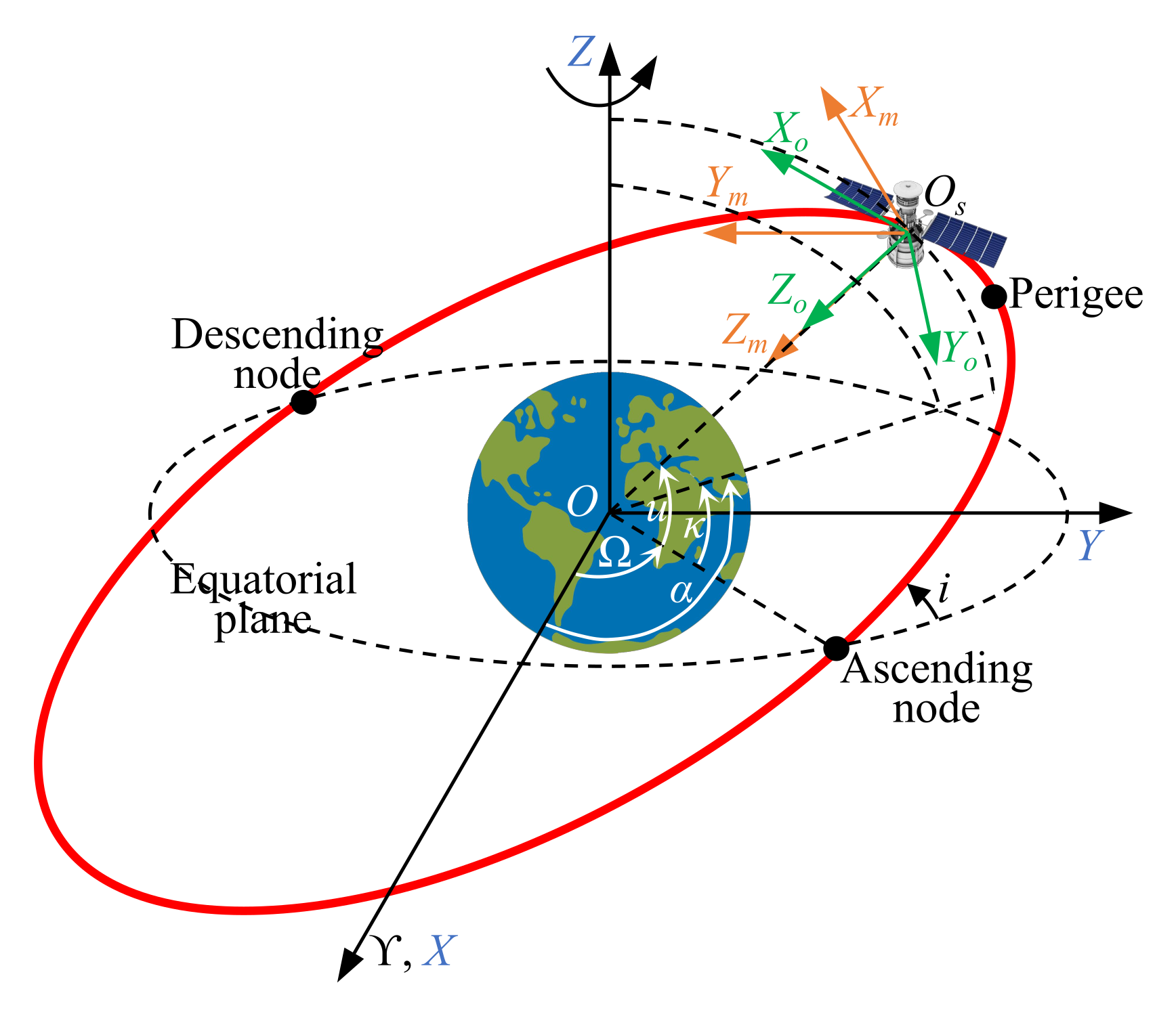
Figure 1. Definition of coordinate systems.
Aerospace 09 00511 g001
Figure 2. Deorbiting principle of the GME propulsion [32,33].
Aerospace 09 00511 g002
Figure 3. Dumbbell model of the debris–spacecraft configuration system.
Aerospace 09 00511 g003
Figure 4. Diagram of GME storage at the fixed axis of orbital frame O s X o Y o Z o : (a) energy storage at Y o -axis, i.e., the debris rotates around the Y o -axis to accumulate linear kinetic energy; (b) energy storage at Z o -axis, namely, the debris rotates around the Z o -axis to accumulate linear kinetic energy.
Aerospace 09 00511 g004
Figure 5. Mechanism establishment of directional energy storage based on dipole model: (a) energy storage at Y o -axis, where m is in X m O s Z m plane, and the argument of ascending node ranges from 90 to 90 in this figure; (b) energy storage at Z o -axis, where m is in X m O s Y m plane. The m always points to east in this figure, so the angular momentum is accumulated in the negative direction of Z o -axis. North (or south) denote the Earth’s geographic north (or south) as well as magnetic north (or south).
Aerospace 09 00511 g005
Figure 6. Dipole model–based Y o -axis result of GME storage in one orbital period by using Y o -axis directional strategy Equation (12) ( m = 10 3 Am 2 ): the result for the other two axes is 0 under dipole model, indicating the realization of the directional energy storage at Y o -axis. This strategy is more suitable for large inclination orbit, but does not have energy storage capacity for LEO with equatorial near-zero inclination.
Aerospace 09 00511 g006
Figure 7. IGRF model–based triaxial results of GME storage in one orbital period by using Y o -axis directional strategy Equation (14) ( m = 10 3 Am 2 ): there are negligible differences between the IGRF and the dipole model–based result at Y o -axis (Figure 6). The other two axes’ result is not zero and bigger than that of Y o -axis in orbit with near-zero inclination. So the strategy cannot be used for LEOs with small inclination.
Aerospace 09 00511 g007
Figure 8. Dipole model–based Z o -axis result of GME storage in one orbital period by using directional Z o -axis strategy Equation (13) ( m = 10 3 Am 2 ): the result for other two axes is 0 under dipole model, indicating the realization of directional energy storage at Z o -axis. This strategy is more suitable for small inclination orbit, and has an energy storage capacity for entire LEOs.
Aerospace 09 00511 g008
Figure 9. The IGRF model–based triaxial results of GME storage in one orbital period by using directional Z o -axis strategy Equation (13) ( m = 10 3 Am 2 ): there are negligible differences between the IGRF model–based and the dipole model-based GME storage at Y o -axis (Figure 8).
Aerospace 09 00511 g009
Figure 10. Energy storage capability of GME propellant approach in one orbital period: accumulate 10 1 to 10 2 Nms for about 100 min under m = 10 3 Am 2 . When i > 49 . 16 , we adopt the strategy Equation (14) for on-orbit energy storage to deorbit debris; otherwise, we use the strategy Equation (13).
Aerospace 09 00511 g010
Figure 11. Schematic of magnetic moment and stator mounted on the spacecraft body for ground systems. The magnetic moment, stator, and spacecraft body are fixed connections, forming part one of the ground systems. The rotor, rotatable part, and rotor are fixed links, forming part two of the ground system. The two parts can rotate relative to each other around the vertical rotation axis.
Aerospace 09 00511 g011
Figure 12. Closed-loop control of ground system.
Aerospace 09 00511 g012
Figure 13. Simulation results: (a) Angular velocity of part two. (b) Angular velocity of spacecraft body. (c) Angular displacement of spacecraft body. (d) Angular acceleration of spacecraft body.
Aerospace 09 00511 g013
Figure 14. Ground experimental system.
Aerospace 09 00511 g014
Figure 15. Attitude changes of spacecraft body in GME harvesting experiment.
Aerospace 09 00511 g015
Figure 16. Linear velocity of debris in disturbance torque calibration experiments.
Aerospace 09 00511 g016
Figure 17. Relationship of disturbance torque and angular velocity of debris.
Aerospace 09 00511 g017
Figure 18. Linear velocity of debris of proof-of-principle experiments.
Aerospace 09 00511 g018
Figure 19. Acceleration changes of debris under different magnetic torque.
Aerospace 09 00511 g019
Figure 20. Attitude change of spacecraft body and magnetic moment.
Aerospace 09 00511 g020
Figure 21. Δ V of debris (exp: experimental value and the: theoretical value).
Aerospace 09 00511 g021
Table 1. Integration time for required Δ V of SD in different circular orbits with different inclinations by GME propellant approach under m = 10 3 Am 2 .
Altitude/km Δ V /(m/s)Required Time/Days
(from 0 to 90 )
Comment
300442.70–1.2310 kg · 10 m
400734.65–2.13
5001016.75–3.09
6001278.84–4.04
70015411.22–5.13
80017913.57–6.20
90020416.16–7.39
100022918.84–9.61
Table 2. Magnetic torque τ g of coils under different DC current.
DC Current/AMagnetic Moment/ Am 2 Geomagnetic Field
Intensity/nT
τ g /Nm
4360020645.85650.0755
654000.1115
1090000.1859
Table 3. Parameters and results of proof-of-principle experiments.
No.Current/A τ g /NmDebris/kg Δ V max / m / s Comment
exp-s140.075525.8
exp-s260.111526.5
exp-s3100.185929.6
exp-d002 (700s)2Disturbance
torque
calibration
Table 4. Δ V of debris at different times.
Time/s0.0755 Nm0.1115 Nm0.1859 Nm
Experimental
Value/(m/s)
Theoretical
Value/(m/s)
Experimental
Value/(m/s)
Theoretical
Value/(m/s)
Experimental
Value/(m/s)
Theoretical
Value/(m/s)
100.2720.2650.3260.3910.6670.653
200.5620.5300.8250.7831.3881.305
300.7980.7951.1911.1741.9921.958
401.0161.0601.5491.5662.4772.611
501.2251.3251.8771.9572.9763.263
601.4001.5902.2722.3493.3783.916
Publisher’s Note: MDPI stays neutral with regard to jurisdictional claims in published maps and institutional affiliations.