Article

Experimental Study on the Effect of Rubbing Mode on Radial Crack Initiation in Labyrinth Seal Fins of Shrouded Turbine Blade

1
College of Energy and Power Engineering, Nanjing University of Aeronautics and Astronautics, Nanjing 210016, China
2
Hunan Aviation Powerplant Research Institute, Aero Engine Corporation of China, Zhuzhou 412002, China
*
Authors to whom correspondence should be addressed.
Aerospace 2022, 9(8), 441; https://doi.org/10.3390/aerospace9080441
Submission received: 11 July 2022 / Revised: 4 August 2022 / Accepted: 8 August 2022 / Published: 12 August 2022
(This article belongs to the Section Aeronautics)

Abstract

:
The labyrinth-honeycomb seals have been widely used in aero-engine. However, radial cracks appear on labyrinth seal fins of shrouded turbine blade in use. To clarify the rubbing mode of radial crack initiation, a high-speed rubbing test bench was designed. The effects of five rubbing modes on crack initiation were studied. Through the test, it is found that cracks would be formed at the junction of the fin tip and side of the labyrinth seal fins under all five modes. When two successive rubbing modes are different, the temperature of the last rubbing can be lower than that of it alone rubbing, and simultaneous radial and axial rubbing can inhibit each other. Radial rubbing mainly affects the initiation of cracks on fin tip, while axial rubbing mainly affects the initiation of cracks on the side. Moreover, the rubbing temperature is mainly affected by radial force.

1. Introduction

Improving efficiency is an important concern in the field of aero-engine. Leakage of airflow can reduce the efficiency of an engine; hence, reducing the leakage has been a focus of aero-engine development in the recent decade [1]. Generally, a sealing system is designed between rotating parts and stationary parts to control the leakage of airflow. One sealing system is called labyrinth seal, which is composed of several labyrinths on rotating parts and bushings on stationary parts. The bushing with abradable material allows the labyrinth fins to rub against it without causing significant damage or wear to the rotating parts while maintaining an effective sealing interface [2]. At present, a commonly used bushing is the honeycomb seal brazed on the surface of stationary parts as the wearable material [3], as shown in Figure 1. Controlling the clearance of sealing structures is the most economical and effective way to reducing air leakage. Usually, the clearance between the labyrinth seal fin and honeycomb is as small as possible [4]. However, the reduction of clearance can increase the risk of labyrinth seal fin and honeycomb rubbing. The transients of the engine starting, stopping, and hot restarting can lead to misalignment of the sealing parts, and there are also mechanical expansion, vibration, and thermal stress during operation. This causes the fins to rub against the honeycomb, leading to wear or crack of the fins [5,6]. In the maintenance of an engine, it is found that the labyrinth seal fins of the shrouded turbine blade have circumferential wear and radial microcracks, that is, the cracks that originate in the contact zone between the fins and honeycomb and extend to the root of the labyrinth seal fin, which is called radial cracks in this paper. The rapid propagation of radial cracks can lead to blade failure, which can endanger the safe operation of the engine.
At present, domestic and foreign researchers have carried out relevant research work on crack initiation and achieved some results. For example, in experimental research, Tim Pychynski et al. [7], Na Zhang et al. [8], Ulrich Rathmann et al. [9], Corentin Delebarre et al. [10], and Maël Thévenot et al. [11] designed their high-speed rubbing test benches to study the rubbing of seal fin and honeycomb. Among them, Pychynski’s and Rathmann’s test samples are non-segmented seal fin and a section of the bushing. Non-segmented labyrinth seal fin refers to one or more integral ring fins on the shaft, such as the fin of the drum and the turbine fin of a disk; Zhang’s test samples consist of a section of fin and a section of honeycomb. Delebarre’s and Thévenot’s test samples are non-segmented fin and non-segmented bushing. During the above test, the three-dimensional force sensor is used to measure the rubbing force, the infrared thermal imager is used to measure the rubbing temperature, and the rubbing process is recorded by a high-speed camera. Through the experiments, it is found that the rubbing force is mainly affected by the incursion rate [7,8] and rubbing speed [7,12]. The rubbing temperature is related to the rubbing speed and incursion rate. Tim Pychynski and Na Zhang believe that the rubbing force and rubbing temperature are mainly affected by the incursion rate, while Soler believes that the effect of the rubbing speed is more obvious [12]. There are strong interactions between rubbing force, rubbing temperature, and wear behavior of the rubbing system, in which thermal effect plays an important role in rubbing behavior [7]. In addition, Hui Ma [13] reviewed the mechanical model, experimental and numerical analysis model of labyrinth seal fin under rubbing conditions.
At present, it is generally believed that the radial crack of the fin is a thermal crack [14,15,16,17,18,19,20], characterized by small cracks on the surface, with roughly equal spacing and the direction perpendicular to the sliding direction [15]. A possible reason for the initiation of thermal crack is the thermal load in the process of high-speed rubbing, and the local overheating of the contact surface can first form thermoelastic instability [16]. The thermal expansion in the local high-temperature region can produce very high compressive stress, which can easily lead to plastic flow. During contact movement and thermal load release, residual tensile stress can be generated on the contact surface, which may lead to the fracture of brittle inclusions on the surface, resulting in cracks [15,16,17,18]. Micro cracks usually occur on the weakened grain boundary, even if there is no crack, overheating may permanently reduce the strength and hardness of the material. If the grain boundary becomes weak or begins to melt due to overheating, even a small tensile strain is enough to cause cracks [17]. The crack location depends on the rubbing coefficient and Peclet number [18]. Tim Pychynsk [19] taking the heating rod fixed at both ends as an example, analyzed that the radial cracks of a non-segmented fin are mainly caused by high tensile stress, and the mechanical load in the rubbing process can be ignored compared with the thermal load. Applying heating cyclic load to the cylinder fixed at both ends, it is found that the stress and strain in the part depend on the initial temperature and final temperature of the sample, and the final rubbing temperature mainly affects the residual tensile stress [20]. With the increase of the radial incursion rate, the wear mechanism of the fin changes from oxidative wear and adhesive wear to layered wear, and then to metal wear [21]. The participation of axial rubbing can lead to higher rubbing force, rubbing temperature, and wear rate. At a higher axial incursion rate, the rubbing layer on the fin is thicker and the crack is more obvious [22].
In summary, under the condition of rubbing, the residual tensile stress of segmented sealing fins is expected to be much lower than that of non-segmented ones [19], and the initiation reason for segmented fin crack is not clear. For the research on the crack initiation of segmented fin, only two modes of radial rubbing, radial and axial simultaneous rubbing are carried out. However, in the work of aero-engine, the rubbing of turbine blade shroud and honeycomb may have five modes: radial rubbing, axial rubbing, first radial and then axial rubbing, first axial and then radial rubbing, and radial and axial simultaneous rubbing. Therefore, it is necessary to study the effect of rubbing mode on the initiation of radial cracks in labyrinth seal fins of a shrouded turbine blade.
In order to clarify the rubbing mode of the initiation of radial cracks in labyrinth seal fins of a shrouded turbine blade, a high-speed rotary rubbing test bench was built in this paper, which can control radial rubbing and axial rubbing independently. The effect of the above five scraping modes on the initiation of the fin crack is studied.

2. Test System and Method

2.1. Test System

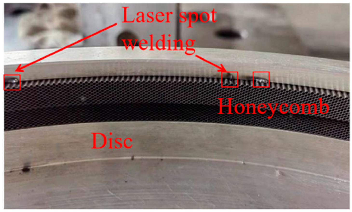
The test is carried out on the high-speed rotary rubbing test bench of Nanjing University of Aeronautics and Astronautics. The test system is shown in Figure 2. To prevent the rotation speed of the disk from reducing during high-speed rubbing, a flywheel with a large mass is installed on the high-speed shaft, which stores energy through the inertia of the flywheel and maintains the rotating speed of the disk during high-speed rubbing. In the actual engine, the honeycomb is installed on the stationary casing, and the turbine blade is installed on the rotating shaft, so the honeycomb is stationary and the labyrinth seal fin is rotating. Since the temperature of the fin cannot be measured in a rotating state, and the thermal load accounts for the main part of the high-speed rubbing process [17], the mechanical load in the rubbing process can be ignored compared with the thermal load [19], therefore the stationary parts and moving parts are exchanged to make the honeycomb rotate in the experiment. The rubbing temperature and rubbing force of the fin are mainly affected by the rubbing speed and incursion rate. In the experiment, rubbing speed can be controlled by controlling the speed of the high-speed motor, and the incursion rate can be controlled by the axial feeding platform and radial feeding platform. Therefore, the rubbing process in the experiment is equivalent to that of the real engine. To prevent the honeycomb from falling off, the honeycomb is installed in the groove of the wheel disc by a combination of laser spot welding and glue bonding, as shown in Figure 3, and the wheel disc is made of 7075 aluminum alloy to ensure its strength. The wheel disc is connected with the high-speed motor through the speed increase box. The high-speed motor is a frequency conversion triple-phase asynchronous motor, the power is 75 kW, and the maximum speed is 3000 r/min. The speed increasing ratio of the speed increasing box is 1:10. By controlling the rotating speed of the wheel disc, the linear speed of the honeycomb is 180 m/s.
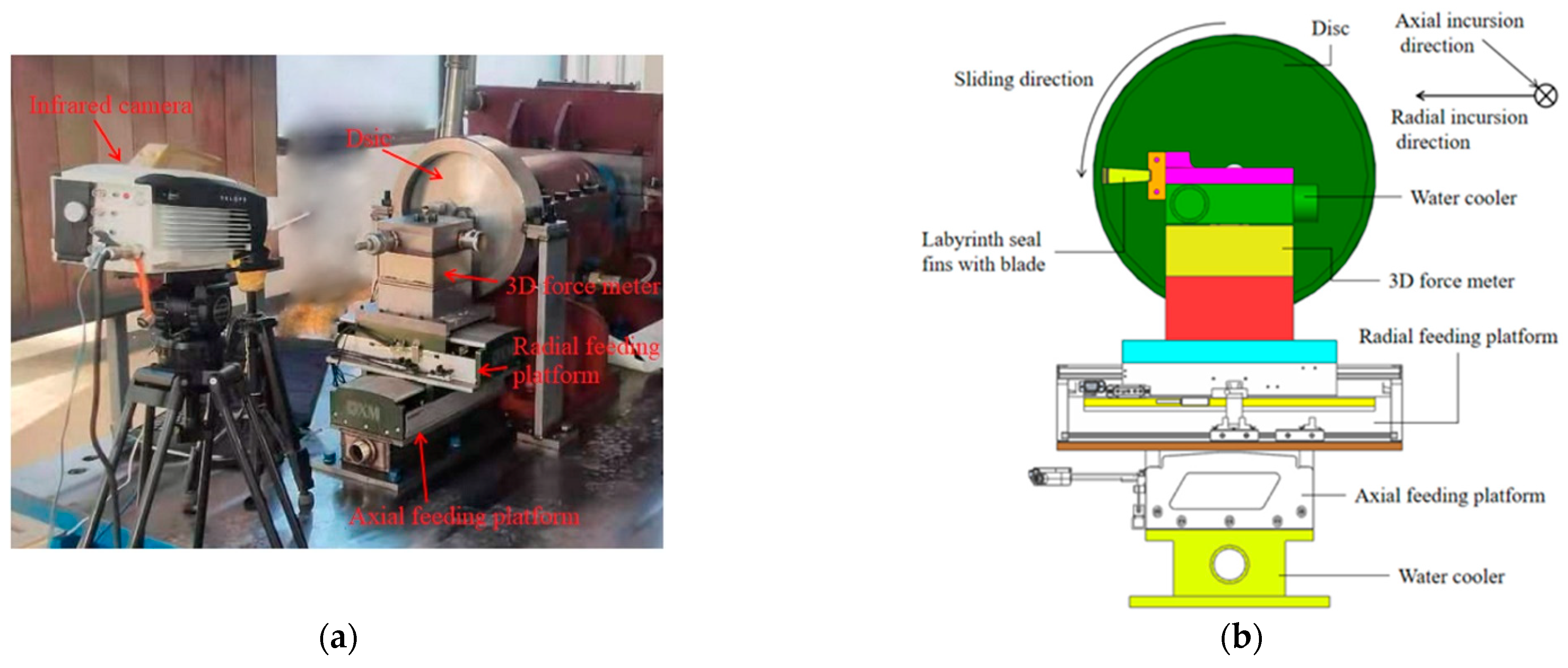
The measurement of temperature and force, and incursion control, are shown in Figure 4. The radial incursion and axial incursion of the labyrinth seal fin are realized by installing the turbine blade on two mutually perpendicular feeding platforms. Both platforms are customized by Nanjing University of Aeronautics and Astronautics. The movement of the platforms is controlled by a linear motor, and the operation accuracy is 2 μm. A three-dimensional force sensor (type T505, Right) is installed under the blade to measure the rubbing force. The measuring range of the sensor is ±1000N and the measurement error is ±2%. Usb8710 (ART technology, Beijing, China) high-speed data acquisition card is used to collect the signal of three-dimensional force, and the acquisition frequency is 100 kHz. The rubbing temperature is measured by infrared thermal imager FAST M200 (Telops, Quebec City, QC, Canada), and the measurement frequency is 600 Hz with 136 × 90 pixels in this paper. The temperature measurement range is 76~612 °C with the 25 mm fixed focus lens, and the range is 76.2913~611.948 °C in fact. Since the working temperature of the platforms and the three-dimensional force sensor is 0~60 °C, to avoid excessive temperature, a water-cooling device is installed under the three-dimensional force sensor and the platform. In this paper, it is defined that the direction along the blade span is radial, the axis direction of the disc is axial, the rotation direction of the disc is circumferential, and the tangent direction of the fin tip surface of the labyrinth seal fin is tangential.

2.2. Test Sample

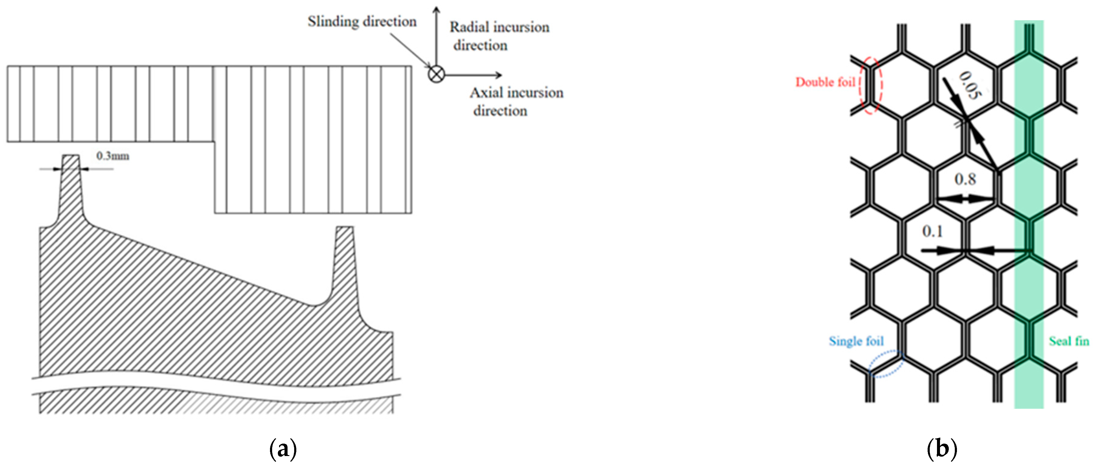
The test samples of the labyrinth seal fin and honeycomb are shown in Figure 5. The test sample is an 8° circular arc step fin, and the height, thickness, and angle of the two fins are the same, and the gap between them and the step honeycomb is 0.5 mm in the initial state. To realize the continuous rubbing in the real engine, four honeycombs are used to form a whole ring and adopt the honeycomb structure commonly used in aero-engines. It can be seen from Figure 5b that the honeycomb is welded by a periodic hexagonal structure (welded at the position of bimetallic foil), and the size of each honeycomb cell is 0.8 mm. The rubbing direction of the fin and honeycomb is parallel to the edge of the bimetallic foil. About 19 turbine blades were used in the test, and all blades were tested only once. Before the test, fluorescent penetration, X-ray, and metallographic examination were carried out, and all blades and fin were free of surface cracks and internal defects.
The materials of the fin and honeycomb are commonly used in aero-engines. The material of the fin is Rene’80, and the material composition is listed in Table 1. The material of the honeycomb is Hastelloy X, and the material composition is listed in Table 2. The mechanical properties of Rene’80 and Hastelloy X are listed in Table 3, and the densities of Rene’80 and Hastelloy X are 8160 kg/m3 and 4430 kg/m3.

2.3. Test Process

Before the test, first move the fin to the position in contact with the honeycomb, adjust the position and angle of the infrared thermal imager to ensure that the temperature at the rubbing position can be photographed, and record the axial slide position and radial slide position as zero. After the fins retreat 5 mm in the radial direction, the high-speed motor is started, and the speed of the motor is adjusted to make the speed of the wheel reach 10,000 r/min. Turn on the infrared thermal imager and the three-dimensional force measurement system to start recording. First, the labyrinth seal fins were moved to the zero point by the radial feeding platform, and the axial feeding platform kept stationary. Then, according to the test conditions, by controlling the incursion rate and displacement of the axial feeding platform and radial feeding platform, the fin can be scraped at the specified incursion rate and incursion depth in the axial and radial directions respectively. After the test, the crack initiation was observed by optical microscope.

2.4. Test Parameters

During the test, the incursion rate and incursion depth were named radial incursion rate (Vr), axial incursion rate (Va), radial incursion depth (Sr), and axial incursion depth (Sa) respectively. They are shown in Figure 6a, and the dotted line indicates the initial position of the seal fin, while the solid line indicates the position at the end of rubbing; mainly research radial rubbing(represented by Ra in paper), axial rubbing(represented by Ax in paper), first radial and then axial rubbing(represented by Ra-Ax in paper), first axial and then radial rubbing(represented by Ax-Ra in paper), and radial and axial simultaneous rubbing(represented by Ra&Ax in paper) on the temperature and cracks initiation of the fin, as shown in Figure 6b. The test conditions of each rubbing mode are listed in Table 4, in which “-” means no slip motion.
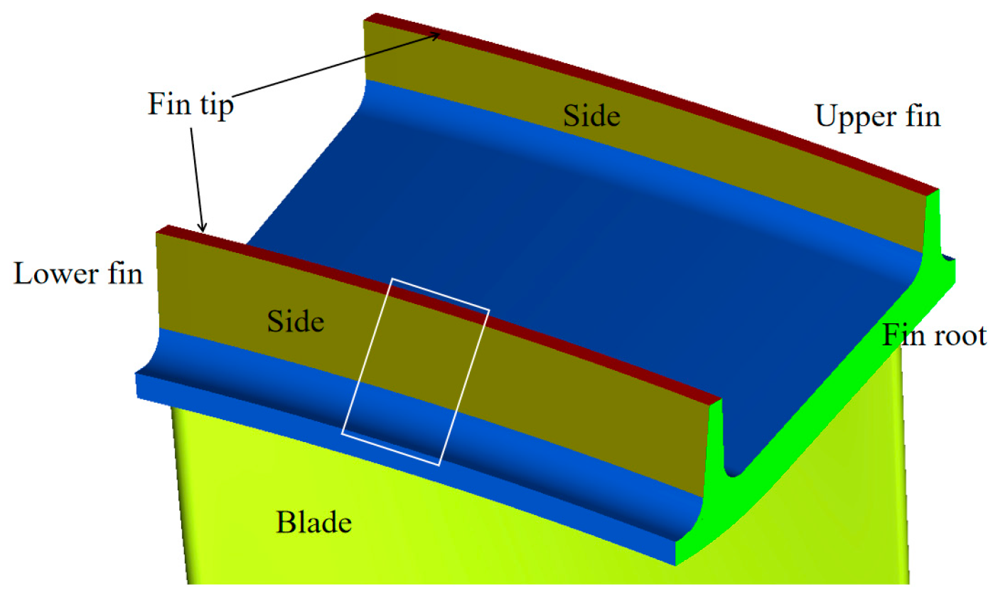
In order to determine the experimental parameters, a blade was used to test the rubbing condition in the Ra-Ax before test. The incursion rate was 20 μm/s, 50 μm/s, 65 μm/s, 80 μm/s, and 100 μm/s when the incursion depth was 0.5 mm, and the incursion depth is 0.1 mm, 0.2 mm, 0.3 mm, and 0.5 mm when incursion rate was 10 μm/s. The situation and the incursion depth of 0.1 mm, 0.2 mm, 0.3 mm are not easy to produce cracks, the incursion rate at 65 μm/s, 80 μm/s, and 100 μm/s is too large, and the severe friction between the fin and the honeycomb makes a layer of filings adhere to the fin tip and both sides of the fin, as shown in Figure 7, which affects the initiation of cracks. Figure 6 is located in the box shown in Figure 7. Therefore, the incursion depth is 0.5 mm and the incursion rate is 50 μm/s. In this paper, the surface corresponding to the honeycomb is called the fin tip, the two adjacent surfaces of the fin tip surface are called the side, and the surfaces at both fin roots of the labyrinth seal fin are called the fin root, as shown in Figure 8.
The rubbing speed, radial/axial incursion rate, and incursion depth in the rubbing process are guaranteed to be constant through the radial feeding platform and axial feeding platform, because the incursion depth is 0.5 mm and the incursion rate is 50 μm/s, the time of single incursion is 10 s. The time of Ra, Ax, Ra&Ax is 10 s, and the time of Ra-Ax and Ax-Ra is the 20 s. In actual experiments, cracks are not necessarily formed in each test, each rubbing mode has been tested times until cracks are formed. Due to welding problems, it cannot be guaranteed that the rubbing force and rubbing temperature are the same, and the maximum difference between temperatures in each mode reaches 60 °C. The number of blades used in each rubbing mode is listed in Table 4.

3. Test Results

3.1. Effect of Rubbing Mode on Rubbing Temperature and Rubbing Force

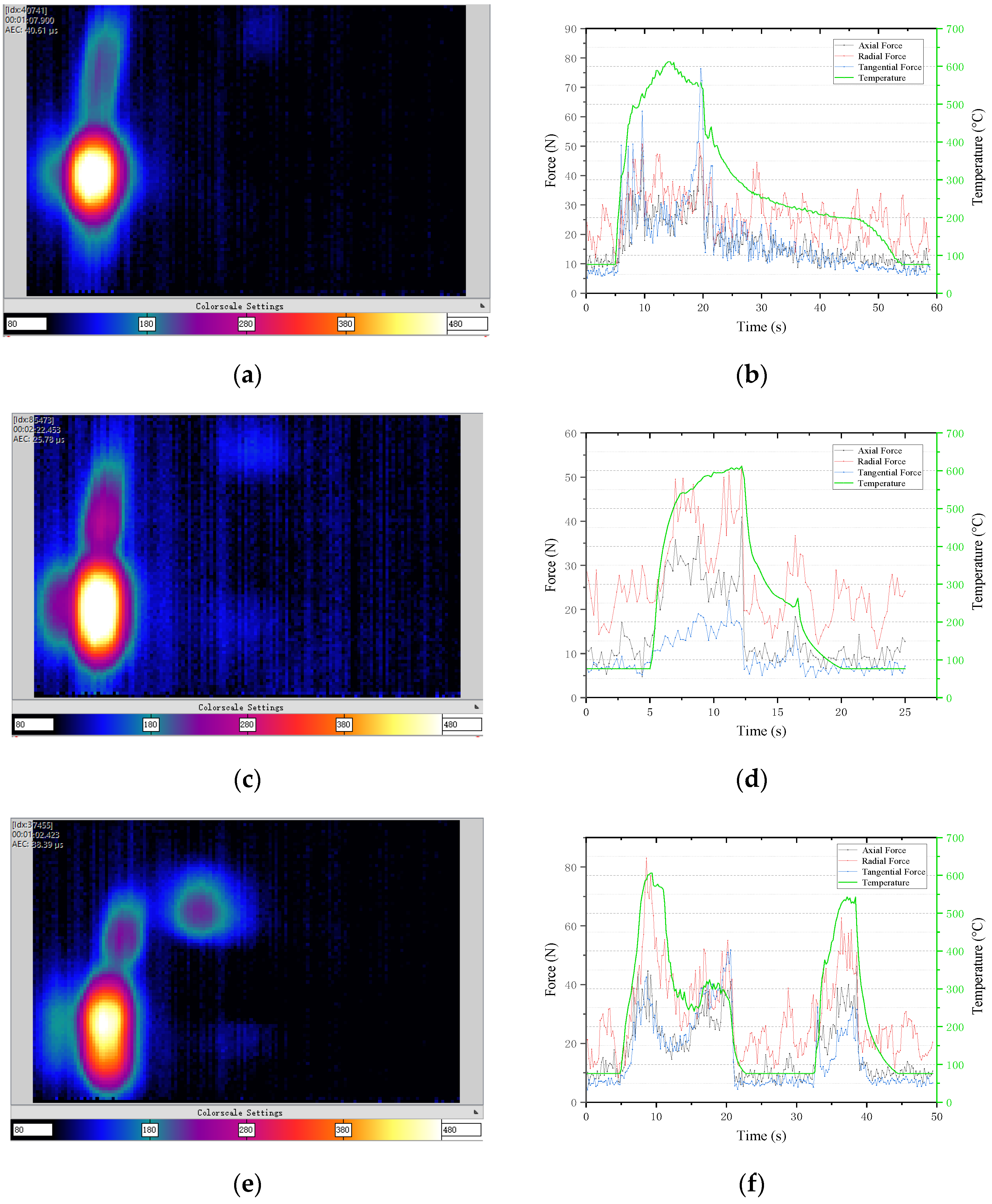
The temperature distributions during rubbing are shown in Figure 9a,c,e,g,i. The measurement location of temperature and force is fin tip, as shown in Figure 8. The coefficient of friction is about 0.64. Rubbing mainly occurs at the upper fin tip of the lower fin, while in Figure 9e,g two fins and the blade crown are rubbed against honeycomb due to the excessive incursion depth (the high-temperature area on the far right in the figure). The rubbing temperature of the middle part of the fin is lower than the upper fin tip because the upper fin tip first contacts the honeycomb and cuts off a part of the honeycomb so that the honeycomb forms a groove with a certain depth; and the gap between the middle part and the honeycomb increases, and the rubbing depth with the honeycomb decreases, so the rubbing temperature is also lower than the upper fin tip.
The changes in temperature and force in the rubbing area are shown in Figure 9b,d,f,h,j. For a single rubbing process, with the rubbing process, the rubbing temperature first rises rapidly, then rises slowly, and then decreases slowly. The reason is that when the honeycomb and the fin are scraped quickly, a quantity of heat is generated and the temperature rises rapidly; as the rubbing progresses, the generation and dissipation of heat in the rubbing area tend to be in dynamic balance, and the rubbing temperature rises slowly. After rubbing, the fins are out of contact with the honeycomb, and the rubbing area is slowly cooled under the airflow. The high frequency change occurs in the stage after rubbing in Figure 9d, because of honeycomb debris rubbing with the fins. At this time, the rubbing have ended, and the temperature have dropped to 300 °C. It will not affect the initiation and propagation of cracks.
Compared with Figure 9b,d, under the same incursion depth and incursion rate, the maximum rubbing temperatures of radial rubbing and axial rubbing both are 611.95 °C. Since a 25 mm fixed-focus lens is used, the temperature measurement range is 76~612 °C. When the actual temperature is greater than 611.95 °C, it will display as 611.95 °C. There are three temperature points of 611.95 °C in radial rubbing and one point in axial rubbing. However, the maximum rubbing temperature of axial rubbing lasts longer than that of radial rubbing. The cooling process of radial rubbing lasts longer and the temperature drops more gently, which can also be seen in Figure 9f,h. In general, the temperature of radial rubbing is more like the “Λ” type, and it begins to drop when it reaches the maximum temperature; while the temperature of axial rubbing is more like the “n” type, which can be maintained for some time after reaching the maximum temperature, and then begin to decrease. Assuming that the rubbing coefficient in the rubbing process is constant, the heat flux in the rubbing process only depends on the rubbing speed and rubbing [15]. Because the rotating speed of the honeycomb in the rubbing process is constant, that is, the rubbing speed is constant, the heat flux only depends on the rubbing force. Radial rubbing is a completely intrusive process, the contact area and radial force between fin and honeycomb increase, and the rubbing temperature increases with the increase; when the incursion reaches a given depth, the contact area, radial force, and temperature reach the maximum; after the rubbing, because the fin has invaded into the honeycomb, the cooling effect of the wind caused by the honeycomb rotation on the rubbing and the grinding area is affected. In the axial rubbing process, the contact area and radial force first increase. After the whole fin tip surface of the labyrinth seal fin contacts the honeycomb, the contact area remains unchanged and the rubbing temperature remains unchanged; After rubbing, there is a gap between the labyrinth seal fin and the honeycomb, and the wind caused by the honeycomb rotation can quickly cool the rubbing area.
Comparing Figure 9f,h, it can be seen that whether it is Ra-Ax or Ax-Ra, the maximum temperature of the previous rubbing is higher than that of the next rubbing, and the maximum temperature of the previous rubbing is similar in both the cases. The maximum temperature of the latter rubbing is similar in both cases regardless of the rubbing mode. The maximum temperature of the previous rubbing is similar to that of the corresponding separate rubbing test. The maximum temperature of radial rubbing is 611.95 °C, and the maximum temperature of radial rubbing in Ra-Ax is 606.06 °C. In axial radial rubbing, the maximum temperature of axial rubbing is 611.95 °C with one point. The maximum temperature of the last rubbing is lower than that of the corresponding separate rubbing test. The maximum temperature of axial rubbing in Ra-Ax is 529.89 °C, and the maximum temperature of radial rubbing in Ax-Ra is 528.82 °C. This result is only applicable when the two rubbing modes are different, when the two rubbing modes are the same, the maximum rubbing temperature increases with the number of rubbing times.
Comparing Figure 9f,h,j, it can be seen that the maximum temperature of simultaneous radial and axial rubbing is lower than that of single radial and single axial rubbing, and the maximum temperature of simultaneous radial and axial rubbing is 593.87 °C. The reason is that the contact is unstable in the contact process, and the contact area is smaller than that of single radial rubbing or single axial rubbing.
A comprehensive comparison of Figure 9b,d,f,h,j shows that the radial force is significantly greater than the axial force, which is the same as the test results in references [13,22]. Comparing the effects of radial force, axial force, and tangential force on temperature, the effect of tangential force on temperature is not obvious, which can be seen in radial rubbing and axial radial rubbing, when the tangential force is maximum, the temperature does not rise significantly. Under the five rubbing modes, the temperature changes obviously with the radial force. It can be seen that the temperature increases with the increase of radial force and decreases with the decrease of radial force. Therefore, the rubbing temperature is mainly affected by radial force.

3.2. Effect of Rubbing Mode on Wear Morphology

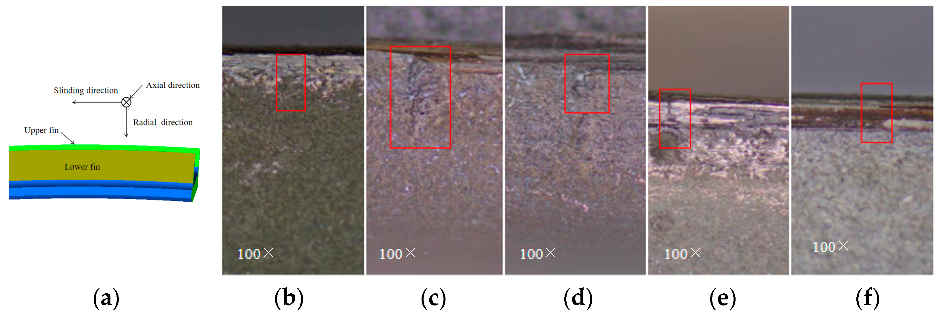
The wear morphology of the fin tip surface of the labyrinth seal fin after rubbing is shown in Figure 10. The rubbing position and direction are shown in Figure 10a. The fin tip surface of the labyrinth seal fin scraped radially has obvious circumferential scratches, and the fin tip surface of the fin scraped axially is relatively smooth without obvious scratches. There are circumferential scratches on the fin tip surface of the fin with Ra-Ax, but weaker than the Ra. A possible reason is that part of the circumferential scratches formed first is removed by axial rubbing. There are obvious circumferential scratches on one side of the fin tip surface of the labyrinth seal fin with axial radial rubbing, and one side is relatively smooth. The reason is that the height of fin tip is inconsistent due to axial scraping. The higher part is scraped radially to form obvious circumferential scratches, while the lower part is not affected, so it is relatively smoother. There are slight circumferential scratches on the surface of the fin rubbed at the same time in the radial and axial directions, but there is no smooth surface, and the surface is mottled and inconsistent in height.

3.3. Effect of Rubbing Mode on Crack Initiation

The crack morphology of the fin tip surface of the labyrinth seal fin obtained by the five rubbing modes is shown in Figure 11. The rubbing position and direction are same as Figure 10a. Cracks are initiated at the junction of the fin tip surface and the side surface. Among them, Ra, Ra-Ax, Ax-Ra, and Ra&Ax at the same time produce multiple parallel cracks, most of which are straight lines, and only one crack is generated by Ax. Moreover, the crack direction is axial, i.e., perpendicular to the sliding direction, which is consistent with the results of the literature [21]. In addition, there are circumferential cracks on the fin tip surface of two Ra and one Ax-Ra, that is, cracks parallel to the sliding direction, which may be due to the excessive temperature in the middle of the fin tip surface. The length of these cracks along the axial direction is different. All cracks do not penetrate the fin, and most of them do not expand radially on the side. Only two cracks expand radially by less than 50 μm. The reason is that only one rubbing is carried out, and the thermal stress is not enough to cause further crack propagation. According to the length of the crack, it can be considered that the crack should expand axially on the fin tip surface under the action of rubbing. At the same time, cracks are extending radially on the side.
The crack morphology on the side of the labyrinth seal fin obtained by the five rubbing modes is shown in Figure 12. The rubbing position and direction are shown in Figure 12a. Radial cracks are generated at the junction of the fin tip surface and the side, in zigzag shape, which is different from the crack morphology on the fin tip surface, and the length of the crack along the radial direction is different. Only the cracks in axial radial rubbing mode propagated axially on the fin tip surface, while the cracks in other modes did not propagate axially. The reason is that only one rubbing was carried out, and the thermal stress is not enough to cause the further propagation of the crack.
The longest crack measurement is selected for each scraping mode, and get the influence of rubbing mode on the length of the fin tip and side cracks, as shown in Figure 13. For the fin tip crack, the length of Ra is 289 μm, 41 μm of Ax, 204 μm of Ra-Ax, 374 μm of Ax-Ra, 317 μm of Ra&Ax. The crack of Ax is shorter than that of other rubbing modes. The length of Ra-Ax is lower than that of Ra. The length of Ra&Ax is greater than that of Ra, and the crack of Ax-Ra is the longest. It is known from the above that the maximum temperature under the five modes is similar, and the influence of rubbing force on crack initiation can be ignored. Comparing the distribution of temperature and force of the five rubbing modes, it can be seen that except for Ra&Ax, the maximum rubbing temperature is similar, and the time required for temperature rise is similar, which is about 5 s. The main difference is the time for maintaining the maximum temperature and the process of temperature decreases, in which the process of temperature decrease can be seen as a linear decrease. The total cooling time of Ra is 34 s, and the decrease rate of temperature with time is 13.63 °C/s. The total cooling time of Ax is 8 s, and the decrease rate of temperature with time is 66.96 °C/s. In Ra-Ax, the radial cooling time is 13.4 s, the decrease rate of temperature with time is 39.54 °C/s, the axial cooling time is 7.4 s, and the decrease rate of temperature with time is 63.05 °C/s. In Ax-Ra, the axial cooling time is 4.45 s, the decrease rate of temperature with time is 98.42 °C/s, the radial cooling time is 24.12 s, and the decrease rate of temperature with time is 18.40 °C/s. The total cooling time of Ra&Ax is 6.4 s, and the decrease rate of temperature with time is 79.47 °C/s. The reason for the short crack length under axial rubbing is that the temperature drop rate is large and the crack could not have enough time to expand. The radial rubbing temperature of Ra-Ax is about 300 °C for 3 s in the decline process. The reason why the length of Ra-Ax is lower than that of radial rubbing is that the continuous temperature of 300 °C in the radial rubbing stage leads to the reduction of thermal stress and cannot maintain the further expansion of cracks. The reason for the longest crack length in Ax-Ra is that a short crack is first produced in axial rubbing, and then it expands rapidly in the process of temperature drop in radial rubbing. The reason why the crack length of axial and radial simultaneous rubbing is small is that the maximum rubbing temperature is low.
For side cracks, the crack length of Ra is 436 μm. The crack length of Ax is 786 μm. The crack length of Ra-Ax is 780 μm. The crack length of Ax-Ra is 659 μm. The crack length of Ra&Ax is 393 μm. It can be seen from Figure 8 that the reason why the crack length of Ax-Ra is lower than that of Ra-Ax is that the final falling temperature in the axial rubbing stage is high, and the reason why the crack of Ra&Ax is the shortest is that the maximum rubbing temperature is low. The reason why the crack of Ax is longer than that of radial rubbing is not clear, and further experimental research is needed.
Based on the above analysis, it can be concluded that radial rubbing mainly affects the initiation of fin tip cracks, axial rubbing mainly affects the initiation of side cracks, and simultaneous axial and radial rubbing could counteract part of the effect. The fin tip cracks and side cracks are formed at the junction of the fin tip surface and the side. The fin tip crack extends along the axial direction and is mainly affected by the falling rate of rubbing temperature, and the side crack extends along the radial direction.

4. Conclusions of Testing

In this paper, the effects of five rubbing modes on the initiation of labyrinth seal fins are studied by experimental method. The conclusions are as follows:
(1)
Radial cracks will be formed on the fin tip and side of the fins under five rubbing modes, and the cracks are formed at the junction of the fin tip and side. The cracks on the fin tip surface of the fins extend in the axial direction, and the crack shape is mostly straight and parallel to each other. The cracks on the side extend in the radial direction, and the cracks are in the shape of crack-like.
(2)
Under the five rubbing modes, the value of radial force is significantly greater than that of axial force. The effect of tangential force on temperature is not obvious. When the tangential force increases rapidly, the rubbing temperature does not increase significantly. The temperature is mainly affected by radial force. The rubbing temperature increases with the increase of radial force and decreases with the decrease of radial force.
(3)
The maximum rubbing temperatures of radial rubbing and axial rubbing are equal, which is 611.95 °C. When the two successive rubbing modes are different, temperature of the latter can be lower than that of the corresponding individual rubbing model. The maximum temperature of axial rubbing in Ra-Ax is 529.89 °C, and the maximum temperature of radial rubbing in Ax-Ra is 528.82 °C. The simultaneous radial and axial rubbing and grinding will inhibit each other, and the rubbing temperature is 593.87 °C.
(4)
There are obvious circumferential scratches on the fin tip surface of the fin scraped radially, and the fin tip surface of the fin rubbed axially is relatively smooth. Radial rubbing mainly affects the initiation of fin tip cracks, and axial rubbing mainly affects the initiation of side cracks. The crack in fin tip is mainly affected by the decreasing rate of rubbing temperature.

Author Contributions

Conceptualization, W.Z., Y.L. and B.Z.; methodology, Y.Y.; software, Z.M.; validation, Y.Y., Z.M. and J.C.; formal analysis, Y.Y.; investigation, Y.Y. and J.C.; resources, Z.M.; data curation, Y.Y. and J.C.; writing—original draft preparation, Y.Y.; writing—review and editing, Y.Y.; visualization, J.C.; supervision, W.Z. and W.Y.; project administration, W.Y.; funding acquisition, W.Z., Y.L. and B.Z. All authors have read and agreed to the published version of the manuscript.

Funding

This research received no external funding.

Data Availability Statement

Not applicable.

Conflicts of Interest

The funders had no role in the design of the study; in the collection, analyses, or interpretation of data; in the writing of the manuscript; or in the decision to publish the results.

References

  1. DeMasi-Marcin, J.T.; Gupta, D.K. Protective coatings in the gas turbine engine. Surf. Coat. Technol. 1994, 68–69, 1–9. [Google Scholar] [CrossRef]
  2. Chupp, R.E.; Hendricks, R.C.; Lattime, S.B.; Steinetz, B.M. Sealing in Turbomachinery. J. Propuls. Power 2006, 22, 313–349. [Google Scholar] [CrossRef]
  3. Draskovich, B.S.; Frani, N.E.; Joseph, S.S.; Narasimhan, D. Abrasive Tip/Abradable Shroud System and Method For gas Turbine Compressor Clearance Control. U.S. Patent 5,704,759, 6 January 1998. [Google Scholar]
  4. Aslan-zada, F.E.; Mammadov, V.A.; Dohnal, F. Brush seals and labyrinth seals in gas turbine applications. Proc. Inst. Mech. Eng. Part A J. Power Energy 2013, 227, 216–230. [Google Scholar] [CrossRef]
  5. Dai, X.; Yan, X. Effects of Labyrinth Fin Wear on Aerodynamic Performance of Turbine Stages: Part II—Mushrooming Damages. In Proceedings of the ASME Turbo Expo 2019: Turbomachinery Technical Conference and Exposition, Phoenix, AZ, USA, 17–21 June 2019. [Google Scholar]
  6. Delebarre, C.; Wagner, V.; Paris, J.Y.; Dessein, G.; Denape, J.; Gurt-Santanach, J. An experimental study of the high speed interaction between a labyrinth seal and an abradable coating in a turbo-engine application. Wear 2014, 316, 109–118. [Google Scholar] [CrossRef]
  7. Pychynski, T.; Höfler, C.; Bauer, H.-J. Experimental Study on the Friction Contact between a Labyrinth Seal Fin and a Honeycomb Stator. J. Eng. Gas Turbines Power 2015, 138, 062501. [Google Scholar] [CrossRef]
  8. Zhang, N.; Xuan, H.-J.; Guo, X.-J.; Guan, C.-P.; Hong, W.-R. Investigation of high-speed rubbing behavior of labyrinth-honeycomb seal for turbine engine application. J. Zhejiang Univ.-Sci. A 2016, 17, 947–960. [Google Scholar] [CrossRef]
  9. Rathmann, U.; Olmes, S.; Simeon, A. Sealing Technology: Rub Test Rig for Abrasive/Abradable Systems. In Proceedings of the ASME Turbo Expo 2007: Power for Land, Sea, and Air, Montreal, QC, Canada, 14–17 May 2007; pp. 223–228. [Google Scholar]
  10. Delebarre, C.; Wagner, V.; Paris, J.Y.; Dessein, G.; Denape, J.; Gurt-Santanach, J. Tribological characterization of a labyrinth-abradable interaction in a turbo engine application. Wear 2017, 370–371, 29–38. [Google Scholar] [CrossRef]
  11. Thévenot, M.; Wagner, V.; Paris, J.Y.; Dessein, G.; Denape, J.; Harzallah, M.; Brunet, A.; Chantrait, T. Thermomechanical phenomena and wear flow mechanisms during high speed contact of abradable materials. Wear 2019, 426–427, 1102–1109. [Google Scholar] [CrossRef]
  12. Soler, D.; Saez De Buruaga, M.; Arrazola, P.J. Experimental investigation of contact forces and temperatures in rubbing interactions of honeycomb interstate seals. IOP Conf. Ser. Mater. Sci. Eng. 2021, 1193, 012070. [Google Scholar] [CrossRef]
  13. Ma, H.; Yin, F.; Guo, Y.; Tai, X.; Wen, B. A review on dynamic characteristics of blade–casing rubbing. Nonlinear Dyn. 2016, 84, 437–472. [Google Scholar] [CrossRef]
  14. Bogdanovich, P.N.; Tkachuk, D.V. Thermal and thermomechanical phenomena in sliding contact. J. Frict. Wear 2009, 30, 153–163. [Google Scholar] [CrossRef]
  15. Kennedy, F.E. Thermal and thermomechanical effects in dry sliding. Wear 1984, 100, 453–476. [Google Scholar] [CrossRef]
  16. Kennedy, F.E.; Karpe, S.A. Thermocracking of a mechanical face seal. Wear 1982, 79, 21–36. [Google Scholar] [CrossRef]
  17. Rossmann, A. Die Sicherheit von Turbo-Flugtriebwerken, Band 2; Turbo Consult: Karlsfeld, Germany, 2000. [Google Scholar]
  18. Kim, S.-W.; Segu, D.Z.; Kim, S.-S. The Thermo-mechanical Cracking Analysis of Break System. Procedia Eng. 2013, 68, 586–592. [Google Scholar] [CrossRef]
  19. Pychynski, T.; Dullenkopf, K.; Bauer, H.-J. Theoretical Study on the Origin of Radial Cracks in Labyrinth Seal Fins due to Rubbing. In Proceedings of the ASME Turbo Expo 2013: Turbine Technical Conference and Exposition, San Antonio, TX, USA, 3–7 June 2013. [Google Scholar]
  20. Hühn, L.; Rieger, F.C.; Bleier, F.; Schwitzke, C.; Bauer, H.-J.; Behnisch, T. Extensive Investigations on Radial Crack Formation in Labyrinth Seals of Aircraft Engines. In Proceedings of the Deutscher Luft- und Raumfahrtkongress, Friedrichshafen, Germany, 4–6 September 2018; p. 8 S. [Google Scholar]
  21. Lu, B.; Ma, X.; Wu, C.; Xuan, H.; Hong, W. The Wear of Seal Fins during High-Speed Rub between Labyrinth Seal Fins and Honeycomb Stators at Different Incursion Rates. Materials 2021, 14, 979. [Google Scholar] [CrossRef] [PubMed]
  22. Lu, B.; Xuan, H.; Ma, X.; Han, F.; Hong, W.; Zhi, S. The Influence of the Axial Rub Added in the Radial Rub on the Wear of the Seal Fins during the High Speed Rub of Labyrinth-Honeycomb Seal. Materials 2021, 14, 1997. [Google Scholar] [CrossRef] [PubMed]
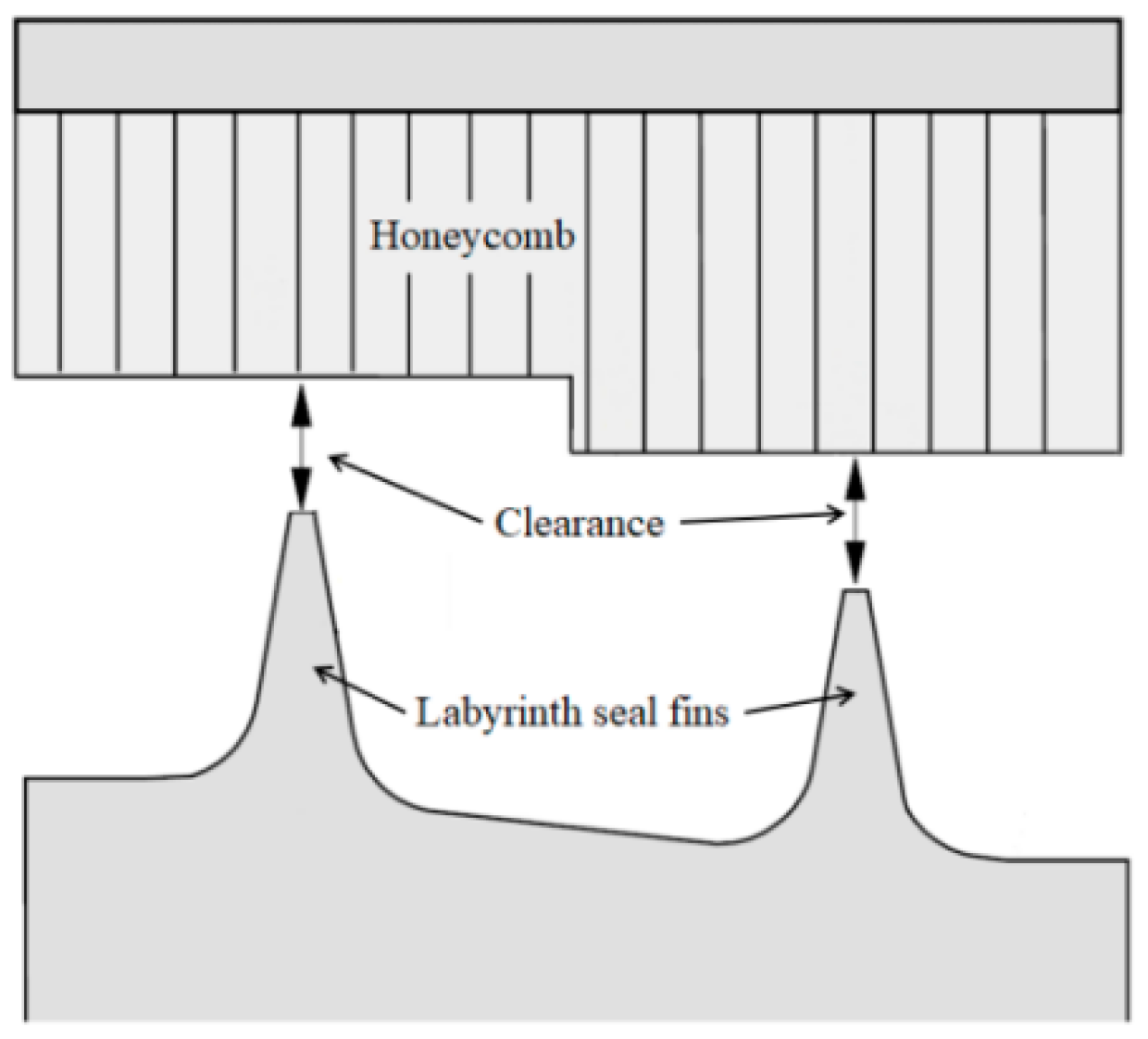
Figure 1. Labyrinth honeycomb sealing system.
Aerospace 09 00441 g001
Figure 2. High-speed rotary rubbing test system.
Aerospace 09 00441 g002
Figure 3. Installation of honeycomb.
Aerospace 09 00441 g003
Figure 4. Incursion control and test measurement. (a) Measurement of temperature and force. (b) Schematic diagram of incursion control.
Aerospace 09 00441 g004
Figure 5. Dimensions of the test sample. (a) Test sample of the labyrinth seal fin. (b) Test samples of honeycomb.
Aerospace 09 00441 g005
Figure 6. Schematic diagram of rubbing parameters. (a) Schematic diagram of Vr, Va, Sr, and Sa. (b) Schematic diagram of rubbing models.
Aerospace 09 00441 g006
Figure 7. Wear of labyrinth seal fin under high incursion rate.
Aerospace 09 00441 g007
Figure 8. Definition of each face of the labyrinth seal fin.
Aerospace 09 00441 g008
Figure 9. Temperature and force in the rubbing process. (a) Temperature of ra. (b) Temperature and force in ra. (c) Temperature of ax. (d) Temperature and force in ax. (e) Temperature of ra-ax. (f) Temperature and force in ra-ax. (g) Temperature of ax-ra. (h) Temperature and force in ax-ra. (i) Temperature of ra&ax. (j) Temperature and force in ra&ax.
Aerospace 09 00441 g009aAerospace 09 00441 g009b
Figure 10. Wear morphology of labyrinth seal fin after rubbing. (a) Schematic diagram of fin tip shooting position and direction. (b) ra (c) ax (d) ra-ax (e) ax-ra (f) ra&ax.
Aerospace 09 00441 g010
Figure 11. Cracks on the fin tip.
Aerospace 09 00441 g011
Figure 12. Cracks on the side. (a) Schematic diagram of side shooting position and direction. (b) ra (c) ax (d) ra-ax (e) ax-ra (f) ra&ax.
Aerospace 09 00441 g012
Figure 13. Length of cracks on the fin tip and side.
Aerospace 09 00441 g013
Table 1. Composition of Rene’80 (wt.%).
CompositionCCrNiCoWMoAlTiFe
Content/%0.1613.8balance94.03.83.14.80.32
Table 2. Composition of Hastelloy X (wt.%).
CompositionNiCrFeMoCoWCMnSiB
Content/%balance221891.50.60.10.980.950.007
Table 3. The mechanical properties of Rene’80 and Hastelloy X.
Rene’80Hastelloy X
E/GPaα/10−6·°C−1σb/MPaσp0.2/MPaE/GPaα/10−6·°C−1σb/MPaσp0.2/MPaT/°C
199.012.561090815187.612.5809361200
175.217.16985630160.314.8531227600
171.018.7975660156.615.2496225650
168.818.421000610154.015.5446223700
Table 4. Test conditions for the influence of different rubbing modes on crack initiation.
Rubbing ModeSr (mm)Vr (μm/s)Sa (mm)Va (μm/s)Number of Blades
Ra0.550--5
Ai--0.5504
Ra-Ai0.5500.5505
Ai-Ra0.5500.5503
Ra&Ai0.5500.5502
Publisher’s Note: MDPI stays neutral with regard to jurisdictional claims in published maps and institutional affiliations.