Article

Capture Dynamics and Control of a Flexible Net for Space Debris Removal

1
School of Electronical and Information Engineering, Beijing JiaoTong University, Beijing 100044, China
2
TsingAero Armament Technology Co., Ltd., Beijing 102210, China
3
School of Aerospace Engineering, Tsinghua University, Beijing 100084, China
*
Author to whom correspondence should be addressed.
Aerospace 2022, 9(6), 299; https://doi.org/10.3390/aerospace9060299
Submission received: 3 April 2022 / Revised: 30 May 2022 / Accepted: 30 May 2022 / Published: 1 June 2022
(This article belongs to the Special Issue Recent Advances in Spacecraft Dynamics and Control)

Abstract

:
Space debris severely threatens the safety of spacecraft in near-earth orbit. Dragging space debris into the atmosphere to burn is an effective way to remove it. In this paper, the authors focus on capturing irregular and rotating debris via a flexible net. The net capture dynamics, including the constitutive dynamics of the flexible net and the nonlinear contact dynamics with the debris, are established to simulate the movements of the flexible net. The debris dynamics, comprising translational and rotational dynamics, are constructed to simulate its motions throughout the whole process. In addition, an active control scheme is applied to designing the controllers of the flexible net. The presented method can be used to simulate the capture and post-capture process of irregular and rotating debris. Moreover, compared with the previous space debris capture mechanism, the presented flexible net can be opened or closed repeatedly; thus, the proposed flexible net has more potential to capture many pieces of debris in one mission. Numerical simulations show that the flexible net has an excellent capture capability with the presented control scheme. The flexible net can capture the debris rotating with an angular velocity of 6.28 rad/s. Moreover, the debris can be fully enveloped and further dragged away along the expected trajectory. The critical indicator results show that the wrapping of the debris is stable; thus, this method is feasible for future missions.

1. Introduction

Space debris has severely threatened the safety of spacecraft in near-earth orbit in recent years. Meanwhile, more and more new pieces of space debris are being produced by hyper-velocity collisions between the existing ones [1,2]. All these pieces of space debris obstruct the ability of humankind to explore space. Significantly, pieces of debris smaller than 20 cm in size are difficult to observe from remote ground bases [3]; thus, they potentially threaten the safety of spacecraft. The active debris capture (ADC) mission, which aims to capture target debris and drag it into the atmosphere to burn, therefore appears promising [4,5,6,7].
Capture strategies can be simply characterized as stiff connection capturing and flexible connection capturing [1]. In terms of stiff connection mechanisms, tentacles [1,8], single robotic arms [1,9,10,11], and multiple arms have been widely researched [1,12]. The stiffness of composites, the ease with which they can be tested on the ground, and higher technology readiness level are their three obvious strengths compared to flexible connection capturing [1]. However, high precision rendezvous and docking are necessary for these mechanisms to function. Thus, it is much harder to capture space debris using a stiff connection strategy [13,14]. Due to the hardness of the material, stiff connection mechanisms are more likely to be destroyed during capture. As for flexible connection mechanisms, harpoons [15,16], tether grippers [17,18], and space nets [1,19] are commonly proposed. Flexible mechanisms allow for a long distance between the mothership and non-cooperative targets, making highly precise docking unnecessary. These mechanisms also have a larger space extension range, which can be used to capture targets with huge dimensions and capture multiple targets in one task. Compared to rigid mechanisms, the material used for these capturing methods is more flexible and thus more adaptive for debris with complicated geometries. The validity of these mechanisms can also be tested on the ground [20,21]. Therefore, flexible connection capturing has acquired more and more attention in recent years. In this study, a flexible net, which consists of a flexible net and several actuators connected to its corners, is proposed to execute the ADC mission.
The contact process in a weak gravitational environment is highly nonlinear. As space debris always moves with a rotational velocity and a translational velocity, it can distort the shape of the flexible net and thus escape from it. The shape of the debris is irregular; the deformation of the net can become large after coming into contact with the debris; and the impact of the rotating debris can be destructive to the flexible net, for example, high-speed rotating debris could tear the net. Meanwhile, the dynamics of the flexible net after contact are vital to the success of the mission. After capturing the target debris, the flexible net needs to drag it into the atmosphere to burn. Thus, the question of how to control the flexible net for use in further operations is worth considering.
Table 1 shows the comparisons of the proposed method with the previous methods. Shan et al. [21] investigated the contact dynamics of the tumbling space debris and gave the threshold of the tumbling rate for the mechanical net closing mechanism. The net dynamics and the dynamics of the debris are established to simulate the movement of the whole capture system. However, the post-capture or control movement of the net is not considered. Moreover, with the net closing mechanism in [21], the debris cannot be further removed because there are no actuators in the capturing system [21]. In our study, a flexible net is proposed for a robot with four actuators connected to its corners. Besides modeling the net dynamics, we also establish a model of the dynamics of the debris to simulate its movement, including the translational and rotational dynamics. With the designed active control scheme, the debris can be fully enveloped and further dragged away along the desired trajectory. Zhao et al. [22] proposed the use of a tethered space net robot to capture a fixed cylinder-shaped piece of debris. Contact dynamics models are established to analyze the contact process and a slide control scheme is presented to close the net. However, the dynamics of the debris are not taken into account. Zhao et al. [23,24] studied the capture dynamics and control of tethered space net robots for capturing space debris in an unideal capture case, which means that the collision between the net and the debris is not a central collision. Additionally, the integral adaptive super-twisting sliding mode control is used to close the net. However, in that study, the target debris is fixed, although the net comes into contact with the debris [22]. Moreover, no dynamics model of the debris is established. In actual fact, in the microgravity environment, the debris can rotate or move if the net comes into contact with the debris. In our study, a dynamics model of the debris is established, considering both the translational and rotational dynamics. Benvenuto et al. [25] proposed a net capture system comprising a spacecraft and a flexible net. The flexible net is connected to the spacecraft by a long rope. The net is closed by mechanical mechanisms. The spacecraft can drag the flexible net to remove captured debris. The whole capture process is simulated using a multi-body dynamics simulation tool. However, if the net is closed, it cannot be opened again. In other words, only a few pieces of debris can be removed at a time. In our study, the capturing system is different to the one described in [25]. The capture system used in this study is a flexible net with four actuators connected to its corners. There is no spacecraft in our capture system. The net can be closed or opened by controlling the actuators. That is to say, the flexible net can remove many pieces of debris by controlling the net repeatedly. Moreover, Si et al. [26] simulated the net capture process of space debris, and the self-collision of the tether net was considered in their study. Comparing results show that the capture process with the self-collision differs from the one without considering self-collision. In fact, self-collision should be considered to direct the future mission. The self-collisions of the net will be considered in our future studies. Endo et al. [27] investigated the factors affecting the robustness of the capture process, such as the distance from the net to the debris and the deployed size of the net at the timing of collision with the debris. The results imply that the net should be ejected with an appropriate deployment rate, according to the debris size and distance to debris. In our study, we control the actuators to drag the net to ensure the capture robustness. Botta et al. [28] proposed a dynamic model of a tether-actuated closing mechanism for net-based capture of space debris. The algorithm was integrated into Vortex Studio software to simulate the net capture process. In our study, the capturing system is also different from the one described in [28]. Shan et al. [29] compared the mass-spring method and the ANCF method for net flexibility modeling. The influence on the net behavior by the flexibility modeling is analyzed via simulations for the first time. Results show that the flexibility modeling has little influence on the net dynamics in simulation. Hou et al. [30] used the discrete elastic rods method and energy-conserving integration method to establish the dynamics model of the net. The deployment process of the net was studied using this method. The study shows that the method of discrete elastic rods is more suitable for modeling the extremely flexible threads than the slender beam elements with C1 continuity. Si et al. [31] presented a split closing mechanism that allows the tether-net to close successfully, whether or not it starts to work before or after the net makes contact with the target. A scenario where the net captures a fixed spherical target is simulated to demonstrate the split closing mechanism.
Some dynamical modeling methods for flexible nets described in prior research were reviewed for reference. Shan et al. [32] used the mass-spring parallel method and the absolute nodal coordinate formulation method to construct a nonlinear constitutive model of a flexible net and, as explored in the expansion process, the results show that the computational amount dealt with in the absolute nodal coordinate formulation method is much larger than that in the mass-spring parallel method, although the absolute nodal coordinate formulation method can repeat the evolutionary behaviors of the flexible net more naturally. Gärdsback et al. [33] studied a robust control method for a successful spin deployment and proposed the use of an analytical three-degree-of-freedom model and a fully three-dimensional finite element model to analyze the deployment of the space flexible net. The results show that space flexible nets are suitable for use in very large structures. Botta et al. [14] utilized a lumped-parameter approach for simulating the dynamics of a flexible net, and the capability of the net was demonstrated by multiple numerical experiments. Fan et al. [34] derived the motion equations of a space net for both symmetrical and asymmetrical configurations and presented a modified adaptive super twisting sliding-mode control scheme to control a flexible net. There are many closing mechanisms that can be used in tether-net capturing [35]. Many modeling methods have been developed to study net capturing dynamics in previous studies. In this paper, we further study the effect of the rotation of debris on the net dynamics and present an active control scheme for controlling debris.
The rest of this paper is organized as follows. Section 2 models the dynamics of the capture system, Section 3 presents the control scheme for the flexible net, Section 4 studies the capture simulations and analyzes the results, and Section 5 summarizes the contributions of this work.

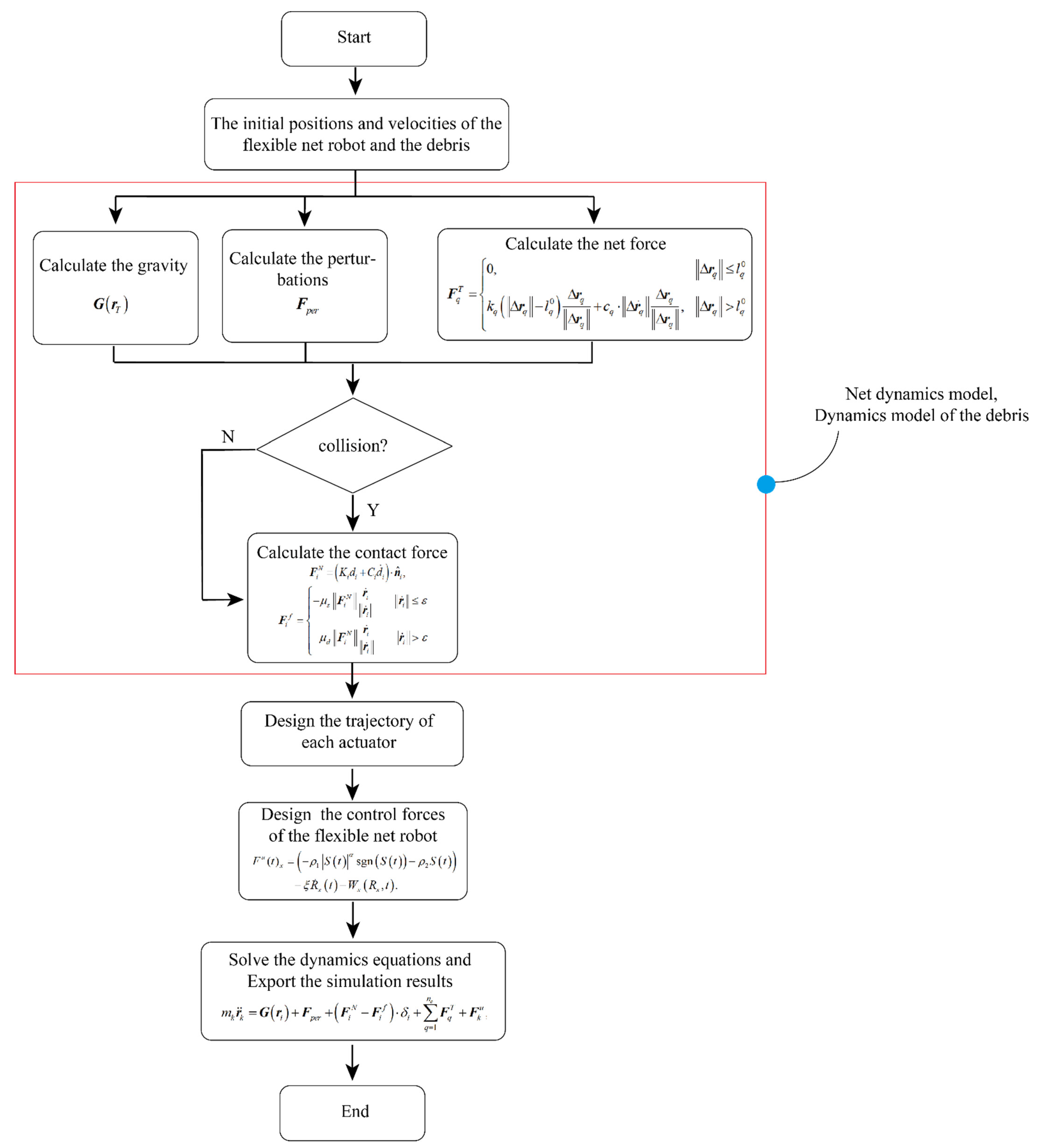
2. Dynamics of the Capture System

The net capture dynamics, including the constitutive dynamics of the flexible net and its nonlinear contact dynamics with the debris, are established for simulating the movement of the flexible net. The debris dynamics, comprising the translational and rotational dynamics, are constructed to simulate its motions during the capture and post-capture processes.

2.1. Constitutive Model of the Flexible Net

The constitutive model of the flexible net is constructed via the Kelvin–Voigt method [13,14,19,30], because less time is needed for calculating the movements and velocities and this model is sufficiently accurate for simulating a large-scale flexible net. Specifically, each net thread can be discretized by combining many mass points and spring-damping parallel connections. The mass of the flexible net mostly concentrates on the mass points. The net dynamics are established by obtaining a dynamics model of each mass point. Each actuator is attached to a corner and treated as the net node when establishing the dynamics model. Referring to the Kelvin–Voigt method, the constitutive model of the tension force F q T of thread q in the flexible net is
F q T = { 0 , Δ r q l q 0 k q ( Δ r q l q 0 ) Δ r q Δ r q + c q Δ r ˙ q Δ r q Δ r q , Δ r q > l q 0 ,
in which k q = E A / l q 0 is the stiffness of the net thread q; E is the Young’s modulus, which can be altered according to the net material, is the cross-sectional area of the thread; and l q 0 is the initial length of the thread q. c q = 2 ζ l q 0 ρ s π ( d / 2 ) 2 k q is the damping coefficient of the thread q, ρ s is the density of the thread q, ζ is the damping ratio, Δ r q is the relative displacement of the two adjacent nodes of segment q, Δ r ˙ q is the relative velocity, and d is the diameter of the thread.
When the flexible net flies through space, microgravity and space perturbations will affect its motion. If the flexible net comes into contact with the debris, the contact forces, including the normal supporting force and tangential friction, will affect the flexible net. If no thrust is generated in the actuator, the dynamics equations of the actuators will be the same as the net nodes. The dynamics equations of the flexible net system are expressed as,
m i r ¨ i = G ( r i ) + F p e r + ( F i N F i f ) δ i + q = 1 n e F q T ,
in which i = 1 , 2 , 3 n ; n is the total number of the net nodes and the actuators; m i is the mass of the net nodes or the actuators; r i , r ˙ i and r ¨ i are the position, velocity, and acceleration of mass point i, and G ( r i ) is the microgravity from Earth; and F p e r is the space perturbations. The term δ i is the collision identification function: if a collision happens, then δ i = 1 ; otherwise, δ i = 0 . F i N is the normal contact force from the debris and F i f is the tangential friction. Finally, n e is the total number of adjacent threads of mass point i.

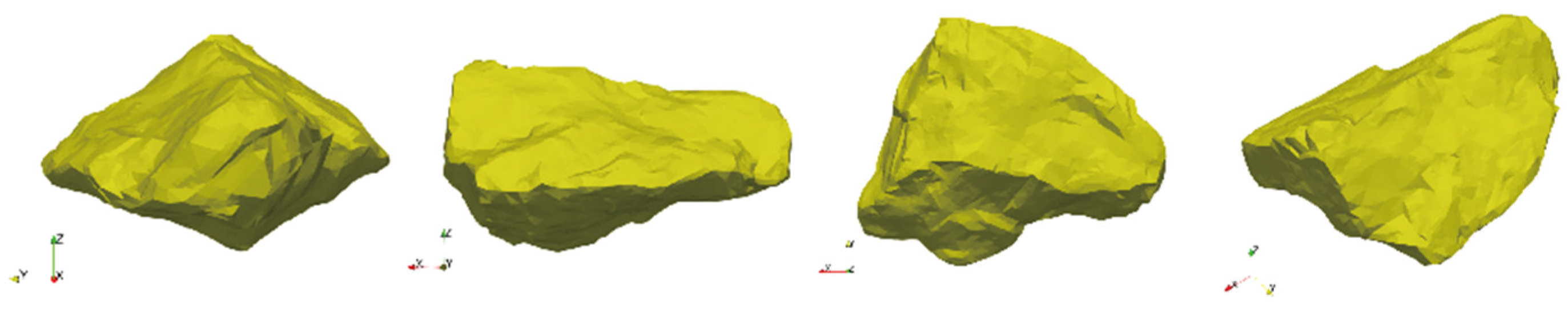
2.2. Dynamics Model of the Debris

In the capture mission, the forces exerted on the non-cooperative debris include microgravity, perturbative forces, and contact forces, which comprise the normal reaction force and tangential friction from the flexible net. Contact forces also contribute to the rotational dynamics of the debris. Thus, the translational and rotational dynamics of the debris can be expressed as
{ m T r ¨ T = F p e r + G ( r T ) + i = 1 n s [ ( F i N F i f ) η i ] I ω ˙ T + ω T × I ω = i = 1 n s [ ( M i N + M i f ) η i ]
where r T ,   r ¨ T denotes the position and acceleration of the mass center of the target debris, respectively. m T is the mass of the debris; F p e r is the space perturbations exerted on the debris. G ( r T ) is the Earth’s gravity; N i is the normal contact force from the net node p in the flexible net, M i N is the normal contact torque; F i f is the friction force from the flexible net; and the M i f is frictional torque. n s denotes the total number of the net nodes in the flexible net robot. The term η i is the collision identification function: if a collision occurs between the net node and the debris, then η i = 1 , otherwise, η i = 0 . I denotes the inertia matrix of the debris. ω ,   ω ˙ T are the angular velocity and the angular acceleration of the debris.

2.3. Contact Dynamics between the Debris and the FNR

If collisions occur between the flexible net and the debris, the normal contact force and tangential friction will affect the transitional and rotational motions of the flexible net and the debris. Contact dynamics are an important part in the simulation of a flexible net capture system. A soft-sphere discrete element method [35,36,37] is generally used for modeling the collision process of two objects. According to this method, the normal contact force of the net node i is
F i N = ( K i d i + C i d ˙ i ) n ^ i ,
K i = m i ( v max 0.01 κ i ) 2 ,
C i = 2 ln ε n K i m i π 2 + ( ln ε n ) 2 ,
in which d i is the permeate depth of two collision objects and is computed at each simulation step; n ^ i is the normal impact vector at the point of collision of two objects and can be calculated referring to [37,38,39]. v max is the maximum velocity during the impact, κ i is the contact radius of the net thread, which is set as the half of the diameter of the net thread, and ε n is the restitution parameter.
After computing the normal contact force, the torque formed by the normal contact force exerted on the debris can be expressed as:
M i N = F i N × ( r i r T )
The friction force also influences the movement and attitude variations in the debris. A simplified Coulomb friction model is used to compute the friction force:
F i f = { μ s F i N r ˙ i r ˙ i r ˙ i ε μ d F i N r ˙ i r ˙ i r ˙ i > ε
where μ s is the static friction coefficient, μ d is the dynamic friction coefficient, and ε is a small static-slide transition value.
After computing the friction, the frictional torque exerted on the debris can be expressed as
M i f = F i f × ( r i r T )

3. Active Control Scheme for the Flexible Net

By designing the control forces of the actuators in the flexible net, the debris can be dragged away along the desired trajectory. If the engines in the actuator generate any thrust, the dynamics equation of the actuator can be expressed as,
m k r ¨ k = G ( r i ) + F p e r + ( F i N F i f ) δ i + q = 1 n e F q T + F k u ,
in which k = 1 , 2 , 3 n d , and n d is the total number of actuators. m k is the mass of actuator k, r k is the position of the actuator k, and r ¨ k is the acceleration. F k u denotes the control forces generated by the actuator k.
In order to simplify the design process of the control forces, the dynamics equations of the flexible net capture system can be reorganized as
{ R ¨ I = W ( R I , R I I , t ) R ¨ I I = W ( R I , R I I , t ) + F u ( t ) ,
where R I denotes the displacements of the net nodes, which are the uncontrolled states in this problem; R I I denotes the displacements of the actuators, which are the controlled states in this problem; F u ( t ) is the control forces; and W ( R I , R I I , t ) denotes the resultant action of the other forces.
As the sliding mode control method is very robust, it was used for determining the control forces in this study. Taking the design of control forces F u ( t ) x on the x-axis as an example, the results are acquired as follows. First, a sliding variable [35,36] S ( t ) is defined as
S ( t ) = α β ( t ) + β ˙ ( t ) ,
in which α is a constant value indicating the SMC convergence speed. β ( t ) is the absolute error defined as β ( t ) = R x ( t ) R d , R x ( t ) is the position of the actuator in the X direction, R d is the desired position of the actuator in the X direction, and β ˙ ( t ) is the derivative of β ( t ) . R ˙ d and R ¨ d are zero if the actuator reaches the desired position. According to (11), the dynamics of the sliding variable are shown as
S ˙ ( t ) = α R ˙ x ( t ) + R ¨ x ( t ) = α R ˙ x ( t ) + W x ( R x , t ) + F u ( t ) x ,
In the sliding control model method, the dynamics of the sliding variable are constrained by the fast power-reaching law [35], that is:
S ˙ ( t ) = ρ 1 | S ( t ) | ƛ sgn ( S ( t ) ) ρ 2 S ( t ) ,
in which ƛ ( 0 , 1 ) , ρ 1 , ρ 2 > 0 , and sgn ( ) indicates the symbolic function. The fast power reaching property ensures that S ( t ) and S ˙ ( t ) will converge to zero in a finite time.
From Equations (13) and (14), the controller is given as
F u ( t ) x = ( ρ 1 | S ( t ) | α sgn ( S ( t ) ) ρ 2 S ( t ) ) ξ R ˙ x ( t ) W x ( R x , t ) .
Nevertheless, F u ( t ) x must satisfy the practical constraints,
| F u ( t ) x | F max ,
where F max is the maximum engine thrust. The control forces for all the actuators on other axes are designed similarly and independently. Figure 1 shows the flowchart of the presented method.

4. Results and Discussion

Based on the dynamic models of the flexible net and the debris, as well as the presented active control scheme, the simulations of different debris capture scenarios are carried out in this section. The capture capability of the flexible net is further explored by increasing the angular velocity of the debris. In order to gain an insight into the whole capture process, the flexible net and the debris are evaluated in terms of five critical variables: (1) stress of the net thread, (2) opening area of the flexible net, (3) velocities and displacements of four actuators, (4) rotating velocity of the debris, and (5) contact forces. These critical variables can reveal the interactions between the flexible net and the debris.

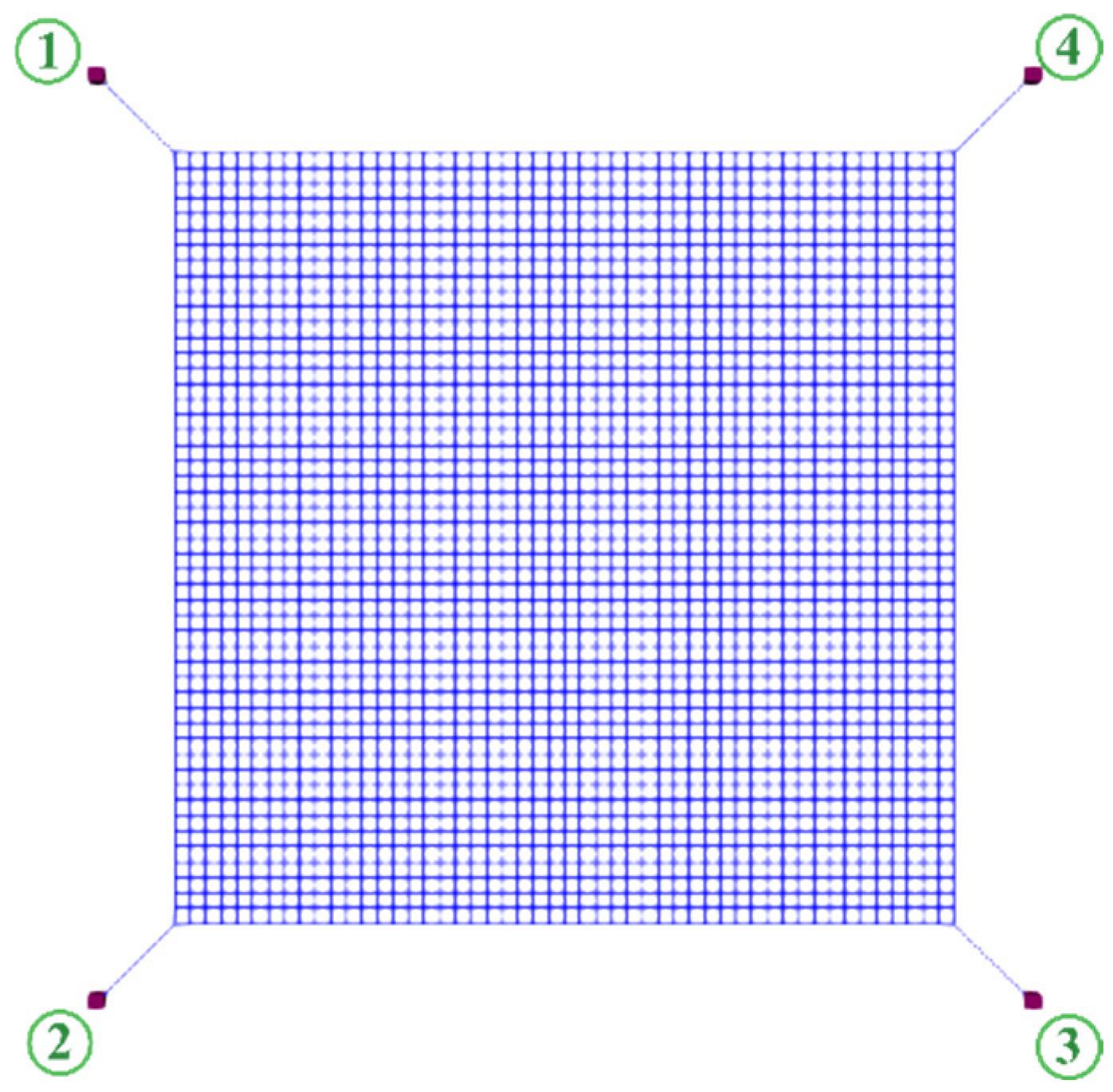
4.1. Design of Simulations

In the simulations, a flexible net is released to capture the debris with different initial rotating velocities. The capture process can be divided into contact and control processes. After coming into contact with the debris, the flexible net drags the debris away under the control of the actuators. The irregular shape of the debris is randomly created by the MATLAB2018a software (MathWorks Company, United States), as shown in Figure 2. The weak gravity force is ignored in the simulations. The deployed configuration of the flexible net is shown in Figure 3. The flexible net has four actuators, each with three engines whose maximum thrusts are 100 N [40,41]. The material of the flexible net is Zylon fiber, which has high strength and is lightweight [33]. The restitution coefficient of the contact dynamics is set as 0.5, which is a little smaller than the experimentally tested value because the net is softer than any other rigid materials [42]. Other simulation parameters of the flexible net and the debris are listed in Table 2 and Table 3, respectively.

4.2. Critical Variables for Evaluating the Capture Process

To gain an insight into the whole capture process, the flexible net and the debris are evaluated in terms of the following variables: (1) Stress of the net thread. The stress of the net threads can be used to evaluate the deformation or safety of the flexible net. (2) Opening area of the flexible net. The opening area of the flexible net is the quadrilateral area formed by the four actuators. This indicator is critical for describing the capture process. (3) Velocities and displacements of four actuators. The velocities and displacements of the four actuators can be utilized to reflect the status of the flexible net. (4) Rotating velocity of the debris. The rotating velocity of the debris indicates the flexible net’s status, which is crucial for evaluating the wrapping stability. (5) Contact force. Contact forces between the flexible net and the debris are critical variables for analyzing the capture process.

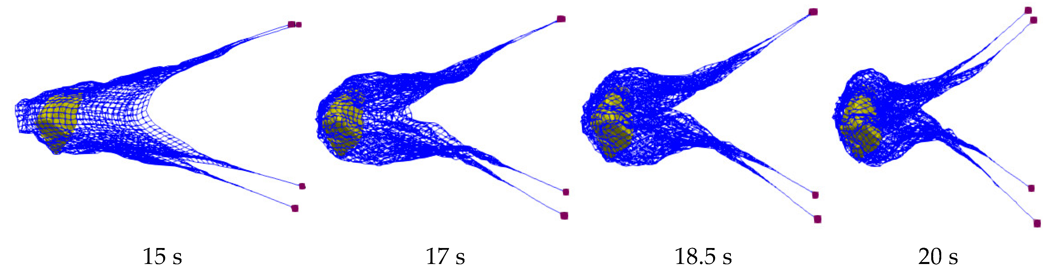
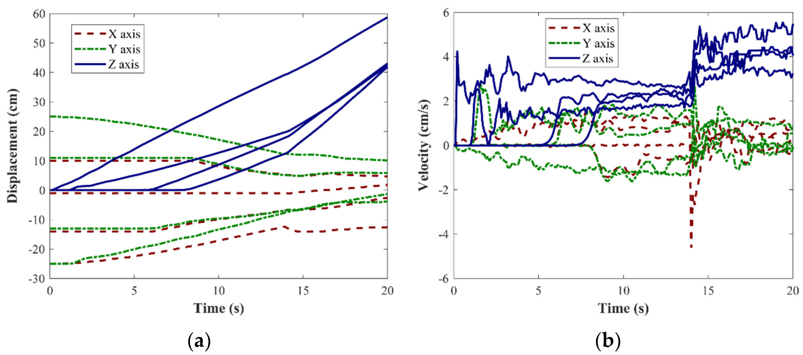
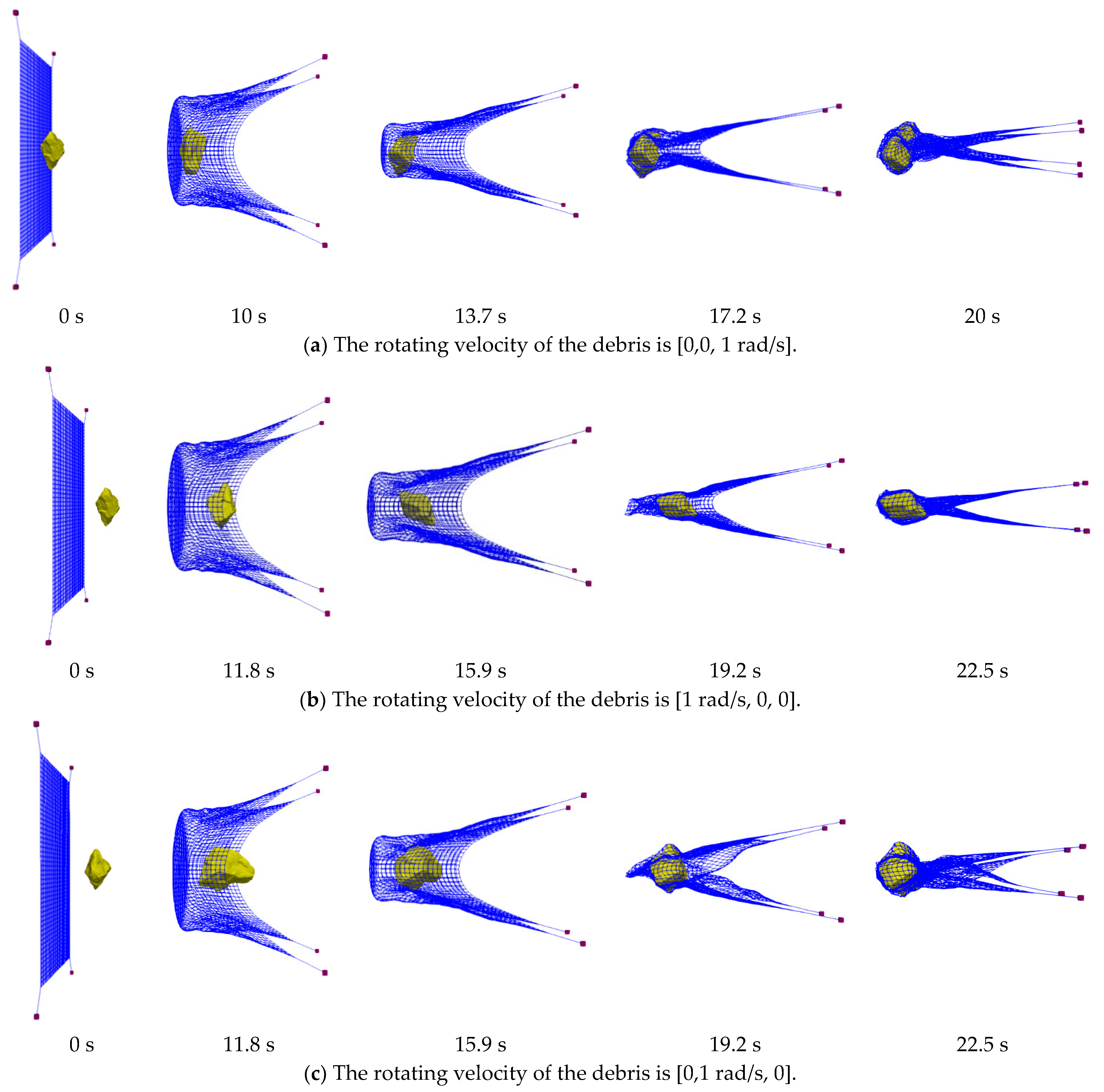
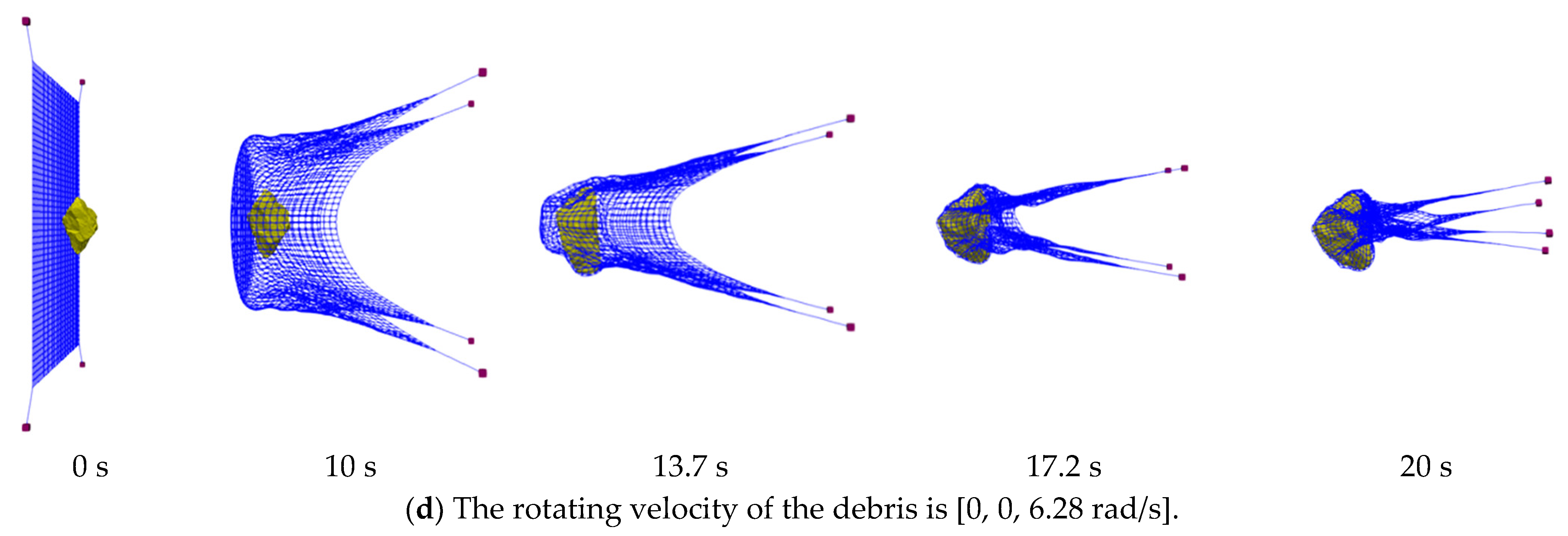
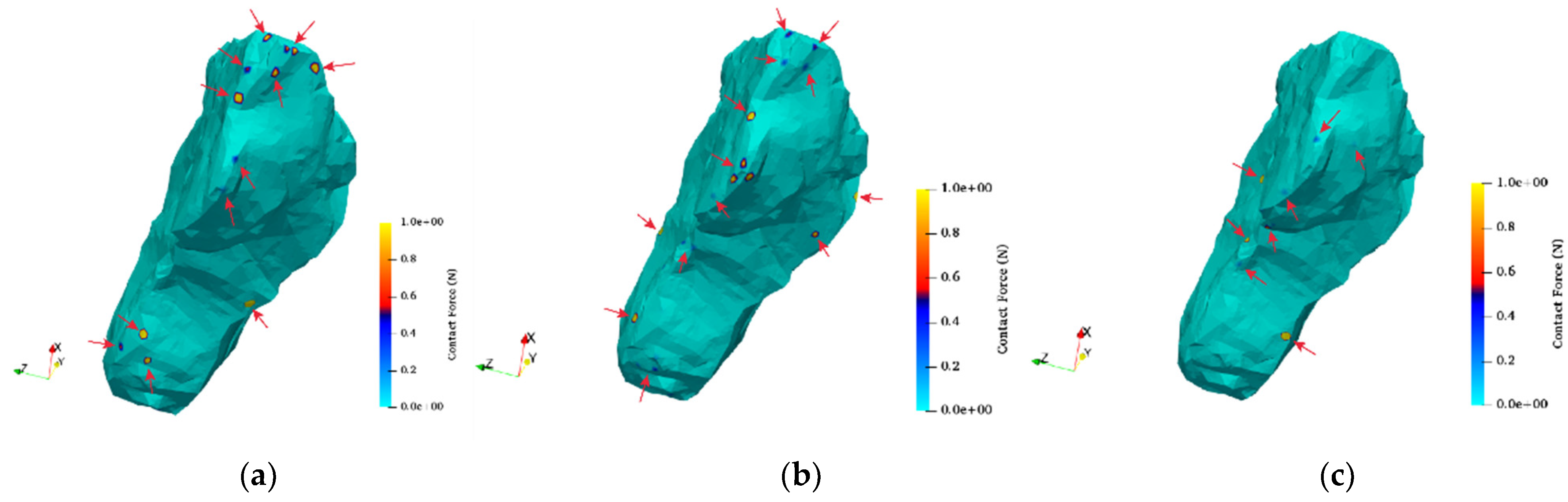
4.3. Simulations and Analysis of the Contact Process

Four groups of capture scenarios were simulated to validate the presented algorithm and the capture scheme: The initial velocity of each actuator of the flexible net was [0, 0, 4 cm/s]. The initial rotating velocity of the debris was 1 rad/s, along each coordinate axis. Additionally, the initial rotating velocity of the debris was 6.28 rad/s along the z-axis for the last simulation.
Figure 4 shows the capture scenarios under different initial conditions. In Figure 4a, it can be seen that the rotating velocity of the debris was 1 rad/s along the z-axis. The initial distance between the flexible net and the debris was 4 cm. The whole simulation time of the contact process was 20 s. The first contact between the flexible net and the debris happened at 13.7 s. As shown in Figure 4a, the debris was fully enveloped by the flexible net. After being enveloped by the flexible net, the debris still rotated with a small velocity. In Figure 4b, it can be seen that the rotating velocity of the debris was 1 rad/s along the x-axis. The whole simulation time of the contact process was 22.5 s. The initial distance between the flexible net and the debris was 10 cm. According to the simulations, if the initial distance between the flexible net and the debris is smaller than 10 cm, the debris cannot be fully enveloped. These results show that the rotation direction of the debris affects the initial condition of the flexible net. The first contact between the flexible net and the debris happened at 16.5 s. The debris was fully enveloped at the time of 22.5 s. In Figure 4c, it can be seen that the rotating velocity of the debris was 1 rad/s along the y-axis. The whole simulation time of the contact process was 22.5 s. The initial distance between the flexible net and the debris was 10 cm. The maximum rotational inertia of the debris was in the y-axis direction. Thus, it is more difficult for the flexible net to capture the debris in this situation. From Figure 4c, it can be seen that the rotation of the debris has a great effect on the deformations of the flexible net. The first contact between the flexible net and the debris happened at 15.7 s. The debris was fully enveloped at the time of 22.5 s.
From the simulations shown in Figure 4a–c, the rotation of the debris decreased within a short time once the debris came into contact with the flexible net. In the time of 20 s, the rotation velocity of the debris nearly decreases to zero. In order to further explore the capture capability of the flexible net, a scenario where a piece of debris with the initial rotating velocity of [0, 0, 6.28 rad/s] is simulated. Figure 4d shows that the initial distance between the flexible netic and the debris was 4 cm. The debris was fully enveloped by the flexible net at the time of 20 s, and the residual rotating velocity was [0.014 rad/s, 0.037 rad/s, 0.086 rad/s]. This result shows the excellent capture capability of the flexible net.

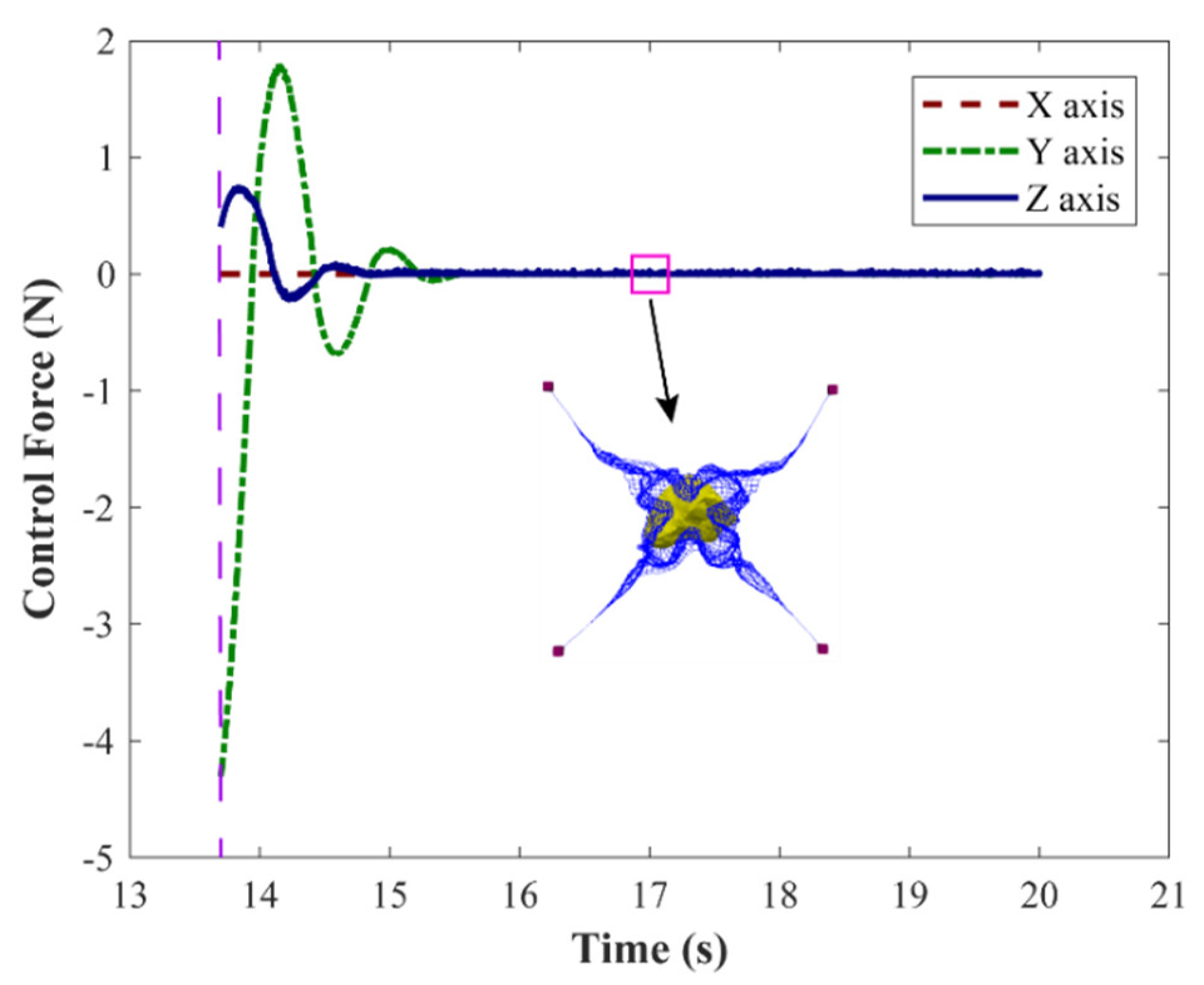
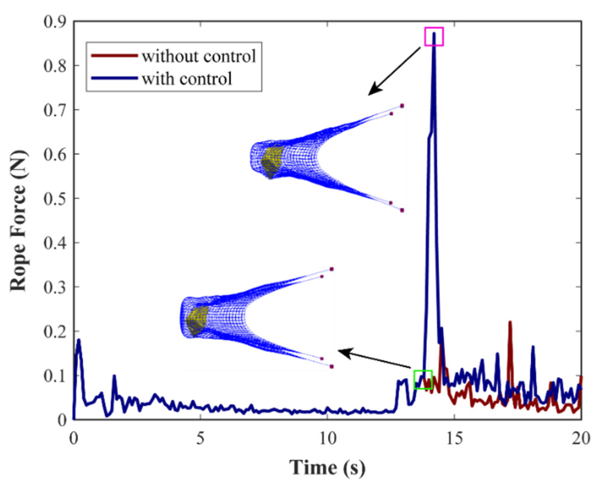
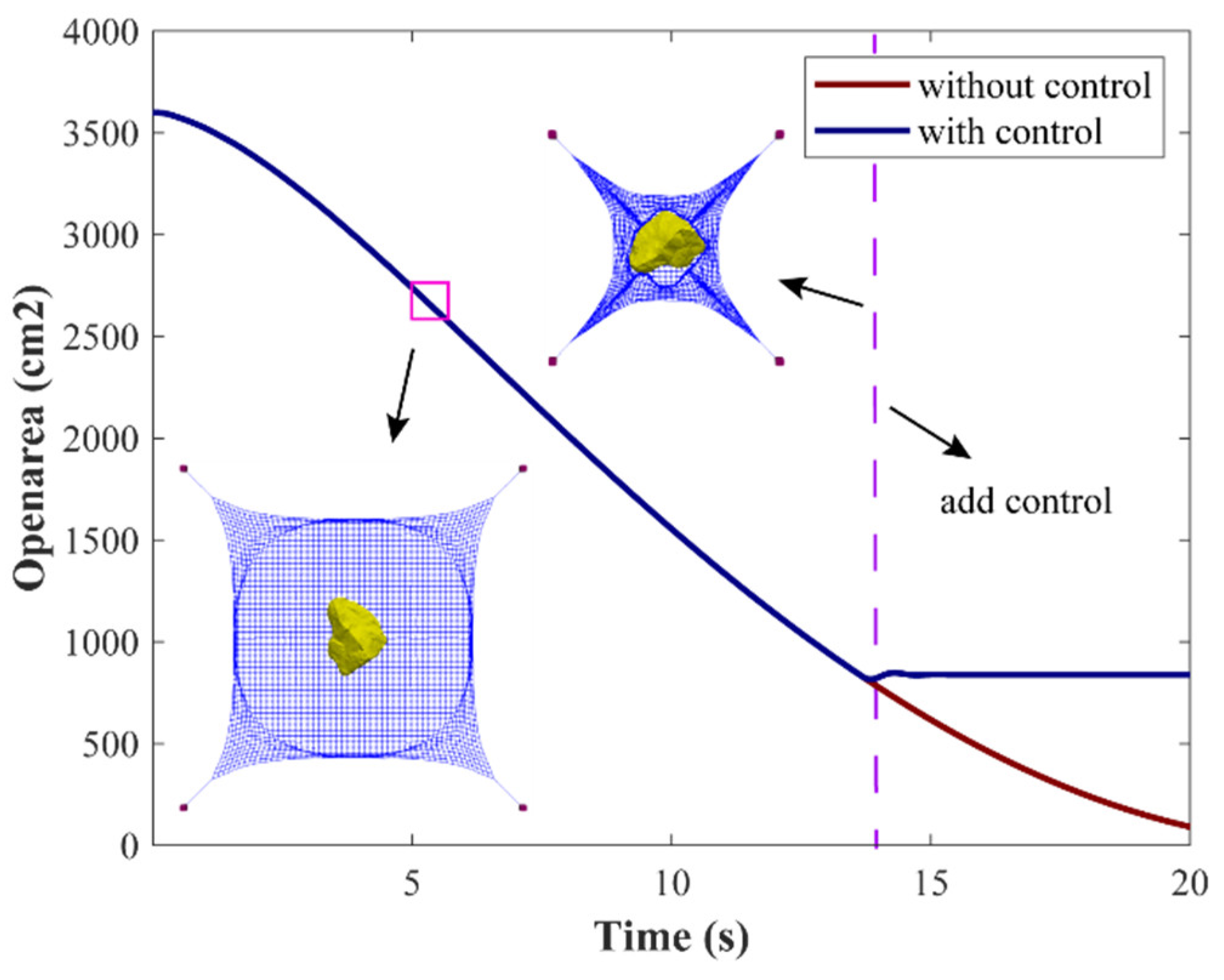
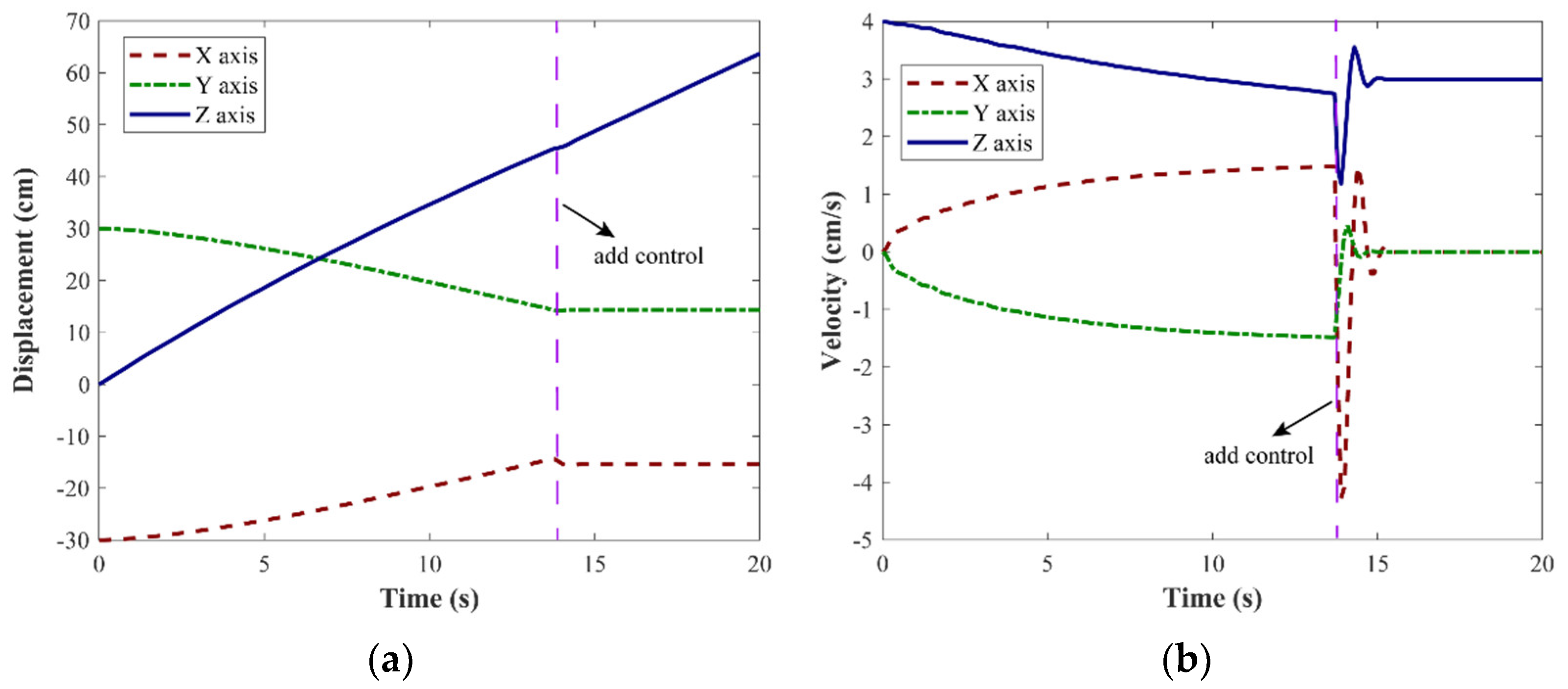
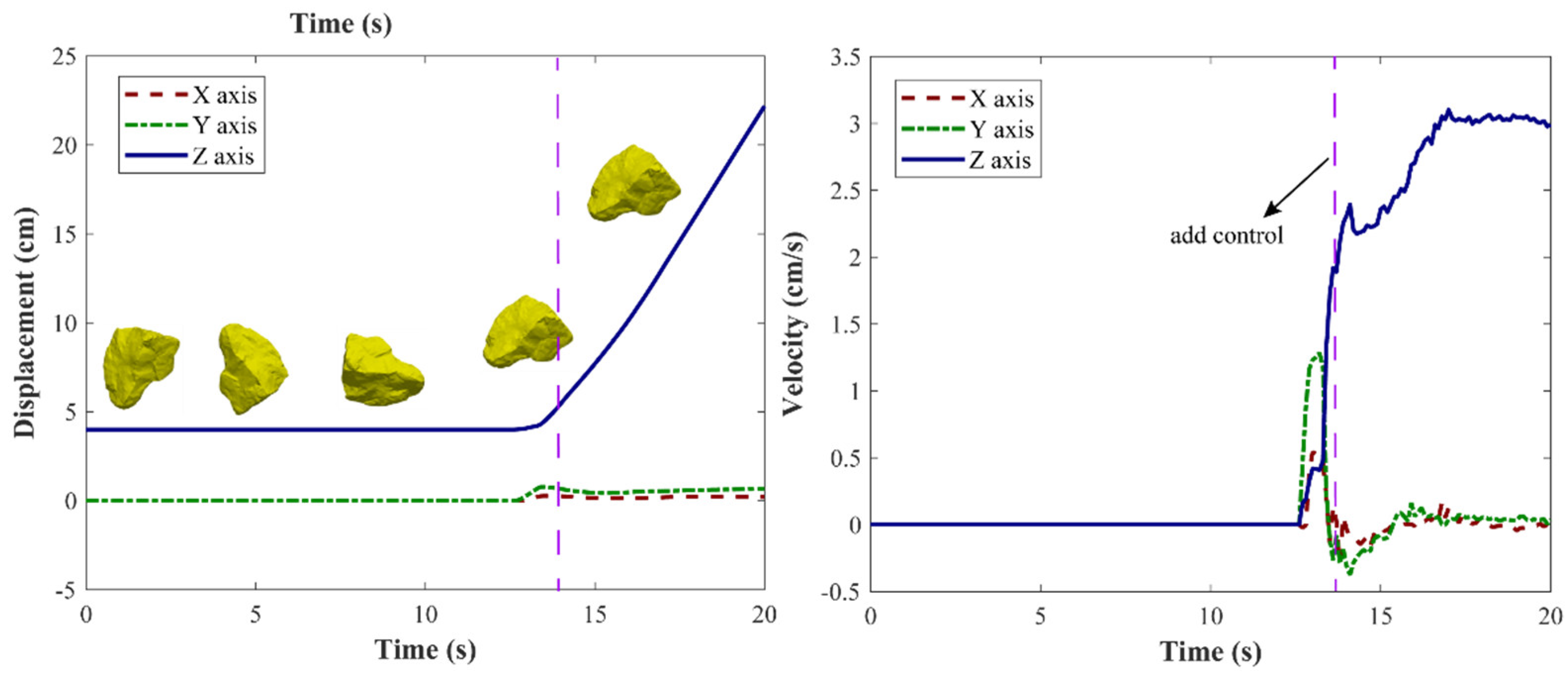
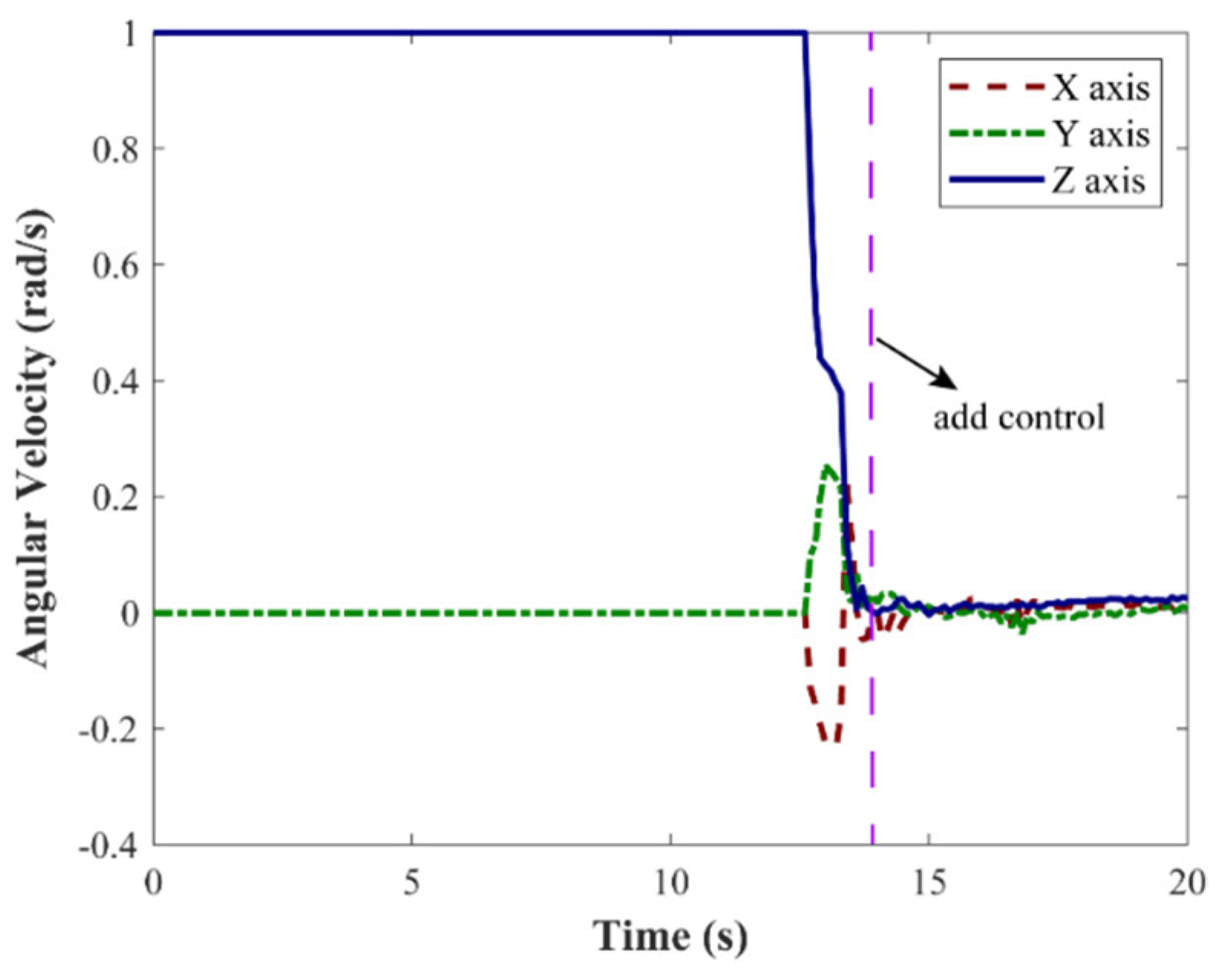
4.4. Simulations and Analysis of the Control Process

In this study, the post-capture process was considered the deorbiting of the debris. The flexible net dragged the debris away from the orbit under the control of the actuators. Taking the capture scenario shown in Figure 2a as an example, the active control scheme started at 13.7 s to avoid potential self-collision between four actuators. The control process after 13.7 s is illustrated in Figure 5, from which we know the debris was fully enveloped and could be dragged away by the flexible net. In the simulations, the target positions of all actuators were [−15, 14, 60] cm, [−14, −14, −45] cm, [14, 14, 45] cm, and [15, 13, 45] cm. The desired trajectory of each actuator was a straight line towards its target position.
The maximum elongation rate of the net material was 3.5%, thus the allowable tension force of each rope thread was 395.84 N. In order to gain an insight into the capture process, the maximum rope forces were derived, as shown in Figure 6. The red line in Figure 6 shows the rope forces of the flexible net without the active control scheme. The maximum tension force was smaller than 0.3 N without the control. From Figure 6, it can be seen that the fluctuation of the rope force after coming into contact with the debris may result from the rotation of the debris. At a time of around 17.2 s, the peak value of the rope force without control occurs, which implies the debris is fully enveloped by the flexible net. In fact, as shown in Figure 4a, the simulation shows that the debris was fully enveloped by the flexible robot at the time of 17.2 s.
When the active control scheme was applied to the actuators, the maximum rope force was 0.87 N, which is much smaller than the allowable tension force of 395.84 N. Thus, the safety of the flexible net can be guaranteed under the presented control scheme. From Figure 5, it can be seen that the maximum value of the rope force occurred just after implementing the control scheme. The fluctuation of the rope force was smaller than 0.2 N after 15 s, meaning that the capture was stable.
Figure 7 shows the opening area of the flexible net. If no control is applied to the actuators, the open area will decrease to zero, thus leading to the debris being fully enveloped. However, once the open area becomes zero, the four actuators will collide with each other. If the actuator is destroyed because of the self-collision, the debris cannot be removed to burn, and the mission fails. Thus, the control scheme is needed to avoid self-collision between the actuators. Meanwhile, the open area of the flexible net should not be too large. The final open area is 839.2552 cm2 under the presented control scheme. Figure 5 validates the active control scheme and the designed trajectory of each actuator. The debris does not escape from the flexible net and can be steadily dragged away.
The wrapping stability of the capture system is partially determined by the motion states of the actuator. In Figure 8, the positions and velocities of the first actuator are shown to describe the capture process. From Figure 8, it can be seen that the velocities in the x and y directions decrease to zero. It can be concluded that the actuator is stabilized to the desired trajectory after 16 s. Other actuators are also stabilized to the desired trajectories according to the results shown in Figure 4 and Figure 7. Furthermore, the positions and velocities of four nodes in the flexible net are illustrated in Figure 9. The displacements and velocities of the nodes are similar to those of the first actuator in the post-capture process. The fluctuations can decrease because of the energy dissipation. The velocity variations in the z-axis are similar to those of the first actuator.
The states of the debris can be used for evaluating the capture process. Figure 10 shows the position and velocity variations of the mass center of the debris. Before applying the control scheme, the debris rotates with a constant angular velocity. After coming into contact with the flexible net, the debris moves with an increasing velocity. After 17 s, the velocity of the mass center of the debris is around 3 cm/s, which is similar to the velocity of the actuator shown in Figure 8b. This velocity coincidence further illustrates that the post-capture period is stable, meaning that the presented control scheme is effective.
Figure 11 shows the angular velocity variations of the debris. From Figure 11, it can be seen that the angular velocity of the debris decreases after it comes into contact with the flexible net, while the translational velocity increases. The angular velocity decreases to zero after the control process starts. All of these phenomena show that the use of this post-capture scheme is feasible for capturing irregular debris. The flexible net could further drag the debris to a lower orbit.
Contact forces can reflect the safety of the flexible net and the stability of the capture process. Figure 12 shows the maximum contact force at each time step. From Figure 12, we can see that the maximum contact force is smaller than 1 N, which implies that the flexible net is safe after the collisions with the debris. The contact positions are distributed along the edges of the debris, and Figure 12 shows that the contact forces decrease throughout the capture process, which means that the capture process becomes more and more stable.
Figure 13 shows the control forces of the first actuator. The maximum control force is much smaller than the allowable value of 100 N. The control forces hardly change after 15.7 s and their values are very small when maintaining the trajectory of the actuator, which implies that a stabilized configuration of the flexible net has been achieved.

5. Conclusions

The debris capture process was simulated by constructing the net dynamics and the debris dynamics. An active net control scheme for dragging the debris was applied to the flexible net. Numerical simulations show that the flexible net has an excellent capture capability under the presented control scheme. The flexible net can capture debris rotating with an angular velocity of 6.28 rad/s. The debris is fully enveloped and stably dragged away by the flexible net in the post-capture process. The interactions between the flexible net and the debris were analyzed in terms of (1) the stress of the net thread, (2) the opening area of the flexible net, (3) the velocities and displacements of four actuators, (4) the rotating velocity of the debris, and (5) the contact forces involved. The results show the wrapping of the debris is stable and the debris can be dragged away along the expected trajectory; thus, this strategy is feasible for use in future missions.

Author Contributions

Conceptualization, M.R., Y.Z. (Yu Zhang) and B.C.; methodology, M.R., Y.Z. (Yu Zhang), B.C., and Y.Z. (Ying Zhan); software, M.R., Y.Z. (Yu Zhang), B.C., and Y.Z. (Ying Zhan); validation, M.R. and Y.Z. (Ying Zhan); formal analysis, M.R., Y.Z. (Yu Zhang), B.C., and Y.Z. (Ying Zhan); investigation, M.R., Y.Z. (Ying Zhan) and B.C.; resources, Y.Z. (Yu Zhang) and B.C.; data curation, M.R., Y.Z. (Yu Zhang), B.C., and Y.Z. (Ying Zhan); writing—original draft preparation, M.R., Y.Z. (Yu Zhang), B.C., and Y.Z. (Ying Zhan); writing—review and editing, M.R., Y.Z. (Yu Zhang), B.C., and Y.Z. (Ying Zhan); visualization, M.R., Y.Z. (Yu Zhang), B.C., and Y.Z. (Ying Zhan); supervision, Y.Z. (Yu Zhang) and B.C.; project administration, Y.Z. (Yu Zhang) and B.C.; funding acquisition, Y.Z. (Yu Zhang) and B.C. All authors have read and agreed to the published version of the manuscript.

Funding

This research was funded by the China Postdoctoral Science Foundation (No. 2021M691743) and the Science and Technology on Space Intelligent Control Laboratory (No. 2021JCJQLB01001).

Institutional Review Board Statement

Not applicable.

Informed Consent Statement

Not applicable.

Conflicts of Interest

The authors declare no conflict of interest.

References

  1. Shan, M.H.; Guo, J.; Gill, E. Review and comparison of active space debris capturing and removal methods. Prog. Aerosp. Sci. 2016, 80, 18–32. [Google Scholar] [CrossRef]
  2. Kessler, D.J.; Burton, G.C.P. Collision frequency of artificial satellites: The creation of a debris belt. J. Geophys. Res. Space Phys. 1978, 83, 2637–2646. [Google Scholar] [CrossRef]
  3. Tarran, B. Prepare for impact: Space debris and statistics. Significance 2021, 18, 18–23. [Google Scholar] [CrossRef]
  4. Houman, H.; Bazzocchi, M.C.F.; Emami, M.R. A deorbiter CubeSat for active orbital debris removal. Adv. Space Res. 2018, 61, 2377–2392. [Google Scholar]
  5. Peters, T.V.; Valero, J.F.B.; Olmos, D.E.; Lappas, V.; Jakowski, P.; Gray, I.; Tsourdos, A.; Schaub, H.; Biesbroek, R. Attitude control analysis of tethered de-orbiting. Acta Astronaut. 2018, 146, 316–331. [Google Scholar] [CrossRef] [Green Version]
  6. Shan, M.H.; Shi, L.L. Post-capture control of a tumbling space debris via tether tension. Acta Astronaut. 2021, 180, 317–327. [Google Scholar] [CrossRef]
  7. Shan, M.H.; Shi, L.L. Comparison of Tethered Post-Capture System Models for Space Debris Removal. Aerospace 2022, 9, 33. [Google Scholar] [CrossRef]
  8. Markus, W.; Clark, C.; Romano, M. Historical survey of kinematic and dynamic spacecraft simulators for laboratory experimentation of on-orbit proximity maneuvers. Prog. Aerosp. Sci. 2019, 110, 100552. [Google Scholar]
  9. Castronuovo, M.M. Active space debris removal—A preliminary mission analysis and design. Acta Astronaut. 2011, 69, 848–859. [Google Scholar] [CrossRef]
  10. Liu, X.-F.; Zhang, X.-Y.; Cai, G.-P.; Chen, W.-J. Capturing a Space Target Using a Flexible Space Robot. Appl. Sci. 2022, 12, 984. [Google Scholar] [CrossRef]
  11. Colmenarejo, P.; Graziano, M.; Novelli, G.; Mora, D.; Serra, P.; Tomassini, A.; Seweryn, K.; Prisco, G.; Gil Fernandez, J. On ground validation of debris removal technologies. Acta Astronaut. 2019, 158, 206–219. [Google Scholar] [CrossRef]
  12. Flores-Abad, A.; Ma, O.; Pham, K.; Ulrich, S. A review of space robotics technologies for on-orbit servicing. Prog. Aerosp. Sci. 2014, 68, 1–26. [Google Scholar] [CrossRef] [Green Version]
  13. Zhao, Y.; Huang, P.; Zhang, F.; Meng, Z. Contact dynamics and control for tethered space net robot. IEEE Trans. Aerosp. Electron. Syst. 2018, 55, 918–929. [Google Scholar] [CrossRef]
  14. Botta, E.M.; Sharf, I.; Misra, A.K. Contact dynamics modeling and simulation of tether nets for space-debris capture. J. Guid. Control Dyn. 2017, 40, 110–123. [Google Scholar] [CrossRef]
  15. Dudziak, R.; Tuttle, S.; Barraclough, S. Harpoon technology development for the active removal of space debris. Adv. Space Res. 2015, 56, 509–527. [Google Scholar] [CrossRef]
  16. Sizov, D.A.; Aslanov, V.S. Space debris removal with harpoon assistance: Choice of parameters and optimization. J. Guid. Control Dyn. 2020, 44, 767–778. [Google Scholar] [CrossRef]
  17. Huang, P.; Zhang, F.; Chen, L.; Meng, Z.; Zhang, Y.; Liu, Z.; Hu, Y. A review of space tether in new applications. Nonlinear Dyn. 2018, 94, 1–19. [Google Scholar] [CrossRef]
  18. Lim, J.; Chung, J. Dynamic analysis of a tethered satellite system for space debris capture. Nonlinear Dyn. 2018, 94, 2391–2408. [Google Scholar] [CrossRef]
  19. Zhang, Y.; Yu, Y.; Baoyin, H. Dynamical behavior of flexible net spacecraft for landing on asteroid. Astrodynamics 2021, 5, 249–261. [Google Scholar] [CrossRef]
  20. Sharf, I.; Thomsen, B.; Botta, E.M.; Misra, A.K. Experiments and simulation of a net closing mechanism for tether-net capture of space debris. Acta Astronaut. 2017, 139, 332–343. [Google Scholar] [CrossRef]
  21. Shan, M.; Guo, J.; Gill, E. Contact dynamics on net capturing of tumbling space debris. J. Guid. Control Dyn. 2018, 41, 2063–2072. [Google Scholar] [CrossRef] [Green Version]
  22. Zhao, Y.; Huang, P.; Zhang, F. Capture dynamics and net closing control for tethered space net robot. J. Guid. Control Dyn. 2019, 42, 199–208. [Google Scholar] [CrossRef]
  23. Zhao, Y.; Zhang, F.; Huang, P.F. Capture dynamics and control of tethered space net robot for space debris capturing in unideal capture case. J. Frankl. Inst. 2020, 357, 12019–12036. [Google Scholar] [CrossRef]
  24. Zhao, Y.; Zhang, F.; Huang, P.F. Dynamic Closing Point Determination for Space Debris Capturing via Tethered Space Net Robot. IEEE Trans. Aerosp. Electron. Syst. 2022. [Google Scholar] [CrossRef]
  25. Riccardo, B.; Salvi, S.; Lavagna, M. Dynamics analysis and GNC design of flexible systems for space debris active removal. Acta Astronaut. 2015, 110, 247–265. [Google Scholar]
  26. Si, J.; Pang, Z.; Du, Z.; Cheng, C. Dynamics modeling and simulation of self-collision of tether-net for space debris removal. Adv. Space Res. 2019, 64, 1675–1687. [Google Scholar] [CrossRef]
  27. Endo, Y.; Kojima, H.; Trivailo, P.M. Study on acceptable offsets of ejected nets from debris center for successful capture of debris. Adv. Space Res. 2020, 66, 450–461. [Google Scholar] [CrossRef]
  28. Botta, E.M.; Miles, C.; Sharf, I. Simulation and tension control of a tether-actuated closing mechanism for net-based capture of space debris. Acta Astronaut. 2020, 174, 347–358. [Google Scholar] [CrossRef]
  29. Shan, M.; Guo, J.; Gill, E. An analysis of the flexibility modeling of a net for space debris removal. Adv. Space Res. 2020, 65, 1083–1094. [Google Scholar] [CrossRef]
  30. Hou, Y.; Liu, C.; Hu, H.; Yang, W.; Shi, J. Dynamic computation of a tether-net system capturing a space target via discrete elastic rods and an energy-conserving integrator. Acta Astronaut. 2021, 186, 118–134. [Google Scholar] [CrossRef]
  31. Si, J.; Pang, Z.; Du, Z.; Fu, J. Dynamics modeling and simulation of a net closing mechanism for tether-net capture. Int. J. Aerosp. Eng. 2021, 2021, 8827141. [Google Scholar] [CrossRef]
  32. Shan, M.; Guo, J.; Gill, E. Deployment dynamics of tethered-net for space debris removal. Acta Astronaut. 2017, 132, 293–302. [Google Scholar] [CrossRef]
  33. Gardsback, M.; Tibert, G. Deployment control of spinning space webs. J. Guid. Control Dyn. 2009, 32, 40–50. [Google Scholar] [CrossRef]
  34. Zhang, F.; Huang, P.; Meng, Z.; Zhang, Y.; Liu, Z. Dynamics analysis and controller design for maneuverable tethered space net robot. J. Guid. Control Dyn. 2017, 40, 2828–2843. [Google Scholar] [CrossRef]
  35. Zhang, Y.; Feng, R.; Yu, Y.; Liu, J.; Baoyin, H. Asteroid Capture Dynamics and Control using a Large-scale Flexible Net. IEEE Trans. Aerosp. Electron. Syst. 2022. [Google Scholar] [CrossRef]
  36. Zhong, R.; Xu, S. Neural-network-based terminal sliding-mode control for thrust regulation of a tethered space-tug. Astrodynamics 2018, 2, 175–185. [Google Scholar] [CrossRef]
  37. Zhang, N.; Zhang, Z.; Baoyin, H. Timeline Club: An optimization algorithm for solving multiple debris removal missions of the time-dependent traveling salesman problem model. Astrodynamics 2022, 6, 219–234. [Google Scholar] [CrossRef]
  38. Schwartz, S.R.; Richardson, D.C.; Michel, P. An implementation of the soft-sphere discrete element method in a high-performance parallel gravity tree-code. Granul. Matter 2012, 14, 363–380. [Google Scholar] [CrossRef]
  39. Ferellec, J.F.; McDowell, G.R. A method to model realistic particle shape and inertia in DEM. Granul. Matter 2010, 12, 459–467. [Google Scholar] [CrossRef]
  40. Bierhaus, E.B.; Clark, B.C.; Harris, J.W.; Payne, K.S.; Dubisher, R.D.; Wurts, D.W.; Hund, R.A.; Kuhns, R.M.; Linn, T.M.; Wood, J.L.; et al. The OSIRIS-REx spacecraft and the touch-and-go sample acquisition mechanism (TAGSAM). Space Sci. Rev. 2018, 214, 107. [Google Scholar] [CrossRef] [Green Version]
  41. Yoshikawa, K.; Sawada, H.; Kikuchi, S.; Ogawa, N.; Mimasu, Y.; Ono, G.; Takei, Y.; Terui, F.; Saiki, T.; Yasuda, S.; et al. Modeling and analysis of Hayabusa2 touchdown. Astrodynamics 2020, 4, 119–135. [Google Scholar] [CrossRef]
  42. Biele, J.; Kesseler, L.; Grimm, C.D.; Schröder, S.; Mierheim, O.; Lange, M.; Ho, T.M. Experimental determination of the structural coefficient of restitution of a bouncing asteroid lander. arXiv 2017, arXiv:1705.00701. [Google Scholar]
  43. Abd, E.; Afaf, M.; Abdel, Y.A. Aluminium Alloys in Space Applications: A Short Report. J. Appl. Sci. Eng. 2021, 22, 1–7. [Google Scholar]
Figure 1. Flowchart of the presented capture dynamics method.
Aerospace 09 00299 g001
Figure 2. Shape model of the debris in the simulations.
Aerospace 09 00299 g002
Figure 3. The deployed configuration of the flexible net with four actuators.
Aerospace 09 00299 g003
Figure 4. Capture scenarios under different initial conditions. (a) The rotating velocity of the debris is [0, 0, 1 rad/s]. (b) The rotating velocity of the debris is [1 rad/s, 0, 0]. (c) The rotating velocity of the debris is [0,1 rad/s, 0]. (d) The rotating velocity of the debris is [0, 0, 6.28 rad/s].
Aerospace 09 00299 g004aAerospace 09 00299 g004b
Figure 5. The post-capture process with the presented active control scheme.
Aerospace 09 00299 g005
Figure 6. Rope force of the net threads during the capture and control process.
Aerospace 09 00299 g006
Figure 7. The opening area of the flexible net during the capture and the control process.
Aerospace 09 00299 g007
Figure 8. Position and velocity variations of the first actuator during the capture process. (a) Position variations of the first actuator. (b) Velocity variations of the first actuator.
Aerospace 09 00299 g008
Figure 9. Position and velocity variations of four stochastic net nodes. (a) Position variations of four stochastic net nodes. (b) Velocity variations of four stochastic net nodes.
Aerospace 09 00299 g009
Figure 10. The position and velocity variations of the mass center of the debris.
Aerospace 09 00299 g010
Figure 11. The angular velocity variations of the debris.
Aerospace 09 00299 g011
Figure 12. Contact positions on the debris. (a) 13.7 s, (b) 17 s, and (c) 20 s.
Aerospace 09 00299 g012
Figure 13. Contact forces during the capture and control process.
Aerospace 09 00299 g013
Table 1. Comparisons of the proposed method with the previous methods.
Comparison IndicatorsLiterature
[21]
Literature
[22,23,24]
Literature
[25]
Literature
[26]
Literature
[29]
Literature
[28]
Literature
[29]
Literature
[30]
Literature
[31]
Our Study
Modeling method of the netKelvin–Voigt methodKelvin–Voigt methodKelvin–Voigt methodKelvin–Voigt methodKelvin–Voigt methodKelvin–Voigt methodKelvin–Voigt method
&
the ANCF method
The discrete elastic rods methodKelvin–Voigt methodKelvin–Voigt method
Consider the post-capture process?nonoyesnonoyesnononoyes
Consider the translational dynamics of the debris?yesnoyesnonoyesnononoyes
Consider the rotational dynamics of the net?yesnoyesnonoyesnononoyes
Net closing mechanismMechanical mechanism (e.g., spring)Active control schemeMechanical mechanism (e.g., spring)No mechanismNo mechanismMechanical mechanism (e.g., spring)Mechanical mechanism (e.g., spring)No mechanismThe split closing mechanismActive control scheme
Can the net be reopened?noyesnononononononoyes
Can many pieces of debris be removed in one mission?noyesnononononononoyes
Consider the self-collision of the net?nononoyesnononononono
Consider the capture robustness?nonononoyesnonononono
Simulation softwarenononononoVortex Studionononono
Table 2. Simulation parameters of the debris.
ParameterValue
Mass mT308.7747 g
MaterialAluminum alloy [43]
Dimensions5 cm × 13 cm × 10 cm
Restitution coefficient0.5 [42]
Frictional angle 45° [35]
Table 3. Simulation parameters of the flexible net.
ParameterValue
Mass of each actuator mk10 kg
Maximum deployment area3600 cm2
MaterialZylon fiber
Density1440 kg/m3
Thread diameter2 mm
Initial thread length4 cm
Young’s modulus180 GPa
Damping ratio0.5
Publisher’s Note: MDPI stays neutral with regard to jurisdictional claims in published maps and institutional affiliations.

