1. Introduction
Liquid rocket engines are the main power devices in current space transportation and space flight. With the increase in space exploration and operation activities, considerable requirements have been raised for the variable-thrust engine technology [
1,
2,
3]. Moreover, numerous liquid rocket engine thrust adjustment technologies [
1,
2,
3] have been developed, among which the method of the fixed-geometry injector with a variable flow of propellant is relatively simple. This method adjusts the pressure of the propellant feed system or control valves in the propellant lines to realize the change in the flow injected in the thrust chamber and thus adjust the thrust. The engine injector needs to work under different flow conditions. In other words, the injector with fixed geometry needs to work under different injection pressure drop conditions. As an important component of the liquid rocket engine, the injector determines the quality of spray atomization of the propellant. The atomization characteristics of the injector under different flow conditions greatly influence engine stability and performance. The swirl injector can obtain good atomization quality and high mixing efficiency; thus, it has been widely used in liquid rocket engines, gas turbine engines, diesel engines, and other combustion devices. Two types of swirl injectors, namely, the screw conveyor swirl injector and the tangential inlet swirl chamber injector, are widely used.
Considerable research has been conducted on tangential inlet swirl chamber injectors. Li-Jun Yang et al. [
4] studied the atomization characteristics of a swirl coaxial injector by using a high-speed photographic technique and obtained the influence law of recess length on atomization. Chad J. Eberhart et al. [
5] studied the influence of the mass flow rate on the atomization characteristics of a swirl injector by using the backlit and stroboscopic imaging techniques and the Phase Doppler Particle Analyzer (PDPA) and indicated that the mass flow rate has no effect on spray angle. Ji-Hyuk Im et al. [
6] performed experimental research on the atomization characteristics of gas-liquid swirl coaxial injectors by combining photography and image processing and distinguished the gas- and liquid-centered swirl coaxial injectors in atomization characteristics. Chad J. Eberhart et al. [
7] researched the effect of chamber pressure on the spray characteristics of a swirl injector by using backlit and stroboscopic visualization techniques and the PDPA system. Qing-Fei Fu et al. [
8] evaluated the influences of the geometric parameters of an open-end swirl injector on liquid film thickness, spray angle, and dynamic characteristics. Ingyu Lee et al. [
9] conducted experimental research on the effect of an oxygen/fuel ratio on the atomization characteristics of a double-swirl coaxial injector and obtained the influence law of the oxygen/fuel ratio on the spray angle and average particle diameter. Qing-fei Fu et al. [
10] studied the influences of different ambient pressures on the spray angle and breakup length of a swirl injector by using high-speed photography technology. Chen Chen et al. [
11] researched the influences of different pressure drops and ambient pressures on the spray angle and discharge coefficient of an open-end swirl injector and obtained the images of the atomization field by using a high-speed shadowgraph system. Rahul Anand et al. [
12] studied the influences of the swirl number and recess ratio on the atomization characteristics of a gas-centered swirl coaxial injector and analyzed the particle size by using a Malvern particle sizer.
However, minimal research has been conducted on screw conveyer swirl injectors. Guohui Wang et al. [
13] performed a numerical simulation and a cold flow experiment on a screw conveyer swirl injector and obtained the influence law of the structure of the screw conveyor on the atomization characteristics. According to their research results, reducing the size of the normal section area of the helical groove can increase the injector outlet speed and improve the atomization quality, but cannot change the size of the atomization angle. By changing the helix angle, the maximum speed of the injector outlet and the atomization half-angle can be changed. Under a certain flow rate, there is an optimal helix angle. Changing the number of channels can also change the half-angle of atomization and affect the quality of atomization. Fewer channels require a higher differential pressure to meet the flow design point. The results of the numerical simulation and the cold flow experiment are in good agreement. In this study, experiments were carried out under different flow rate conditions, but only the atomization angle was used as an index to measure the atomization effect, and the change in particle size was not considered. Ahmad Hussein Abdul Hamid et al. [
14] studied the influences of the Reynolds number, injection pressure drop, and injection pressure on the performance of a screw conveyor swirl injector and acquired the influence law on the discharge coefficient, spray angle, and breakup length through cold flow experiments with water as a single working fluid. Gregor Schlieben et al. [
15] performed thermal experimental research on the influences of different injector configurations on combustion stability and emphasized that the configuration of the gas injector does not significantly affect combustion stability, and instead the geometry of the screw conveyor swirl fuel injector highly influences combustion stability. There is no reference in this research to the change in mass flow rate. Zhongtao Kang et al. [
16] conducted cold flow experimental research on the atomization characteristics of a screw conveyor swirl injector and obtained the spray angle by using image processing and a Sauter mean diameter by using PDA. This paper mainly studies the influence of the gas-liquid ratio on the spray characteristics of the gas-liquid coaxial double centrifugal injector. Xuan Li et al. [
17] performed a cold flow experiment and numerical calculation research on the atomization characteristics of an oxygen-centered kerosene-swirl coaxial injector, conducted an atomization field analysis of the cold flow experiment by using a high-speed camera and image-processing technologies, and provided the influence law of the momentum flow ratio on a spray angle. In this study, as the momentum flux ratio changes, the mass flow rate changes to some extent. However, the range of flow variation is small (within an order of magnitude). Therefore, this study cannot be used as a reference for variable working conditions. Only the atomization angle is analyzed by using high-speed photography and image processing; the particle diameter of the atomization field is not analyzed. Most of the research on the atomization characteristics of two types of swirl injectors performed by researchers has focused on the influences of geometric configuration, ambient pressure, and other parameters on the atomization characteristics. In the research methods, these researchers have mostly used cold flow experiments to study the atomization characteristics of injectors and acquired the atomization characteristic parameters by using high-speed photography technology, backlit and stroboscopic visualization techniques, PDPA, and the Malvern particle sizer. However, there are few studies on average particle sizes using high-speed photography and image-processing methods. The research on the working characteristics of swirl injectors under different mass flow rates has been relatively limited, however, this aspect is important for thrust-adjustable engines.
In the summary of previous work, we can find that PDPA technology and high-speed photography technology are widely used in atomization research. PDPA technology can obtain accurate particle size distribution at a certain distance from the injector, however, it is difficult to give very intuitive information about the situation of the entire atomization field, such as the evolution of the atomization process and the atomization angle in steady-state atomization. High-speed photography technology can make up for the shortcomings of PDPA technology; however, this technology has a large deviation in the measurement results of particle size. The combination of the two methods can play a complementary effect. National Instrument’s Vision Assistant software is often used for image processing. Avinash Kumar Agarwal et al. [
18] used National Instrument’s Vision Assistant 2009 software for image processing to study the effect of ambient pressure on macroscopic spray parameters, such as spray tip penetration, spray cone angle and spray area, of mineral diesel, Karanja oil (K100) and blends (K5, K20). M. Roudini et al. [
19], using National Instrument’s Vision Assistant software to study the effects of different nozzle geometries and different test conditions on the atomization performance (liquid ligament rupture length, location of each atomized area) of prefilming air-blast atomizers. Cold flow experiments of injector atomization characteristics can use water as a medium. Krishna Ahuja et al. [
20] designed a shear coaxial injector with central kerosene and outer N
2O. They performed cold flow experiments with water and nitrogen, and studied the atomization angle, breaking length, droplet size, and other atomization characteristics. Finally, the ignition test was carried out using kerosene and N
2O, and the flame stability was observed. The results show that after improving the relevant parameters through the cold flow experimental results, the atomization effect of kerosene/N
2O can be improved, and the flame stability can be enhanced. Kenny et al. [
21] studied the effects of combustion chamber back pressure on the atomization characteristics of a swirl injector by replacing liquid oxygen and gaseous fuel with water and nitrogen by cold flow experiments. It was concluded that the increase in backpressure will increase the liquid film thickness and reduce the atomization angle, and finally increase its discharge coefficient. The above studies show that the replacement of liquid propellant with water can obtain some common laws.
In this study, a cold flow experiment with water was conducted to investigate the atomization characteristics of two screw conveyor swirl injectors under different mass flow rates. The atomization parameters were acquired by combining high-speed photography, image processing, and PDPA technologies. The motivation for this research is as follows: (1) To study the influence law of the mass flow rate on the atomization effect of the screw conveyor swirl injector, and to give the selection criteria of the design point, so as to guide the design of the injector. (2) By using PDPA and image technology, we can analyze the average particle size d32 of different flows at the same location, highlight the advantages of PDPA technology in atomization analysis, and discuss the method to improve the accuracy of particle size calculation with image technology.
2. Test System and Experimental Method
A cold flow experiment on screw conveyor swirl injectors is conducted by using high-speed photography and PDPA technologies to obtain the characteristic parameters of the spray field. Water is used as the test medium in the test. The test system is mainly composed of a water supply system, injector, data acquisition, PDPA system, and high-speed camera. The water supply system adopts the extrusion supply mode (as shown in
Figure 1). The system controls the flow through an orifice and tests the flow value by using a flow meter. The water tank pressures, pressures before and after the orifice, and pressure in front of the injector on the test pipeline are also tested.
The PDPA system uses the product of TSI. The system is mainly composed of a laser generator, transmitter, laser coupler, laser receiver, RSA signal processor, optical driver, photomultiplier tube, Doppler signal analyzer, and data-processing system. The particle size range that it can test is 0.5 µm to 300 µm with a test accuracy of 0.5%. A flow sizer was used to analyze the flow field. The system can provide the size distribution of the liquid spray and the circumferential and axial velocities of the particles.
The experiment uses a Phantom MIRO M340 camera. The resolution is 2560 × 1600, the sampling frequency is 24 frames per second and the exposure time is 14,000 µs. The working time of each test of SCS-1 (from opening to closing of the cut-off valve) is about 70 s, and the working time of each test of SCS-2 is about 60 s. A total of 2052 photos were collected in each experiment, and the collection time was about 82 s to ensure that the entire process from the start of atomization to the steady-state atomization and the end of the experiment was captured. The experiment was completed in December, and the experiments on each working condition of SCS-1 were completed in the afternoon and evening. The experiments on each working condition of SCS-2 were completed in the morning and evening. Considering that the experiments were carried out at different times, the ambient lighting conditions may have some influence on the results. Therefore, we placed a fluorescent lamp to supplement the lighting, and a smooth white plastic plate was used as the background plate. In this way, the influence of the ambient lighting conditions on the experiment would be minimized.
With the help of the National Instruments Vision Assistant image-processing software, the atomization pictures obtained can be processed to obtain the diameter of the atomized droplets and the size of the atomization angle. Taking SCS2-5 as an example, the main steps in the image-processing process are as follows: (1) Because the default coordinate system in the imaging system is the pixel coordinate system rather than the real length coordinate system, it is necessary to find the correspondence between the two different coordinate systems by calibrating the image. Therefore, select the point distance calibration in the calibration function (convert the pixel coordinate system to the real coordinate system through the known real size). In order to reduce the error, the nozzle height is selected as the real size for calibration, and the corresponding relationship obtained after calibration is 0.1458 mm/pixels. (2) After the calibration is complete, the image needs to be corrected for subsequent processing. (3) Adjust the brightness, contrast, and gamma value of the image through the brightness adjustment function and enhance the color difference between the background color and the foggy area. (4) Use the color plane extraction function to extract the value plane and convert the fog image from a color image to a grayscale image. (5) Use the lookup table function in the grayscale function to change the contrast between the dark and bright areas. (6) Use appropriate closing operations in the grayscale morphology function to remove isolated dark spots in bright areas and appropriately smooth the boundaries of dark areas. (7) Use the metric function in the threshold function to binarize the grayscale image. It can be seen that the thresholding function not only completely extracts the atomization area but also extracts the nozzle structure, which is determined by the processing material of the nozzle. (8) Select “Remove Large Particles” in the binary function to extract particles with smaller boundaries in the atomized area, and then apply functions, such as filling holes and particle filtering to filter larger droplets that have been fused together. (9) Through the circle detection function, the droplet diameter can be obtained. The processing results of each step are shown in
Figure 2.
Based on the requirement of an RBCC prototype for a liquid rocket engine with variable working conditions, the gas-oxygen/JP-10 rocket engine needs to be able to operate at a mass flow of 75–600 g/s, thrust chamber pressure of 1–8 MPa, and oxygen-fuel ratio in the range of 1.4–2.6. According to the above indicators and the actual work needed, we selected five operating points, as shown in
Table 1.
Since the total propellant flow (75~600 g/s) is relatively large, we choose three screw conveyor swirl injectors to work together to meet the required flow range. In this study, the flow operating point of a single JP-10 injector in
Table 1 was taken as a reference and designed as the working condition point for the cold flow experiments of SCS-1 and SCS-2. The mass flow rate of the design point is 26.2 g/s and the pressure drop is 4.2 MPa for SCS1; the mass flow rate of the design point is 49.2 g/s and the pressure drop is 1.8 MPa for SCS2. According to the selection of design points, the geometric parameters of injection can be designed. Swirl motion is conferred to the fuel through the spiral channel. Two screw conveyor swirl injectors, SCS1 and SCS2, are designed on the basis of the numerical simulation of the influences of the helix angle and number of spiral grooves on the atomization characteristics. The design process is as follows: (1) Given mass flow rate, atomization angle, injector pressure drop, and physical properties of propellant. (2) According to the preliminary selection of flow rate, pressure drop, atomization angle, and flow coefficient at the design point, the value of geometric characteristic A of the nozzle can be obtained by querying the design experience table to be 2.7. (3) Solve the diameter of the injector outlet. (4) Select the radial location of the center of the tangential channel. (5) Give the number of helical grooves of the screw conveyor. (6) Give the helix angle of the screw conveyor. (7) Solve the normal section area of the helical groove of the screw conveyor (assuming the helical groove is rectangular). (8) Solve the width and height of the helical groove normal section area. (9) Solve the external diameter of the screw conveyor. (10) Solve the inner diameter of the screw conveyor. (11) Solve the length of the screw conveyor. Since this research studies the effects of different mass flow rates on the atomization of the screw conveyor swirl injectors, making A of SCS-1 and SCS-2 as equal as possible is to prevent the different geometric characteristics from affecting the atomization characteristics.
The structure diagram of the screw conveyor swirl injectors is shown in
Figure 3. The specific parameters of the two injectors are shown in
Table 2, and the characterization of some parameters is shown
Figure 4. Theoretically, the cold flow atomization experiment is conducted on the two injectors in the flow range of 10.4 g/s to 55.6 g/s. The theoretical calculation of the mass flow value for each experimental condition is shown in
Table 3.
3. Analysis and Discussion
Due to the processing error of the injector and the measurement error existing in the experiment, there is a certain gap between the actual flow rate and the designed flow rate. In fact, the atomization and cold flow experiment within the flow range of 9.5 g/s to 84 g/s were performed on SCS1 and SCS2 injectors (The accuracy of the flow meter used in the experiment is 5%). In the experiment, the flow of the injectors was adjusted by changing the orifice plate. The experimental conditions are shown in
Table 4. The photographs of the atomization field were taken by high-speed photography, and the particle sizes in the atomization field were analyzed by PDPA.
3.1. Atomization Process Analysis
The atomization process of the two injectors under different flow conditions was analyzed by high-speed photography technology to obtain the atomization images under different working conditions. High-speed photography can capture the entire process of the injectors from the beginning of atomization to the steady-state atomization carefully. Here, only the typical images are given for analysis. The typical images of the atomization process are shown in
Table 5 and
Table 6.
The detailed process of injector atomization can be clearly observed from the sequence images of the atomization process in
Table 5 and
Table 6. At the beginning of the spray, without pressure, the spray is moved away from the injector in the column. Low pressure was then produced in the injector, which caused the liquid to produce a certain axial speed and thus promoted the liquid to develop downstream. The liquid had a certain rotational speed when moving away from the injector under the effect of centrifugal force due to the existence of a cyclone in the injector. The speed was converted into the radial and tangential velocities of the liquid flow in a short time. As a result, the radial size of the liquid flow increased rapidly, which caused its conical shape to gradually expand. However, this trend would not develop indefinitely. With the continuous expansion of the conical surface of the liquid flow, its surface tension increased, and the curvature radius of the surface decreased accordingly. They determined the jet shape of the liquid flow together. When the liquid flow developed to a certain peak in the radial direction, affected by the surface tension, it began to shrink. At the same time, the rotation of the liquid flow began to increase, which restricted the shrinkage development. The liquid flow expanded again when it shrunk to the place near the central axis of the injector and then continued to expand, shrink, re-expand, and re-shrink. Therefore, at the beginning of the spray, the liquid flow exhibited a periodic motion in a figure-eight shape along the axis. With the increase in pressure, the liquid flow remained dispersed in the radial direction in the hollow state, however, the previous phenomenon no longer occurred. When the pressure was stable and reached the maximum set value, the liquid flow also expanded to the maximum in the radial direction. The atomized liquid film was the thinnest, and the interaction between the liquid and air was the most intense. The film was broken and presented a steady-state atomization cone field.
A comparison of the atomization process images under different flow conditions in
Table 5 and
Table 6 leads to five main findings. First, according to our experimental results and previous work, the general atomization process is divided as follows: (1) trickle flow; (2) linear flow; (3) liquid vacuole (Rayleigh mode); (4) semi-liquid vacuole (intermittent mode); (5) steady-state atomization. When the mass flow rate was low, the liquid needed to go through the same process by moving away from the injector to complete atomization. However, when the mass flow rate was high, the liquid immediately expanded along the radial direction once discharged from the injector (without experiencing the liquid vacuole state). Second, the place near the injector exit was the last one to achieve atomization. According to the working conditions of SCS1-1, even under the steady-state atomization, the liquid at the place with a short distance from the injector exit remained incompletely atomized. SCS1-1 finally stayed in the semi-liquid vacuole stage, and the expansion angle was not fully opened. Third, in the case of a fixed structure, with the increase in the mass flow rate, the time to reach the steady-state of atomization was shorter, and the atomized particles were obviously smaller; therefore, the atomization effect is better. Fourth, at low mass flow rates (as exhibited by SCS1-1, SCS1-2, SCS2-1, and SCS2-2), the early atomization process of the liquid has obvious eccentricity, which may be due to insufficient mass flow rate to support the swirling flow close circumferentially in the outlet bore. With the steady-state operation of the injector, the eccentricity phenomenon improved and the atomization effect also improved to a certain extent. Fifth, below the design point, there is a lower limit condition where atomization can be accomplished. In this study, SCS2-1 (9.5 g/s) could not achieve atomization but SCS2-2 (18.6 g/s) could finally achieve atomization, indicating that the lower limit of SCS2 is between 9.5 g/s and 18.6 g/s. Above the design point, the atomization effect is significantly improved. In this study, although the improvement of the atomization angle in the conditions above the design point is not large, the steady-state atomization is generally achieved faster than the design point.
After the comparison of the atomization of SCS1 and SCS2, the atomization processes of the two injectors were basically the same, but under the condition of low flow, the atomization effect of SCS2 was not as good as that of SCS1 due to the different design points. Especially in the condition of 9.5 g/s, SCS2 could not work normally. SCS2 had shown an obvious eccentric phenomenon since the initial stage of atomization, and the phenomenon lasted for a long time. When the atomization was in a steady-state, the atomized droplets were large, and the circumferential atomization was uneven. At the design point and in the following conditions, SCS2 showed a good atomization effect. For the variable-flow injector, the flow for its normal work had a minimum value. When it was less than this value, the injector would not work normally. In other words, the selection of design points exerted a great influence on the working performance and scope of the injector in the given flow range.
3.2. Analysis of the Atomization Characteristics
The spray angle and particle size of the cold flow atomization field were analyzed to obtain the influence of the mass flow rate on the atomization characteristics of the injectors. The images of the atomization field were evaluated by the image-processing method.
The experiment of high-speed photography carried out one experiment for each of the 10 working conditions in
Table 4. The atomization angle is obtained by averaging three images of steady-state atomization and the processing results of the spray angle of the steady-state operation in
Table 5 and
Table 6 are shown in
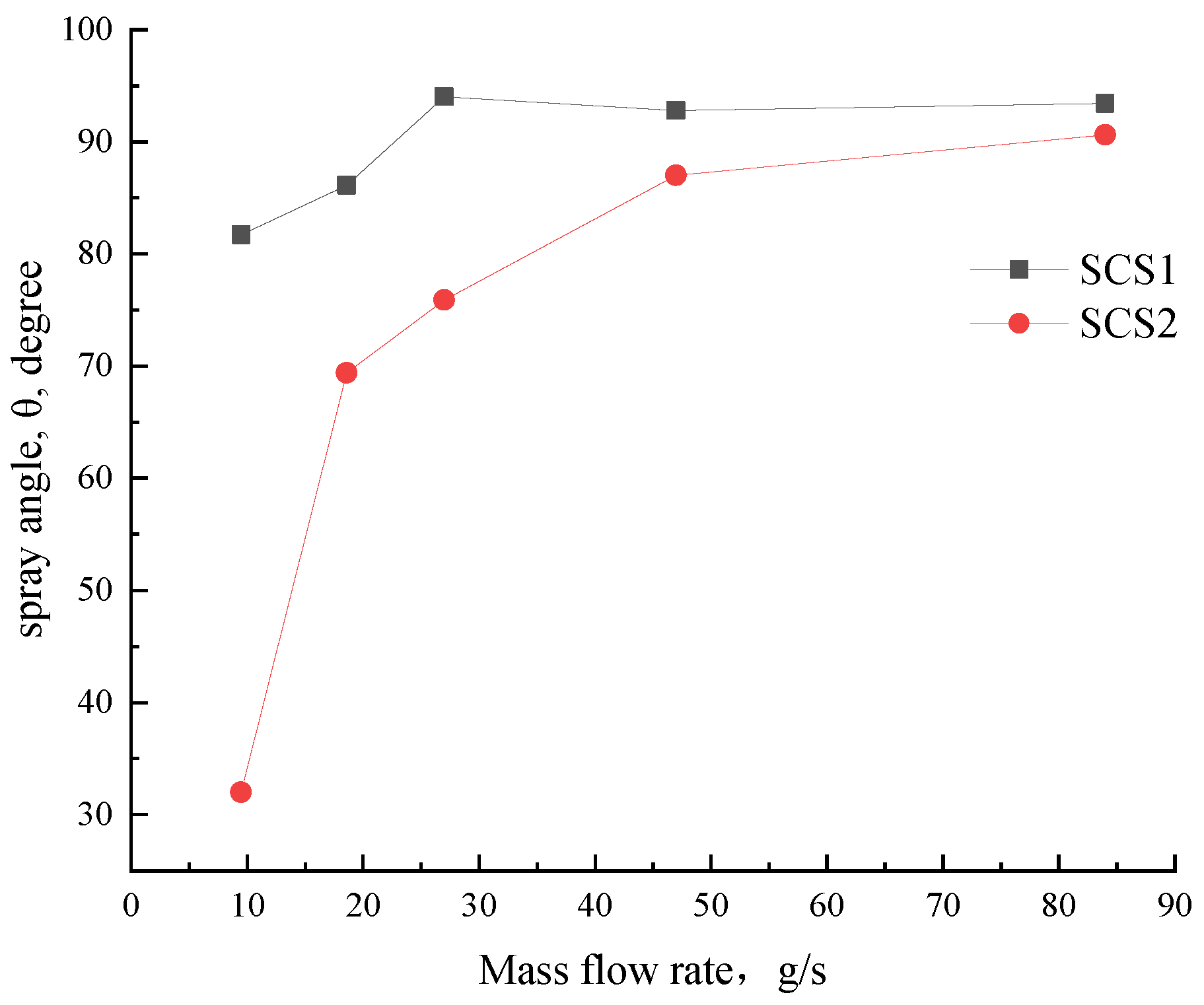
Figure 5. The atomization angle obtained in the working conditions, SCS1-1 and SCS1-2 (working conditions lower than the design point), is significantly lower than that of SCS1-3 (design point), while the flow rate is greater than the design point, the atomization angle did not change significantly. SCS2 also has the same trend. Since the working condition SCS2-1 deviates more from SCS2-4 (design point), the atomization angle also differs more. The atomization angle of the two injectors at their respective design points is not much different, slightly higher than the designed atomization angle (82°). From the analysis of the previous atomization process, SCS2 could not work normally under the condition of a small mass flow rate; hence, with the continuous increase in the flow, the working conditions for its normal work were established, and its spray cone angle also became stable. For the same injector, increasing the injector flow increased the injector pressure drop. With the increase in the pressure drop, the spray angle of the injector increased continuously, however, when it reached a certain extent, the influence of the pressure drop on the spray angle became unobvious.
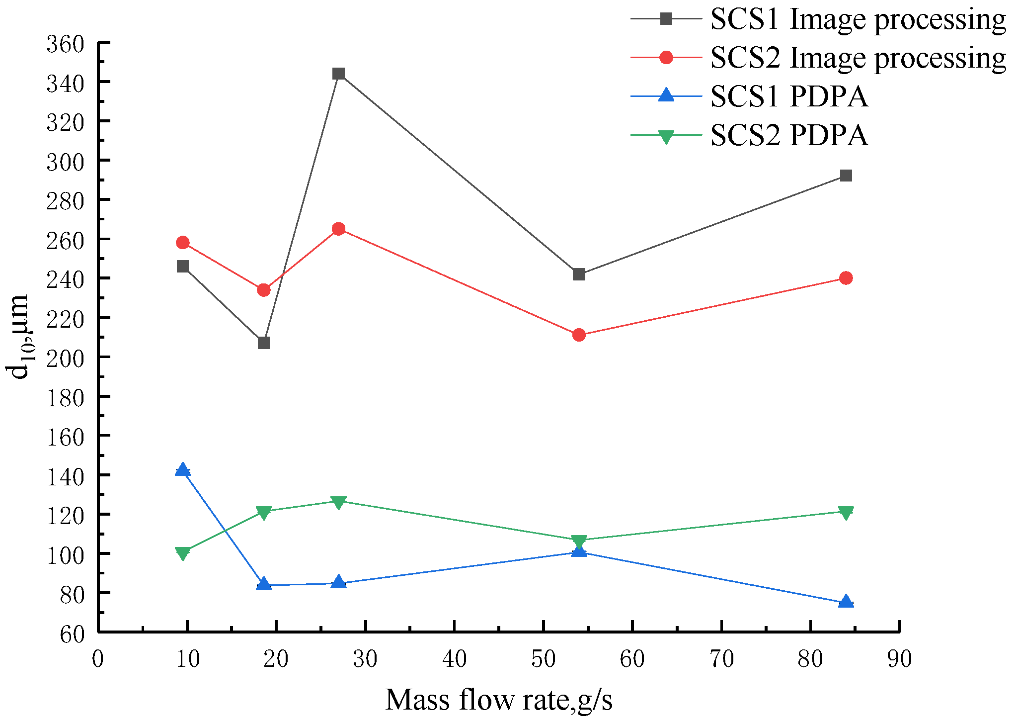
The average particle diameter of the atomization field was obtained by image processing to explain the influence of the mass flow rate on the atomization effect. The particle diameter is obtained by processing and analyzing a single image with the most exposed particles after filtering. The average diameter of atomized particles obtained by image processing is the average length, expressed by d10.
The average particle diameter of the steady-state atomization field in the cold flow experiment was also tested by the PDPA system. The PDPA system adopted single-point measurements and five tests were carried out at a distance of 20 mm from the injector in five working conditions of SCS1 (SCS1-1, SCS1-2, SCS1-3, SCS1-4, SCS1-5). Three tests were carried out at different distances (20 mm, 30 mm, 40 mm) of SCS1-1,
d32 and
d10 were obtained by analyzing the obtained particle information. Sauter diameter
d32 is generally used to express the particle diameter of liquid spray to characterize the atomization quality of the liquid spray. PDPA was used to show the Sauter mean diameter
d32 and average particle diameter
d10 for comparison with the image-processing results. The results of the average length diameters
d10 of the atomization field are shown in
Figure 6, and the Sauter mean diameters
d32 are presented in
Figure 7. Due to the relatively large error of the results obtained by image processing, only the error bars of the PDPA calculation results are provided. The PDPA device has a high accuracy of 0.5%. According to the experimental data, the measurement errors of
d10 and
d32 are both less than 1 µm, therefore the error bars in
Figure 6 and
Figure 7 are not obvious.
According to
Figure 6, the average length diameter showed poor regularity. The results obtained by the two methods exhibited great differences. Especially in the average diameter, the results by image processing were all over 200 µm, whereas those by PDPA were all below 150 µm. The difference was mainly related to the data-testing and processing methods of the two test methods. The image-processing method took shooting the entire atomization as the data source of particle diameter processing. In the average diameter processing, the method first detected the particles in the entire image, then calculated the particle diameters and number, and finally obtained the average length diameter. The difference in ambient lighting conditions would also affect the image-processing results.
PDPA adopted the single-point test, recorded the number of particles passing through this point, and generated the average. Image processing represented the average of particles in the entire atomization field, whereas PDPA was the average of a point in the atomization field for an entire period of time. For the steady-state atomization field, the particle diameters at a certain point were basically close, whereas those in the entire atomization field were different. The points tested by PDPA were basically in the secondary atomization area of the atomization field; thus, the obtained particles had small diameters. The images obtained by photography also suffered the influences of large particles. Large particles would shield small ones. As a result, few small particles were collected as samples. Therefore, the average particle diameter by image processing would be large.
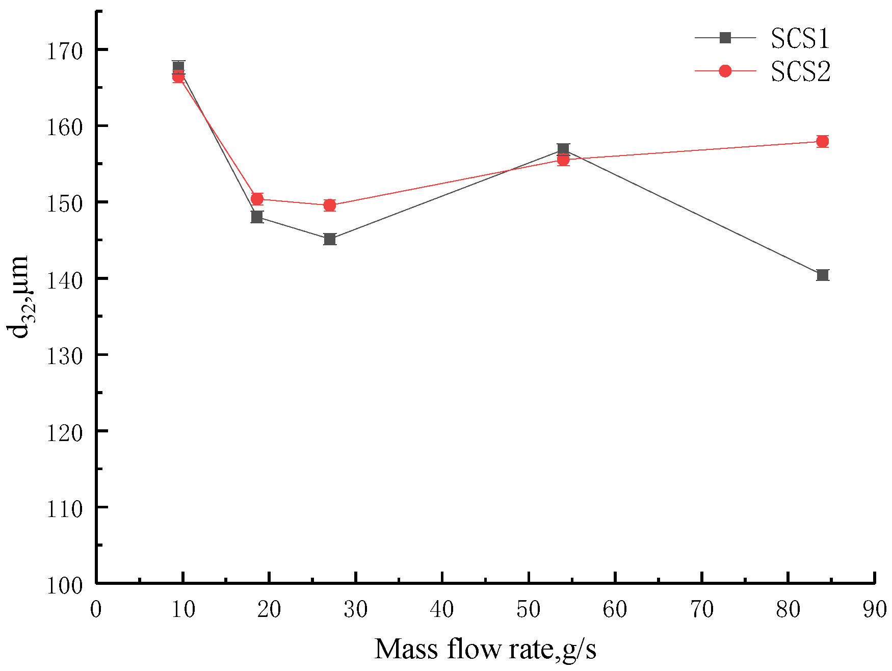
In
Figure 7, with the increase in mass flow, the
d32 of SCS1 continued to decrease while the
d32 of SCS2 decreased first and then leveled off. Under the same flow condition, the average particle diameter of SCS2 was larger than that of SCS1. Their average diameters were both below 170 µm. This result showed that within the same 280 flow range, the injector with a larger mass flow rate and smaller pressure drop as the design point had large atomized particle diameters. Under the same flow condition, the pressure drop of SCS2 was smaller than that of SCS1. Therefore, increasing the pressure drop could reduce the atomized particle diameter, which was beneficial for atomization. The injector with a larger mass flow rate and smaller pressure drop as the design point could reduce the pressure drop within the mass flow rate range; however, it would reduce certain atomization performance. It can also be seen from the image-processing results that steady-state atomization is established faster in the case of larger flow, and the particles in the image are more uniformly distributed. According to the results of this study, a working condition slightly lower than the median value of the flow rate range can be selected as the design point and the selected pressure drop can be slightly higher. This choice avoids the situation that the minimum working condition deviates too much from the design point and cannot be atomized. However, an excessive pressure drop will lead to excessive flow velocity, which may cause cavitation and reduce the flow coefficient. This requires a higher design level of the injector. Excessive pressure drop can also increase the supply pressure in the supply system, which can result in increased structural mass. In the design of variable-flow working injectors, the pressure drop requirement and atomization effect should be considered to ensure that the injector has a good atomization effect in the acceptable pressure drop range.
The particle diameters of the atomization field at different axial positions were tested for the steady atomization field of SCS1-1 to explain the characteristics of the atomization field. The test was conducted at the places 20, 30, and 40 mm away from the injector exit in the atomization field. The average particle diameters
d32 of liquid spray obtained in the test are shown in
Table 7.
From
Table 7, when the injector mass flow rate was constant, the atomized particle diameter decreased along the axial direction of the injector, which meant the atomization effect became obvious. The relative difference in the atomized particle diameters also became small, which meant the atomization tended to be in a steady-state. Thus, the selected test area was basically in the secondary atomization area, and the injector could achieve good atomization in a short distance.
In this research, the scheme of comparing the mean diameter by image processing at different positions from the injector with the corresponding data obtained with PDPA has been considered. However, this scheme has the following difficulties that lead us to abandon it. The specific difficulties are as follows: (1) After the image obtained by the high-speed camera is processed by grayscale and binarization, the particles in the center of the atomization area are connected together and cannot be captured, and only a few particles on the edge can be collected. This results in that there may not be exactly every particle that can be captured at every position from the injector, and even if there are individual particles at the desired position, there will be too few samples to have a statistical explanation significance. (2) It is highly subjective to obtain particles at specific positions by adjusting the contrast and brightness. In this way, only the atomization quality of different working conditions can be evaluated; however, the atomization quality of different positions of the same working condition cannot be evaluated.
3.3. Discussion of the Measurement Method
For the PDPA technology, it can obtain the particle diameter accurately at a certain position from the injector. However, it could not capture the evolution of the entire atomization field and could not obtain some atomization characteristic information, such as the atomization angle.
For high-speed photography technology, it can help us obtain information intuitively, such as the evolution processes of the atomization field and the atomization angle. However, the diameter of particles measured by high-speed photography is quite different from that measured by the PDPA method. The reasons for the error are as follows:
(1) High-speed photography compresses the three-dimensional atomization field into two-dimensional pictures, which causes the particles to be connected together and the particles in different spaces then appear on the same plane. It is difficult to obtain effective information on the particle size in the central area, which can only be detected by particles scattered from the edge. Under the steady-state atomization, the number of particles that can be obtained from different photos varies greatly, so we tried to choose the picture with the most particle exposure after filtering and calculating the particle size by circle detection.
(2) In order to expose more particles in a designated position, it is necessary to adjust the brightness and contrast, and this process cannot rule out human subjectivity.
It is precisely because of the above reasons that the particle size information obtained by the high-speed photography method is very different from that obtained by the PDPA method, which also proves the superiority of the PDPA method in measuring particle size.
Table 8 demonstrates some binary images and circle detection results that we chose in our image processing, showing that only edge particles can be captured:
4. Conclusions
This study evaluated the atomization characteristics of two screw conveyor swirl injectors under different mass flow rates and obtained the influence of the injector mass flow rate on the atomization process, spray angle, and average particle diameter. The injector flow exerted a great influence on the atomization process and form. The influence became obvious below the design point. Below the design point, the spray angle increased with the mass flow rate; above the design point, the mass flow rate presented a small influence on the spray angle. With the increase in the mass flow rate, the Sauter diameter of the atomization field continued to decrease. Under the fixed-flow condition, the farther it was from the injector exit in the atomization field, the smaller the Sauter diameter was. For the variable-flow working injector, the selection of design points considerably influenced the working range and performance of the injector.
Two methods of high-speed-photography-combined image processing and PDPA were adopted in this study to process the average diameter of the atomization field. The average particle diameter obtained by the former was greater than that by the latter due to the difference between the two methods in the selected processing domain. The current image-processing method cannot accurately reflect the atomization effect of the injectors. In this regard, we have added several suggestions for future scholars to improve this method: (1) Before the formal experiment, perform a short-term injection and focus calibration of the droplets. (2) Focus the camera field of view on a small region to increase the image resolution. (3) Multiple cameras can be used to shoot from different positions in the circumferential direction, and the obtained particle size results can be averaged. (4) Some substances that help to reflect light can be added to the cold flow medium so that the particles can be photographed more clearly.


