1. Introduction
In recent years, the use of unmanned aerial vehicles (UAVs) around the globe has steadily increased due to their inherent advantages compared to manned alternatives, such as the low operating cost, increased endurance and, most notably, their ability to operate under hazardous conditions. Additionally, the demand and availability of UAV systems has also seen a dramatic increase, mainly because of their reduced purchase cost and the advanced autopilot systems that allow novice operators/pilots to operate them successfully. Currently, the market value of UAV-related applications is estimated at over USD 127 billion, with UAV sales between 2016 and 2021 seeing a growth rate of 7.6%, and over 100,000 new jobs are expected to be created by 2025 [
1]. The different UAV designs vary, from small hand-launched UAVs weighing under 1 kg, to high-altitude long-endurance (HALE) systems of several tons. The systems are currently used in a wide range of missions, from security and border monitoring, to precision farming and photogrammetry.
One of the main targets for future UAV designs is to improve their flight endurance. In the case of small electrically powered UAVs, the research is focused on battery technology, aiming to achieve an increased capacity and a reduced weight [
1]. Larger tactical, or MALE UAVs, are mainly powered by an internal combustion engine, which has limited optimization prospects in terms of engine efficiency. The majority of these UAV designs are based on the tube-and-wing configuration, with a large number of exposed parts (e.g., cameras and landing gear), while the so-far-adopted UAV design strategies mainly focus on data-link capabilities, autopilot functionality and safety aspects, with aerodynamic performance having been overlooked until recently [
2]. The overall UAV design strategy can be enhanced with design methodologies that also aim to reduce the weight, optimize the aerodynamic layout or improve the performance of these configurations [
3].
Since UAV layouts are not expected to change dramatically and some limitations regarding exposed parts cannot be overcome, it is necessary to investigate technologies and strategies that result in performance enhancement for current designs. In this context, passive flow control techniques that reduce the overall drag of an aerial vehicle seem appealing. An example of such a technology that is already implemented on commercial airliners is the natural laminar flow airfoils used on the main wings of aircrafts in order to delay the boundary layer transition to the turbulent regime and, thus, reduce the skin friction drag component.
For the regions of the flow where the boundary layer is turbulent, the use of the passive flow control technique based on the usage of riblets can provide an additional skin friction reduction. The riblets are microgroove geometries, with sizes in the range of a few hundred μm depending on the flow friction velocity. The riblets interact with the small scale vortical structures in the near wall region and alter the flow inside the boundary layer, with three distinct mechanisms; consequently, leading to the reduction in skin friction [
4]. More specifically, riblets (a) elevate upwards the cross-flow motion in their crests and displace streamwise vortices and streaks away from the wall, (b) weaken the near-wall turbulence regeneration cycle and (c) dampen the spanwise flow fluctuations [
5].
In recent decades, a significant amount of research has been performed focusing on the riblets’ geometry and size, in applications where aerodynamic drag reduction is needed. Early experiments on flat plates showed that by using mainly V-shaped riblets, a maximum total drag reduction of 8–10% could be achieved [
6,
7,
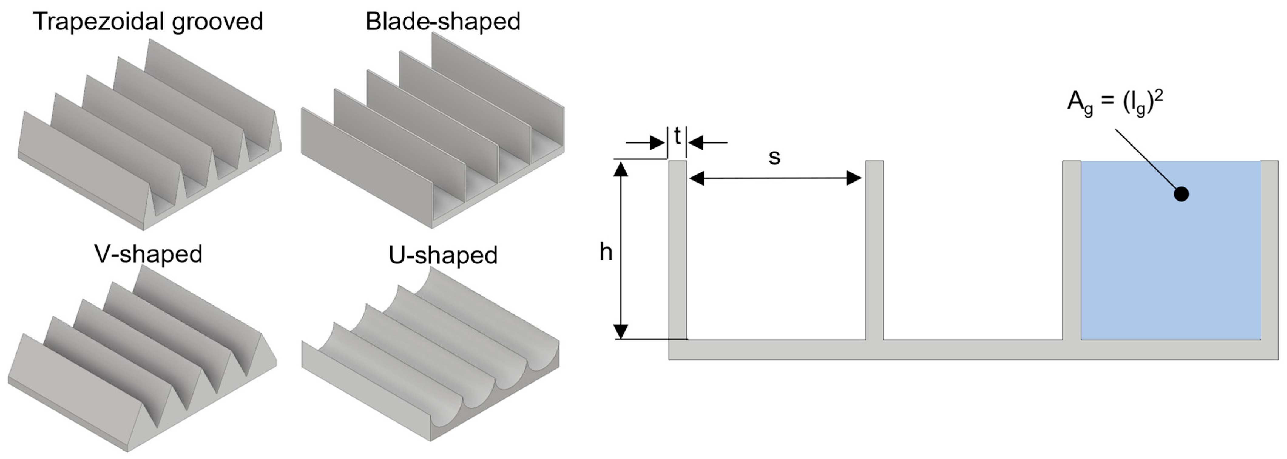
8]. In several other studies, various riblet geometries, such as sinusoidal, U-shaped, blade-shaped and trapezoidal grooved riblets (
Figure 1), were investigated and showed the aforementioned percentage of drag reduction. From the available literature, it can be concluded that blade-shaped riblets provide the optimum performance in terms of the aerodynamic drag reduction, though they are prone to damage and are difficult to fabricate. Bechert et al. [
9] carried out extensive oil channel experiments on blade-shaped and trapezoidal grooved riblets, and concluded that the latter, though inferior in terms of efficiency, was overall the best compromise between actual performance and practical application in engineering aerodynamic problems.
To correlate the relationship between the drag reduction effect of riblets and the Reynolds number, Walsh and Linderman [
6] first used the non-dimensional riblet spacing, expressed in wall units
, where
s is the riblet spacing,
u* is the friction velocity and
is the kinematic viscosity, with the optimal riblet size corresponding to a relatively constant value of
for a large number of riblet geometries and sizes. Based on the experimental results of Bechert et al. [
10], for triangular, trapezoidal, blade and scalloped riblets, Garcia-Mayoral and Jimenez [
4] showed that for different types of riblets, the optimum value of the non-dimensional square root of the groove cross section
had a smaller variation compared to
and, thus, was more representative of the riblets performance.
In the past, research focused on the application of riblets in commercial airliners, where the viscous drag component can be as high as 50% of the aircraft’s total drag [
11], and their benefit can be correlated to significant savings in fuel costs. As the number of globally operating UAVs is increasing, the interest in the effect of riblets for these applications also increases, since the issues related to riblet applicability are relatively easier to solve. This is due to the fact that the areas covered by riblets are orders of magnitude smaller compared to commercial airliners, while their benefits remain significant [
3]. In both cases, several additional parameters influence the performance of riblets compared to a flat plate case, because the boundary layer developing on the surface of aircraft wings is affected by adverse and favorable streamwise pressure gradients, as well as three dimensional effects and spanwise gradients due to sweep. There have been experimental investigations on the influence of the pressure gradient [
11,
12,
13] and sweep angle on the performance of riblets [
14]. In a concise manner, Viswanath [
11] presented many results of earlier works in that area and concluded that the viscous drag reduction in airfoils at zero and low incidence is comparable to that of a zero-pressure gradient flow over a flat plate. Results from the application of riblets on actual aircraft, such as the main wing of a T-33 [
15] and, more recently, the fuselage of a JAXA experimental aircraft [
16], were very encouraging, as shown by the measurements performed in experimental wind tunnels.
Additionally, the similar passive flow control technique of vortex generators (VGs) has been investigated and implemented on various aircrafts [
17,
18]. The VGs are generally small thin geometrical structures that are mainly used for lift enhancement and separation control. Conventional VGs have a height of roughly the same order of magnitude as the airfoil’s boundary layer thickness (
), while low-profile VGs have a height between 10–50% of
and have demonstrated enhanced performance [
17]. The latter are even more similar to the riblet geometries in terms of dimensions, and experiments have shown that they can provide a drag decrease, though this is mainly associated with separation control [
17,
19]. Their main disadvantage is that their exact placement is highly critical compared to conventional VGs and must be reasonably close upstream from the expected separation location. These VGs create streamwise vortices in the near-wall region, and are capable of overcoming separation but dissipate further downstream when the flow attachment is achieved; thus, enhancing their performance. Depending on the type of flow separation that is expected, counter-rotating VGs are ideal for mitigating 2D flow separation, such as in the case of a low-sweep aircraft wing, while co-rotating VGs are mainly used for 3D flow separation (duct inlets and high-sweep wings). The use of VGs though not providing any significant benefit in low angles of attack (AoA) where no flow separation is expected, could be used synergistically with riblets, so the aerial vehicle’s performance is improved during take-off and landing, as well as the cruise and loiter phases.
From the computational point of view, several researchers have simulated riblets using high-fidelity techniques such as large eddy simulations (LES) [
20,
21] and direct numerical simulations (DNS) [
22]. Due to the high computational cost, a short range of cases has been investigated, limited to flows around a simple flat plate or airfoil geometries, corresponding to Reynolds numbers around 180 for flat plates based on the friction velocity and 180,000 for airfoils based on the freestream velocity. This range of Reynolds numbers is at least one order of magnitude smaller than the ones corresponding to currently operational UAVs or other practical applications. These two factors combined, prohibit the use of such high-fidelity techniques for most industrial applications and, hence, they are primarily used for fundamental studies of the physics involved in the flow development in areas close to the surface, where riblets are installed as flow controllers, and to acquire a better understanding of the mechanisms that result in the overall drag reduction [
4].
In the present work, the potential benefit from the use of riblets is investigated on a medium-altitude long-endurance (MALE) UAV, in terms of the aerodynamic performance and fuel consumption reduction and, thus, the endurance and payload capability increase. The existence of the riblets on solid surfaces (e.g., wings and fuselage surfaces) is modelled using an appropriate boundary condition on the less computationally expensive CFD modeling approaches with the adoption of the RANS equations approach. This boundary condition is specifically designed for application on the k-ω family turbulence models, by altering the value of the specific turbulence dissipation rate ω at the wall, mimicking the existence of riblets and their impact on flow development.
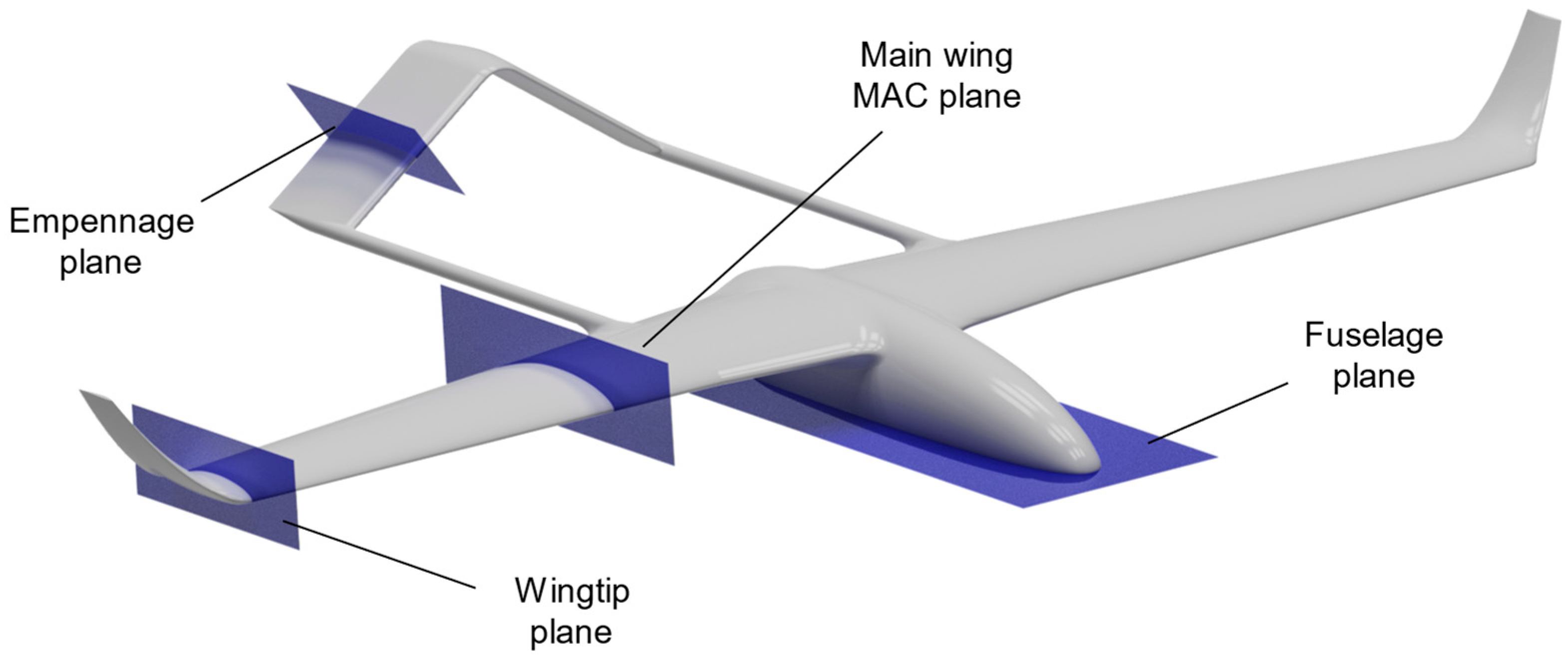
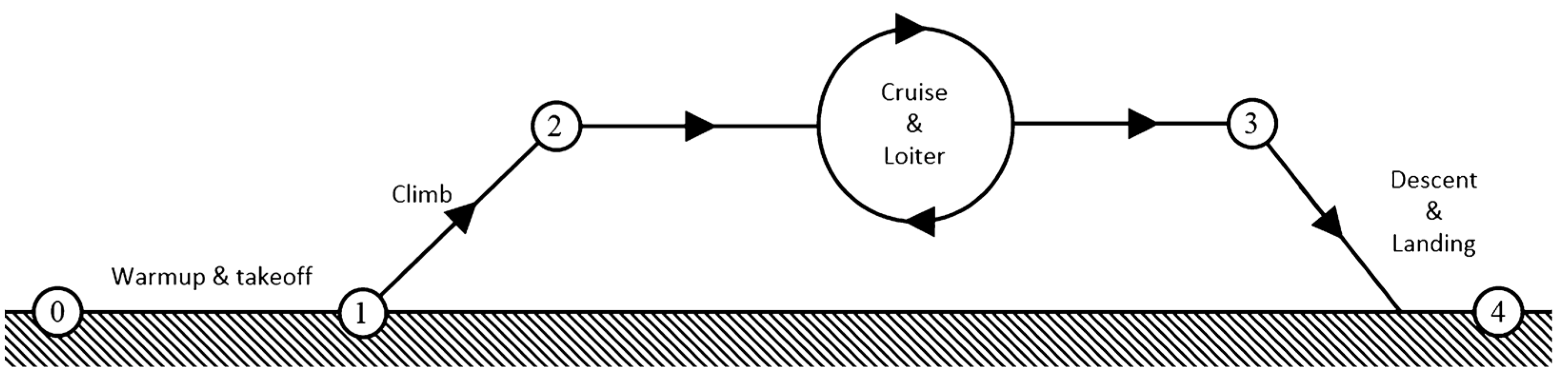
The overall benefit of the riblets is examined for three specific areas of application on the external surface of the UAV (i.e., main wing, empennage and fuselage) and for the most critical flight segments of a typical mission profile.
3. Results and Discussion
Initially, the contribution of each of the three areas covered with riblets was examined. In loiter conditions, the riblets were applied both separately on the main wing, fuselage and empennage, as well as simultaneously on all three areas, as described in
Section 2.3, and were assessed for their contribution to the overall drag reduction on the UAV compared to the case with no riblets using Equation (8).
The results presented in
Table 4 refer to loiter conditions at a 0° AoA and indicated that the riblets applied on the fuselage had the greatest drag-reducing effect, while those on the empennage had the least. The lift and drag coefficients presented in
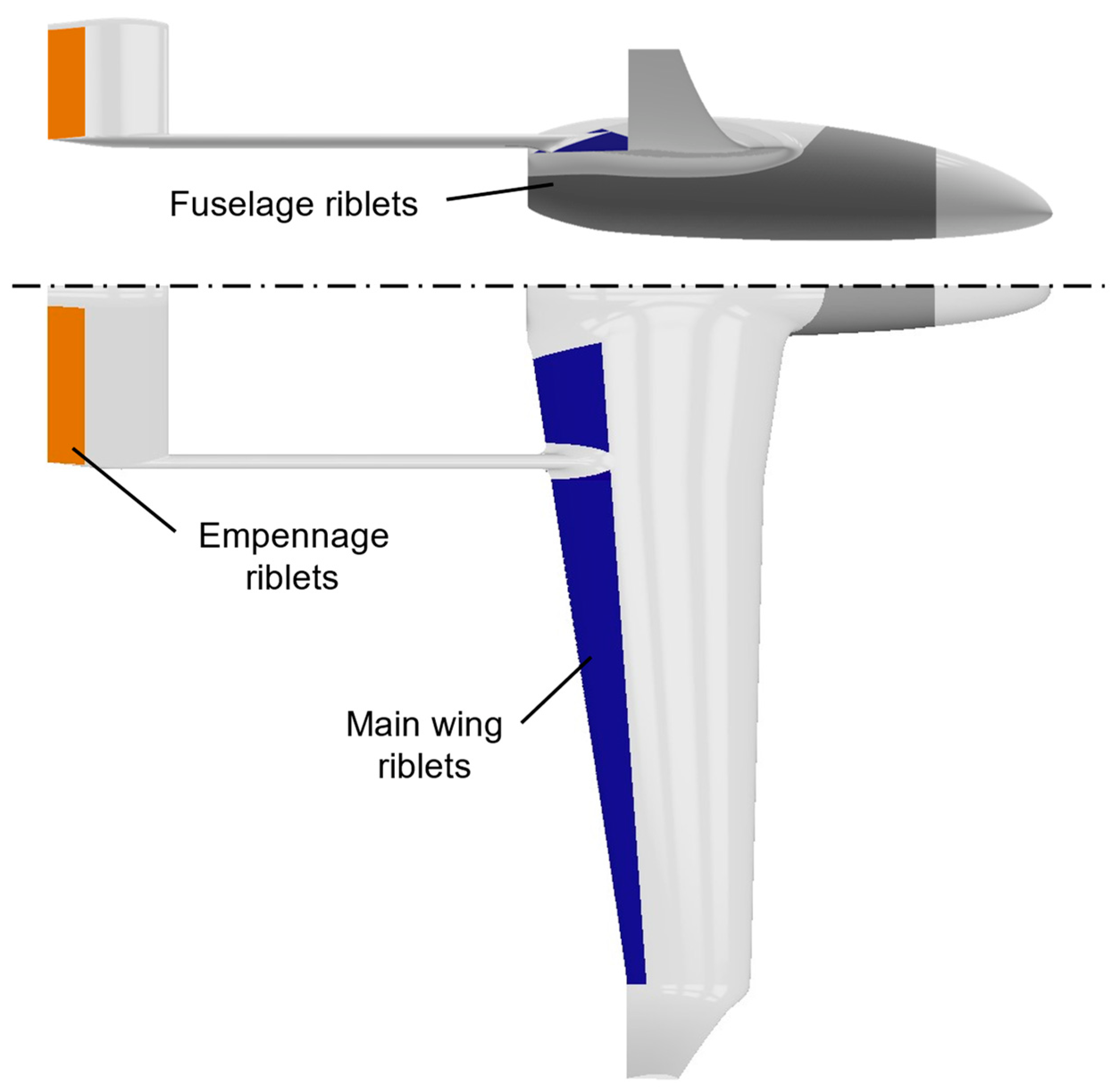
Table 4 refer to the whole aircraft and not each individual component. More specifically, due to the larger riblet-covered area on the fuselage (
Figure 10) compared to the other two surfaces, the aerodynamic drag reduction benefits were noticeable. Riblets influenced both the skin friction and pressure distributions on the surfaces they were applied to; hence, they also had a small positive effect on the produced lift [
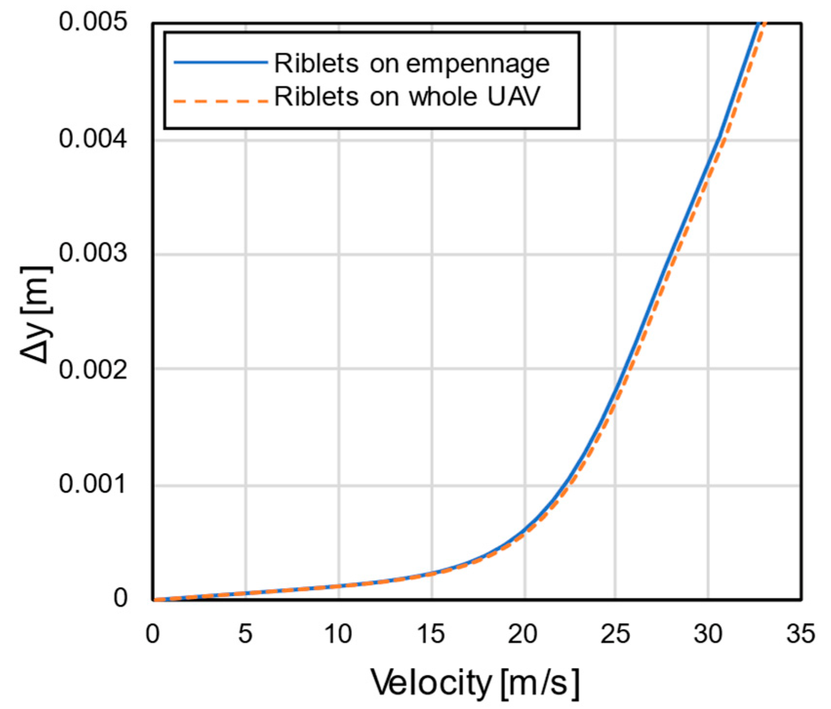
34]. Most importantly, it was observed that the drag reduction benefit from the simultaneous application of riblets on all three area of the UAV was somewhat lesser than the corresponding sum of drag reduction if the riblets were applied on the three surfaces separately. This indicated that the presence of riblets on one area of the UAV altered the flow field, mainly the velocity field and turbulence generation due to riblet presence, in a way that affected the downstream UAV parts where riblets were applied and their performance was reduced. All three areas were interlinked, but the greatest interference existed between the riblets applied on the front part of the UAV (fuselage and main wing) and the empennage, because the flowfield alteration from the first was propagated downstream and reduced the performance of the latter. In
Figure 11, the velocity profiles on the empennage plane at the
position are presented. The cases examined refer to riblets applied only on the empennage and on the whole UAV, respectively. The observed small difference between the two was indicative of the downstream propagated interference and riblet performance degradation.
Additionally, it must also be noted that the small increase in CL due to riblets did not result in any significant increase in induced drag; therefore, it did not reduce the actual riblet performance.
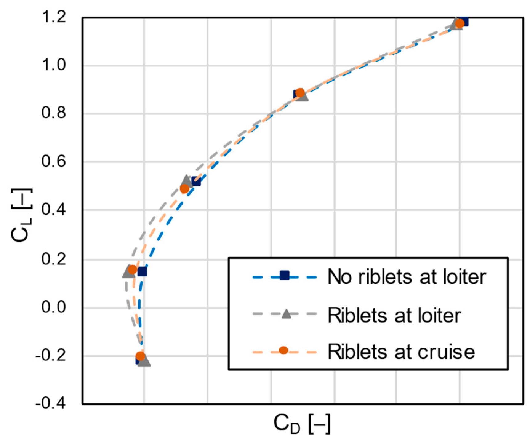
To investigate the benefit of riblets on the overall loiter phase, a series of CFD computations was performed, with and without riblets in a range of angles of attack between −8° and 8°, within which the UAV nominally operates during a typical mission. Additionally, the effect of riblets during cruise was also investigated for the same range of angles of attack. The results of the computations were presented in the form of drag polars in
Figure 12, with the riblets offering a 4.8% total drag reduction at their design point (i.e., loiter conditions at 0° AoA). For the loiter phase, in the off-design points of higher AoA, the drag reduction due to the riblets quickly diminished to around 0.5% at 4° and became negligible at 8°. In negative AoA, there was initially a drag reduction comparable to 0°, up until the minimum value of
, from which point forward it quickly became a drag increase as the angles decreased further. The ±8° AoA cases examined were mostly presented in order to demonstrate the high degradation of riblet performance that resulted from the AoA variation. Additionally, they indicated that the use of poorly designed riblets or riblets designed for very different flight conditions could also possibly result in a drag penalty. Moreover, since the riblets were designed for the loiter conditions (
), the cruise conditions (
were considered an off-design point for all angles of attack. The results showed a similar behavior as in the loiter cases, though the overall riblet effectiveness was reduced in the whole AoA range. Based on these results, the poorer performance of riblets in the case of cruise conditions resulted in a separate drag polar curve.
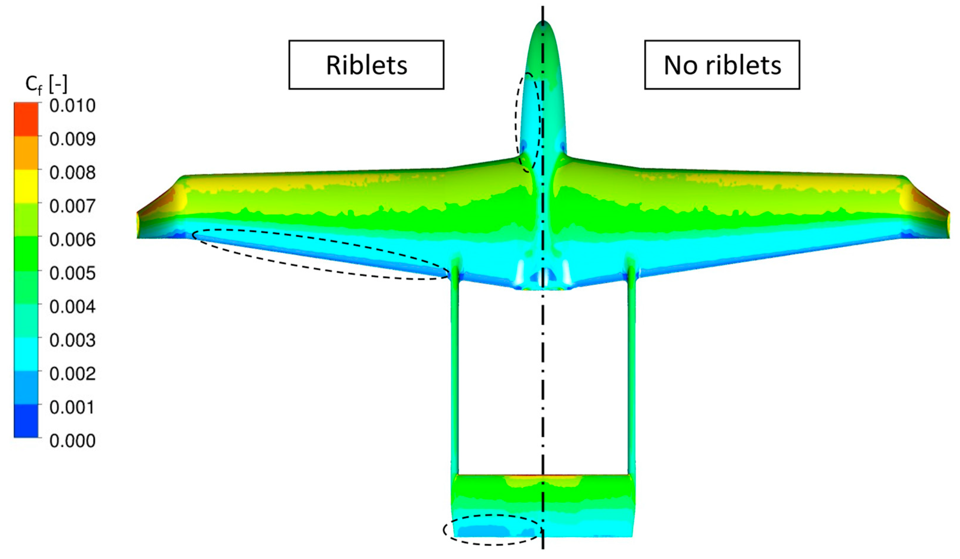
In
Figure 13, the skin friction coefficient on the surface of the UAV was presented for the cases with and without the applied riblets. It was observed that skin friction reduction was present in all the areas where riblets were applied (i.e., main wing, fuselage and empennage). The increased effect of riblets could be seen clearly on the front side of the fuselage and the rear side of the empennage, where the skin friction reduction was obvious (in the order of 12–15%). Regarding the main wing, the skin friction reduction was observable near the trailing edge, where the area of lower skin friction (deep blue color) was increased.
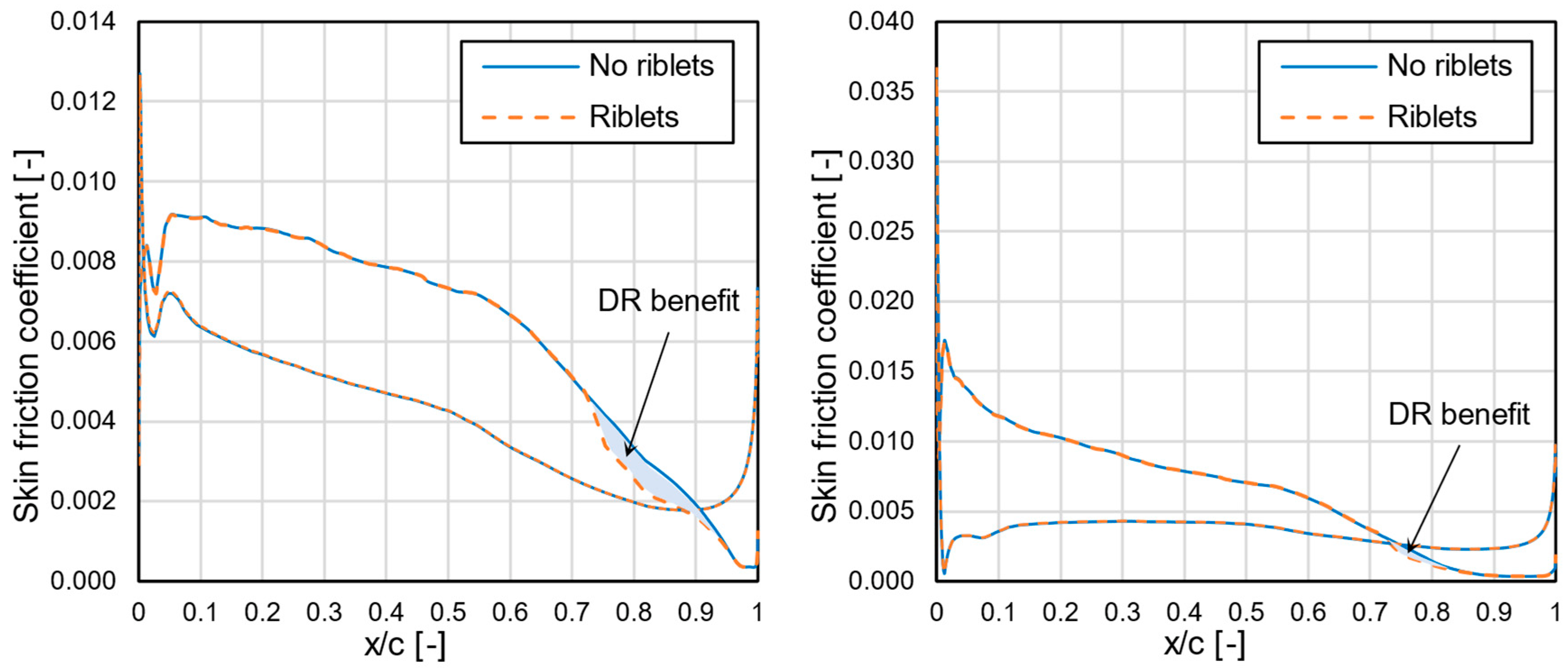
The effect of riblet application on the main wing was presented more clearly in
Figure 14, where the skin friction coefficient on the mean aerodynamic chord of the main wing was plotted for the 0° and 8° AoA at loiter conditions. The riblets reduced the skin friction in the region between
and the trailing edge of the airfoil, though the skin friction reduction was not equally distributed. The greater part of skin friction reduction was located in the area close to the initial riblet application point (i.e.,
) and diminished towards the trailing edge. This unequal skin friction distribution was even more evident at the 8° AoA (
Figure 14 Right), where only a small part of the riblet application area offered a drag reducing effect. In the work of Bliamis et al. [
35], the same procedure for riblet implementation using an ω boundary condition was applied on an NACA0012 airfoil for a constant
value on the whole airfoil. Comparing these results with
Figure 14, the highly unequal distribution in the reduction in skin friction (roughly between
and
) observed in the present case could be attributed to the use of a constant riblet size over the whole main wing. The specific riblet characteristics in this work were selected based on the mean wall shear stress value of each application area (main wing, empennage and fuselage). Since the wall shear stress varies along an airfoil, the riblets were not expected to operate optimally at all locations of each given area. Therefore, it was expected that the benefit from the installation of riblets on the UAV’s surfaces could be increased if the surfaces where they were applied were broken down to smaller areas and a larger number of riblet sizes was used to ensure that a greater part of them operated in the optimal conditions at a given time.
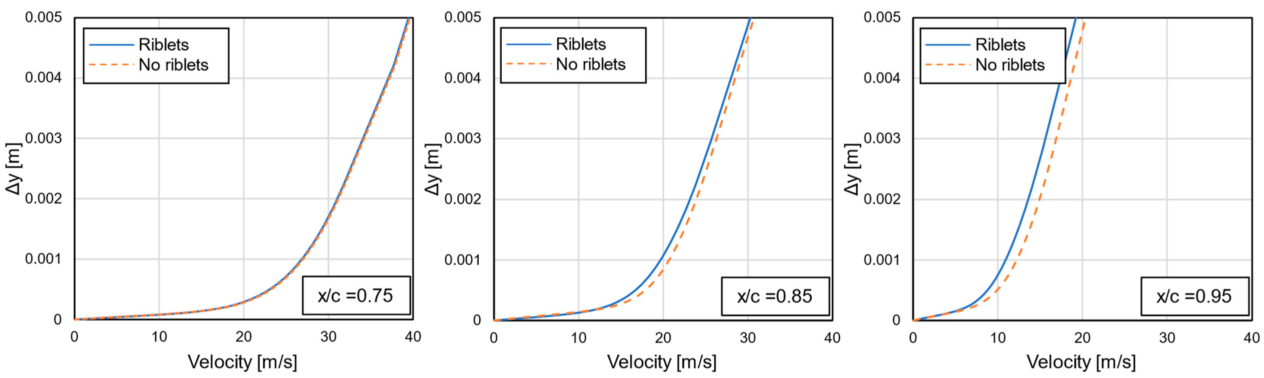
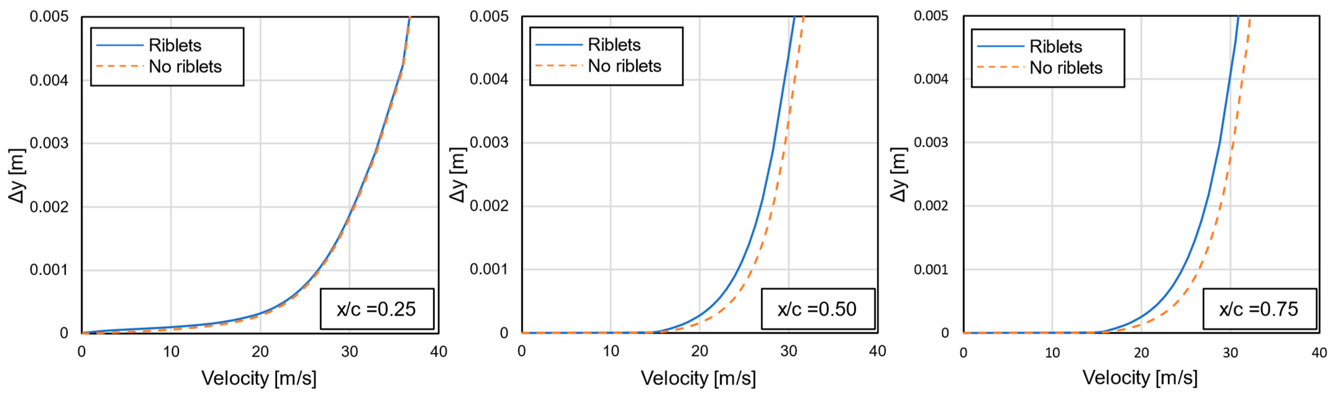
In
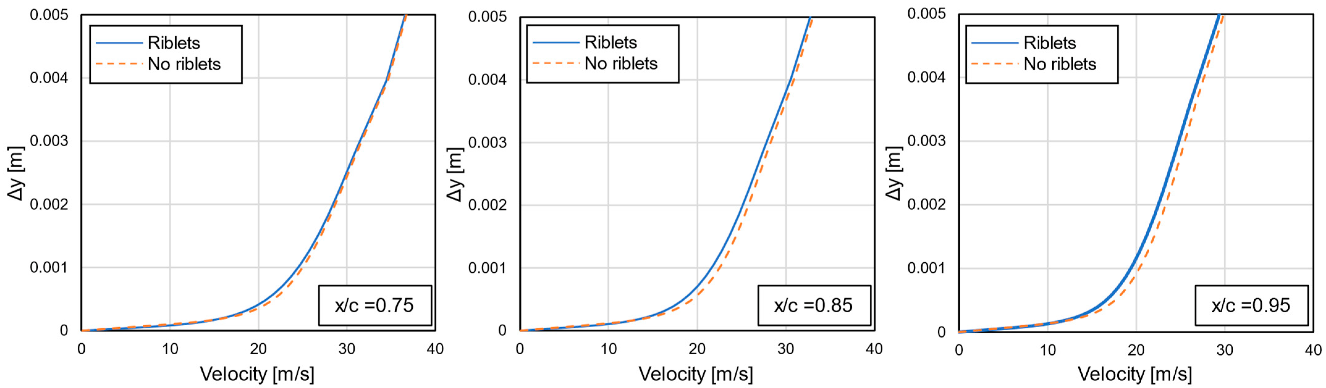
Figure 15,
Figure 16 and
Figure 17, the velocity profiles on the MAC, fuselage and empennage planes are presented for different positions along the longitudinal axis, at design conditions (loiter at 0° AoA). These positions covered the whole extent of the area in which riblets were applied. In all three planes, it was observed that the effect of riblets was small near the start of the riblet areas (left diagrams) and became greater downstream. The results presented in these figures agreed with the previously determined observations (
Figure 14) and, thus, supported the conclusion that the benefit from riblet use could be improved with a further breakdown of each individual area of application into smaller ones.
Regarding the effect of riblets on the performance of the UAV, the endurance for the loiter phase was examined, since the latter constituted the largest segment of its mission. Typically, the endurance of a propeller-driven aerial vehicle could be calculated using Equation (9). To achieve the maximum endurance time, the aerial vehicle needs to operate at the maximum C
L3/2/C
D value. In this form of the endurance equation, the loiter velocity was removed from the equation and a constant flight altitude was assumed [
36].
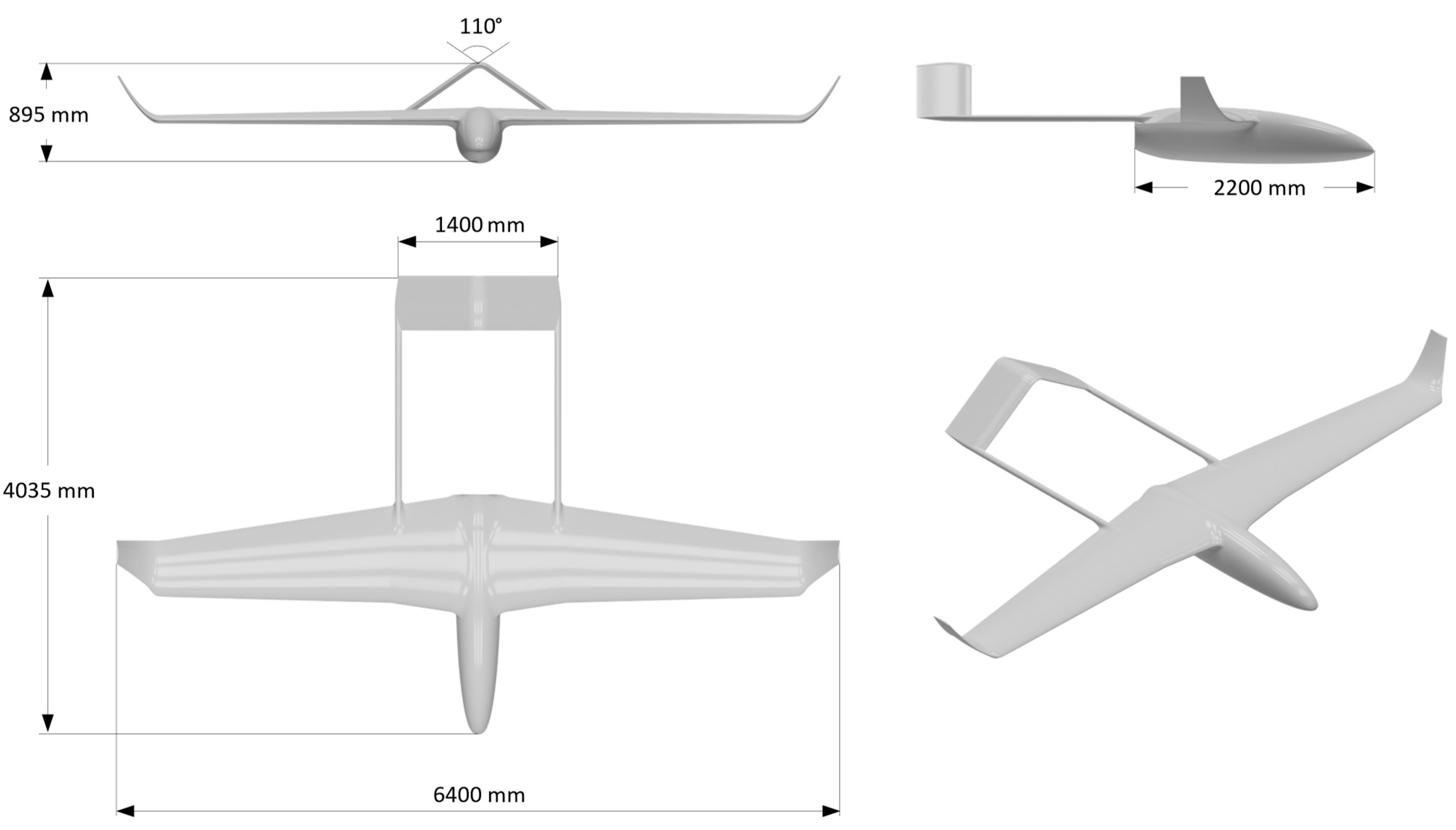
In the present work, the HCUAV RX-1 performed its loiter segment with a predefined fixed velocity value (
). In this case, the endurance equation could be written in the form of Equation (10), where the UAV’s loiter velocity was introduced as a variable [
36,
37].
where the
Wi and
Wf are the UAV’s weight at the start and end of the loiter phase, respectively,
Cbhp is for the engine brake horsepower,
np is the propeller efficiency,
is the air density at the loitering altitude,
is the UAV’s reference area and
(
and
are the lift and drag forces (coefficients) of the UAV in the loiter segment. Two different scenarios were examined, on both of which the gross take-off weight (GTOW) of the UAV was kept constant. Regarding the benefit in endurance, the fraction of the UAV’s weight during loiter in Equation (10) was held constant (i.e., the same amount of fuel was burned); hence, only the lift-to-drag-ratio was increased. This resulted in an endurance increase of 7% (about 45 min). The second scenario examined the potential payload weight increase for the initially specified endurance (i.e., the reduction in fuel requirement was directly translated into a payload increase). This could result in a 5% payload weight increase (about 2 kg) for an endurance of 11 h. The results of the two scenarios are summed up in
Table 5.


