Article

A Beam Search-Based Channel Allocation Method for Interference Mitigation of NGSO Satellites with Multi-Beam Antennas

1
School of Aerospace Engineering, Tsinghua University, Beijing 100084, China
2
Qian Xuesen Laboratory of Space Technology, China Academy of Space Technology, Beijing 100094, China
*
Author to whom correspondence should be addressed.
Aerospace 2022, 9(4), 177; https://doi.org/10.3390/aerospace9040177
Submission received: 28 February 2022 / Revised: 18 March 2022 / Accepted: 19 March 2022 / Published: 23 March 2022
(This article belongs to the Special Issue Recent Advances in Spacecraft Dynamics and Control)

Abstract

:
In the past few years, non-geostationary orbit (NGSO) satellite communication constellations have regained popularity due to their conspicuous advantages. Nevertheless, with more NGSO satellites getting involved in communications, the spectrum resources should become much more scarce. Multi-beam high throughput satellite and spectrum sharing are two major techniques in communication design. The two techniques can significantly mitigate interference and highly augment the capacity of the communication system. Thus, they are commonly used in satellite communication systems nowadays. With a massive number of NGSO satellites comprising the communication system and moving in their orbits, interference scenarios are pretty complex. In this article, the relationship between the level of interference and the beam distance is deduced. Moreover, for beams with different tilting angles, the different off-axis angles may correspond to the same beam distance, which is directly related to the interference level. Through the interference analysis, we propose a channel allocation method that uses a beam search algorithm to optimize the channel allocation problem and achieves outstanding time efficiency. The performance of the proposed method is validated by a coexisting scenario of the geostationary orbit and NGSO satellite communication systems. The results show that the level of interference can be largely mitigated, and the capacity of communication systems is significantly augmented.

1. Introduction

Recent years have witnessed the sharp development in related concepts of satellite internet constellations [1,2] deployed in low Earth orbit (LEO). The constellations aim at providing internet access anywhere on the globe [3], hoping to solve the problems that nearly 3 billion people in the world cannot connect to the internet [4] and over 70 percent of global geographic areas remain uncovered by the internet [5]. Satellite internet constellations have a distinctive characteristic of providing worldwide seamless coverage. Therefore they are currently becoming one of the fundamental technologies for the Internet of Things and the technical foundation of 6G [6,7,8].
In the past few years, with the geostationary orbit (GSO) becoming much more crowded and the great reduction in expense for manufacturing and launching satellites [9], non-geostationary orbit (NGSO) satellite constellations have attracted significant attention from the industry once again. Some globally-known high-tech companies such as SpaceX [10,11], OneWeb [12,13], Telesat, Amazon, and Boeing are making efforts to lay out and construct the NGSO satellite internet constellations working in Ku/Ka, or even Q/V bands. Compared with the tentative version with tens of satellites in the early 1990s [14] (Iridium, Globalstar, etc.), due to the low cost of manufacturing and launching, the NGSO constellations now designed are typically made up of thousands of satellites. With deeper worldwide participation in the exploration of the application of NGSO communication satellites, it is predicted that, by the year 2029, there will be nearly 57,000 satellites orbiting in low Earth orbit, over 80 percent of which will belong to the USA.
Compared with traditional GSO satellites used for communication, large NGSO satellite communication constellations possess four competitive edges. The first is global seamless coverage areas [15]. It is not suitable to traditionally build the internet for most spaces on the land, on the ocean, and in the sky, whereas the satellite communication systems can achieve seamless coverage easily. The second is low transmission latency [16]: for many commercial customers, there exists a long transmission delay when the information is transmitted worldwide. The transmission speed through optical fiber cable is two-thirds that of light in vacuum, thus tens of milliseconds of time delay can be avoided by transmission from satellites above. The third is low expense: compared with constructing communication infrastructure for 5G stations and undersea optical fiber cable, reusable launching rockets that can send tens of satellites into space at once and low-priced satellite manufacturing costs embody apparent advantages. The last is Broadbanding [17]: technologies such as utilization of high frequency and frequency reuse allow higher communication capacity. Nevertheless, with the coexistence of multiple GSO and NGSO satellite communication systems, more and more sophisticated potential interference would occur. To ensure the quality of service of different systems, interference analysis and avoidance have become crucial in the construction of NGSO satellite communication systems.
Rapid augmentation of NGSO communication satellites makes the requirement for spectrum resources utilized by them rather urgent. As a consequence, countries around the world are positively studying NGSO satellite communication technologies to take a share in spectrum resources. After all, by the end of this decade, the communication spectrum and orbit resources will have become much scarcer than ever before [18]. In this context, according to certain rules, researchers have put forward many solutions. High throughput satellite (HTS) is currently one of the research highlights in satellite communication to improve spectrum efficiency, which is formerly put forward by American consulting company Northern Sky Research. In comparison with traditional communication satellites, the HTS is equipped with multi-beam antennas which would significantly improve the total capacity of satellites with identical spectrum resources. Other than that, spectrum sharing is currently recognized as one of the crucial technologies to enhance the utilization efficiency of frequency bands. However, it probably results in co-frequency interference between different communication systems [19]. According to the suggestions put forward by the International Telecommunication Union (ITU), the terrestrial and GSO satellite communication systems possess priority over the NGSO satellite systems in the utilization of spectrum resources. Thus, from the perspective of interference, the already-built terrestrial and GSO satellite communication systems and the NGSO satellite systems can be regarded as primary and secondary systems, respectively. The primary system can use spectrum resources without any constraint, while the secondary system ought to use them without significant effect on the primary system in cases in which the same spectrum resources are utilized.
GSO satellites have a relatively long history of being utilized for communication. The almost complete analysis of interference scenarios between them has been constructed to achieve interference mitigation. By contrast, the position and velocity of NGSO satellites constantly change, so the interference variables change with time and space, bringing about new challenges for the design of NGSO satellite constellations. In order to mitigate the co-frequency interference that results from NGSO satellite constellations, the ITU has carried out studies in advance about related techniques and proposed a series of mitigation strategies in its recommendations. The traditionally used methods include spatial isolation, time isolation, and so on. There are many published academic papers focusing on the mitigation of interference and elevation of performance in various communication systems by now. Nelson et al. [20] provided basic orbital and interference theories between the satellite systems in NGSO. Wang et al. [21] offered a spectrum sharing optimization method in the constellation design for NGSO broadband satellite systems. Lin et al. [22] proposed a fast calculation method based on the occurrence probability of satellite in the visible zoom. Portillo et al. [23] offered a comparison of the architecture of three large constellations of satellites in NGSO and provided methods to determine the number of ground stations and gateways and to estimate the total system throughput. Xia et al. [24] compared the beam coverage design of the OneWeb system with the SpaceX system and evaluated the performance of both systems. Li et al. [25] provided an adaptive beam power control method to mitigate the interference between multi-beam GSO and NGSO communication systems. Shen et al. [26] focused on the fractional programming theory and applied it to design the communication systems so as to obtain the maximum transmission data rate. Liu et al. [27] presented a dynamic channel allocation (CA) method based on deep reinforcement learning in multi-beam satellite systems which can effectively lower the blocking probability. Sharma et al. [28] proposed a novel cognitive beamhopping satellite system in spectrum coexistence of multi-beam satellites. Ren at al. [29] offered a modified Q-learning method based on a greedy algorithm for NGSO networks to lift the performance in spectrum-sharing scenarios with GSO and terrestrial networks. Wang et al. [30,31] provided a spectrum sharing method for cognitive GSO and NGSO satellite networks based on dynamic frequency allocation. The NGSO beams were divided into several clusters based on a seven-beam frequency reuse pattern, and the allocation scheme was implemented in each cluster.
The current work aims to develop a channel allocation method to mitigate the co-frequency interference involved with the NGSO satellites equipped with multi-beam antennas. There are two main contributions in this paper. Firstly, the mathematical relationship between the off-axis angle and beam distance is derived. For different beams in the satellites with multi-beam antennas, the same distance may stand for different off-axis angles with significantly different values. Therefore, the revised distance is introduced to reflect the off-axis angle better using beam distance. Secondly, a beam search algorithm is applied to obtain a rapid and robust solution for a coexistence scenario consisting of the NGSO and GSO satellites systems that can create a large number of beams.
The structure of this paper is organized as follows. The interference scenario, combined with interference evaluation index and antenna radiation patterns, interference parameters analysis, and the channel allocation method are presented in Section 2. In Section 3, a co-frequency compatibility simulation between the NGSO and GSO satellite communication systems is performed to verify the effectiveness of the channel allocation method, and then the simulation results are analyzed. In Section 4, the conclusions are deduced.

2. System Model of NGSO Satellites Equipped with Multi-Beam Antennas

2.1. Downlink Analysis Model

An interference scenario between two satellite communication systems with multi-beam antennas is illustrated in Figure 1. As the interference analysis of the uplink is quite similar to that of the downlink, here we take the downlink scenario as an example. For any satellite ground station or user terminal in the downlink scenarios, the signal intensity C that it receives from the corresponding satellite can be formulated as
C = P tw G tw θ 1 G r θ 2 4 π d w / λ 2
where P tw is the transmit power of the wanted satellite antenna, G tw · and G r · denote the gains of the wanted satellite antenna and ground station receiver, respectively, θ 1 and θ 2 are the off-axis angles between the main lobe axes and the lines of communication links, d w is the distance between the wanted satellite and the ground station, and the wavelength of carrier signal λ is related to the light speed c and frequency f by the relationship c = λ · f . In most common cases, the ground station always keeps pointing to its corresponding satellite so as to achieve the maximum gain of receiving antenna. Thus, θ 2 is usually set to zero when calculating the wanted signal intensity C. For any ground station on the Earth, it could receive signals that are sent from other satellites and carried in the identical frequency band rather than the wanted one. These signals would mainly contribute to the augmentation of the interference signal level. In Figure 1, let us assume that the interfered GSO ground station P is in the intersecting area of the coverage areas of the two beams. The downlink interference signal intensity I received by the ground station from a single interfering NGSO satellite antenna beam can be calculated as
I = F R P ti G ti θ ˜ 1 G r θ ˜ 2 4 π d i / λ 2
where F R is the frequency reuse factor, ranging from 0 to 1, depending on the carrier frequency the wanted and interfering satellites make use of. P ti is the transmit power of the interfering satellite antenna, G ti · is the gain of interfering satellite antenna, d i is the distance between the interfering satellite and the ground station, and θ ˜ 1 and θ ˜ 2 represent the off-axis angles. As shown in Figure 2, assuming that W 1 and W 2 are the frequency bandwidths used by the wanted and interfering systems, respectively, and that W overlap represents the overlap bandwidth between the two frequency bands, the frequency reuse factor can be expressed as
F R = W overlap W 2
Nevertheless, in reality, the interference origin can hardly be onefold. With a large number of communication satellites launched into free space, the interfering objects for ground stations are usually multiple. Additionally, plenty of NGSO satellites are equipped with multi-beam antennas. Taking these factors into consideration, for a GSO ground station, the interference signal it receives possibly originates from various NGSO satellites or various beams in a single satellite. It is therefore essential to take all these interference sources into account. The sum of all the interference I sum can be figured out as
I sum = M = 1 M sum N = 1 N sum I M N
where M sum and N sum are the numbers of interfering satellites and interfering beams in a satellite, respectively, and I M N stands for the augmentation interference the ground station receives from the Nth beam of the Mth satellite.

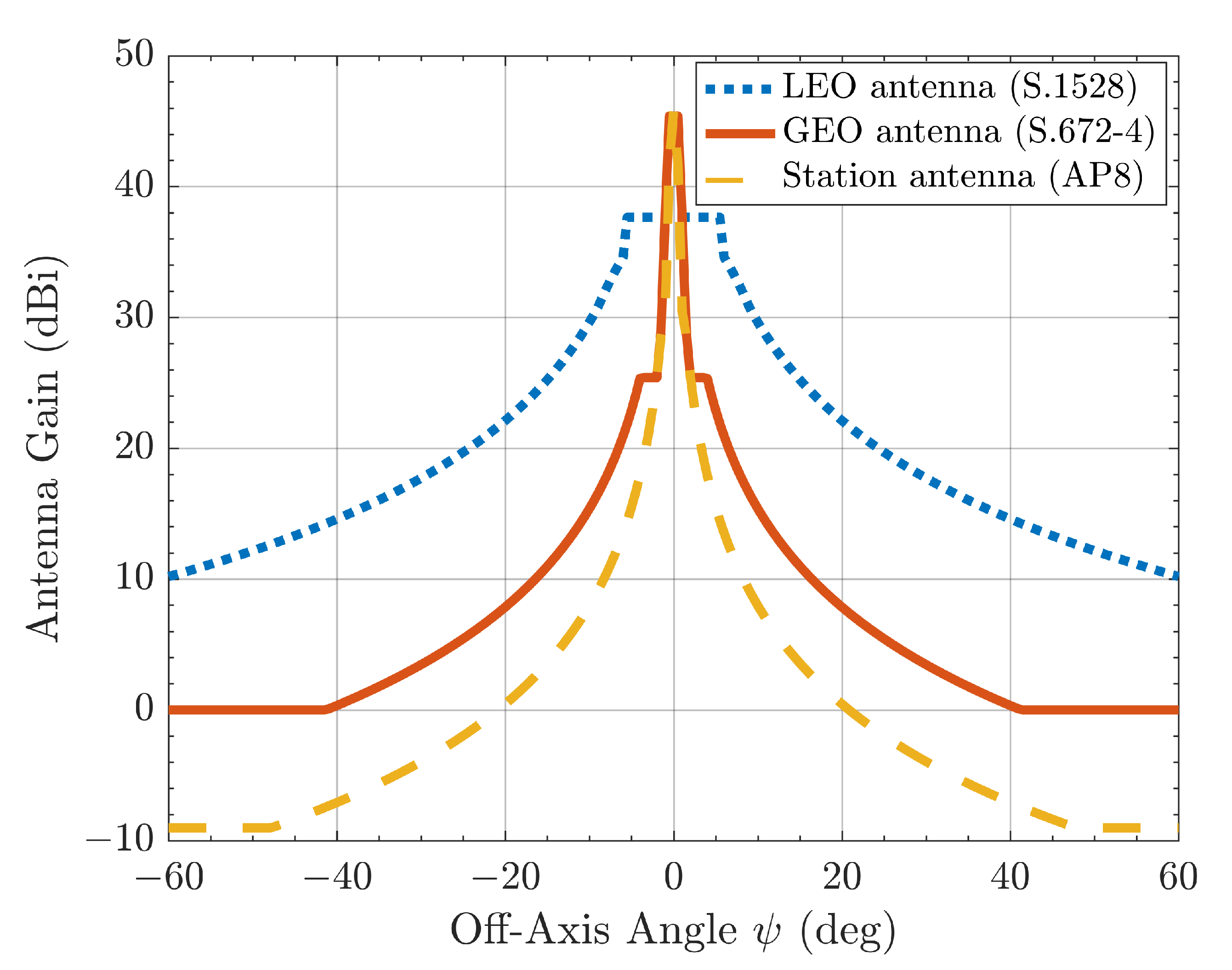
2.2. Interference Evaluation Index and Antenna Radiation Patterns

Interference evaluation indexes are utilized to indicate how seriously the target system is interfered by other systems. We choose to use different evaluation indexes in different situations. Commonly used indexes consist of the carrier to interference ratio C / I , interference to noise ratio I / N , signal to noise ratio SNR, and signal to interference plus noise ratio SINR, among other indexes. Based on the aforementioned equations, the four indexes can be calculated by the following equations.
C I = P tw G tw θ 1 G r θ 2 λ 1 / d w 2 F R P ti G ti θ ˜ 1 G r θ ˜ 2 λ 2 / d i 2
I N = F R P ti G ti θ ˜ 1 G r θ ˜ 2 κ T W λ 2 4 π d i 2
SNR = P tw G tw θ 1 G r θ 2 κ T W λ 1 4 π d w 2
SINR = P tw G tw θ 1 G r θ 2 λ 1 / 4 π d w 2 F R P ti G ti θ ˜ 1 G r θ ˜ 2 λ 2 / 4 π d i 2 + κ T W
where λ 1 and λ 2 are wavelengths of the wanted and interfering satellites, T is the receiver’s noise temperature, and κ and W represent the Boltzmann constant and communication link bandwidth, respectively. Here we choose SNR and SINR to illustrate how well our target systems perform with and without interference from other satellites. The index SINR signifies very clearly the system performance of a single link. As mentioned previously, the HTS is equipped with multi-beam antennas, which means multiple links are built in just one satellite. To take the performance of all the links into consideration and evaluate how much information a satellite can transmit, the capacity R are presented as follows on the basis of the SINR of each link. Supposing that Gaussian coding is adopted in the communication systems, the capacity R for the total number of links in a satellite can be calculated as
R = i = 1 N t W i · log 2 1 + SINR i
where N t is the total number of links in a satellite, and W i and SIN R i are the bandwidth and SINR of the ith link, respectively. This expression is a generalization of Shannon–Hartley theorem, and it provides the theoretical maximum for a link capacity.
Due to the keep-moving characteristic of the NGSO satellites, the off-axis angles of the transmitter and receiver vary continuously. We make use of the radiation patterns to obtain the gain of different antennas based on the off-axis angles at a specific time. The ITU has recommended several patterns for different scenarios. The radiation patterns described in the following are chosen for simulations in the later section. According to ITU-R S.1528 [32], the reference radiation pattern for low Earth orbit satellite antenna, whose antenna aperture diameter to wavelength ratio D / λ < 35 , is given by
G ψ = G m dBi 0 ψ < ψ b G m 3 ψ / ψ b 2 dBi ψ b ψ < Y G m + L s 25 log ψ / Y dBi Y ψ < Z L F dBi Z ψ < 180
where ψ is the off-axis angle, G m simplifies maximum gain in the main lobe, ψ b represents one half the 3 dB beamwidth in the plane of interest at the largest off-axis angle, L s is main beam and near-in side-lobe mask cross point below peak gain, L F is the far-out side-lobe level, equals to 0 for ideal patterns, and Y and Z are calculated by Y = ψ b ( L s / 3 ) and Z = Y · 10 0.04 G m + L s L F , respectively. Typically for a LEO satellite, L s = 6.75 and Y = 1.5 ψ b .
According to ITU-R S.672-4 [33], the reference radiation pattern suitable for GSO satellite antenna is given by
G ψ = G m dBi 0 ψ < ψ b G m 3 ψ / ψ b α dBi ψ b ψ < a ψ b G m + L N + 20 log ( z ) dBi a ψ b ψ < 0.5 b ψ b G m + L N dBi 0.5 b ψ b ψ < b ψ b X 25 log ( ψ ) dBi b ψ b ψ < Y L F dBi Y ψ 90
where L N , expressed in dB, is the near-in-side-lobe level relative to the peak gain required by the system design. z is the ratio of major axis to minor axis for the radiated beam, and the values of a, b, and α are determined by the value of L N . The ratio is 0 dB expectly, and in most cases it is devised not to exceed 3 dB. For L N = 20 dB and 25 dB , b is always 6.32 and α is always 2, and a is evaluated by 2.58 1 log ( z ) and 2.58 1 0.8 log ( z ) , respectively.
According to ITU-AP8-10 [34], the reference radiation pattern for the ground station antenna with antenna aperture diameter to wavelength ratio D / λ < 100 is given by
G ψ = G m 2.5 · 10 3 D / λ · ψ dBi 0 ψ < ψ m G 1 dBi ψ m ψ < ψ r 52 10 log ( D / λ ) 25 log ( ψ ) dBi ψ r ψ < ψ b 10 10 log ( D / λ ) dBi ψ b ψ 180
where G m , G 1 , and ψ m can be evaluated by equations G m = 20 log ( D / λ ) + 7.7 , G 1 = 2 + 15 log ( D / λ ) , and ψ m = 20 λ / D G m G 1 , respectively. ψ b is 48 , and ψ r = 100 λ / D for antenna parameters satisfying D / λ < 100 . The related parameters are listed in Table 1, and the relationship between the antenna gain and the off-axis angle are depicted in Figure 3. It is easy to see that when the absolute values of the off-axis angles increase, the antenna gains decrease rapidly. The gains remain unchanged when the off-axis angles are very large.

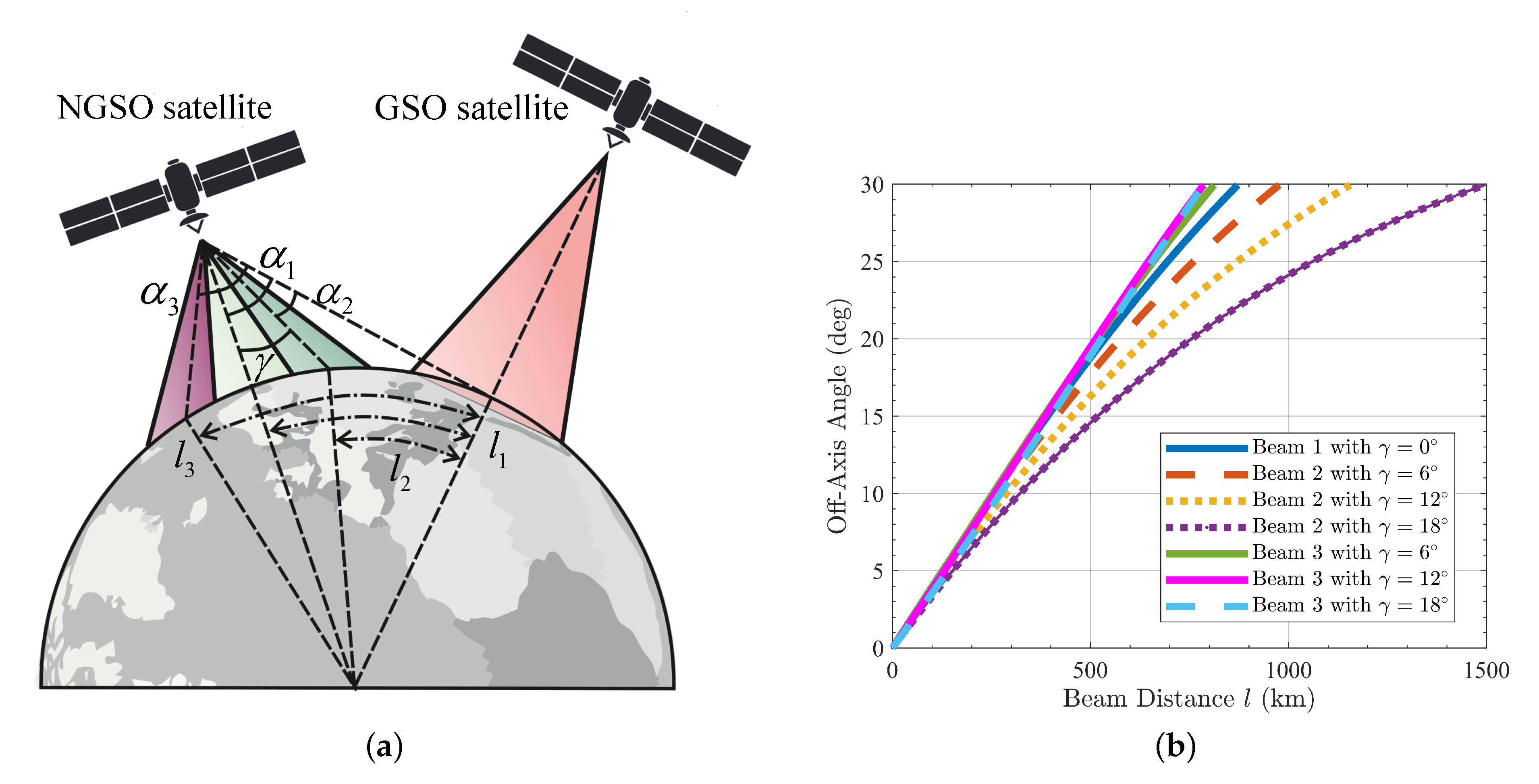
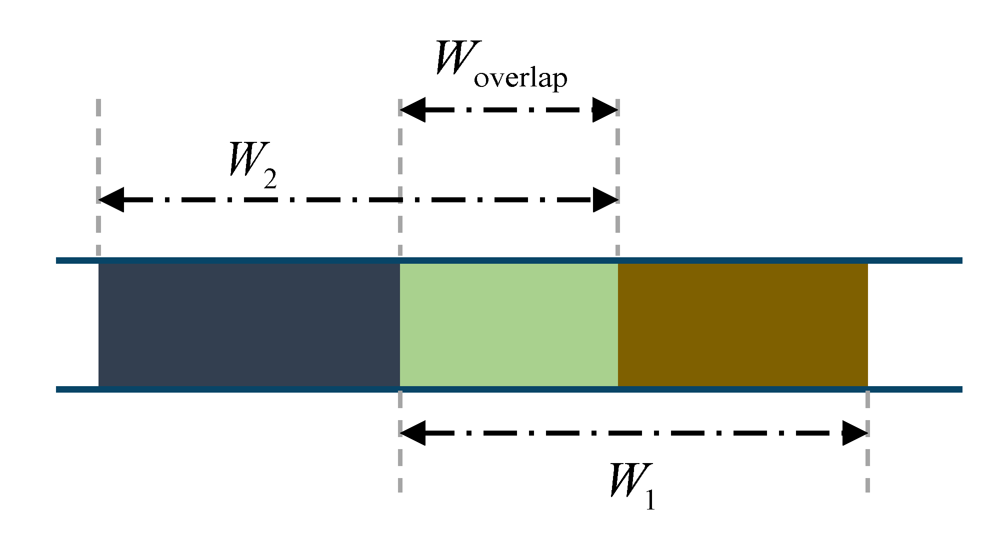
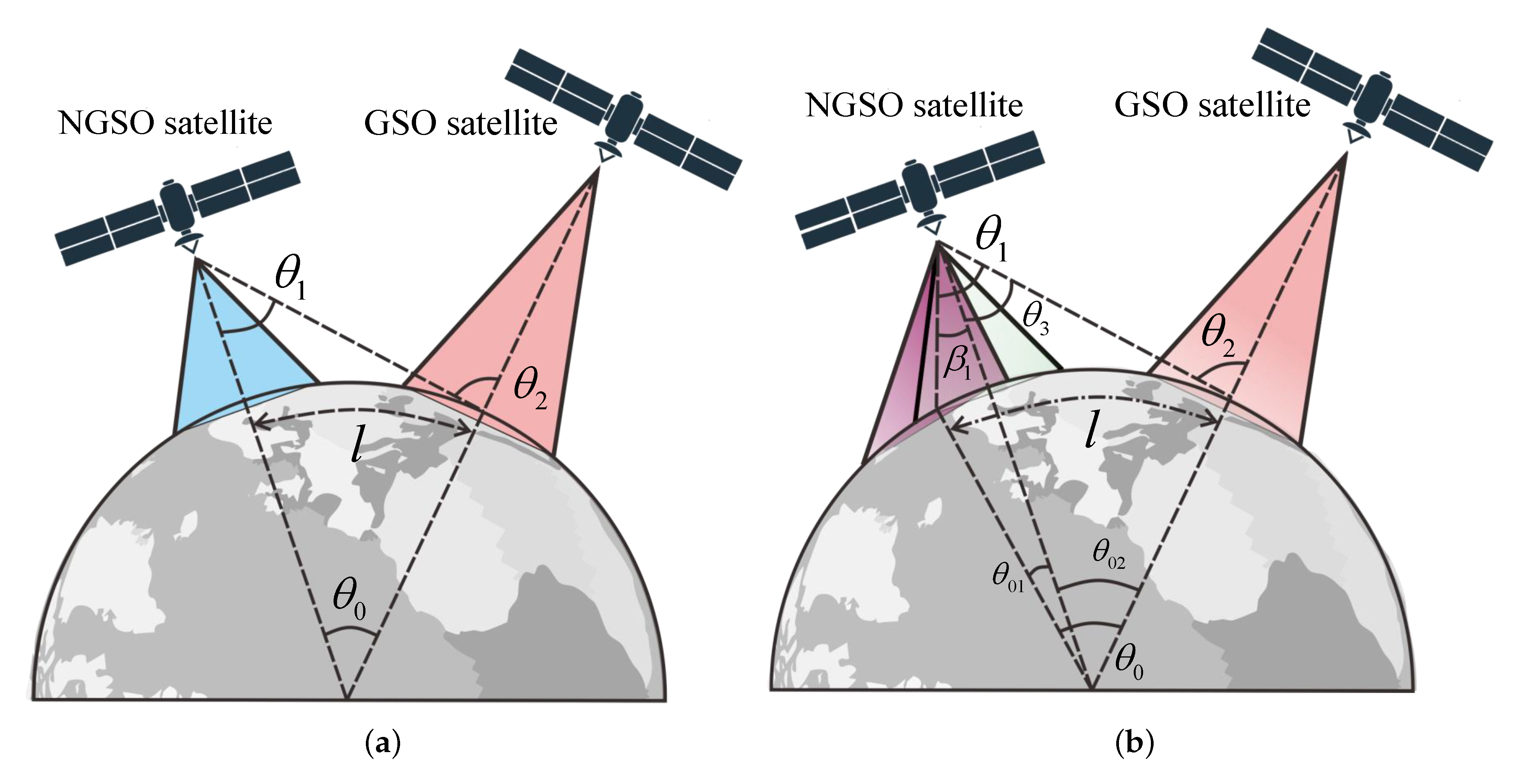
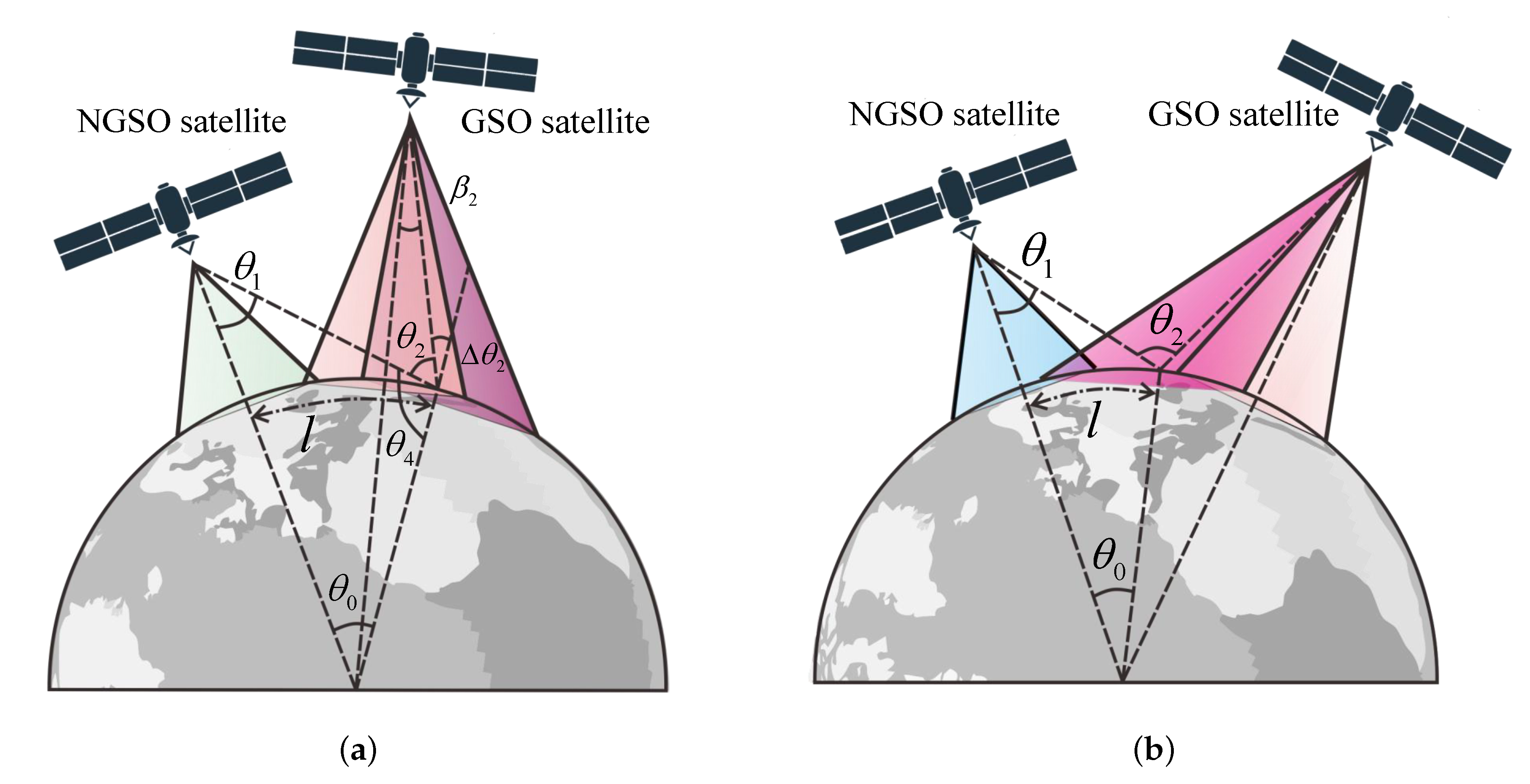
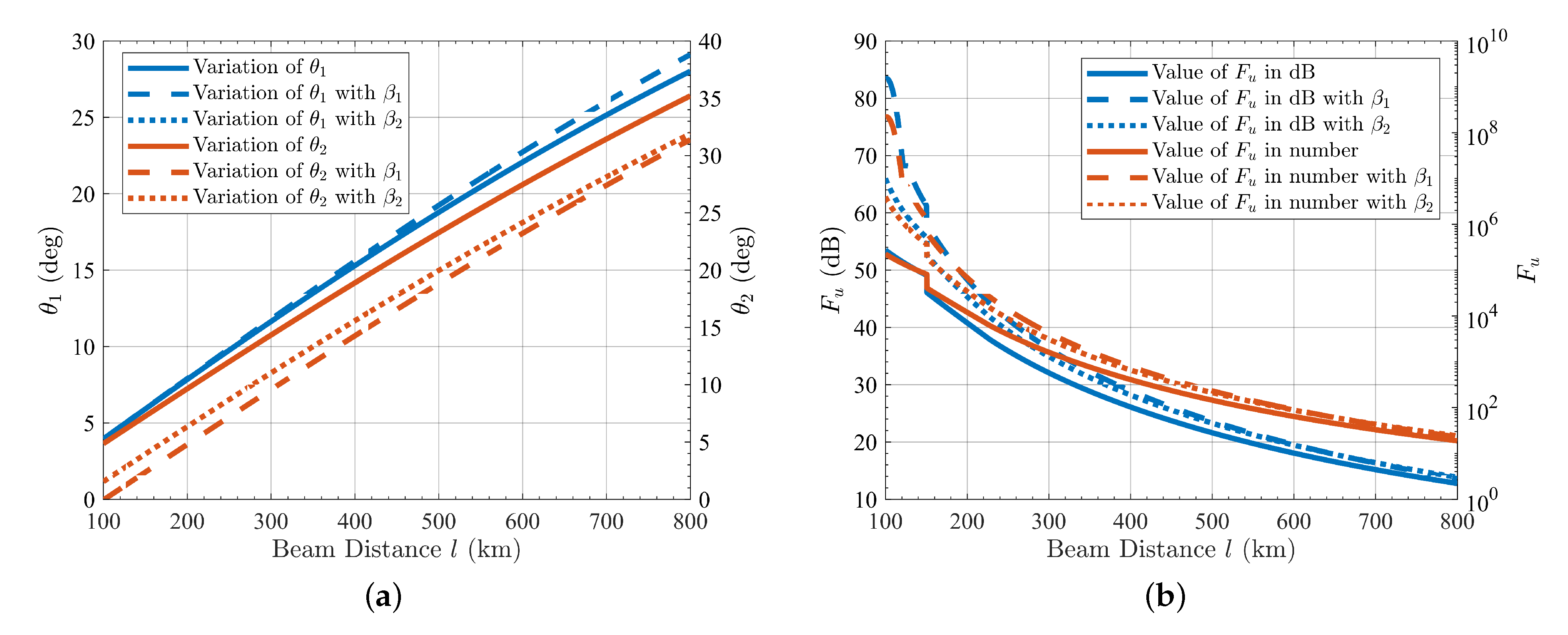
2.3. Analysis of Interference Based on Off-Axis Angle and Beam Distance

Here it is assumed that the interfered ground stations locate at the center of each beam of the corresponding communication satellite. Taking the GSO satellite communication system as an interfered instance, the illustrated scenarios are depicted in Figure 4 and Figure 5. According to the interference evaluation index given in Equation (8), the augmentation of interference I would result in the decline of SINR. To increase the SINR level of ground stations, it is apparent that the signal intensity from the interfering satellites should be as weak as possible, which means that two off-axis angles of the interfering link should be as large as possible. In addition, the off-axis angles θ 1 and θ 2 are closely related to the distance l between different beam centers as illustrated in Figure 4.
From Equation (2), one can find that the denominator depends only on the communication link distance d i . Considering the period of time when the NGSO satellite first approaches and then moves away from the GSO ground station, the variation of link distance Δ d i between the NGSO satellite and GSO ground station appear slightly different, which could be ignored compared with more significant variation of the off-axis angles between the satellite and ground station antennas. Therefore, theoretically, the variations of the link distance and off-axis angle are coupled, but the link distance has only a negligible influence on the interference I. Here, we assume that the path loss stays constant during the observation period. Let
F u = G ti θ 1 dBi + G r θ 2 dBi
This parameter largely represents the change of interference I. Let the distance between the beam centers of the NGSO and GSO be l. It should be noted that the distance l is measured over the surface of the Earth, and thereupon we obtain the geocentric angle θ 0 = l / R e . In the light of the law of cosines, the link distance between the NGSO satellite and GSO ground station can be calculated as
d i = R e 2 + ( R e + h ) 2 2 cos ( θ 0 ) R e R e + h
where R e is the Earth’s equatorial radius and h is the orbital altitude of interfering satellite. Then we find the off-axis angle θ 1
θ 1 = arcsin R e · sin ( θ 0 ) R e 2 + ( R e + h ) 2 2 cos ( θ 0 ) R e R e + h
Through the relationship θ 2 = θ 0 + θ 1 , the expression of θ 2 could be easily obtained
θ 2 = θ 0 + arcsin R e · sin ( θ 0 ) R e 2 + ( R e + h ) 2 2 cos ( θ 0 ) R e R e + h
The relationship between θ 1 , θ 2 , and beam distance l is depicted in Figure 6a. With the beam distance varying within the range [100, 800] km, the off-axis angles θ 1 and θ 2 increase monotonically and almost linearly with respect to the beam distance l.
Satellites equipped with multi-beam antennas have a unique characteristic that not all beams keep pointing to the nadir of the Earth, but they may have a certain beam tilting angle instead. Here, we carry on an analysis of the variables mentioned above in the situation where the NGSO and GSO satellite both have certain tilting angles. Figure 4b and Figure 5 show that θ 1 and θ 2 are solely influenced by the NGSO and GSO satellite antenna beam tilting angles β 1 and β 2 , respectively. For the case of the NGSO satellite antenna beam with a tilting angle β 1 which elongates the distance between the beam centers of the NGSO and GSO satellite antennas, we have the expressions of θ 01 and θ 02
θ 01 = arcsin R e + h R e · sin ( β 1 ) β 1
θ 02 = θ 0 + β 1 arcsin R e + h R e · sin ( β 1 )
Then one can easily obtain the expression of θ 3
θ 3 = arcsin R e · sin ( θ 02 ) R e 2 + ( R e + h ) 2 2 cos ( θ 02 ) · R e R e + h
So the angles θ 1 and θ 2 can be expressed as
θ 1 = arcsin R e · sin ( θ 02 ) R e 2 + ( R e + h ) 2 2 cos ( θ 02 ) · R e R e + h + β 1
θ 2 = arcsin R e · sin ( θ 02 ) R e 2 + ( R e + h ) 2 2 cos ( θ 02 ) · R e R e + h + θ 0 + β 1 arcsin R e + h R e · sin ( β 1 )
For the situation that the tilting angle of the NGSO satellite decreases the beam distance, by replacing β 1 with its corresponding negative number, one can obtain the corresponding expressions of θ 1 and θ 2 . As regards the calculation of θ 2 with tilting angle β 2 , we notice that there always exists a “tilting triangle” comprised of the Earth center, the GSO satellite, and the GSO ground station, which would instigate the variation of θ 2 . Let the variation resulting from the tilting angle β 2 be Δ θ 2 . In the “tilting triangle”, we have the expression of the supplementary angle of Δ θ 2 , i.e., θ 2 + θ 4 , is expressed by
θ 2 + θ 4 = π arcsin R e + h 2 R e sin ( β 2 )
where h 2 represents the orbital altitude of the GSO satellite, and thereafter we obtain
Δ θ 2 = arcsin R e + h 2 R e sin ( β 2 )
Analogously, the angle θ 4 can be derived as
θ 4 = π arcsin ( R e + h ) · sin ( θ 0 ) R e 2 + ( R e + h ) 2 2 cos ( θ 0 ) · R e R e + h
For the GSO satellite antenna beam with a tilting angle, which renders the beam center becomes farther away or closer to that of the interfering satellite, we obtain expression of θ 1 and θ 2 . For the former condition, β 2 is taken positive and vice versa.
θ 1 = arcsin ( R e + h ) · sin θ 0 ) R e 2 + ( R e + h ) 2 2 cos ( θ 0 ) · R e R e + h θ 0
θ 2 = arcsin ( R e + h ) · sin ( θ 0 ) R e 2 + ( R e + h ) 2 2 cos ( θ 0 ) · R e R e + h arcsin R e + h 2 R e sin ( β 2 )
Note that the tilting angles of both satellites have no essential influence on the relationship between the off-axis angle and beam distance. Whether the tilting angle is zero or not does not affect the variation trend. Figure 6a definitely shows that no matter what the satellite antenna beam tilting angles β 1 and β 2 are, the off-axis angles θ 1 and θ 2 always increase monotonically with respect to the beam distance l. Variation of β 2 will not lead to the change of θ 1 , thus for variation of θ 1 the result with β 2 is the same as that without any tilting angle at all. As defined in Equation (13), the variation of F u with respect to the beam distance l is depicted in Figure 6b. From Equation (2), it is known that the function F u directly reflects the admeasurement of the interference I received by the GSO satellite ground stations. It shows that when the beam distance reaches close to nearly 350 km, the value of the function F u expressed in dB declines to half the value when the beam centers of both satellites coincide. The parameter F u is the sum of two gains, and the off-axis angles θ 1 and θ 2 both increase monotonically with respect to the beam distance l. Therefore, the variation model of F u with respect to the beam distance l would be similar to that of antenna gain with respect to the off-axis angle. This is why we can observe some sudden changes occurring for the values of F u , as previously shown in Figure 3.
Here it is worth pointing out that for different beams with distinct tilting angles, the identical distance between the beam centers may correspond to different off-axis angles, which is straightly related to the level of interference received by the GSO ground stations. As illustrated in Figure 7a, for convenience we suppose that the NGSO satellite beams with off-axis angles α 1 , α 2 , and α 3 are named beam 1, beam 2, and beam 3, respectively. We speculate that the three beams of the NGSO satellite are all illuminated. One points to the center of the Earth, while the others have a tilting angle γ . For the three scenarios, the mathematical relationship between the beam distance l and off-axis angles α 1 , α 2 , and α 3 can be expressed as
l 1 / R e = arcsin R e + h R e · sin α 1 α 1
l 2 / R e = arcsin R e + h R e · sin α 2 + γ arcsin R e + h R e · sin γ α 2
l 3 / R e = arcsin R e + h R e · sin γ arcsin R e + h R e · sin γ α 3 α 3
When the tilting angle is taken as 6 , 12 , and 18 , the relationship between the off-axis angle and beam distance is pictured in Figure 7b. It is recognizable that the difference between the off-axis angles is very slight with different tilting angles γ for beam 3. Furthermore, compared with the scenario for beam 1, the difference between them is also negligible. However, the increment of tilting angle γ brings about great changes of off-axis angle for beam 2. When the tilting angle γ becomes very large, a significant difference in off-axis angles occurs. Considering the most severe scenario with γ = 18 for beam 2, the difference between the off-axis angles can reach nearly 10 when the beam distance is over 600 km.

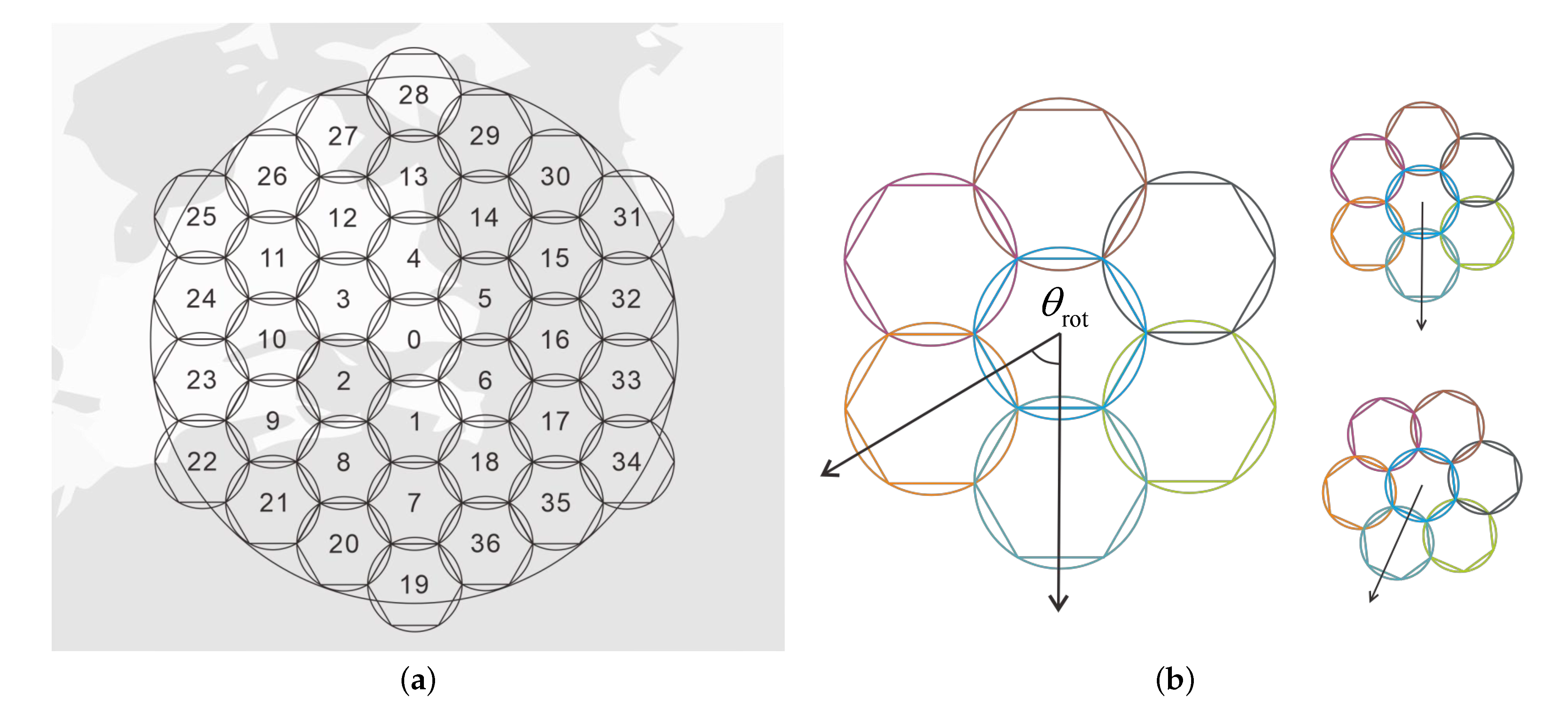
2.4. Channel Allocation Method

During the working life of satellite communication constellations, the spectrum resources used to carry information may unavoidably be idle in time and space. To make full utilization of the spectrum resources, channel allocation among different beams is an effective method. Based on the analysis above, we present a channel allocation method to mitigate the interference caused by NGSO satellites to ground stations in GSO systems. The precondition of proposed channel allocation is that the utilization situation of specific channels should be known to both systems, which means the way of working is cooperative.
Given the initial orbital elements of a targeted satellite in the J2000 Earth centered inertial frame, the position and velocity vectors of the satellite in this frame can be obtained through orbit propagation. For a precise simulation instant, the transformation matrix between different coordinates can be achieved through classical orbital theory [35]. Based on the satellite position vectors, we can calculate the off-axis angles of interfering antenna beam θ 1 and that of the antenna of interfered receiver θ 2 . As defined previously, we have a primary and a secondary systems in a scenario of interference. For the primary system with the GSO communication satellite and ground stations, the channel allocation method stays unaltered all along, while with the continuous motion of the satellite in the secondary system, the channel allocation method should be reconsidered at each time step. An illustration of 37 beams created by NGSO satellites is shown in Figure 8a. For ease of understanding, we mark the beams that work in the same channel by the same color. As shown in Figure 8b, seven beams are marked by seven colors, and they represent seven channels used.
According to the analysis carried out above, we can see that if two beams that work in the same channel are too close to each other, severe interference would take place between the two communication systems. To avoid this situation, before employing channels to certain beams, those beams that are allocated to the same channel and will get too close to their co-channel beams should be excluded. This operation limits the intensity of interference to avoid a remarkable decline of the SINR, while it reduces the number of available channels for each beam and consequently diminishes the computational complexity. However, the minimum beam distance should not be too small, because there may be no available channel allocated to particular beams in that condition.
Denote the channel allocation matrix by A . It identifies which channel is employed by each beam, whose element a i j { 0 , 1 } indicates whether the ith beam is allocated with the jth channel. l a denotes the actual distance between the target beam and the beams that work in the identical channel. Note that, for beams with different tilting angles, perhaps the same distance matches along with different off-axis angles. As we hope to use beam distance to reflect the value of the off-axis angle, in order to treat each distance equally, which means the same distance can stand for the same off-axis angle, the revised distance l r is added to the original data. The revised distance for different beams can be calculated through a similar analysis as shown in Figure 7b. Here, we only consider the revised distance for beams of NGSO satellites based on their tilting angles with respect to the center beam.
The whole configuration of the beams can be optimized. The complete coverage of the HTS is an equilateral hexagon comprised of a certain number of beams. Rotating the configuration will result in significant distance variations between different beams that work in the same channel. Thus, the rotation angle is regarded as an optimization variable. The illustration of rotation angle for seven beams condition is shown in Figure 8b. The equilateral hexagon has the characteristic of central symmetry, so the rotation angle is limited to π / 3 . In order to mitigate the co-channel interference between different communication systems, the maximum total amount of beam distances is regarded as the optimization objective, and the optimization problem can be formulated as
max i = 1 N s l a + l r s . t . i = 1 N s a i j 0 i = 1 N s a i j M p a i j + a k j = 1 l l th 0 θ rot π / 3
where N s stands for the number of interfering satellite beams, and M p is the number of available beam colors of the interfered satellite. The values of i and k should satisfy the condition that two beams represented by integers are adjacent in the topology of the equilateral hexagon of coverage. This optimization problem is typically a mixed integer nonlinear programming problem [36], which could be solved by methods such as enumeration method [37], greedy algorithm [38,39], genetic algorithm [40,41], beam search algorithm [42], and the Monte Carlo method [38,43], among other techniques. And this problem is an NP-hard problem. The enumeration method is preferred when the problem is small-scale. However, when the scale of the problem becomes large enough, the time consumption of the enumeration method is unbearable. Thus, many optimization algorithms are developed to not only achieve optimal solutions, but also greatly reduce the computational time. In this article, a beam search algorithm is mainly selected to solve the presented optimization problem. Beam search is a heuristic algorithm, an adaptation of the branch and bound method [44], and only a certain number of nodes are expanded and evaluated in the search tree. At each level, only the nodes with higher evaluation values are kept for further expansion, and the remaining nodes are pruned off permanently. The beam search-based channel allocation procedure is specified in Algorithm 1.
Algorithm 1: Beam search-based channel allocation method.
Input: Ephemeris of satellites
Output: Allocation matrix A
initialization;
whilenot at end of simulation instantdo
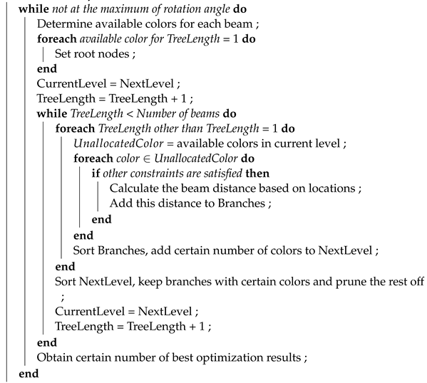
Aerospace 09 00177 i001
end

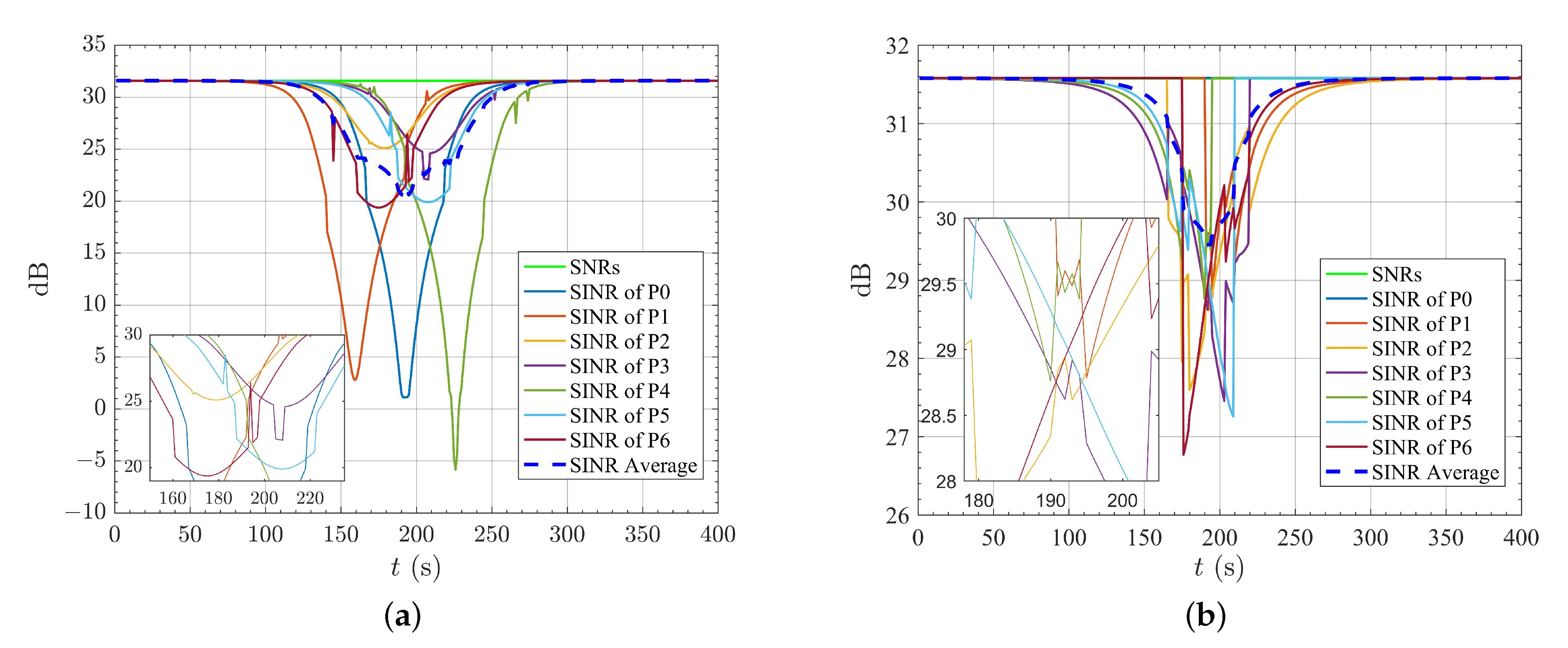
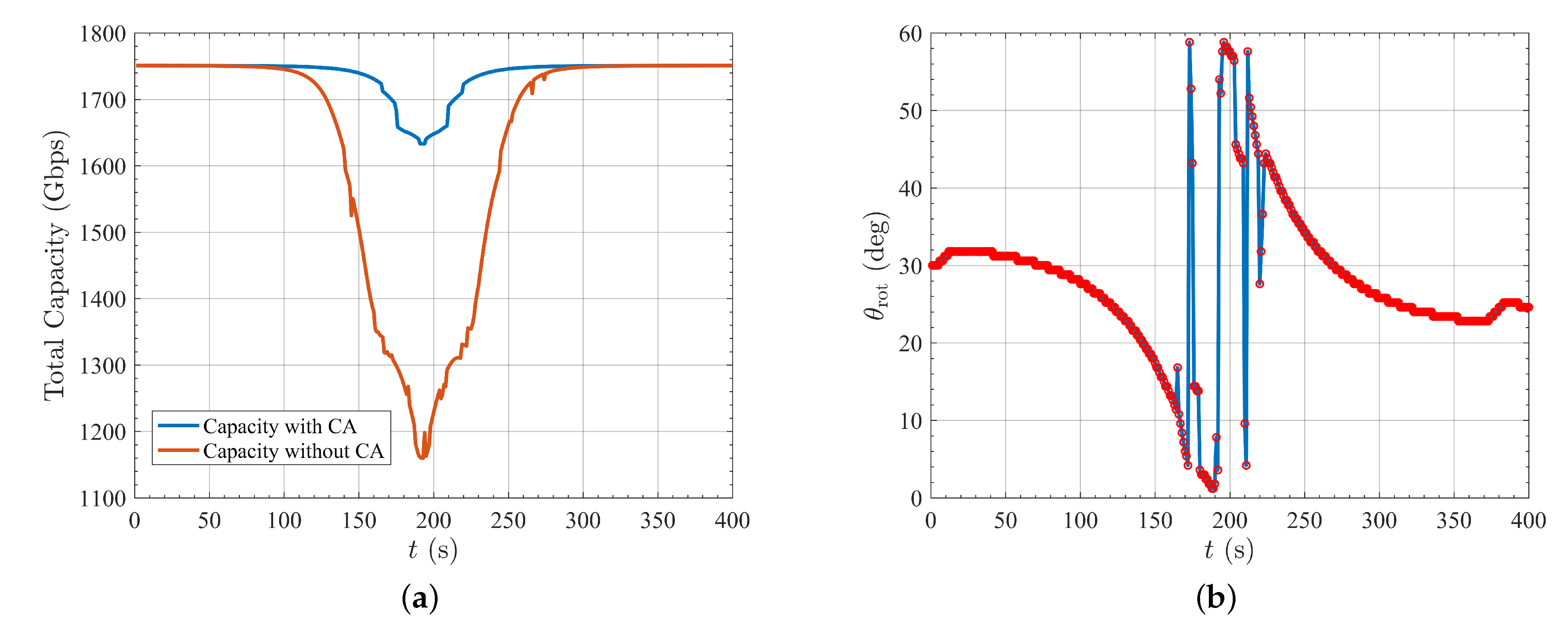
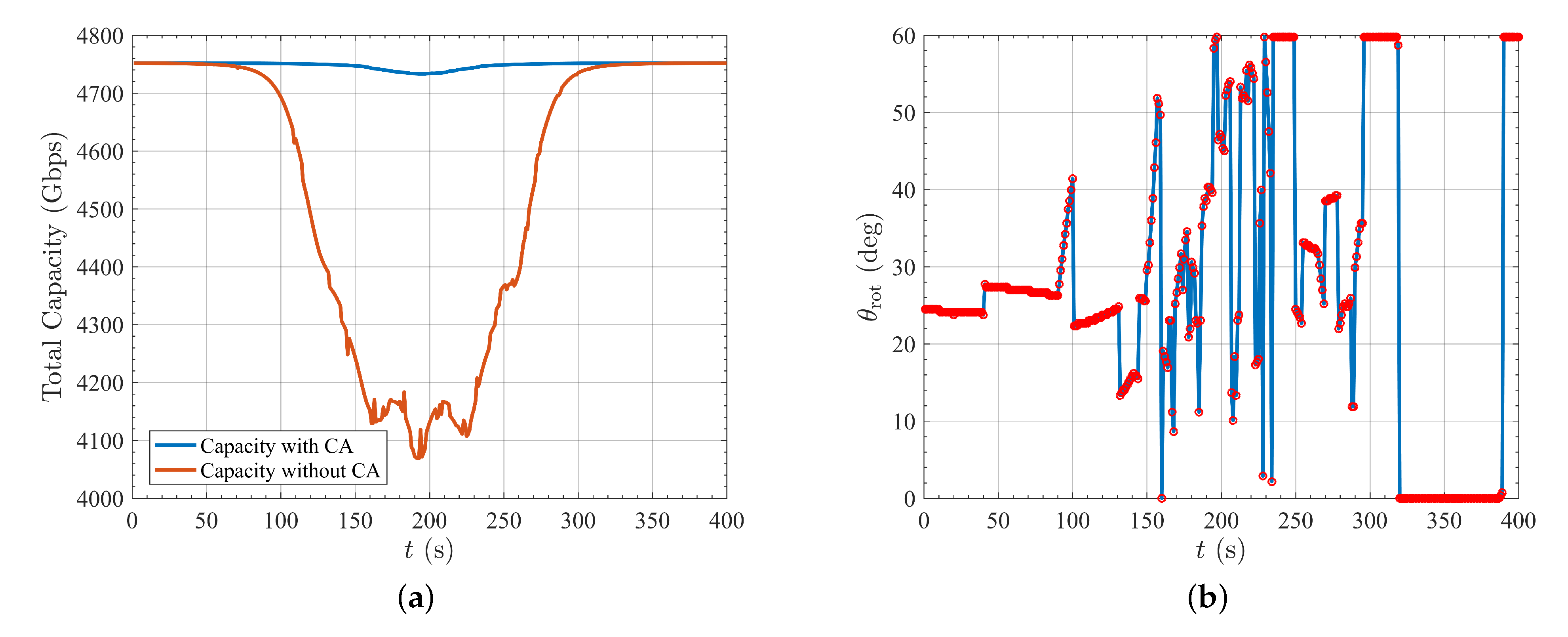
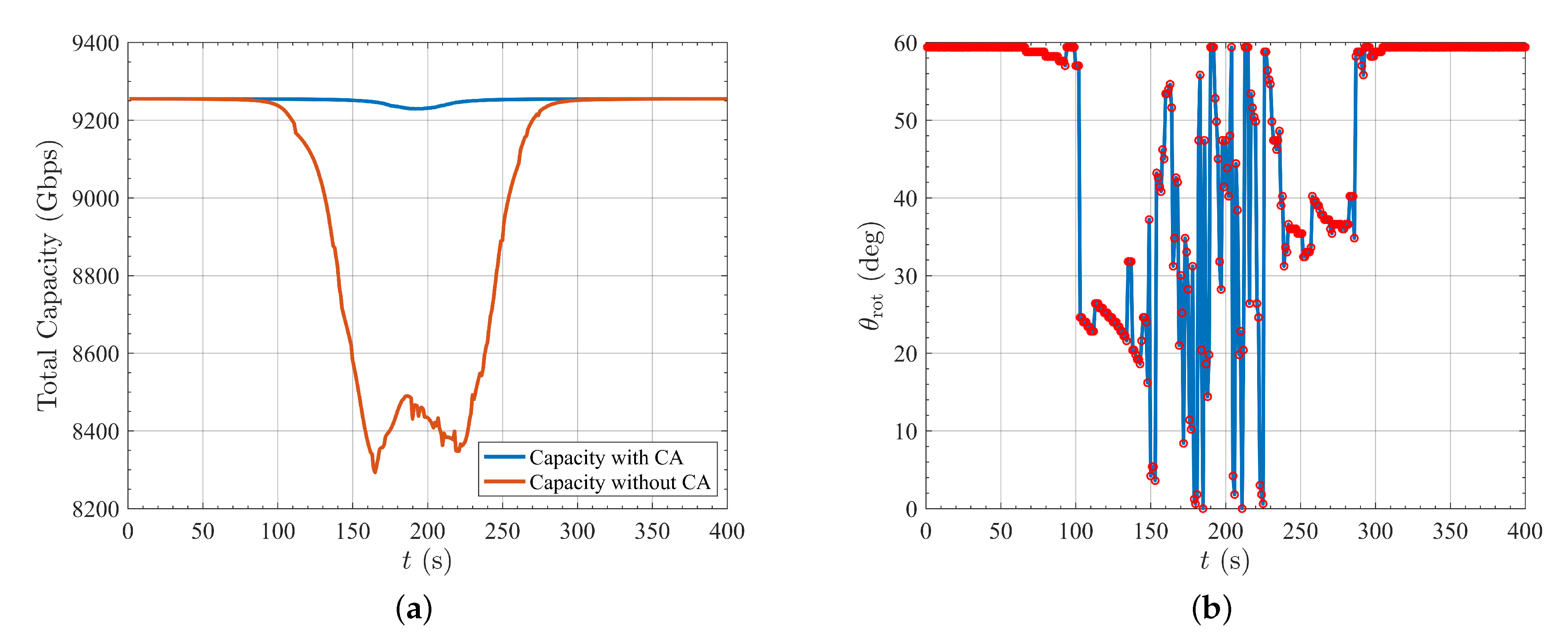
3. Simulation and Results

This section presents the performance of the channel allocation method for the NGSO satellite proposed previously in scenarios of sharing spectrum resources with GSO satellite communication systems. For simplicity, let us assume that the GSO and NGSO satellites are equipped with multi-beam antennas that can produce 7, 19, and 37 beams in the coverage area, which just make up an equilateral hexagon with different levels as illustrated in Figure 8a. The ground stations of the interfered communication system are placed in the centers of these beams, and the antenna beams of the NGSO satellite stay illuminated, which keeps transmitting information constantly. The simulation and orbital parameters are taken as shown in Table 2 and Table 3. The experiments were simulated in the computer with the CPU of i7-10700 2.90 GHz.
The variations of SNR and SINR in different beams with and without channel allocation are described in the following paragraphs. We only zoom in locally on Figure 9 for the 7-beam scenario because there are too many lines for the 19-beam and 37-beam scenarios. The GSO ground stations are in the centers of the beams, so the SNRs are the same for all the ground stations. For convenience, we only use one line to signify the SNRs. In the legend of Figure 9, Pi denotes the GSO ground station located in the beam number i as illustrated in Figure 8a. It is obvious that from the following figures (which regard the evaluation indexes variation of the GSO ground stations in different beams), the value of SNR remains unchanged during the whole simulation period, while the value of SINR is equal to that of SNR during the beginning and end of the simulation period. This is because, at that time, the two satellites are too distant from each other to bring about severe interference. As time goes by, the coverage area of the NGSO satellite starts to overlap with that of the GSO satellite, and the level of interference is augmented. As the NGSO satellite moves in its orbit, it appears above the coverage area of the GSO satellite from south to north. Therefore, we can see that the ground stations whose positions of beam centers are in the middle of the configuration of coverage would bear more severe interference during the simulation period. The SINR of the GSO ground stations after channel allocation increases obviously in its level.
Regarding the scenario with seven beams, the enumeration method and beam search algorithm are both investigated to obtain the solution to channel allocation. The enumeration method takes about half an hour to solve for the solution, while the beam search algorithm takes only about 2 min. From the variation of SINR, we notice that the final results are almost identical, although the computational time is far less for the beam search algorithm. Figure 9a illustrates that the GSO ground stations in the centers of the beams with numbers 1, 0, and 4 suffer more severe interference gradually with the satellites moving from the south to the north. The stations P2 and P6 are placed on the south part of the coverage area so the SINRs decrease earlier compared with P3 and P5. The minimum SINR of each GSO ground station depends on the distance between the station and the interference source. From Figure 9 it is evident that, after channel allocation, the minimum SINR raises from −5 dB to 27 dB, an increment of over 30 dB in SINR is achieved. The average value of SINR also presents an outstanding improvement even in the most severe scenario of interference. As shown in Figure 10, the total capacity of the NGSO satellite, due to its close relationship with the SINR of each link, appears significantly improved as well. Although the rotation angle of the equilateral hexagon configuration of the coverage area brings about a slight improvement in total capacity, it changes a lot during the simulation period. As time passes, the rotation angle progressively drops to 0 from 30 in the beginning. After jumping a few times, the rotation angle gradually decreases from nearly 60° to 30°.
For the scenario where GSO and NGSO satellites are equipped with 19 beams and 37 beams, it is difficult for the enumeration method to solve for the solution, so we only use the beam search algorithm. It takes about ten minutes and half an hour to find the solutions for the 19-beam and 37-beam scenarios, respectively. For the 19-beam scenario, it is clear from Figure 11 that, after channel allocation, the minimum SINR raises from about −10 dB to 31 dB. Moreover, compared with the seven-beam scenario, before channel allocation, five GSO ground stations bear much more severe interference than other stations. It is because when the NGSO satellite moves from south to north, the subsatellite point will directly cross the five GSO beams in the 19-beam scenario. As shown in Figure 12, due to the tremendous increment in SINR after channel allocation, total capacity presents less sharp variation compared with the seven-beam scenario. As for the change of rotation angle, it has much jumping in its value during the simulation period, and it is hard to find the rule of change behind it. The variation of SNR and SINR are presented in Figure 13 and the change of total capacity and rotation angle are presented in Figure 14 for the 37-beam scenario. It is evident that, after channel allocation, the SINR has an apparent elevation, and the total capacity rises to a level where the interference is negligible, demonstrating the effectiveness of the presented channel allocation method. The rotation angle stays close to 60° at the beginning and the end of the simulation, but its value is widely distributed within a reasonable range.

4. Conclusions

This paper focuses on interference avoidance with the existence of NGSO communication satellites equipped with multi-beam antennas. Channel allocation is chosen as our penetration point to reduce the interference of NGSO satellites system to other communication systems. A new channel allocation method to mitigate the interference based on the beam search algorithm has been developed. In our analysis, we take the scenario of sharing spectrum resources with a GSO satellite as an example. The relationship between the level of interference and the distance of beam centers has been explored. It is worth noticing that, for beams with a tilting angle, which is a common feature for satellites with multi-beam antennas, the tilting angle could bring about a significant change for the relationship between the distance of beam centers and off-axis angles. Therefore, a revised distance is introduced in order to reflect the interference more accurately using beam distance. We constrain that the distance between different co-channel beams with the condition that they should not be too close to each other to avoid severe interference. Furthermore, the rotation of the complete coverage area is taken into consideration as well to testify its effectiveness on mitigation of interference. The enumeration method is used to obtain the solution to the proposed optimization problem when the number of beams is small, and the beam search algorithm is selected when the scale of the problem is large so it would result in a shorter computational time.
Several numerical simulations have demonstrated that the proposed channel allocation method could very effectively augment the SINR and total capacity of the interfered satellite system. The potential interference can be significantly mitigated. The simulation tells that the rotation of configuration of coverage areas has a slight impact on the increment of the total capacity of the communication system. It should be noted that, although in this article we select a GSO system to be the interfered system, the proposed channel allocation method is well suited for the scenario of an NGSO system suffering interference from other systems.

Author Contributions

H.Z. completed preliminary research and provided the numerical part; H.Z. and F.J. conceived and wrote the paper; and F.J. and D.R. supervised the overall work and reviewed the paper. All authors have read and agreed to the published version of the manuscript.

Funding

This work was supported by the National Natural Science Foundation of China (No. 12022214).

Institutional Review Board Statement

Not applicable.

Informed Consent Statement

Not applicable.

Data Availability Statement

The data presented in this study are available on request from the corresponding author.

Conflicts of Interest

The authors declare no conflict of interest.

Abbreviations

NGSONon-geostationary orbit
GSOGeostationary orbit
LEOLow Earth orbit
HTSHigh throughput satellite
CAChannel allocation
ITUInternational Telecommunication Union
SNRSignal to noise ratio
SINRSignal to interference plus noise ratio
NPNon-deterministic polynomial
RAANRight ascension of the ascending node

References

  1. Wu, W.W.; Miller, E.F.; Pritchard, W.L.; Pickholtz, R.L. Mobile satellite communications. Proc. IEEE 1994, 82, 1431–1448. [Google Scholar] [CrossRef]
  2. Evans, J.V. Satellite systems for personal communications. Proc. IEEE 1998, 86, 1325–1341. [Google Scholar] [CrossRef]
  3. Hanson, W. A global Internet: The next four billion users. New Space 2015, 3, 204–207. [Google Scholar] [CrossRef]
  4. Curran, J.; Fenton, N.; Freedman, D. Misunderstanding the Internet; Routledge: London, UK, 2016. [Google Scholar]
  5. Internet World Stats. World Internet Usage and Population Statistics 2020. Internet World Stats: 2020. Available online: https://www.internetworldstats.com/stats.htm (accessed on 1 February 2022).
  6. Lu, Y.; Zheng, X. 6G: A survey on technologies, scenarios, challenges, and the related issues. J. Ind. Inf. Integr. 2020, 19, 100158. [Google Scholar] [CrossRef]
  7. Nguyen, D.C.; Ding, M.; Pathirana, P.N.; Seneviratne, A.; Li, J.; Niyato, D.; Dobre, O.; Poor, H.V. 6G Internet of Things: A Comprehensive Survey. IEEE Internet Things J. 2021, 9, 359–383. [Google Scholar] [CrossRef]
  8. Zhen, L.; Bashir, A.K.; Yu, K.; Al-Otaibi, Y.D.; Foh, C.H.; Xiao, P. Energy-efficient random access for LEO satellite-assisted 6G internet of remote things. IEEE Internet Things J. 2020, 8, 5114–5128. [Google Scholar] [CrossRef]
  9. Jones, H. Much Lower Launch Costs Make Resupply Cheaper Than Recycling for Space Life Support. In Proceedings of the 47th International Conference on Environmental Systems, Charleston, SC, USA, 16–20 July 2017. [Google Scholar]
  10. Federal Communications Commission. Application For Approval for Orbital Deployment and Operating Authority for the SpaceX NGSO Satellite System; Federal Communications Commission: Washington, DC, USA, 2016.
  11. Federal Communications Commission. Application for Modification of Authorization for the SpaceX NGSO Satellite System; Federal Communications Commission: Washington, DC, USA, 2018.
  12. Barnett, R. Oneweb Non-Geostationary Satellite System: Technical Information to Supplement Schedules—Attachment to Fcc Application Sat-loi-20160428-00041; Tech. Rep. SAT-LOI-20160428-00041; Federal Communications Commission: Washington, DC, USA, 2016. [Google Scholar]
  13. Barnett, R. Oneweb Non-Geostationary Satellite System: Attachment a—Technical Information to Supplement Schedule S; Tech. Rep. SAT-MOD-20180319-00022; Federal Communications Commission: Washington, DC, USA, 2018. [Google Scholar]
  14. Ashford, E.W. Non-Geo systems—Where have all the satellites gone? Acta Astronaut. 2004, 55, 649–657. [Google Scholar] [CrossRef]
  15. Su, Y.; Liu, Y.; Zhou, Y.; Yuan, J.; Cao, H.; Shi, J. Broadband LEO satellite communications: Architectures and key technologies. IEEE Wirel. Commun. 2019, 26, 55–61. [Google Scholar] [CrossRef]
  16. Bhattacherjee, D.; Aqeel, W.; Bozkurt, I.N.; Aguirre, A.; Chandrasekaran, B.; Godfrey, P.B.; Laughlin, G.; Maggs, B.; Singla, A. Gearing up for the 21st century space race. In Proceedings of the 17th ACM Workshop on Hot Topics in Networks, Redmond, WA, USA, 15–16 November 2018; pp. 113–119. [Google Scholar]
  17. Butash, T.; Garland, P.; Evans, B. Non-geostationary satellite orbit communications satellite constellations history. Int. J. Satell. Commun. Netw. 2021, 39, 1–5. [Google Scholar] [CrossRef]
  18. Tang, J.; Bian, D.; Li, G.; Hu, J.; Cheng, J. Resource Allocation for LEO Beam-Hopping Satellites in a Spectrum Sharing Scenario. IEEE Access 2021, 9, 56468–56478. [Google Scholar] [CrossRef]
  19. Zhang, C.; Jin, J.; Zhang, H.; Li, T. Spectral coexistence between LEO and GEO satellites by optimizing direction normal of phased array antennas. China Commun. 2018, 15, 18–27. [Google Scholar] [CrossRef]
  20. Nelson, R.A.; Pritchard, W. Interference between satellite systems in non-geostationary orbits. Int. J. Satell. Commun. 1994, 12, 95–105. [Google Scholar] [CrossRef]
  21. Wang, A. Optimization on constellation design for spectrum sharing among satellite networks. In Proceedings of the 17th AIAA International Communications Satellite Systems Conference and Exhibit, Yokohama, Japan, 23–27 February 1998; p. 1202. [Google Scholar]
  22. Lin, Z.; Jin, J.; Yan, J.; Kuang, L. Fast Calculation of the Probability Distribution of Interference Involving Multiple Mega-Constellations. In Proceedings of the International Conference on Space Information Network; Springer: Singapore, 2020; pp. 18–34. [Google Scholar]
  23. Del Portillo, I.; Cameron, B.G.; Crawley, E.F. A technical comparison of three low earth orbit satellite constellation systems to provide global broadband. Acta Astronaut. 2019, 159, 123–135. [Google Scholar] [CrossRef]
  24. Xia, S.; Jiang, Q.; Zou, C.; Li, G. Beam coverage comparison of LEO satellite systems based on user diversification. IEEE Access 2019, 7, 181656–181667. [Google Scholar] [CrossRef]
  25. Li, R.; Gu, P.; Hua, C. Optimal beam power control for co-existing multibeam GEO and LEO satellite system. In Proceedings of the 2019 11th International Conference on Wireless Communications and Signal Processing (WCSP), Xi’an, China, 23–25 October 2019; pp. 1–6. [Google Scholar]
  26. Shen, K.; Yu, W. Fractional programming for communication systems—Part I: Power control and beamforming. IEEE Trans. Signal Process. 2018, 66, 2616–2630. [Google Scholar] [CrossRef] [Green Version]
  27. Liu, S.; Hu, X.; Wang, W. Deep reinforcement learning based dynamic channel allocation algorithm in multibeam satellite systems. IEEE Access 2018, 6, 15733–15742. [Google Scholar] [CrossRef]
  28. Sharma, S.K.; Chatzinotas, S.; Ottersten, B. Cognitive beamhopping for spectral coexistence of multibeam satellites. Int. J. Satell. Commun. Netw. 2015, 33, 69–91. [Google Scholar] [CrossRef] [Green Version]
  29. Ren, Z.; Jin, J.; Li, W.; Zhan, Y. Intelligent Action Selection for NGSO Networks with Interference Constraints: A Modified Q-Learning Approach. IEEE Trans. Aerosp. Electron. Syst. 2021. [Google Scholar] [CrossRef]
  30. Wang, C.; Bian, D.; Zhang, G.; Cheng, J.; Li, Y. A novel dynamic spectrum-sharing method for integrated wireless multimedia sensors and cognitive satellite networks. Sensors 2018, 18, 3904. [Google Scholar] [CrossRef] [Green Version]
  31. Wang, C.; Bian, D.; Shi, S.; Xu, J.; Zhang, G. A novel cognitive satellite network with GEO and LEO broadband systems in the downlink case. IEEE Access 2018, 6, 25987–26000. [Google Scholar] [CrossRef]
  32. ITU-R. Satellite aNtenna Radiation Patterns for Non-Geostationary Orbit Satellite Antennas Operating in the Fixed-Satellite Service below 30 GHz: ITU-R S. 1528, 2001. Available online: https://www.itu.int/dms_pubrec/itu-r/rec/s/R-REC-S.1528-0-200106-I!!PDF-E.pdf (accessed on 1 February 2022).
  33. ITU-R. Satellite Antenna Radiation Pattern for Use as a Design Objective in the Fixed-Satellite Service Employing Geostationary Satellites: ITU-R S. 672 4. [Sl: Sn] 1997. Available online: https://www.itu.int/dms_pubrec/itu-r/rec/s/R-REC-S.672-4-199709-I!!PDF-E.pdf (accessed on 1 February 2022).
  34. ITU-R. ITU Radio Regulations; ITU-R: Geneva, Switzerland, 2016. [Google Scholar]
  35. Curtis, H. Orbital Mechanics for Engineering Students: Revised Reprint; Butterworth-Heinemann: Oxford, UK, 2020. [Google Scholar]
  36. Lee, J.; Leyffer, S. Mixed Integer Nonlinear Programming; Springer Science & Business Media: Berlin/Heidelberg, Germany, 2011; Volume 154. [Google Scholar]
  37. Lageweg, B.; Lenstra, J.; Rinnooy Kan, A. Job-shop scheduling by implicit enumeration. Manag. Sci. 1977, 24, 441–450. [Google Scholar] [CrossRef]
  38. Zhang, T.J.; Wolz, D.; Shen, H.X.; Luo, Y.Z. Spanning tree trajectory optimization in the galaxy space. Astrodynamics 2021, 5, 27–37. [Google Scholar] [CrossRef]
  39. Vince, A. A framework for the greedy algorithm. Discret. Appl. Math. 2002, 121, 247–260. [Google Scholar] [CrossRef] [Green Version]
  40. Whitley, D. A genetic algorithm tutorial. Stat. Comput. 1994, 4, 65–85. [Google Scholar] [CrossRef]
  41. Huang, A.Y.; Yan, B.; Li, Z.Y.; Shu, P.; Luo, Y.Z.; Yang, Z. Orbit design and mission planning for global observation of Jupiter. Astrodynamics 2021, 5, 39–48. [Google Scholar] [CrossRef]
  42. Sabuncuoglu, I.; Bayiz, M. Job shop scheduling with beam search. Eur. J. Oper. Res. 1999, 118, 390–412. [Google Scholar] [CrossRef]
  43. Zhang, C.; Jin, J.; Kuang, L.; Yan, J. LEO constellation design methodology for observing multi-targets. Astrodynamics 2018, 2, 121–131. [Google Scholar] [CrossRef]
  44. Yang, H.; Tang, G.; Jiang, F. Optimization of observing sequence based on nominal trajectories of symmetric observing configuration. Astrodynamics 2018, 2, 25–37. [Google Scholar] [CrossRef]
Figure 1. An illustration of the downlink interference scenario.
Aerospace 09 00177 g001
Figure 2. Utilization of overlaped frequency bands.
Aerospace 09 00177 g002
Figure 3. Variation of gain of antennas with off-axis angle for different antenna radiation patterns.
Aerospace 09 00177 g003
Figure 4. The downlink scenarios where beams have no tilting angle and only NGSO satellite beam have a tilting angle. (a) Pointing of NGSO and GSO satellites beams without tilting angle; (b) Pointing of NGSO satellite beams with tilting angle β 1 .
Aerospace 09 00177 g004
Figure 5. The downlink scenarios where GSO satellite beams have tilting angle rendering the beam center farther away or closer to the other center. (a) Pointing of GSO satellite beams with tilting angle β 2 making it farther away from the beam center of NGSO satellite; (b) Pointing of GSO satellite beams with tilting angle β 2 making it closer to the beam center of NGSO satellite.
Aerospace 09 00177 g005
Figure 6. Relationship between off-axis angles θ 1 , θ 2 , and F u and beam distance l, with different tilting angles β 1 and β 2 . (a) Relationship between variations of θ 1 , θ 2 , and beam distance l with different value of tilting angle β 1 and β 2 ; (b) Relationship between F u in dB, F u in number, and beam distance l with different value of tilting angle β 1 and β 2 .
Aerospace 09 00177 g006
Figure 7. Downlink scenario where pointing of NGSO satellite beams have different tilting angles and relationship between off-axis angle and beam distance l with different tilting angles. (a) Pointing of NGSO satellite beams with different tilting angles; (b) Relationship between variation of off-axis angle and beam distance l when beams have different tilting angles.
Aerospace 09 00177 g007
Figure 8. Layout of NGSO satellite beams and illustration of rotation angle. (a) Layout of NGSO satellite beams with 37 beams; (b) Illustration of rotation angle for seven-beam scenario.
Aerospace 09 00177 g008
Figure 9. SNR and SINR of different GSO ground stations in different beams for the seven-beam scenario without and with channel allocation. (a) SNR and SINR of different GSO ground stations in different beams for the seven-beam scenario without channel allocation; (b) SNR and SINR of different GSO ground stations in different beams for the seven-beam scenario with channel allocation.
Aerospace 09 00177 g009
Figure 10. Change of total capacity with and without channel allocation and variation of rotation angle for the seven-beam scenario. (a) Change of total capacity with and without channel allocation for the seven-beam scenario; (b) Variation of rotation angle for the seven-beam scenario.
Aerospace 09 00177 g010
Figure 11. SNR and SINR of different GSO ground stations in different beams for the 19-beam scenario without and with channel allocation. (a) SNR and SINR of different GSO ground stations in different beams for the 19-beam scenario without channel allocation; (b) SNR and SINR of different GSO ground stations in different beams for the 19-beam scenario with channel allocation.
Aerospace 09 00177 g011
Figure 12. Change of total capacity with and without channel allocation and variation of rotation angle for the 19-beam scenario. (a) Change of total capacity with and without channel allocation for the 19-beam scenario; (b) Variation of rotation angle for the 19-beam scenario.
Aerospace 09 00177 g012
Figure 13. SNR and SINR of different GSO ground stations in different beams for the 37-beam scenario without and with channel allocation. (a) SNR and SINR of different GSO ground stations in different beams for the 37-beam scenario without channel allocation; (b) SNR and SINR of different GSO ground stations in different beams for the 37-beam scenario with channel allocation.
Aerospace 09 00177 g013
Figure 14. Change of total capacity with and without channel allocation and variation of rotation angle for the 37-beam scenario. (a) Change of total capacity with and without channel allocation for the 37-beam scenario; (b) Variation of rotation angle for the 37-beam scenario.
Aerospace 09 00177 g014
Table 1. Simulation parameters of antenna gains.
ParametersValue
Downlink carrier frequency, f20 GHz
GSO satellite
GSO maximum transmit gain, G mG 45.39 dBi
GSO 3 dB beamwidth1.259
Radio of major axis to minor axis, z1.5
near-in-side-lobe level, L N 20 dB
NGSO satellite
NGSO maximum transmit gain, G mL 37.65 dBi
NGSO 3 dB beamwidth11.58
GSO ground station
Antenna diameter, D1.2 m
Maximum receive gain, G mr 45.76 dBi
Table 2. Simulation parameters.
Simulation ParametersValue
Simulation UTC begin time, t b 1 May 2030 04:00:00
Simulation UTC end time, t e 1 May 2030 04:06:40
Time step, Δ t 1 s
Earth equatorial radius, R e 6378 km
Boltzmann constant, κ 1.38 × 10 23 W/(Hz · K)
Downlink carrier frequency, f20 GHz
Bandwidth of each beam, B W 25 MHz
GSO satellite
Latitude of GSO center beam, φ 0
Longitude of GSO center beam, Λ 21.26
Transmit power of GSO satellite, P tG 18.57 dBW
GSO maximum transmit gain, G mG 45.39 dBi
GSO 3 dB beamwidth for 7 and 19 beams1.259
GSO 3 dB beamwidth for 37 beams0.6295
Radio of major axis to minor axis, z1.5
near-in-side-lobe level, L N 20 dB
Number of GSO beams7, 19, 37
NGSO satellite
Transmit power of NGSO satellite, P tL 12.55 dBW
NGSO maximum transmit gain, G mL 37.65 dBi
NGSO 3 dB beamwidth for 7 and 19 beams11.58
NGSO 3 dB beamwidth for 37 beams5.79
Number of NGSO beams7, 19, 37
GSO ground station
Noise temperature of receive antenna, T r 210 K
Antenna diameter, D1.2 m
Maximum receive gain, G mr 45.76 dBi
Table 3. Orbital parameters of GSO and NGSO satellites.
Orbital ParametersGSONGSO
Orbital altitude, h35,786.14 km1450 km
Eccentricity, e00
RAAN, Ω 0301
Orbital inclination, i087.5
Argument of perigee, ω 00
True anomaly, θ 300 350
Publisher’s Note: MDPI stays neutral with regard to jurisdictional claims in published maps and institutional affiliations.

