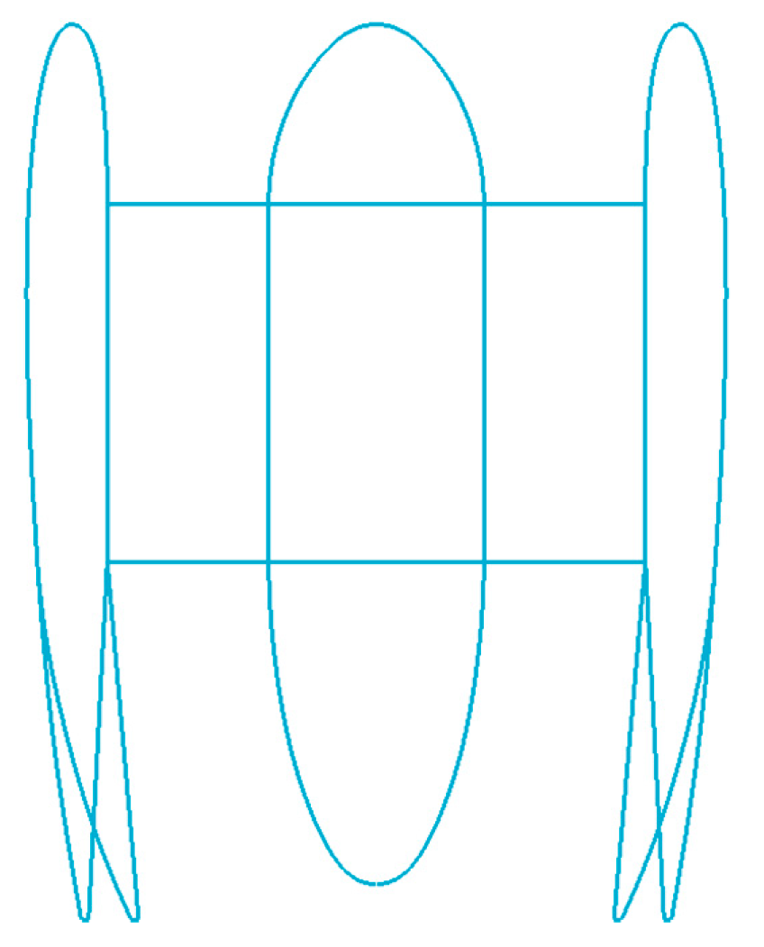
Figure 1.
Duct profile of the 150 ducted fan.
Figure 1.
Duct profile of the 150 ducted fan.
Figure 2.
Geometry of the 150 ducted fan.
Figure 2.
Geometry of the 150 ducted fan.
Figure 3.
Picture of the 150 ducted fan during the test.
Figure 3.
Picture of the 150 ducted fan during the test.
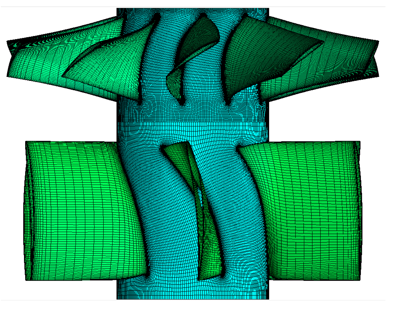
Figure 4.
Schematic of the blade grid in the MRF method.
Figure 4.
Schematic of the blade grid in the MRF method.
Figure 5.
Schematic of the gird in the MSM.
Figure 5.
Schematic of the gird in the MSM.
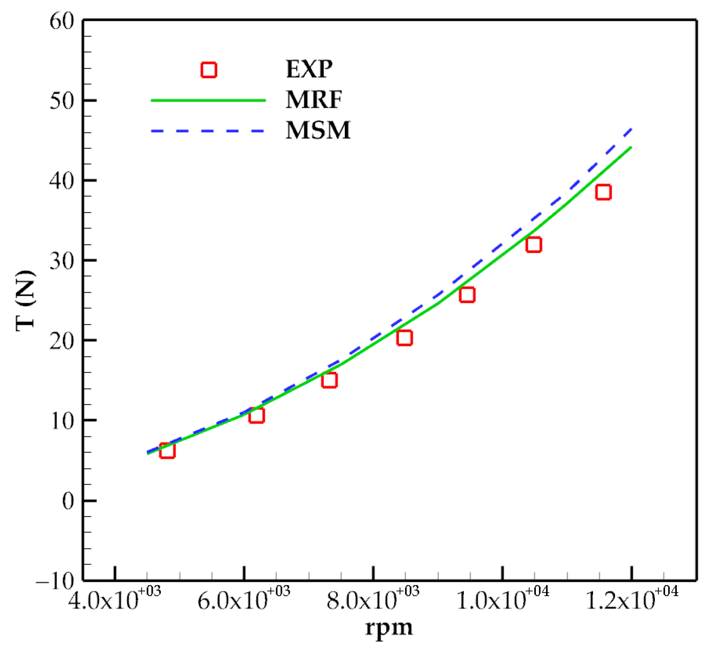
Figure 6.
Comparison of the thrust of the ducted fan obtained by different methods.
Figure 6.
Comparison of the thrust of the ducted fan obtained by different methods.
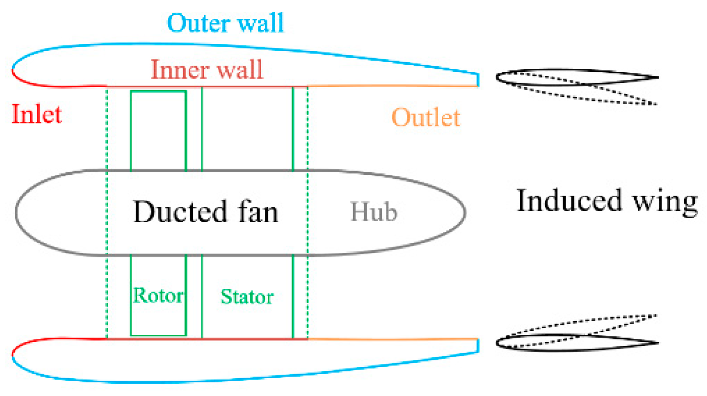
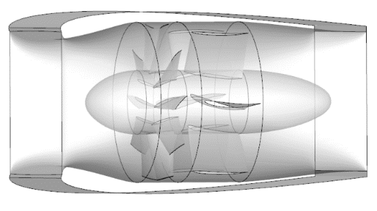
Figure 7.
Schematic diagram of the distributed ducted fan system.
Figure 7.
Schematic diagram of the distributed ducted fan system.
Figure 8.
Schematic of the variable area nozzle.
Figure 8.
Schematic of the variable area nozzle.
Figure 9.
Airfoils of the blade of the ducted fan.
Figure 9.
Airfoils of the blade of the ducted fan.
Figure 10.
Distribution of the chord length and torsional angle of the rotor and stator: (a) Rotor; (b) Stator.
Figure 10.
Distribution of the chord length and torsional angle of the rotor and stator: (a) Rotor; (b) Stator.
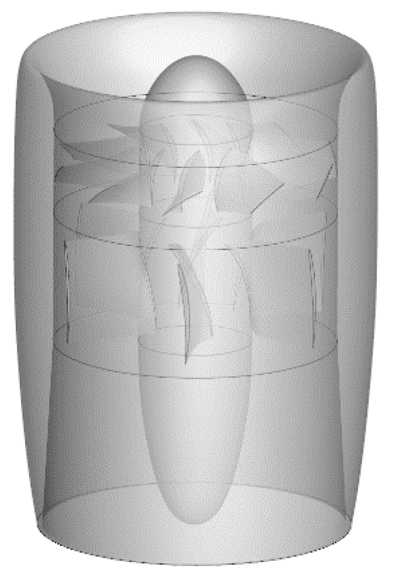
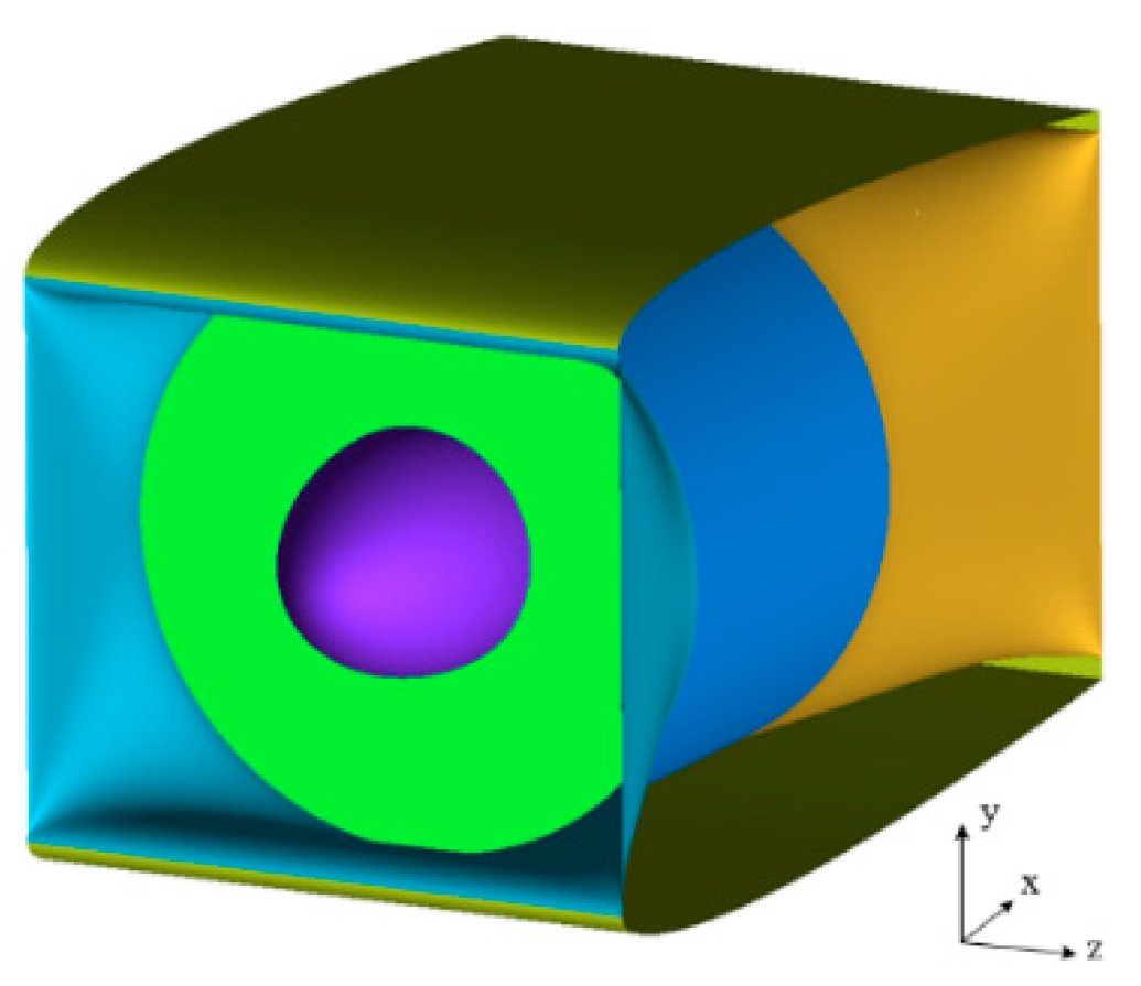
Figure 11.
Schematic diagram of the calculation unit of the distributed ducted fan system.
Figure 11.
Schematic diagram of the calculation unit of the distributed ducted fan system.
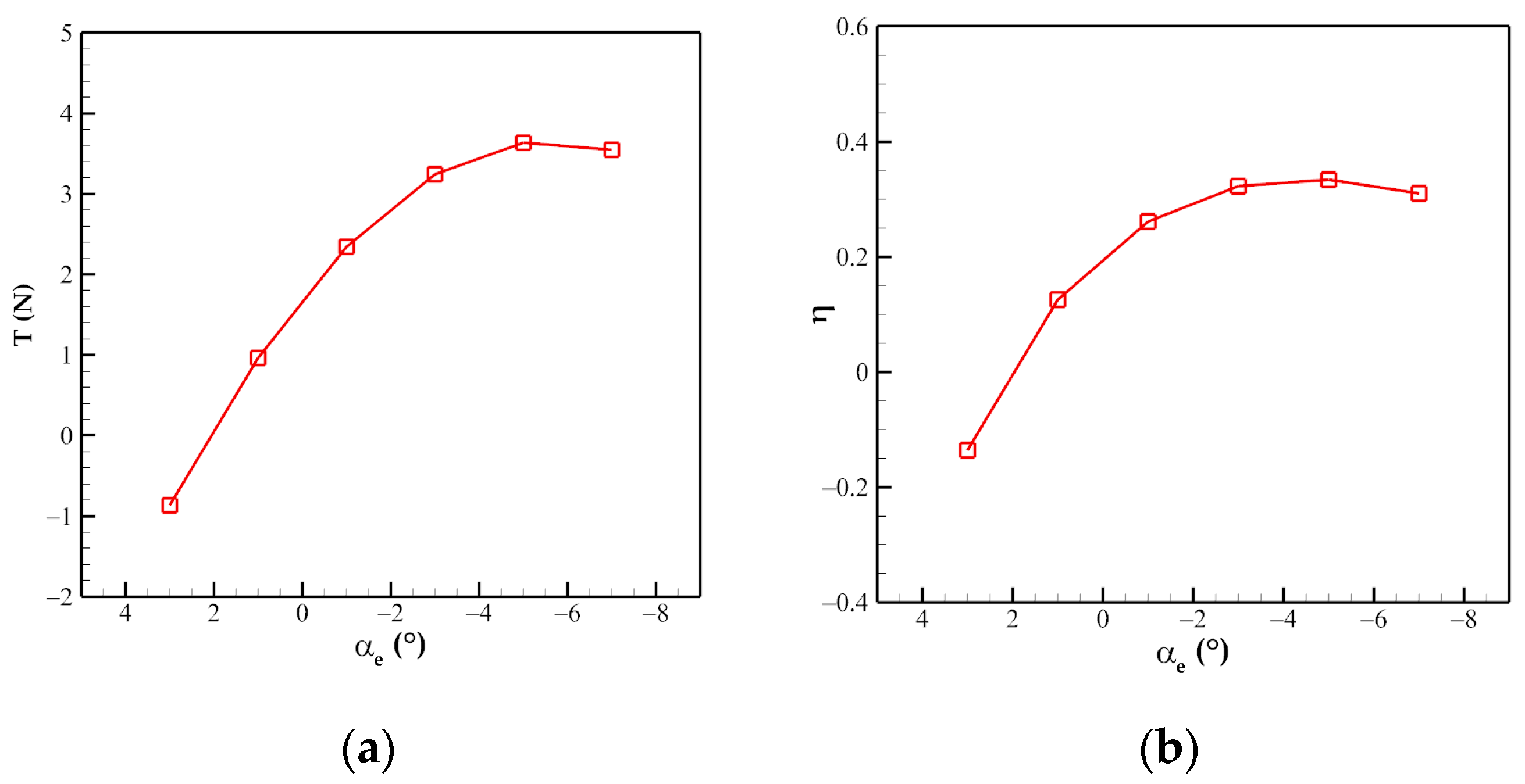
Figure 12.
Variation of cruise performance of the distributed ducted fan unit with different outlet expansion angles: (a) Thrust; (b) Efficiency.
Figure 12.
Variation of cruise performance of the distributed ducted fan unit with different outlet expansion angles: (a) Thrust; (b) Efficiency.
Figure 13.
Comparison of surface pressure of the distributed ducted fan unit in different flight phases: (a) Hover; (b) Cruise.
Figure 13.
Comparison of surface pressure of the distributed ducted fan unit in different flight phases: (a) Hover; (b) Cruise.
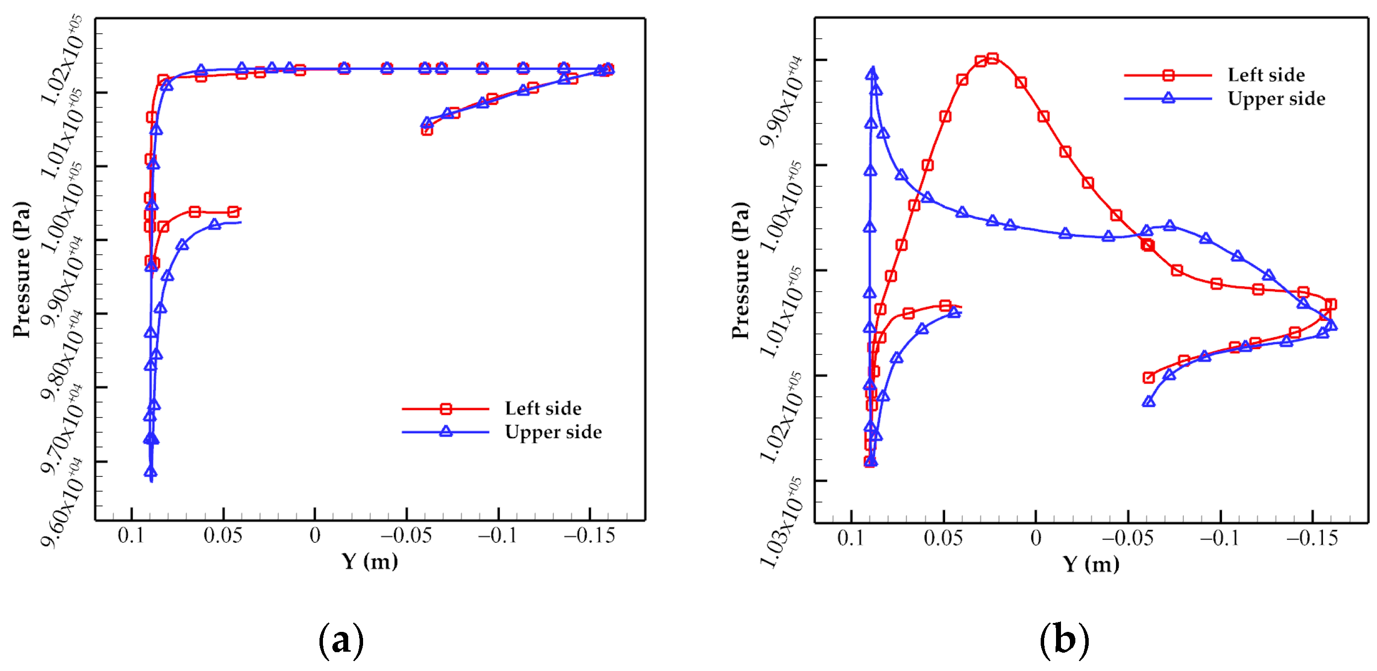
Figure 14.
Comparison of the pressure distribution of the duct in different flight phases: (a) Hover; (b) Cruise.
Figure 14.
Comparison of the pressure distribution of the duct in different flight phases: (a) Hover; (b) Cruise.
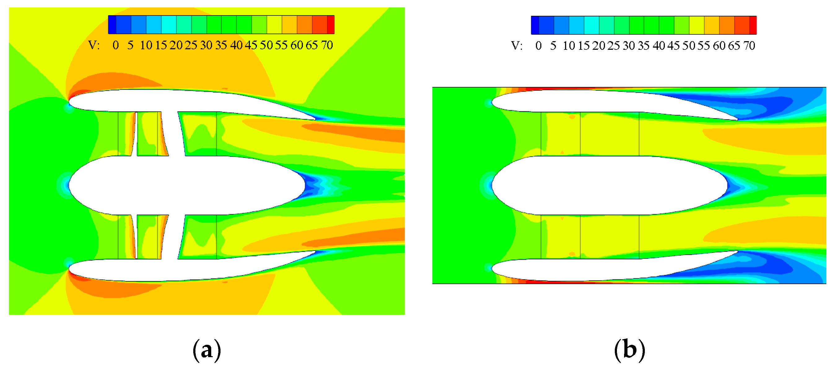
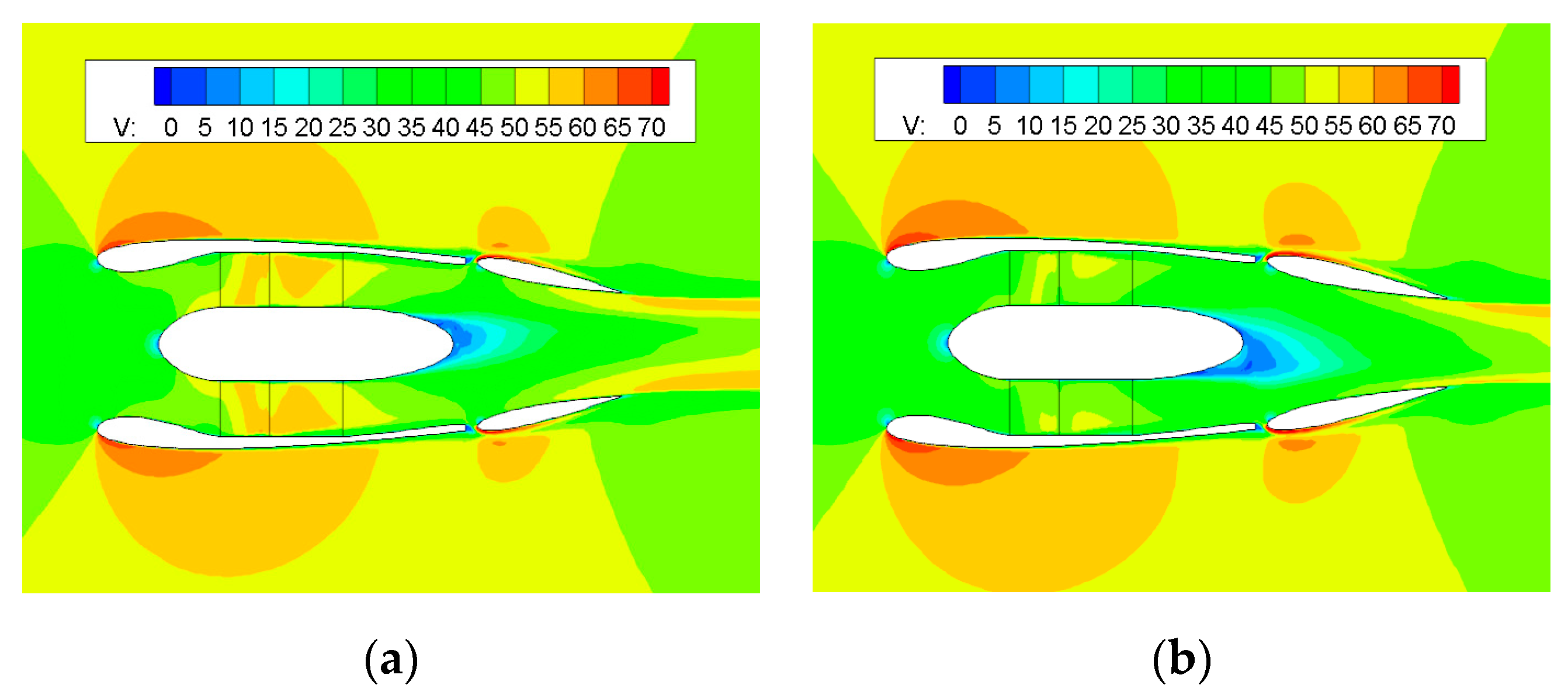
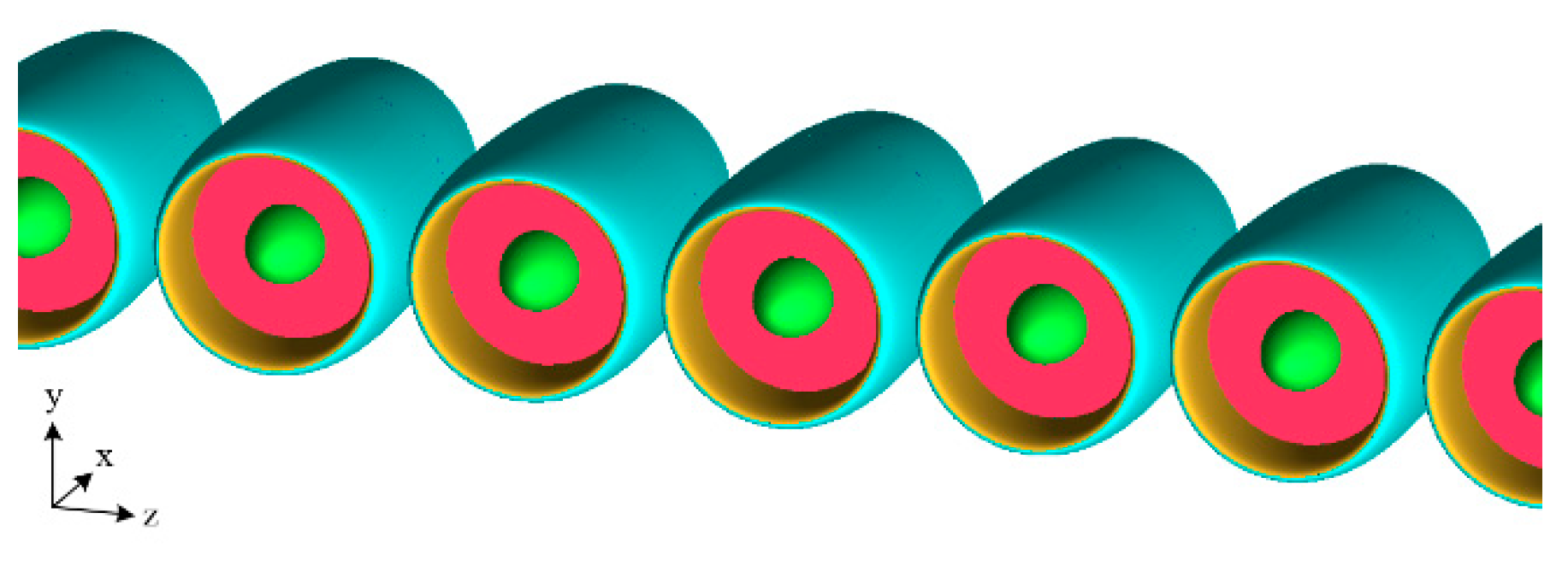
Figure 15.
Comparison of the velocity image of the distributed ducted fan unit in cruise flight: (a) z = 0 m; (b) y = 0 m.
Figure 15.
Comparison of the velocity image of the distributed ducted fan unit in cruise flight: (a) z = 0 m; (b) y = 0 m.
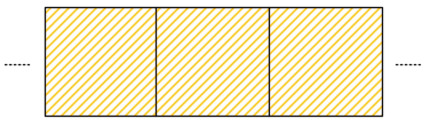
Figure 16.
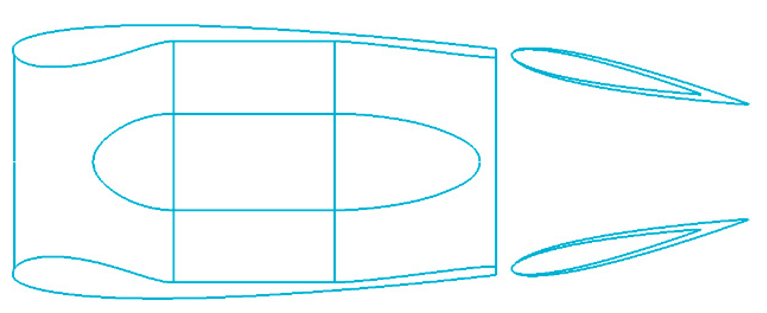
Distributed ducted fan system with the rectangular duct.
Figure 16.
Distributed ducted fan system with the rectangular duct.
Figure 17.
Configuration of the new distributed ducted fan system.
Figure 17.
Configuration of the new distributed ducted fan system.
Figure 18.
Inlet and outlet of the distributed ducted fan unit: (a) “Rectangle to circle” inlet; (b) “Circle to rectangle” outlet.
Figure 18.
Inlet and outlet of the distributed ducted fan unit: (a) “Rectangle to circle” inlet; (b) “Circle to rectangle” outlet.
Figure 19.
Schematic diagram of the distributed ducted fan unit.
Figure 19.
Schematic diagram of the distributed ducted fan unit.
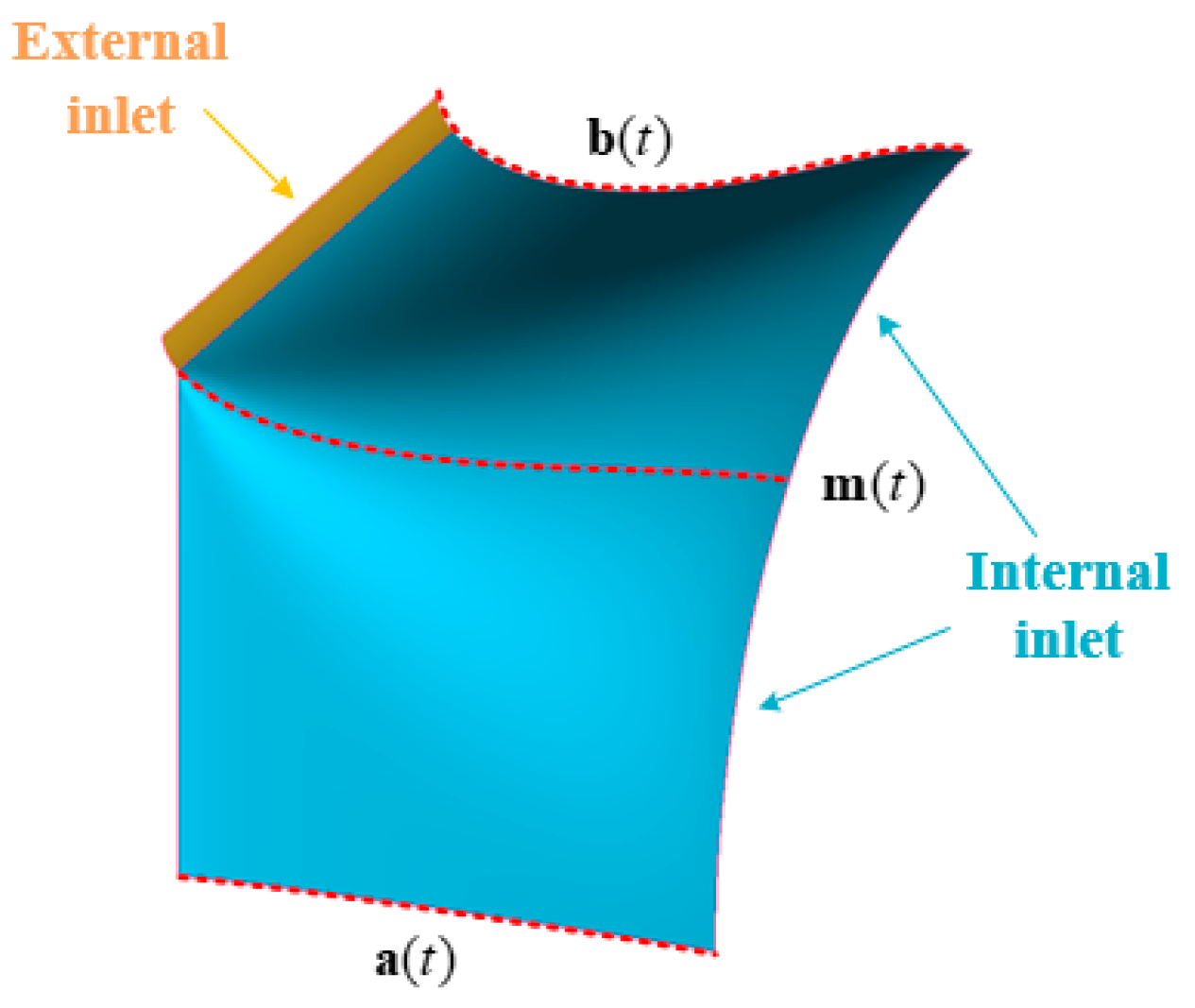
Figure 20.
Schematic diagram of the inlet parameterization.
Figure 20.
Schematic diagram of the inlet parameterization.
Figure 21.
Multi-objective design process of the distributed ducted fan system.
Figure 21.
Multi-objective design process of the distributed ducted fan system.
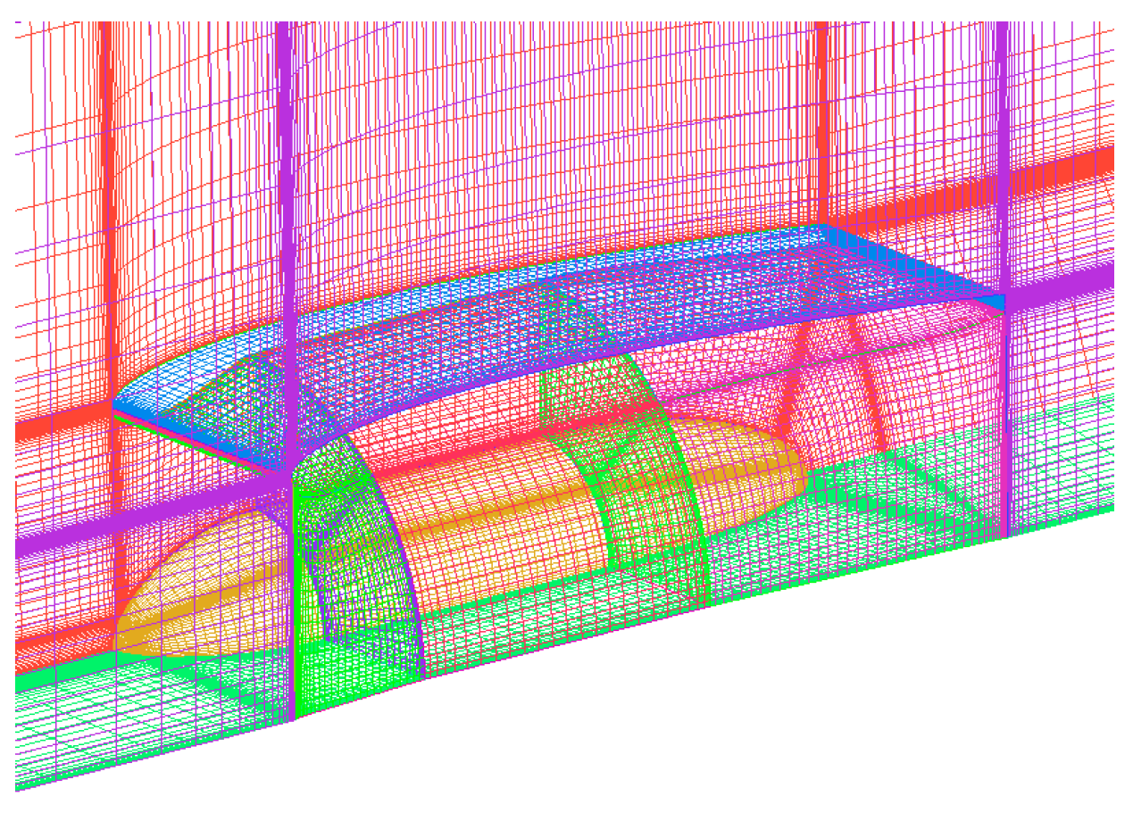
Figure 22.
Schematic of the 1/4 calculation model of the multi-objective optimization.
Figure 22.
Schematic of the 1/4 calculation model of the multi-objective optimization.
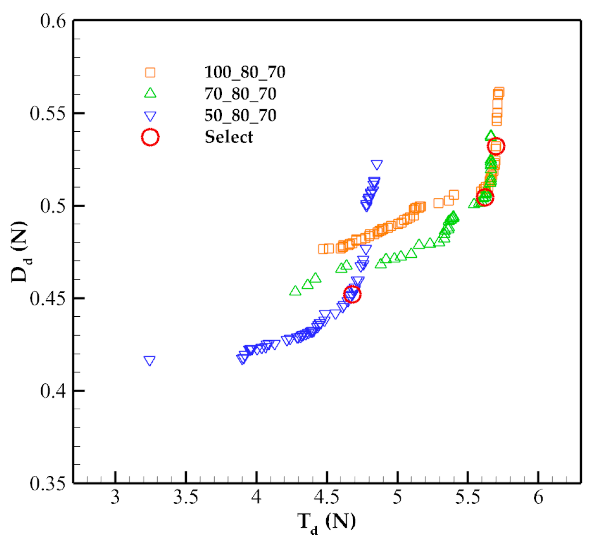
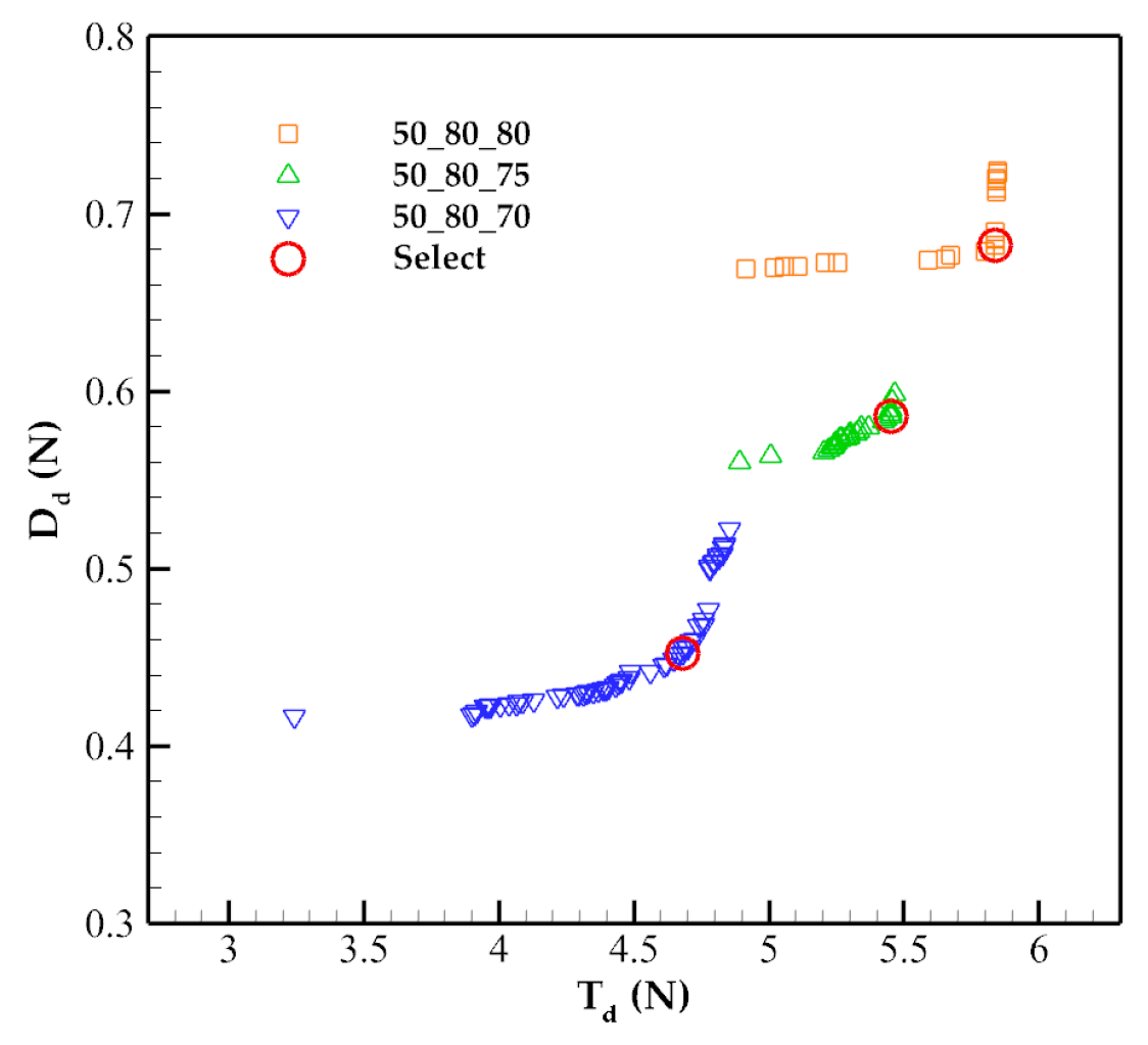
Figure 23.
Pareto front of the inlet of different lengths.
Figure 23.
Pareto front of the inlet of different lengths.
Figure 24.
Pareto front of the inlet of different heights.
Figure 24.
Pareto front of the inlet of different heights.
Figure 25.
Duct profile of the inlet of different lengths.
Figure 25.
Duct profile of the inlet of different lengths.
Figure 26.
Duct profile of the inlet of different heights.
Figure 26.
Duct profile of the inlet of different heights.
Figure 27.
Comparison of the velocity image of different optimization results of different inlets in hover flight: (a) 50_80_70; (b) 100_80_70; (c) 50_80_80.
Figure 27.
Comparison of the velocity image of different optimization results of different inlets in hover flight: (a) 50_80_70; (b) 100_80_70; (c) 50_80_80.
Figure 28.
Comparison of the pressure image of different optimization results of different inlets in hover flight: (a) 50_80_70; (b) 100_80_70; (c) 50_80_80.
Figure 28.
Comparison of the pressure image of different optimization results of different inlets in hover flight: (a) 50_80_70; (b) 100_80_70; (c) 50_80_80.
Figure 29.
Comparison of the total pressure image at the entrance of the blade section of different inlets in hover flight: (a) 50_80_70; (b) 100_80_70; (c) 50_80_80.
Figure 29.
Comparison of the total pressure image at the entrance of the blade section of different inlets in hover flight: (a) 50_80_70; (b) 100_80_70; (c) 50_80_80.
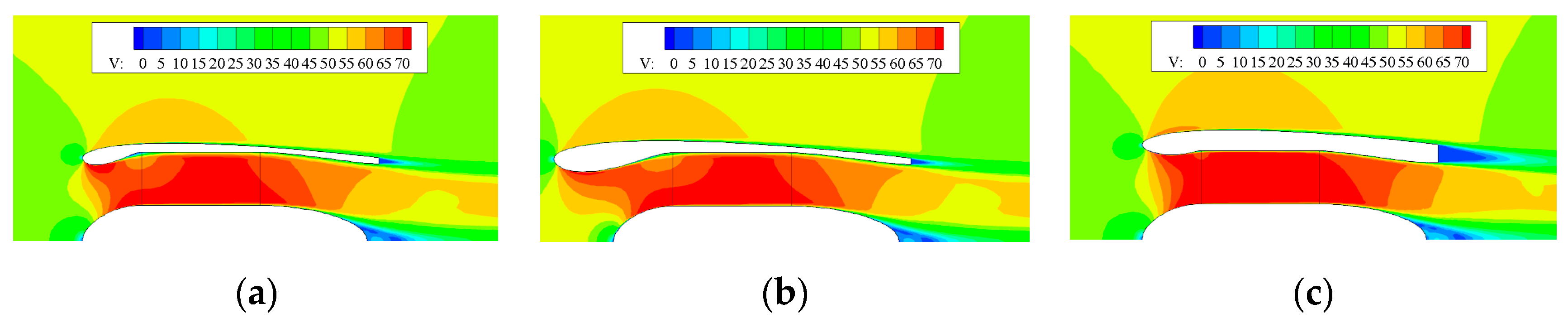
Figure 30.
Comparison of the velocity image of different optimization results of different inlets in cruise flight: (a) 50_80_70; (b) 100_80_70; (c) 50_80_80.
Figure 30.
Comparison of the velocity image of different optimization results of different inlets in cruise flight: (a) 50_80_70; (b) 100_80_70; (c) 50_80_80.
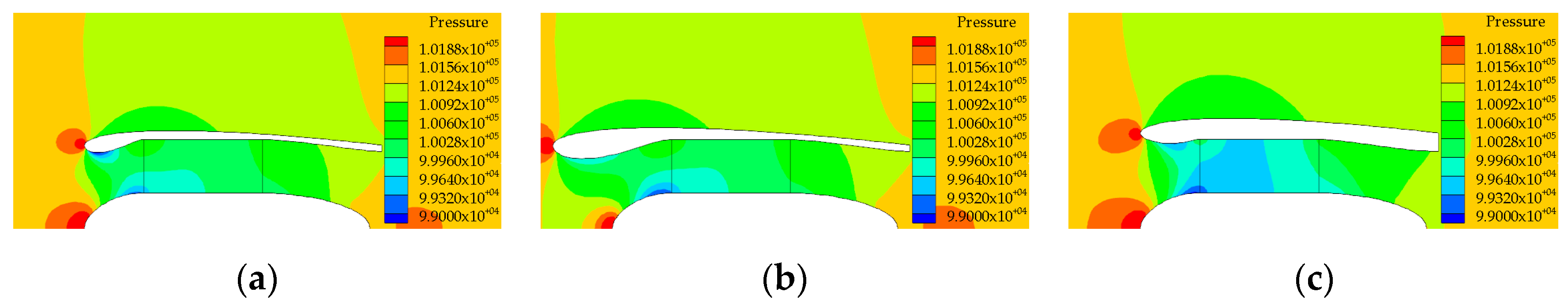
Figure 31.
Comparison of the pressure image of different optimization results of different inlets in cruise flight: (a) 50_80_70; (b) 100_80_70; (c) 50_80_80.
Figure 31.
Comparison of the pressure image of different optimization results of different inlets in cruise flight: (a) 50_80_70; (b) 100_80_70; (c) 50_80_80.
Figure 32.
Schematic diagram of the ducted fan unit.
Figure 32.
Schematic diagram of the ducted fan unit.
Figure 33.
Schematic diagram of the relative position between the ducted fan and induced wing.
Figure 33.
Schematic diagram of the relative position between the ducted fan and induced wing.
Figure 34.
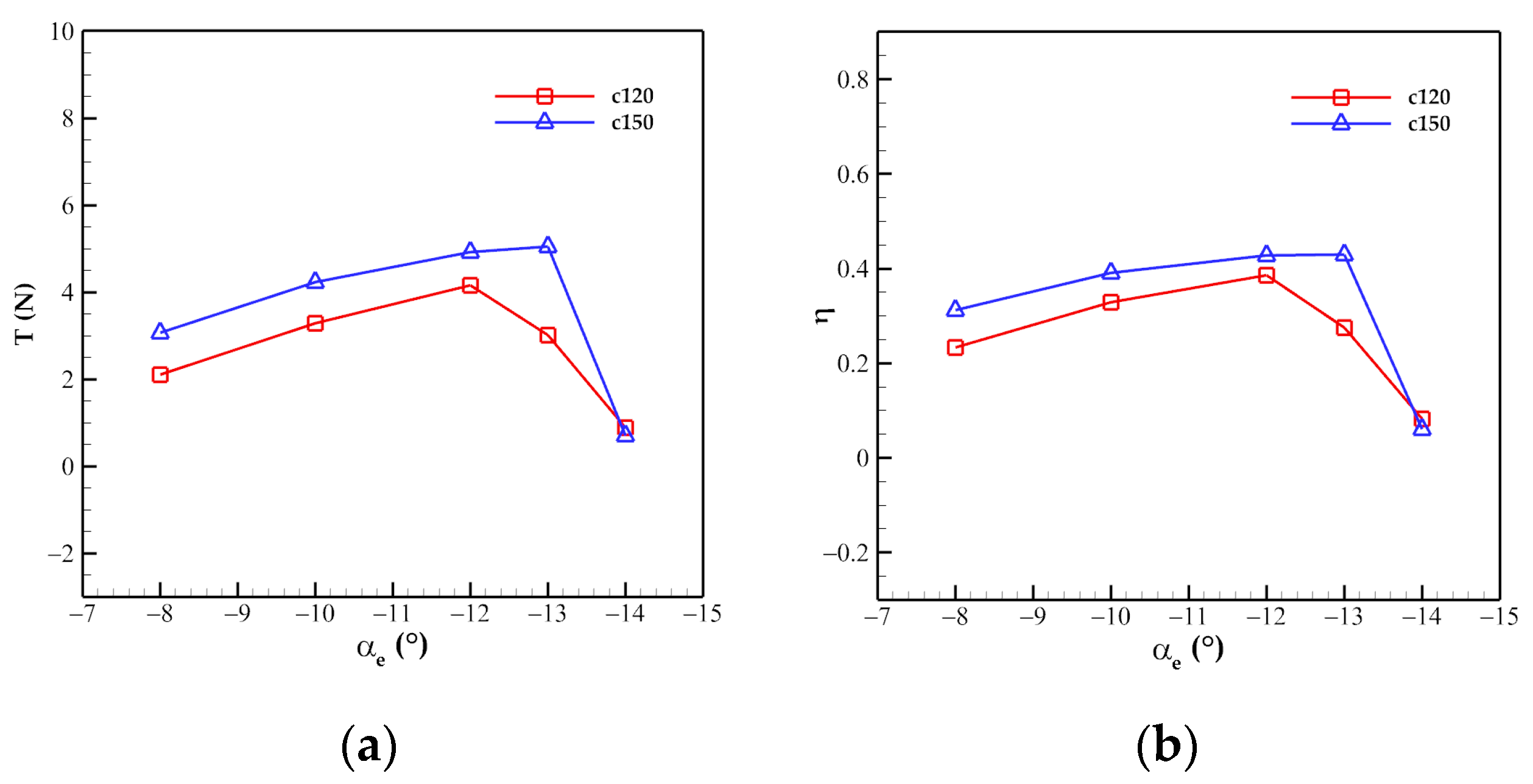
Comparison of the cruise performance of the distributed ducted fan system with different deflection angles of the induced wing at Ω = 8500 r/min: (a) Thrust; (b) Efficiency.
Figure 34.
Comparison of the cruise performance of the distributed ducted fan system with different deflection angles of the induced wing at Ω = 8500 r/min: (a) Thrust; (b) Efficiency.
Figure 35.
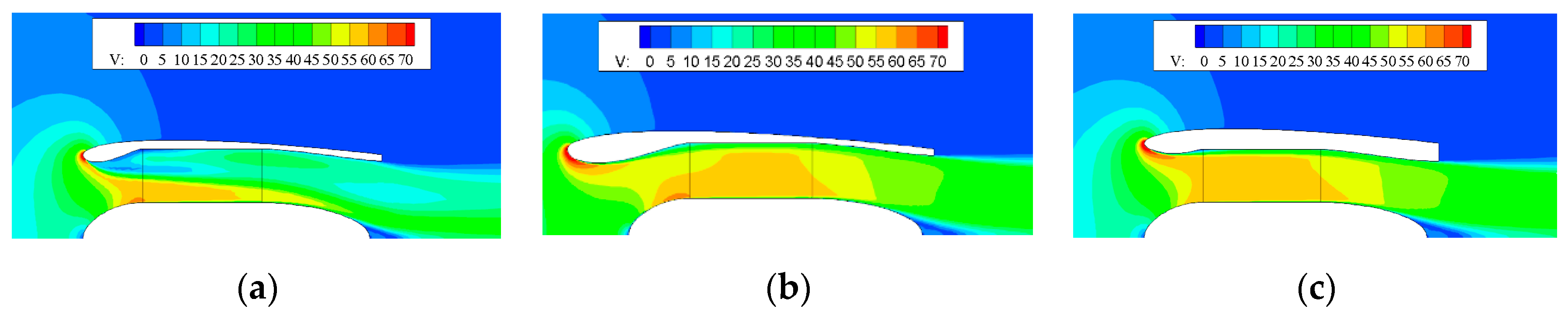
Comparison of sectional velocity image of the distributed ducted fan system with −12° deflection angle of the induced wing with different chord lengths: (a) 120 mm; (b) 150 mm.
Figure 35.
Comparison of sectional velocity image of the distributed ducted fan system with −12° deflection angle of the induced wing with different chord lengths: (a) 120 mm; (b) 150 mm.
Figure 36.
Comparison of the wake of the distributed ducted fan system with and without the induced wing in hover flight: (a) Without the induced wing; (b) With the induced wing.
Figure 36.
Comparison of the wake of the distributed ducted fan system with and without the induced wing in hover flight: (a) Without the induced wing; (b) With the induced wing.
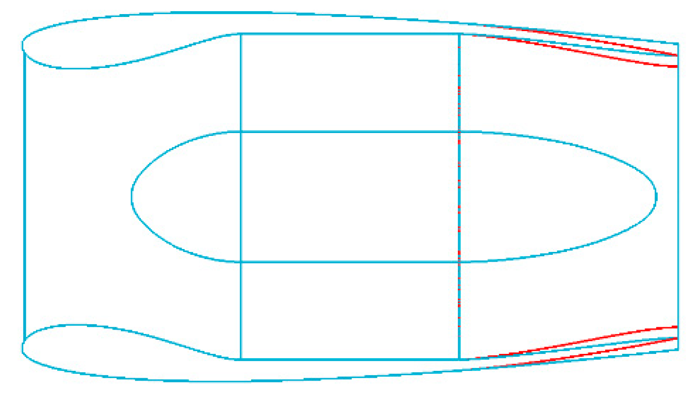
Figure 37.
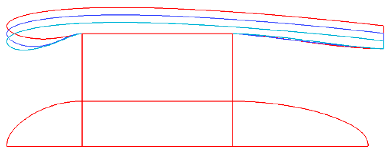
Comparison of duct profile of the distributed duct fan system before and after the improvement.
Figure 37.
Comparison of duct profile of the distributed duct fan system before and after the improvement.
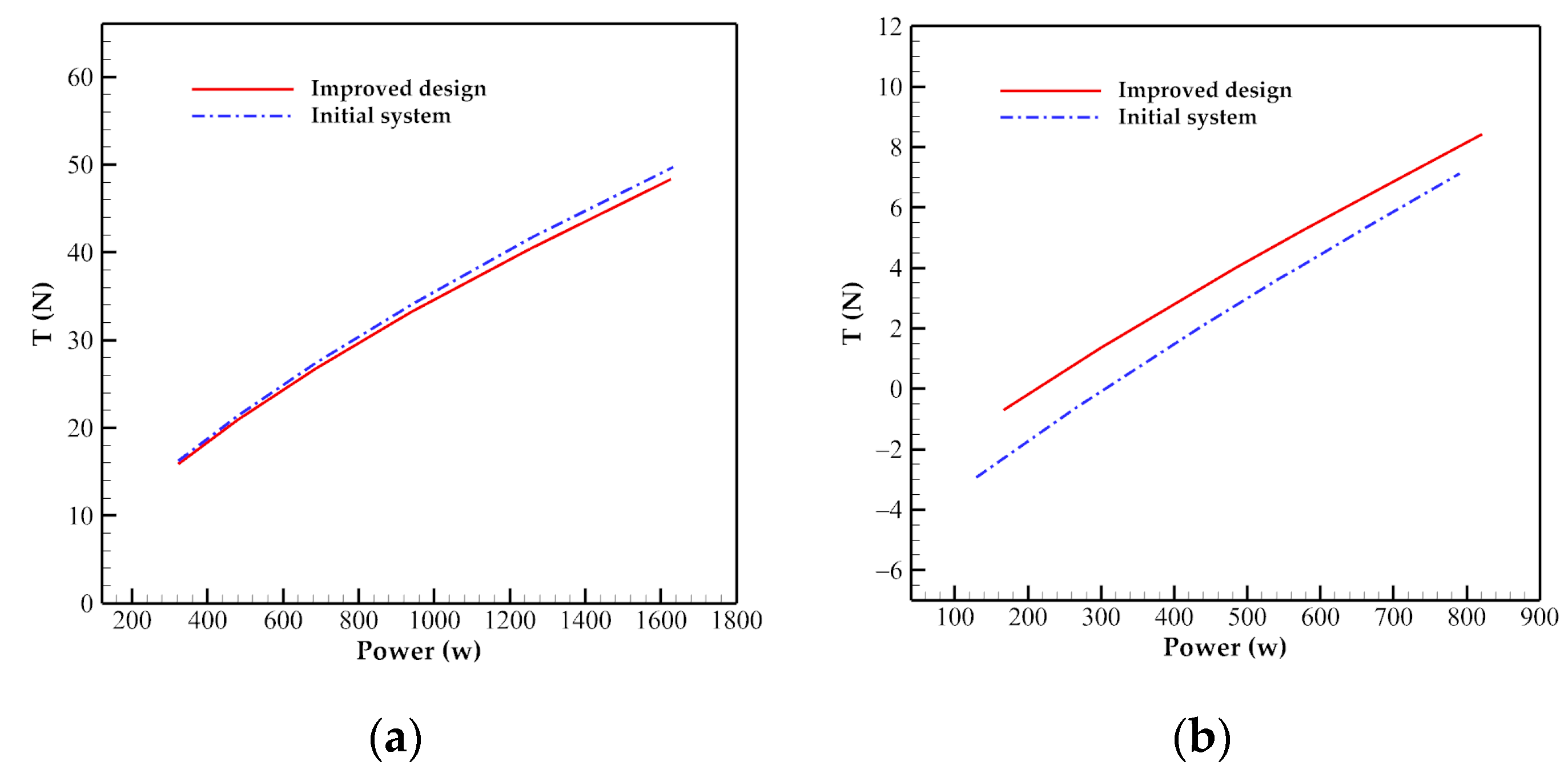
Figure 38.
Comparison of the cruise performance of the distributed ducted fan system with different deflection angles of the induced wing before and after the improvement at Ω = 8500 r/min: (a) Thrust; (b) Efficiency.
Figure 38.
Comparison of the cruise performance of the distributed ducted fan system with different deflection angles of the induced wing before and after the improvement at Ω = 8500 r/min: (a) Thrust; (b) Efficiency.
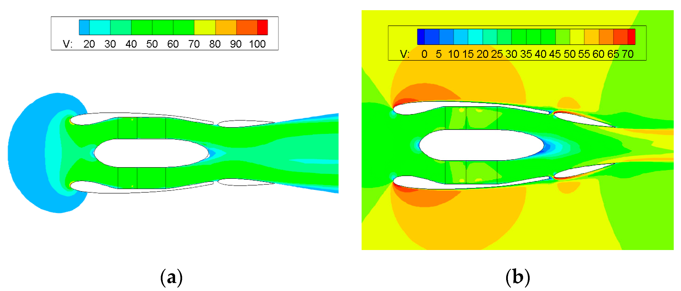
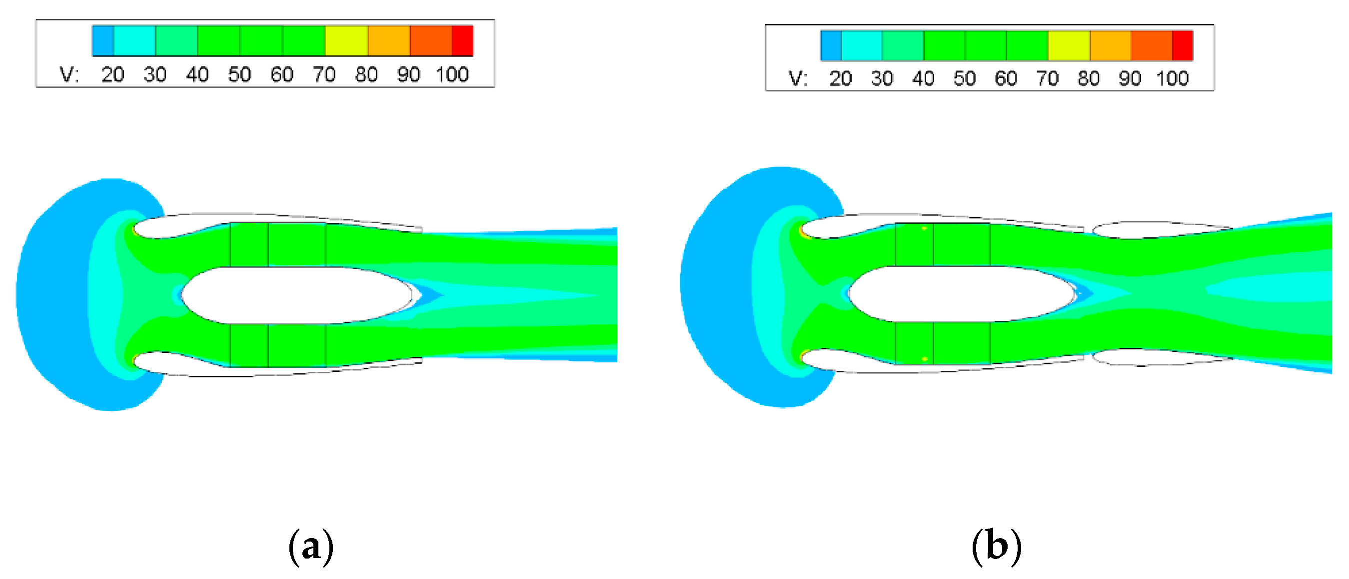
Figure 39.
Sectional velocity image of the improved distributed ducted fan system in two flight phases: (a) Hover; (b) Cruise.
Figure 39.
Sectional velocity image of the improved distributed ducted fan system in two flight phases: (a) Hover; (b) Cruise.
Figure 40.
Hover and cruise performance of the improved distributed ducted fan system: (a) Hover; (b) Cruise.
Figure 40.
Hover and cruise performance of the improved distributed ducted fan system: (a) Hover; (b) Cruise.
Table 1.
Characteristic comparison of different methods at Ω = 10,500 r/min.
Table 1.
Characteristic comparison of different methods at Ω = 10,500 r/min.
| Method | Tp (N) | Td (N·m) | T (N) | Error | Time (h) |
|---|
| EXP | - | - | 32.116 | - | - |
| MRF | 15.321 | 18.404 | 33.725 | 5.001% | 1.8 |
| MSM | 15.321 | 19.984 | 35.305 | 9.930% | 0.2 |
Table 2.
Hover performance of the distributed ducted fan unit.
Table 2.
Hover performance of the distributed ducted fan unit.
| αe (deg) | Ω (rpm) | T (N) | Tr (N) | Qr (N·m) | Ts (N) | Qs (N·m) | pl (kg·kw−1) |
|---|
| 3 | 10,850 | 40.369 | 16.195 | 1.061 | 2.524 | 1.072 | 3.349 |
Table 3.
Cruise performance of the distributed ducted fan unit.
Table 3.
Cruise performance of the distributed ducted fan unit.
| αe (deg) | Ω (rpm) | T (N) | Tr (N) | Qr (N·m) | Ts (N) | Qs (N·m) | η |
|---|
| −5 | 8610 | 3.998 | 8.778 | 0.631 | 0.920 | 0.642 | 35.136% |
Table 4.
Comparison of different optimization results of different inlets in hover flight.
Table 4.
Comparison of different optimization results of different inlets in hover flight.
| Result | Td (N) | Df (N) |
|---|
| 100_80_70 | 5.702 | 0.258 |
| 70_80_70 | 5.621 | 0.239 |
| 50_80_70 | 4.683 | 0.243 |
| 50_80_75 | 5.423 | 0.241 |
| 50_80_80 | 5.837 | 0.240 |
Table 5.
Comparison of different optimization results of different inlets in cruise flight.
Table 5.
Comparison of different optimization results of different inlets in cruise flight.
| Result | Dd (N) | Df (N) |
|---|
| 100_80_70 | 0.532 | 0.635 |
| 70_80_70 | 0.504 | 0.597 |
| 50_80_70 | 0.452 | 0.565 |
| 50_80_75 | 0.586 | 0.590 |
| 50_80_80 | 0.682 | 0.613 |
Table 6.
Comparison of the hover performance of the ducted fan unit.
Table 6.
Comparison of the hover performance of the ducted fan unit.
| Configuration | Ω (rpm) | T (N) | Tr (N) | Qr (N·m) | Ts (N) | Qs (N·m) | pl (kg·kw−1) |
|---|
| Initial system | 10,850 | 40.369 | 16.195 | 1.061 | 2.524 | 1.072 | 3.349 |
| Design | 11,000 | 40.198 | 17.518 | 1.100 | 3.001 | 1.091 | 3.172 |
Table 7.
Cruise performance of the designed distributed ducted fan system.
Table 7.
Cruise performance of the designed distributed ducted fan system.
| Configuration | Ω (rpm) | T (N) | Tr (N) | Qr (N·m) | Ts (N) | Qs (N·m) | η |
|---|
| Initial system | 8610 | 3.998 | 8.778 | 0.631 | 0.920 | 0.642 | 35.136% |
| Design | 8180 | 3.994 | 8.662 | 0.593 | 1.118 | 0.601 | 39.313% |
Table 8.
Comparison of the hover performance of the distributed ducted fan system with different deflection angles of the induced wing.
Table 8.
Comparison of the hover performance of the distributed ducted fan system with different deflection angles of the induced wing.
| αe (deg) | Ω (rpm) | T (N) | Tr (N) | Qr (N·m) | Ts (N) | Qs (N·m) | pl (kg·kw−1) |
|---|
| 0 | 11,000 | 40.068 | 16.408 | 1.087 | 2.425 | 1.096 | 3.200 |
| 1 | 11,000 | 40.347 | 16.288 | 1.083 | 2.392 | 1.097 | 3.234 |
| 2 | 11,000 | 39.623 | 16.201 | 1.082 | 2.343 | 1.096 | 3.179 |
Table 9.
Comparison of the hover performance of the distributed ducted fan system with different deflection angles of the induced wing after the improvement.
Table 9.
Comparison of the hover performance of the distributed ducted fan system with different deflection angles of the induced wing after the improvement.
| αe (deg) | Ω (rpm) | T (N) | Tr (N) | Qr (N·m) | Ts (N) | Qs (N·m) | pl (kg·kw−1) |
|---|
| 0 | 11,000 | 40.422 | 16.775 | 1.093 | 2.582 | 1.097 | 3.211 |
| 1 | 11,000 | 40.447 | 16.589 | 1.090 | 2.497 | 1.097 | 3.221 |
| 2 | 11,000 | 40.420 | 16.482 | 1.088 | 2.432 | 1.096 | 3.225 |
| 3 | 11,000 | 40.267 | 16.419 | 1.087 | 2.410 | 1.095 | 3.216 |
Table 10.
Comparison of the hover performance of different distributed ducted fan systems.
Table 10.
Comparison of the hover performance of different distributed ducted fan systems.
| Configuration | Ω (rpm) | T (N) | Tr (N) | Qr (N·m) | Ts (N) | Qs (N·m) | pl (kg·kw−1) |
|---|
| Initial system | 10,850 | 40.369 | 16.195 | 1.061 | 2.524 | 1.072 | 3.349 |
| Design | 11,000 | 40.347 | 16.288 | 1.083 | 2.392 | 1.097 | 3.234 |
| Improved design | 11,000 | 40.420 | 16.482 | 1.088 | 2.432 | 1.096 | 3.225 |
Table 11.
Comparison of the cruise performance of different distributed ducted fan systems.
Table 11.
Comparison of the cruise performance of different distributed ducted fan systems.
| Configuration | Ω (rpm) | T (N) | Tr (N) | Qr (N·m) | Ts (N) | Qs (N·m) | η |
|---|
| Initial system | 8610 | 3.998 | 8.778 | 0.631 | 0.920 | 0.642 | 35.136% |
| Design | 8180 | 3.994 | 8.662 | 0.593 | 1.118 | 0.601 | 39.313% |
| Improved design | 8050 | 3.991 | 8.399 | 0.574 | 1.085 | 0.580 | 41.240% |


