
Separation Reliability Analysis for the Low-Shock Separation Nut with Mechanism Motion Failure Mode


Abstract
:1. Introduction
2. Separation Simulation Model of the Separation Nut Mechanism
2.1. Basic Structure and Working Principle
2.2. Simulation Model of the Mechanism Separation
2.2.1. Combustion Model
2.2.2. Motion Modelling of the Separation Mechanism
- (1)
- Inner sleeve separation model
- (2)
- Piston separation model
- (3)
- Nut flap separation model
3. Separation Reliability Modelling of the Separation Nut Mechanism
3.1. Separation Limit State Function of the Separation Nut Mechanism
3.2. Kriging Surrogate Model
3.3. Reliability and Sensitivity Analysis
4. Implementation of the Reliability Simulation
5. Reliability and Sensitivity Analysis Results
6. Conclusions
Author Contributions
Funding
Institutional Review Board Statement
Informed Consent Statement
Data Availability Statement
Conflicts of Interest
References
- Benedetti, M.D.; Garofalo, G.; Zumpano, M.; Barboni, R. On the damping effect due to bolted junctions in space structures subjected to pyro-shock. Acta Astronaut. 2007, 60, 947–956. [Google Scholar] [CrossRef]
- Bement, L.J.; Schimmel, M.L. A Manual for Pyrotechnic Design, Development and Qualification; Report No. NASA TM-110172; NASA Langley Research Center: Hampton, VA, USA, 1995.
- Brauer, K.O. Handbook of Pyrotechnics; Chemical Publishing Co.: New York, NY, USA, 1974. [Google Scholar]
- Lee, J.; Hwang, D.H.; Jang, J.K.; Kim, D.J.; Lee, Y.; Lee, J.R.; Han, J.H. Pyroshock prediction of ridge-cut explosive bolts using hydrocodes. Shock. Vib. 2016, 2016, 14. [Google Scholar] [CrossRef]
- Wang, X.; Qin, Z.; Ding, J.; Chu, F. Finite element modeling and pyroshock response analysis of separation nuts. Aerosp. Sci. Technol. 2017, 68, 380–390. [Google Scholar] [CrossRef]
- Zhao, H.; Liu, W.; Ding, J.; Sun, Y.; Li, X.; Liu, Y. Numerical study on separation shock characteristics of pyrotechnic separation nuts. Acta Astronaut. 2018, 151, 893–903. [Google Scholar] [CrossRef]
- Woo, J.; Cha, S.W.; Cho, J.Y.; Kim, J.H.; Roh, T.; Jang, S.G.; Lee, H.-N.; Yang, H.W. Prediction of pyroshock-reduced separation nut behaviors. J. Propuls. Power 2018, 34, 1240–1255. [Google Scholar] [CrossRef]
- Zhang, H.; Liu, T.; Li, C.; Xiang, S.; Zhang, Q. Numerical simulation of pyrotechnic shock environment concerning pyroshock separation nuts of spacecraft. Spacecr. Environ. 2014, 31, 363–368. [Google Scholar]
- Lee, J.; Han, J.-H.; Lee, Y.; Lee, H. A Parametric Study of Ridge-cut Explosive Bolts using Hydrocodes. Int. J. Aeronaut. Space Sci. 2015, 16, 50–63. [Google Scholar] [CrossRef] [Green Version]
- Lee, J.; Han, J.-H.; Lee, Y.; Lee, H. Separation characteristics study of ridge-cut explosive bolts. Aerosp. Sci. Technol. 2014, 39, 153–168. [Google Scholar] [CrossRef]
- Huang, X.; Chen, J.; Zhu, H. Assessing small failure probabilities by AK–SS: An active learning method combining Kriging and Subset Simulation. Struct. Saf. 2016, 59, 86–95. [Google Scholar] [CrossRef]
- Bucher, C.; Bourgund, U. A fast and efficient response surface approach for structural reliability problems. Struct. Saf. 1990, 7, 57–66. [Google Scholar] [CrossRef]
- Sofi, A.; Muscolino, G.; Giunta, F. Propagation of uncertain structural properties described by imprecise Probability Density Functions via response surface method. Probabilistic Eng. Mech. 2020, 60, 103020. [Google Scholar] [CrossRef]
- Dai, H.; Zhang, H.; Wang, W.; Xue, G. Structural reliability assessment by local approximation of limit state functions using adaptive Markov chain simulation and support vector regression. Comput. Aided Civ. Inf. 2012, 27, 676–686. [Google Scholar] [CrossRef]
- Xiao, N.; Yuan, K.; Zhou, C. Adaptive kriging-based efficient reliability method for structural systems with multiple failure modes and mixed variables. Comput. Methods Appl. Mech. Eng. 2020, 359, 112–649. [Google Scholar] [CrossRef]
- Hurtado, J.E.; Alvarez, D.A. Neural-network-based reliability analysis: A comparative study. Comput. Methods Appl. Mech. Eng. 2001, 191, 113–132. [Google Scholar] [CrossRef]
- Gong, Q.; Zhang, J.; Tan, C.; Wang, C. Neural Networks Combined with Importance Sampling Techniques for Reliability Evaluation of Explosive Initiating Device. Chin. J. Aeronaut. 2012, 25, 208–215. [Google Scholar] [CrossRef] [Green Version]
- Bdour, T.; Guiffaut, C.; Reineix, A. Use of adaptive kriging metamodeling in reliability analysis of radiated susceptibility in coaxial shielded cables. IEEE Trans. Electromagn. Compat. 2016, 58, 95–102. [Google Scholar] [CrossRef]
- Yun, W.Y.; Lu, Z.Z.; Jiang, X. AK-SYSi: An improved adaptive Kriging model for system reliability analysis with multiple failure modes by refined U learning function. Struct. Multidiscip. Optim. 2019, 59, 263–278. [Google Scholar] [CrossRef]
- Hristov, P.O.; DiazDelaO, F.A.; Farooq, U.; Kubiak, K.J. Adaptive Gaussian process emulators for efficient reliability analysis. Appl. Math. Model. 2019, 71, 138–151. [Google Scholar] [CrossRef] [Green Version]
- Allaix, D.L.; Carbone, V.I. An improvement of the response surface method. Struct. Saf. 2011, 33, 165–172. [Google Scholar] [CrossRef]
- Zhang, M.-D.; Dai, H.-F.; Hu, B.-Q.; Chen, Q. Robust adaptive UKF based on SVR for inertial based integrated navigation. Def. Technol. 2020, 16, 846–855. [Google Scholar] [CrossRef]
- Echard, B.; Gayton, N.; Lemaire, M. AK-MCS: An active learning reliability method combining Kriging and Monte Carlo Simulation. Struct. Saf. 2011, 33, 145–154. [Google Scholar] [CrossRef]
- Zheng, P.J.; Wang, C.M.; Zong, Z.H.; Wang, L.Q. A new active learning method based on the learning function U of the AK-MCS reliability analysis method. Eng. Struct. 2017, 148, 185–194. [Google Scholar]
- Chen, W.D.; Xu, C.L.; Shi, Y.Q.; Ma, J.X.; Lu, S.Z. A hybrid Kriging-based reliability method for small failure probabilities. Reliab. Eng. Syst. Saf. 2019, 189, 31–41. [Google Scholar] [CrossRef]
- Keshtegar, B.; Nguyen-Thoi, T.; Truong, T.T.; Zhu, S.-P. Optimization of buckling load for laminated composite plates using adaptive Kriging-improved PSO: A novel hybrid intelligent method. Def. Technol. 2021, 17, 85–99. [Google Scholar] [CrossRef]
- Zhang, J.; Xiao, M.; Gao, L. An active learning reliability method combining Kriging constructed with exploration and exploitation of failure region and subset simulation. Reliab. Eng. Syst. Saf. 2019, 188, 90–102. [Google Scholar] [CrossRef]
- Jin, Z.M. Interior Ballistics of Guns Beijing; Beijing Institute of Technology Press: Beijing, China, 2004. [Google Scholar]
- Kubota, N. Propellants and Explosives: Thermochemical Aspects of Combustion; John Wiley & Sons: New York, NY, USA, 2015. [Google Scholar]
- Jang, S.-G.; Lee, H.-N.; Oh, J.-Y. Performance modeling of a pyrotechnically actuated pin puller. Int. J. Aeronaut. Space Sci. 2014, 15, 102–111. [Google Scholar] [CrossRef]
- Han, D.-H.; Sung, H.-G.; Jang, S.-G.; Ryu, B.-T. Parametric analysis and design optimization of a pyrotechnically actuated device. Int. J. Aeronaut. Space Sci. 2016, 17, 409–422. [Google Scholar] [CrossRef]
- Hwang, D.; Han, J.; Lee, J.; Lee, Y.J.; Kim, D. A mathematical model for the separation behavior of a split type low-shock separation bolt. Acta Astronaut. 2019, 164, 393–406. [Google Scholar] [CrossRef]
- Zhang, X.; Yan, X.; Yang, Q. Design and experimental validation of compact, quick-response shape memory alloy separation device. J. Mech. Des. 2013, 136, 011009.1–011009.9. [Google Scholar] [CrossRef]
- Gonthier, K.A.; Powers, J.M. Formulation, Predictions, and Sensitivity Analysis of a Pyrotechnically Actuated Pin Puller Model. J. Propuls. Power 1994, 10, 501–507. [Google Scholar] [CrossRef]
- Liu, Y.; Shi, Y.; Bai, X.; Liu, B. Stress–strength reliability analysis of multi-state system based on generalized survival signature. J. Comput. Appl. Math. 2018, 342, 274–291. [Google Scholar] [CrossRef]
- Ditlevsen, O.; Madsen, H.O. Structural Reliability Methods; John Wiley & Sons Ltd.: West Sussex, UK, 2007. [Google Scholar]
- Lophaven, S.; Nielsen, H.; SØndergaard, J. DACE a Matlab Kriging Toolbox; Technical University of Denmark: Copenhagen, Denmark, 2002. [Google Scholar]
- Cadini, F.; Santos, F.; Zio, E. An improved adaptive kriging-based importance technique for sampling multiple failure regions of low probability. Reliab. Eng. Syst. Saf. 2014, 131, 109–117. [Google Scholar] [CrossRef]
- Metropolis, N.; Ulam, S. The Monte Carlo method. J. Am. Stat. Assoc. 1949, 44, 335–341. [Google Scholar] [CrossRef] [PubMed]
- Hasofer, A.M.; Lind, N.C. An exact and invariant first order reliability format. J. Eng. Mech. ASCE 1974, 100, 111–121. [Google Scholar]
- Tan, X.; Shen, M.; Juang, C.H.; Zhang, Y. Modified robust geotechnical design approach based on the sensitivity of reliability index. Probabilistic Eng. Mech. 2020, 60, 103049.1–103049.5. [Google Scholar] [CrossRef]
- Cornell, C.A. A probability-based structural code. J. Am. Concr. Inst. 1969, 66, 974–985. [Google Scholar]
- Der Kiureghian, A.; Liu, P.L. Structural reliability under incomplete probability information. ASCE J. Eng. Mech. 1986, 112, 85–104. [Google Scholar] [CrossRef]
- Cheng, S.H.; Miao, J.M.; Wu, S.H. Investigating the effects of operational factors on PEMFC performance based on CFD simulations using a three-level full-factorial design. Pergamon 2012, 39, 250–260. [Google Scholar] [CrossRef]
- Harbitz, A. An efficient sampling method for probability of failure calculation. Struct. Saf. 1986, 3, 109–115. [Google Scholar] [CrossRef]
- Au, S.K.; Beck, J.L. Importance sampling in high dimensions. Struct. Saf. 2002, 25, 139–163. [Google Scholar] [CrossRef]


| Parameter | Value | Parameter | Value |
|---|---|---|---|
| Burn rate exponent (n) | 0.45 | Fraction of gases in product (ηg) | 0.095 |
| Non-ideal gas correction factor (ηp) | 0.9 | Covolume (αg) | 0.663 dm3 kg−1 |
| Specific heat ratio (k) | 1.09 | Starting arc thickness of CPN (el) | 488.6 μm |
| Explosion temperature (Tp) | 2691.85 K | Convective heat transfer coefficient (h) | 1050 W·m−2·K−1 |
| Shape characteristic parameter of CPN (χ) | 3 | Stefan–Boltzmann constant (σs) | 5.67 × 10⁻⁸ W·m−2·K−1 |
| Shape characteristic parameter of CPN (λ) | −1 | Net emissivity of the product (ξ) | 0.6 |
| Shape characteristic parameter of CPN (μ) | 1/3 | Absorption rate of the vessel wall (αw) | 0.6 |
| Density of the CPN particles (ρs) | 1.3 g cm−3 |
| Parameter | Value | Parameter | Value |
|---|---|---|---|
| Initial volume (V) | 1.10 × 10⁻⁶ m3 | Shear pin diameter (d) | 1.5 mm |
| Inner sleeve quality (msle) | 0.06126 kg | Supporting angle between piston and nut flap (α) | 15° |
| Compression area of inner sleeve (Asle) | 3.17 × 10⁻⁴ m2 | Side angle of screw thread (γ) | 15° |
| Piston quality (mpiston) | 13.74 × 10⁻³ kg | Supporting angle between end cap and nut flap (δ) | 15° |
| Compression area of piston (Apiston) | 1.68 × 10⁻⁴ m2 | Nut flap quality (mnut) | 9.57 × 10⁻³ kg |
| Preload (Fpre) | 12,000 N | Friction coefficient between inner sleeve and nut flap (μnut-sle) | 0.07 |
| Model | Type | Range/MPa | Linearity Error/% | Sensitivity/pC·MPa−1 | Working Temperature/℃ | Resonant Frequency/kHz | Shock Resistance/g | Overload/MPa |
|---|---|---|---|---|---|---|---|---|
| KISTLER601A | Piezoelectric | 25 | ±0.27 | 150 | −196–200 | 150 | 10,000 | 50 |
| First Peak Pressure/MPa | First Peak Pressure Time/ms | Second Peak Pressure/MPa | Second Peak Pressure Time/ms | |
|---|---|---|---|---|
| Experimental value | 8.47 | 0.51 | 5.46 | 4.38 |
| Simulation value | 8.58 | 0.52 | 5.27 | 4.51 |
| Relative error | 1.30% | 1.96% | 3.48% | 2.97% |
| Symbol | Mean | Std. | Distribution Type | Symbol | Mean | Std. | Distribution Type |
|---|---|---|---|---|---|---|---|
| d (mm) | 1.5 | 0.00667 | Normal | γ (°) | 15 | 0.03 | Normal |
| Asle (mm2) | 317 | 0.715 | Normal | n | 0.45 | 0.01 | Normal |
| Fpre (N) | 12,000 | 348 | Normal | ρ (g/cm3) | 1.3 | 0.074 | Normal |
| α (°) | 15 | 0.03 | Normal |
| Symbol | Mean | Std. | Distribution Type | Symbol | Mean | Std. | Distribution Type |
|---|---|---|---|---|---|---|---|
| Apiston (mm2) | 168 | 0.648 | Normal | γ (°) | 15 | 0.03 | Normal |
| Fpre (N) | 12,000 | 384 | Normal | δ (°) | 15 | 0.03 | Normal |
| n | 0.45 | 0.01 | Normal | ρ (g/cm3) | 1.3 | 0.074 | Normal |
| α (°) | 15 | 0.03 | Normal |
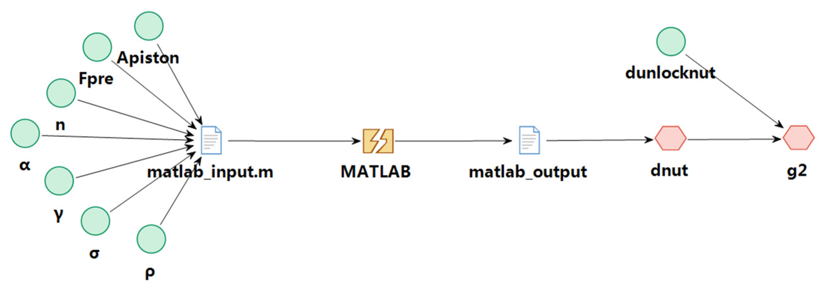
| Name/Inner Sleeve | Type | Name/Nut Flap | Type |
|---|---|---|---|
| d | Input variable | Apiston | Input variable |
| Asle | Input variable | Fpre | Input variable |
| Fpre | Input variable | n | Input variable |
| n | Input variable | α | Input variable |
| α | Input variable | γ | Input variable |
| γ | Input variable | δ | Input variable |
| ρ | Input variable | ρ | Input variable |
| dunlock-sle | Input variable | dunlock-nut | Input variable |
| MATLAB_input.m | MATLAB input script file | MATLAB_input.m | MATLAB input script file |
| MATLAB_output | MATLAB output file | MATLAB_output | MATLAB output file |
| MATLAB | MATLAB execution commands | MATLAB | MATLAB execution commands |
| dsle | Output variable | dnut | Output variable |
| g1 | Function of inner sleeve separation | g2 | Function of nut flap separation |
| Method | Rsle | β |
|---|---|---|
| Kriging Model + FORM | 0.99997 | 8.3284 |
| Kriging Model + MCS | 0.99998 | 8.3556 |
| Importance sampling (104 samples) | 0.99994 | 8.3748 |
| Method | Rnut | β |
|---|---|---|
| Kriging Model + FORM | 0.99668 | 1.4999 |
| Kriging Model + MCS | 0.99846 | 1.4234 |
| Importance sampling (104 samples) | 0.99546 | 1.4137 |
| Method | R | Relative Error (%) |
|---|---|---|
| Kriging Model + FORM | 0.99665 | 0.125 |
| Kriging Model + MCS | 0.99844 | 0.305 |
| Importance sampling(104 samples) | 0.99540 | NA |
Publisher’s Note: MDPI stays neutral with regard to jurisdictional claims in published maps and institutional affiliations. |
© 2022 by the authors. Licensee MDPI, Basel, Switzerland. This article is an open access article distributed under the terms and conditions of the Creative Commons Attribution (CC BY) license (https://creativecommons.org/licenses/by/4.0/).
Share and Cite
Niu, L.; Tu, H.; Dong, H.; Yan, N. Separation Reliability Analysis for the Low-Shock Separation Nut with Mechanism Motion Failure Mode. Aerospace 2022, 9, 156. https://doi.org/10.3390/aerospace9030156
Niu L, Tu H, Dong H, Yan N. Separation Reliability Analysis for the Low-Shock Separation Nut with Mechanism Motion Failure Mode. Aerospace. 2022; 9(3):156. https://doi.org/10.3390/aerospace9030156
Chicago/Turabian StyleNiu, Lei, Hongmao Tu, Haiping Dong, and Nan Yan. 2022. "Separation Reliability Analysis for the Low-Shock Separation Nut with Mechanism Motion Failure Mode" Aerospace 9, no. 3: 156. https://doi.org/10.3390/aerospace9030156
APA StyleNiu, L., Tu, H., Dong, H., & Yan, N. (2022). Separation Reliability Analysis for the Low-Shock Separation Nut with Mechanism Motion Failure Mode. Aerospace, 9(3), 156. https://doi.org/10.3390/aerospace9030156