1. Introduction
As agile small satellites have higher and higher requirements for attitude control accuracy, the flywheel is used as the actuator of the attitude control system [
1], and its control accuracy directly affects the attitude stability of the satellite [
2,
3]. The core component of the microsatellite attitude control flywheel is essentially a controllable motor that meets certain rotational inertia requirements. It provides driving power for the operation of the flywheel rotor, and the flywheel rotor provides effective rotational inertia to the outside world.
In modern high-precision attitude control flywheel systems, BLDC motors are often used as flywheel drive motors. A BLDC motor is very appropriate for a small satellite attitude control flywheel, due to its long life, high efficiency, and wide speed range [
4,
5]. However, the unique commutation method of the BLDC motor makes its speed and torque fluctuate greatly during operation, which has a great impact on the control accuracy of the flywheel [
6,
7].
In order to achieve accurate attitude control, it is very important to design a good motor control system. To reduce the speed pulsation of the BLDC motor for the attitude control flywheel, the traditional PID control strategy is often adopted in the BLDC motor speed control system [
8]. However, the traditional PID controller is not suitable for nonlinear uncertain systems [
9]. When the BLDC motor is subject to external disturbance or its load changes, the traditional PID control exposes the shortcomings of the signal processing: it is too simple, and the control parameters cannot be adjusted with the environment. To ensure the normal operation of the system, the PID parameters need to be adjusted continuously, which will result in very high energy consumption [
10].
Many pieces of research on the optimization method for high precision control of BLDC motors have been carried out in the last decades. These optimization methods involve intelligent control, nonlinear control, and other control methods, specifically fuzzy control [
11], neural network control [
12], and other advanced control methods. These optimization control methods effectively improve the dynamic and steady-state performance of the BLDC motor. Among them, fuzzy control is a control method based on fuzzy control theory, which has a good control effect on nonlinear systems with time-varying and uncertain parameters [
13]. The fuzzy PID controller has been widely applied to the BLDC motor system. However, once the fuzzy discourse domain of input and output variables is set, it cannot be adjusted in the whole control process [
14]. Therefore, if the fuzzy discourse domain is too large or too small, it can seriously affect the effect of control. However, in the actual application process, the input and output of the control system often have a large range. The fuzzy discourse domain of fuzzy PID control lacks online self-learning ability, resulting in the controller parameters cannot be self-adjusted, making it difficult to meet the control needs [
15].
In recent years, some researchers have tried to use intelligent control algorithms to optimize the fuzzy PID controller, given the weak ability to adjust the fuzzy discourse domain of fuzzy control methods. In [
16], particle swarm optimization has been used for optimizing the fuzzy PID control algorithm, and it was applied for the speed control of the BLDC motor. From the results, we can see that the particle swarm optimization algorithm has the advantage of a simple algorithm structure, and has achieved good results. However, it has the disadvantages of many parameters and low convergence accuracy. An ant colony optimization has been used to optimize fuzzy PID controller in [
17]. An ant colony algorithm has the advantage of low computational complexity, but the algorithm has many parameters, and the selection of parameters has a great impact on the optimization results of an ant colony algorithm. In [
18], optimization of the fuzzy proportional derivative integral controller design is carried out using bat optimization algorithms. Bat algorithms introduce frequency to control the flight speed, which speeds up the convergence of the algorithm, but it is easier to fall into local optimum. In [
19], a grey wolf algorithm optimization is designed for fuzzy PID controller. A grey wolf algorithm has the advantages of few parameters and strong optimization ability. However, the algorithm also has the defects of single population diversity and premature convergence. The whale optimization algorithm has been used to optimize fuzzy PID controller in [
20,
21]. The whale optimization algorithm has the advantage of fast convergence speed because of its simple algorithm structure, but its global contraction ability is weak and it is difficult to jump out of the local optimal solution.
The above optimization algorithms have effectively improved the dynamic performance of the control system and have been adopted by many researchers. However, some optimization algorithms have many parameters that are difficult to adjust, and the results are often not the best optimal solution, so they cannot achieve the best optimization effect. Therefore, a new optimization algorithm is adopted to improve the performance of the BLDC motor control system in this paper.
AEFA is a new meta-heuristic optimization algorithm proposed by Anita and Anupam Yadav in 2019 [
22]. Compared with other algorithms, it has the advantages of faster convergence speed and higher convergence accuracy [
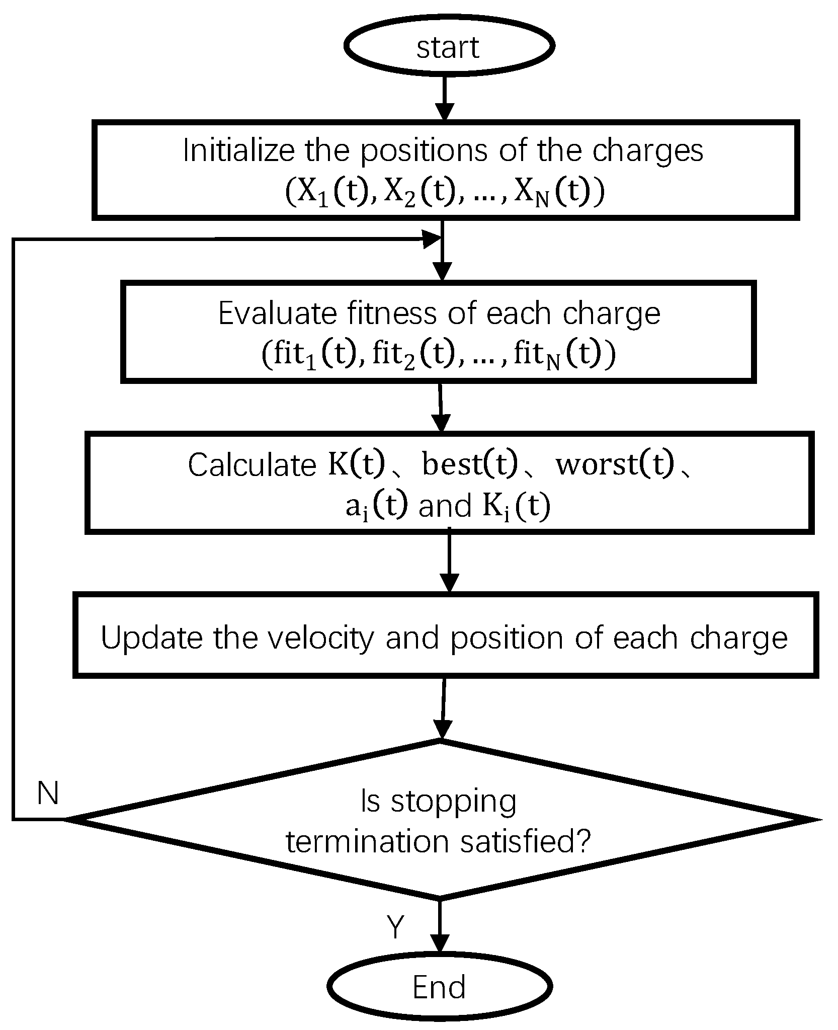
23]. In this algorithm, the charge is defined as a function of the fitness of the candidate solution and the overall fitness, the strength of which is measured by the amount of its charge. All charges can electrostatically attract or repel each other, so the charges move through the search space, and the positions of the charges correspond to the solution to the problem. At present, there is no research on using AEFA to optimize motor control parameters.
This paper presents a new fuzzy PID control method based on the AEFA for a BLDC motor. In the second part, we have established the mathematical model of the BLDC motor, and the speed control system using traditional PID control is designed. Moreover, a PID control strategy based on fuzzy control to optimize the speed control system of the BLDC motor is designed, aiming at the deficiency of non-adjustable control parameters in traditional PID control. In the third part, to improve the stability of the BLDC motor speed control system, a method of optimizing the fuzzy PID control based on the AEFA is further proposed, and the realization steps of optimizing the fuzzy PID control of the BLDC motor by AEFA are given. Finally, the effectiveness of the proposed control method is proved by comparing the proposed control with traditional PID control and fuzzy PID control through simulation experiments.
2. BLDC Motor Control System
2.1. Mathematical Model of BLDC Motor
The small satellite attitude control flywheel generally uses the BLDC motor driven by the AC supply from the three-phase inverter, which is designed using six switches with an appropriate sequence.
For the convenience of analysis, it is assumed that all the stator phase windings have equal resistance per phase and constant self and mutual inductances, the iron loss is negligible, motor flux is unsaturated and power semiconductor devices are ideal. It is supposed that at any instant only two-phase windings conduct current. The mathematical model of the BLDC motor can be established as follows:
where
,
,
represent three phase voltages (V),
,
,
represent three phase back emf (V),
,
,
represent three phase resistance (Ω),
,
,
represent three phase current (A),
,
,
represent the three phase armature of self inductance (H),
,
,
,
,
,
represent the three phase mutual inductances (H).
Determined by the structure of the motor, it can be assumed that the three-phase windings are symmetrical [
24]; there are:
Rearranging the Equation (1), we can obtain:
The torque equation in terms of phase back-emfs and phase currents is given by:
where
represents the angular velocity of BLDC motor
.
The equation of electromagnetic torque without load can be expressed as:
The equation of electromagnetic torque with load can be expressed as:
where
represents the load torque,
represents the friction coefficient
represents the moment of inertia
.
2.2. Control System of BLDC Motor Using Traditional PID Controller
In this paper, a simulation model of the BLDC motor control system is designed.
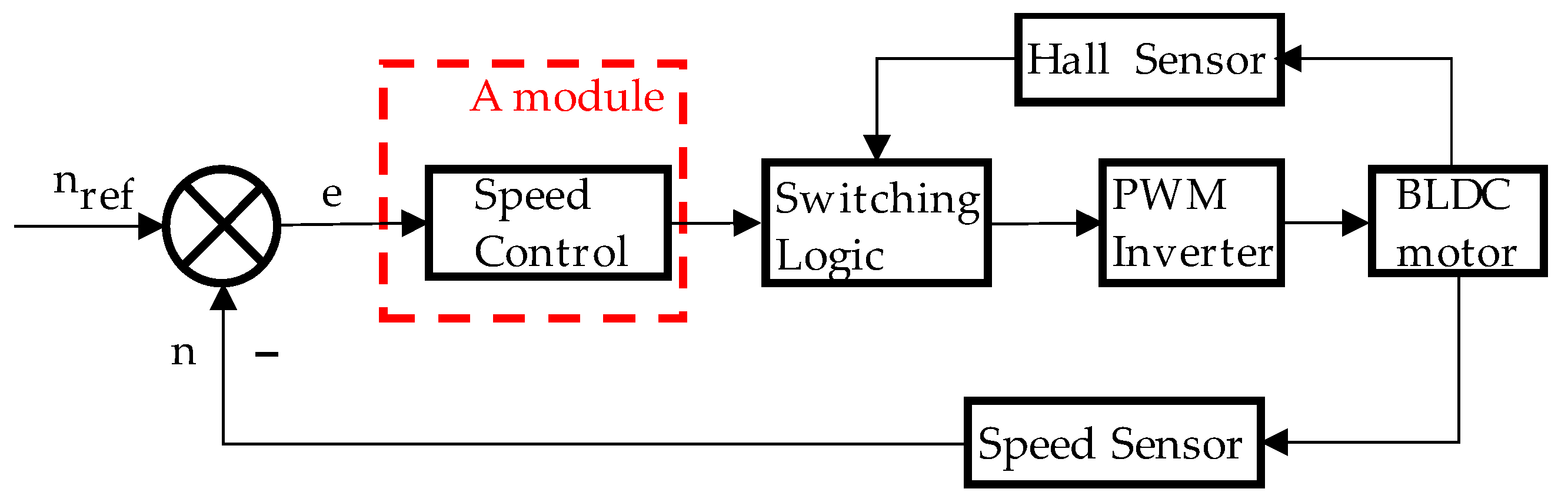
Figure 1 shows the block diagram of the BLDC motor control system [
25]. The system mainly consists of six modules, which include the speed regulation module (A module).
In this case, the hall sensor is used for obtaining the back electromotive force or rotor position of the BLDC motor. The inverting gate signal with the back electromotive force or rotor position of the BLDC motor can be synchronized by the switching logic module. The speed sensor is used to sense the actual speed of the rotor, and then it is compared with the reference speed to produce speed error. The speed error is used as the input of the speed controller. Then, the speed controller provides the control signals to the switching logic module and controls the BLDC motor by controlling the DC bus voltage.
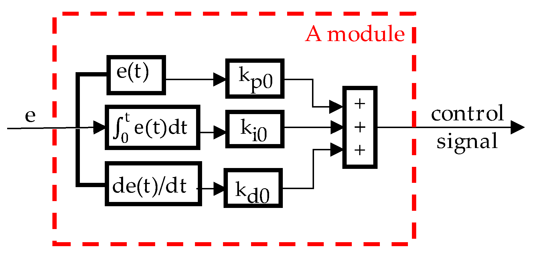
The block diagram of the speed regulation module controlled by traditional PID is shown in
Figure 2.
In this figure , , are the initial set value of the proportional gain value, integral gain value, and differential gain value, respectively, in the traditional PID control. The initial set value of the PID controller is determined according to experience, and remains unchanged during the optimization process.
The control output equation of the traditional PID controller is given by:
where
,
represents the current speed of the BLDC motor at the current moment t,
represents the reference speed of the BLDC motor at the current moment t, and
represents the error between the reference speed and the actual speed at the current moment t.
As shown in Equation (7), the traditional PID control is not a model-based control, because the , , are given, and the value remains unchanged during the operation of the BLDC motor system, which makes the traditional PID control simple and universal. However, it also has the disadvantages of being insensitive to model parameters and insensitive to changes in external parameters. During the actual operation of the BLDC motor, changes in its parameters and changes in loads often occur. At this point, when the traditional PID controller controls the BLDC motor, the speed fluctuation of the BLDC motor system will be largely due to the low control accuracy.
2.3. Control System of BLDC Motor Using Fuzzy PID Controller
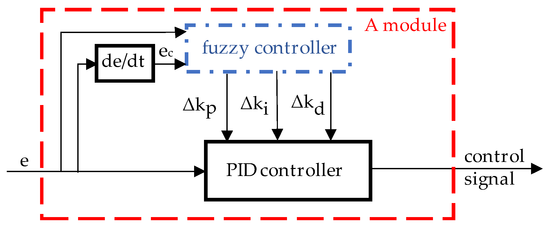
Fuzzy control makes up for the insufficiency of the fixed parameters of the traditional PID control and has a good control effect for the nonlinear system with time-varying and uncertain parameters. A two-dimensional fuzzy controller is introduced for the speed control system of the BLDC motor [
26]. The block diagram of the BLDC motor speed adjustment module using a fuzzy PID controller is shown in
Figure 3.
In the figure e represents the speed error, represents the speed error rate, and represent the changes of proportional gain, integral gain and differential gain after the fuzzy controller.
The control parameters after the fuzzy PID controller are shown in Equation (8):
Adding the control parameters after the fuzzy controller to the gain coefficient in the traditional PID controller can realize the optimization of the traditional PID controller. The BLDC motor speed control system becomes time-varying and can adjust the control parameters according to external disturbances, making the system more stable.
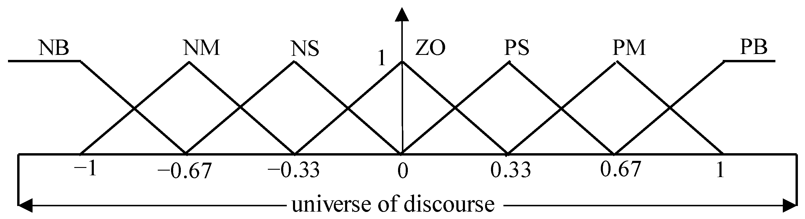
2.3.1. Fuzzification and Domain Setting of Fuzzy PID Controller
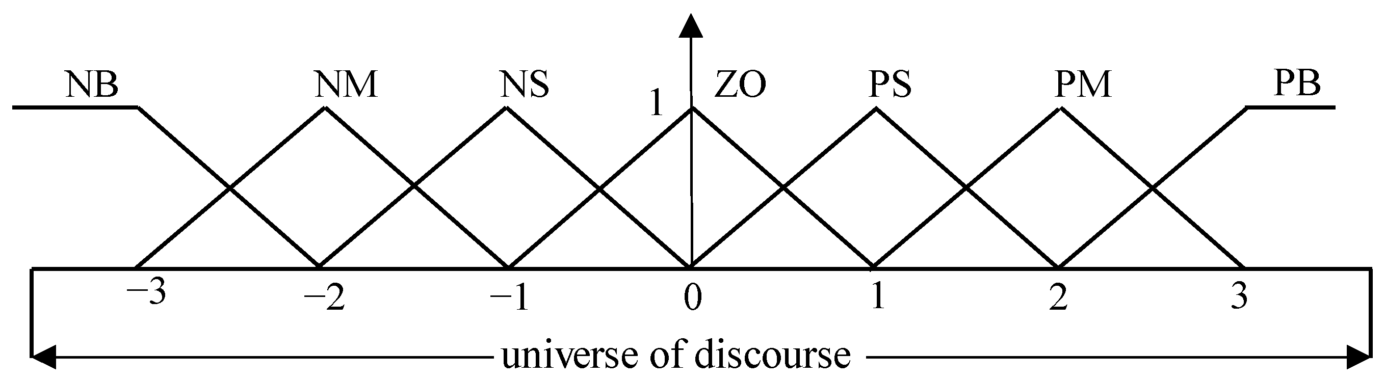
In this paper, the input and output fuzzy language variables of the speed control system of the BLDC motor are set to seven, namely NB, NM, NS, ZO, PS, PM, PB, which are negative large, negative medium, negative small, zero, and positive small, respectively. This can not only ensure the speed of fuzzy inference but also clearly describe the input and output variables. To ensure the reliable operation of the BLDC motor, this paper uses the trigonometric function as the membership function of the fuzzy controller variables, and the basic discourse domain of the input is set as [−3,3] and the basic discourse domain of the output is set as [−1,1], as shown in
Figure 4 and
Figure 5.
2.3.2. Establishment of the Fuzzy Control Rules
Fuzzy rules are the result of the combination of expert reasoning and a series of human experiences in the field of control. It is an important part of fuzzy control. In this paper, based on the debugging experience of the PID parameters of the experimental platform, the established fuzzy rules are shown in
Table 1,
Table 2 and
Table 3:
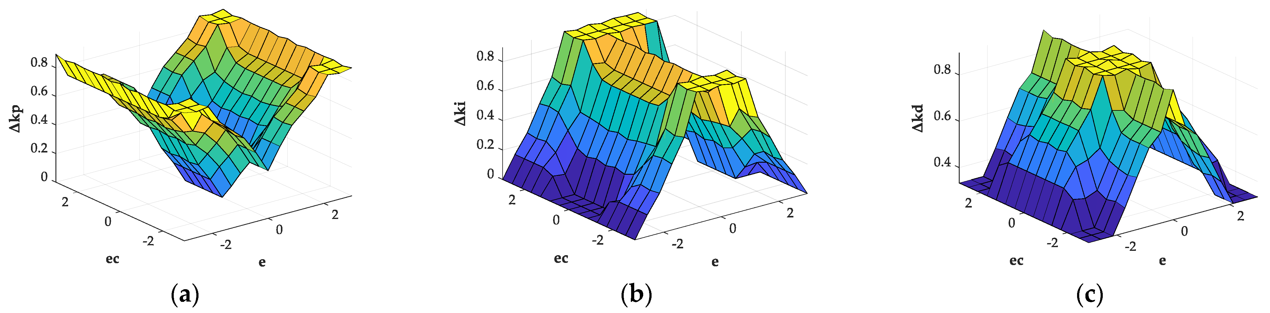
In the fuzzy rule editor, the inference method is the Mamdani method, and the area center method is used for de fuzzification. The three-output fuzzy PID control surface viewer with input and output membership functions is shown in
Figure 6.
Although the fuzzy PID controller makes an improvement, the disadvantage of the traditional PID control parameters remain unchanged. However, at present, for the fuzzy PID controller of the BLDC motor, the discourse domain and fuzzy rules of the input and output of the fuzzy controller adopt the method of the fixed value.
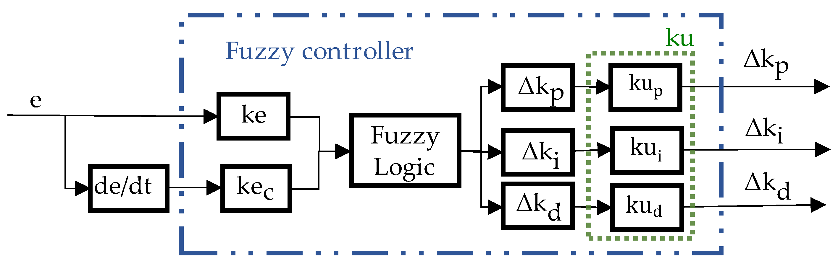
2.3.3. Design of the Fuzzy PID Controller
The fuzzy controller includes the input proportional factors
and
and the output proportional factor
. The input proportional factors and the output proportional factor are used to improve the control accuracy and enhance the online adjustment capability of the control system. The structure diagram of the fuzzy controller for the BLDC motor is shown in
Figure 7.
As shown in
Figure 7, the actual values of errors and their changes are fuzzified with
and
, respectively, and the errors and their changes are scaled to the scope of the fuzzy universe, and then through fuzzy logic the output of the fuzzy controller can be obtained. The output proportional factor
(
) can change the value of the output, which is equivalent to increasing the fuzzy control rules of the fuzzy controller, so that the precision of the fuzzy controller can be improved.
The input proportional factor is called the quantization factor. Assume that the basic domain of error is . It can be known from the above that the domain of a fuzzy subset taken by the error and the change of error is [−3,3]. Generally, the quantization factor of the error is calculated by and the quantization factor of the error change ratio is calculated by . The output proportional factor is called scale factor. In this paper, it is set that the value of scale factor in the non optimized fuzzy controller is . However, in many cases, this is not the best choice.
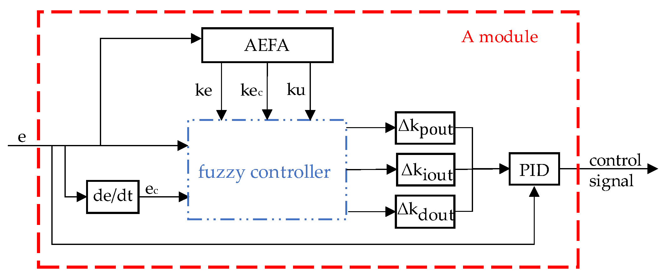
When the error of the speed control system changes in a large range, the fuzzy rule division will initially be rough, resulting in low control accuracy. Therefore, we can introduce an optimization algorithm to make the output proportional factors and the input proportional factors change with the input value to improve the accuracy of the BLDC motor.
4. Simulation Results and Discussion
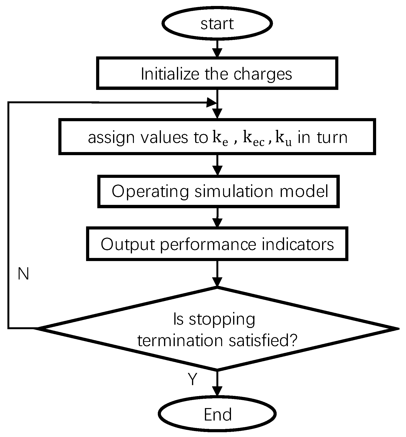
The effectiveness of the proposed fuzzy PID–AEFA controller has been tested by using the model of the BLDC motor. The model is developed in the Simulink of MATLAB R2021a. The numerical solution is obtained by the fourth order Runge–Kutta method, using a 10−4 s integration step. The AEFA gradually minimizes the objective function while finding the best parameters for the fuzzy PID controller. The program stops if the value of the objective function does not change significantly in successive iterations (that is, if the difference between the objective function values of two consecutive iterations is less than the pre-specified precision) or exceeds the maximum number of iterations. The maximum number of iterations is set at 20.
The following figures demonstrate the complex responses of the velocity variables with time. It is obvious that the velocity curve with time tends to have a steady state value under the three control methods.
Figure 11,
Figure 12 and
Figure 13 show the response speed with a PID controller, a fuzzy PID controller, and a fuzzy PID–AEFA controller. They are respectively denoted by PID, fuzzy and AEFA in the legend.
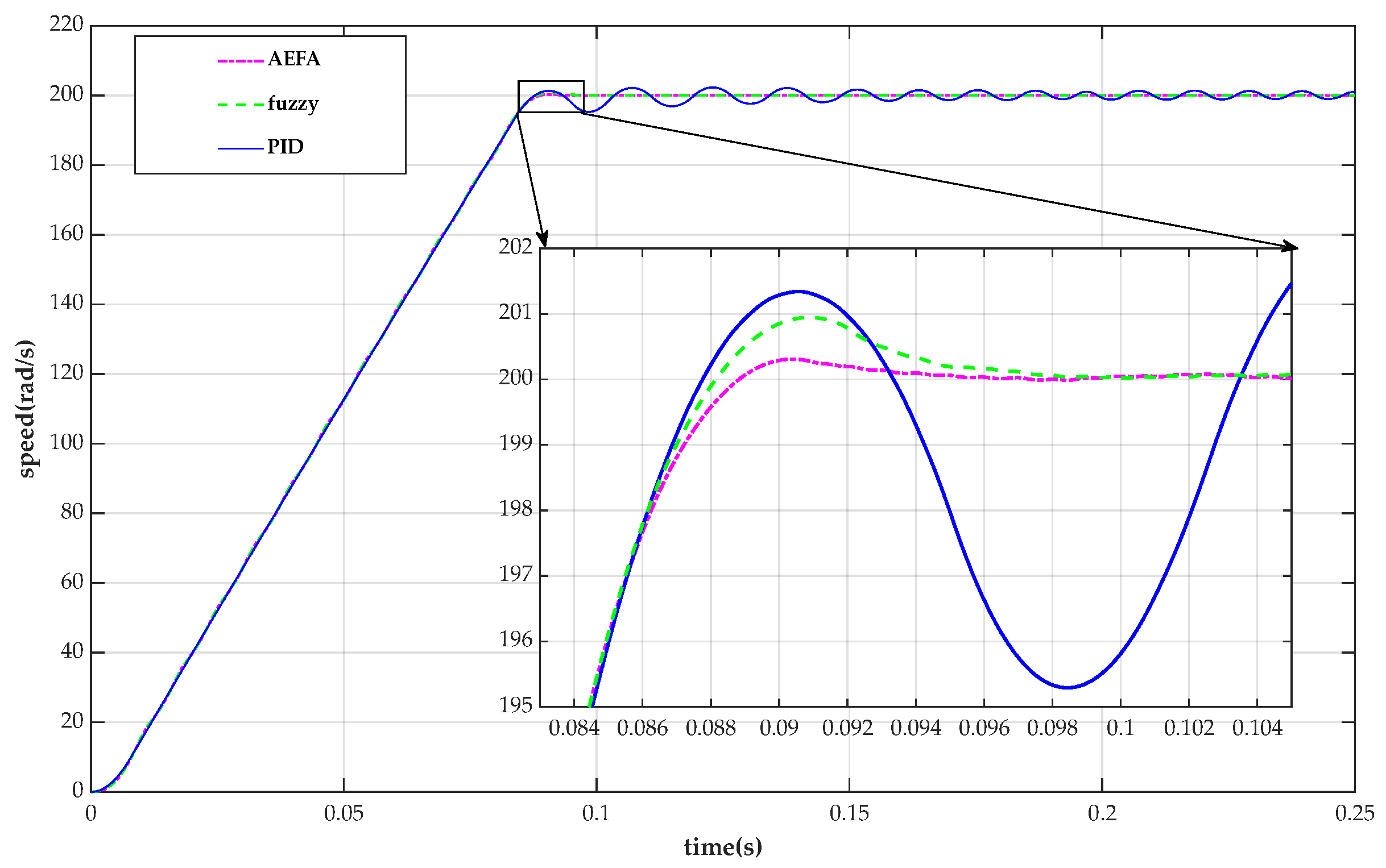
The speed response of the BLDC motor for three controllers under no-load condition is given in
Figure 11. It is apparent that the maximum overshoot due to the fuzzy PID–AEFA controller has the value close to 0. This shows that the fuzzy PID–AEFA control method has high performance relative to the other curves (small settling time and smallest overshoot).
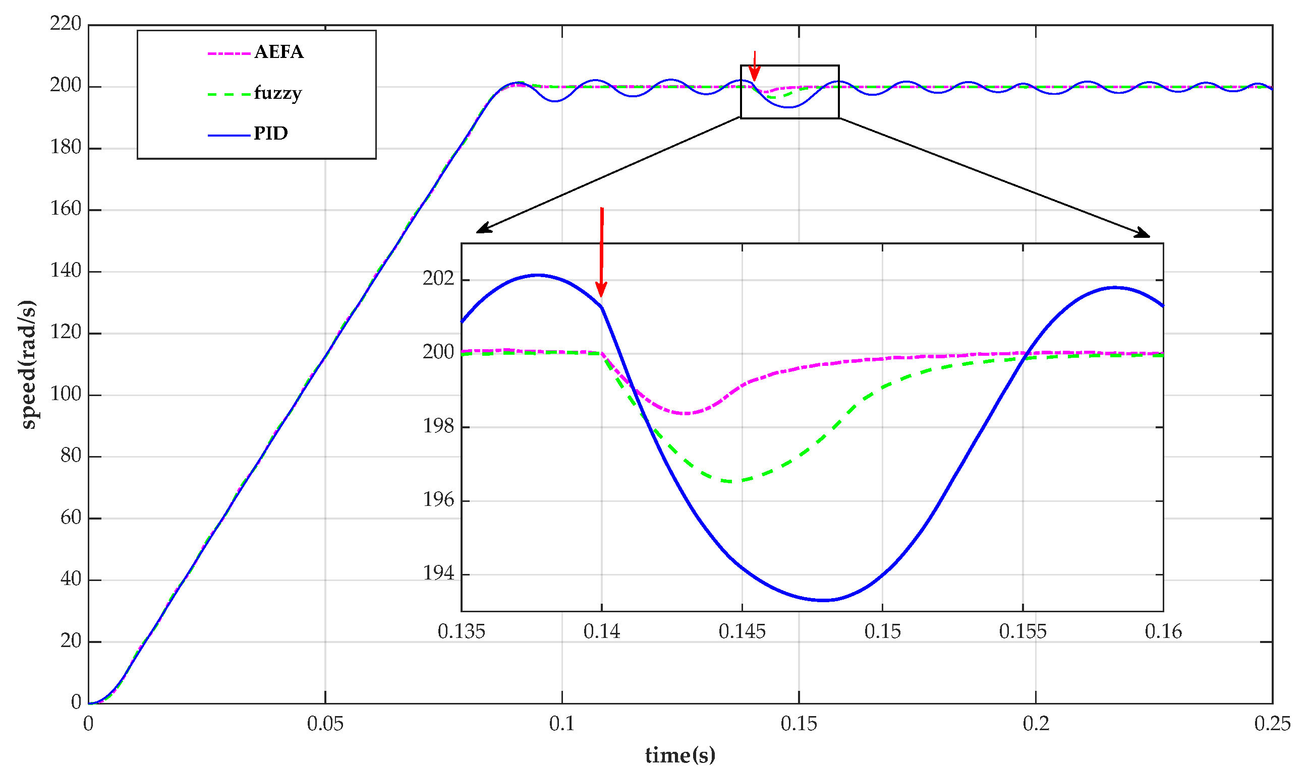
The speed response of the BLDC motor for three controllers under full-load condition is given in
Figure 12. In order to verify the effectiveness of the controller under actual working conditions, load disturbance is introduced, and the load changes from no-load to full-load at 0.14 s. It is apparent that the increase in load will cause a decrease in stability, but the decrease of the fuzzy PID–AEFA controller is the smallest. This shows that the fuzzy PID–AEFA controller reduces the speed fluctuation of the BLDC motor system when the load is added.
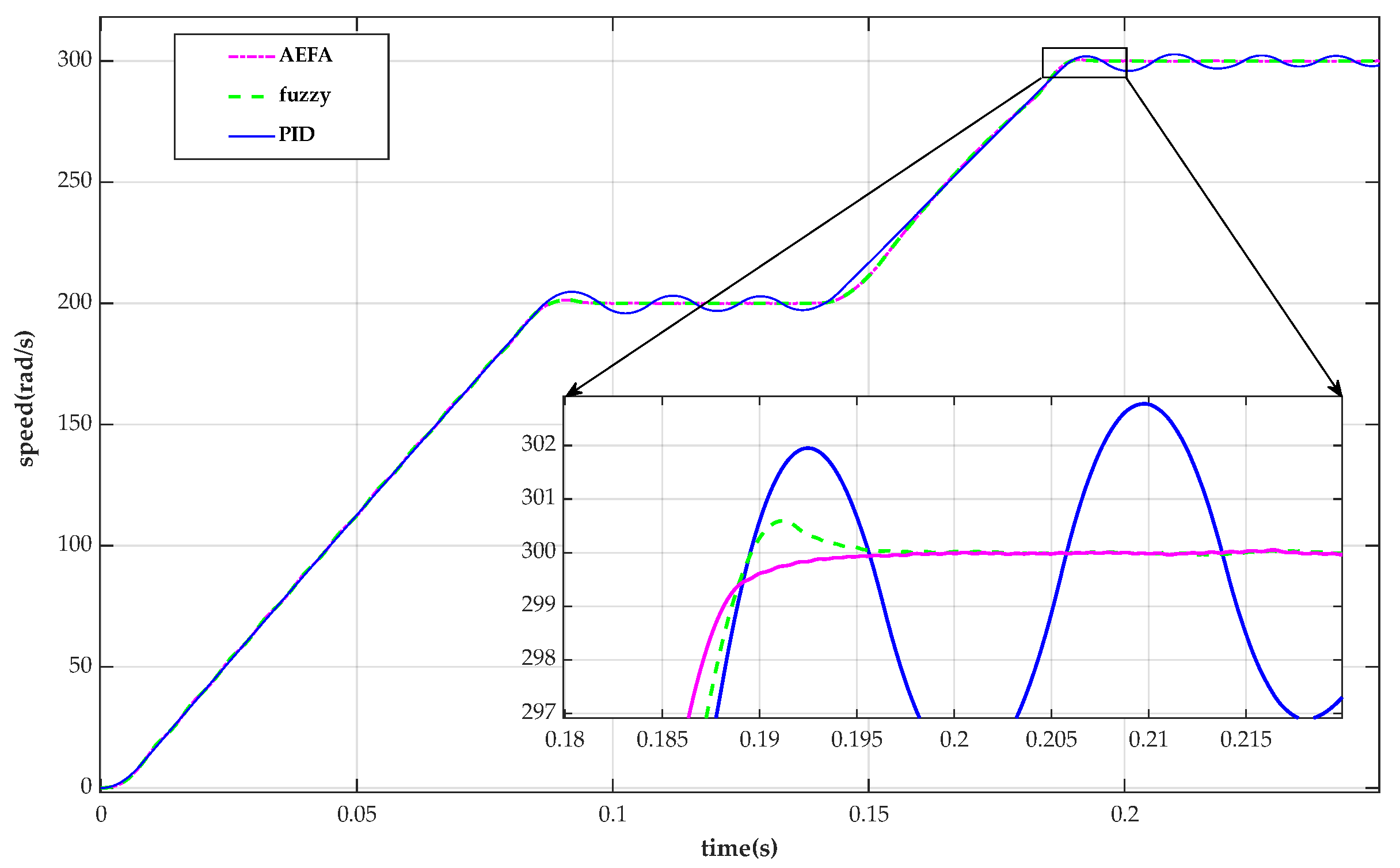
The speed response of the BLDC motor for all controllers under a variable setting speed condition is given in
Figure 13. In order to test the speed fluctuation of the controller when the speed is switched, a change to the set speed condition is introduced. The reference speed is changed from 200 rad/s to 300 rad/s at 0.14 s. It is apparent that the overshoot of the fuzzy PID–AEFA controller is minimal when the new steady state is reached. This shows that the fuzzy PID–AEFA controller keeps the speed of the BLDC motor system more stable when the speed is changed.
The peak values of the three controllers are listed in
Table 4. The peak value under the full load condition is the lowest value of waveform decline after interference. Through the above simulation results, we can conclude that the fuzzy PID–AEFA control method proposed in this paper significantly improves the speed fluctuation of the BLDC motor, reduces the overshoot, and improves the dynamic characteristics. The control performance has been improved compared with the traditional PID control and fuzzy PID control.
In summary, by simulating the BLDC motor control system, it is proved that the fuzzy PID controller based on AEFA optimization is superior to the traditional PID controller and the fuzzy PID controller.
5. Conclusions
In order to improve the accuracy of the attitude control flywheel of a small satellite, it is necessary to improve the stationarity of the BLDC motor in the flywheel. To reduce the speed pulsation of the BLDC motor and improve the stability of the BLDC motor, this paper combines fuzzy control technology with PID control and proposes a new method based on AEFA to optimize the parameters of the fuzzy PID controller. By establishing the simulation model of the BLDC motor for testing, it is found that the algorithm has good optimization performance and improves the control accuracy of the BLDC motor control system when there is a big difference between the discourse domain of fuzzy logic and the input of the fuzzy controller.
In order to test the effectiveness of the controller proposed in this paper in the actual operating environment, various operating conditions such as no-load, full-load, and variable set speed were considered, and its performance was observed. The simulation results showed that the fuzzy PID–AEFA controller proposed in this paper is significantly better than the traditional PID control and fuzzy PID control in performance indicators, and can effectively reduce the overshoot, adjustment time, stabilization time, and steady-state error of the BLDC motor. It is proved that the use of the fuzzy PID–AEFA controller can more effectively compensate for disturbances and reduce the speed fluctuations caused by load changes and external disturbances, which verifies the effectiveness of the algorithm.


