Article

Hybrid Electric Powered Multi-Lobed Airship for Sustainable Aviation

1
Department of Aeronautical and Automobile Engineering, Manipal Institute of Technology, Manipal Academy of Higher Education, Manipal 576104, Karnataka, India
2
Department of Engineering Management, College of Engineering, Prince Sultan University, Riyadh 11586, Saudi Arabia
3
Department of Mechanical Design and Production Engineering, Faculty of Engineering, Zagazig University, Zagazig 44519, Sharkia, Egypt
4
Department of Aerospace Engineering, Faculty of Engineering, Universiti Putra Malaysia, Serdang 43400, Selangor, Malaysia
*
Authors to whom correspondence should be addressed.
Aerospace 2022, 9(12), 769; https://doi.org/10.3390/aerospace9120769
Submission received: 3 November 2022 / Revised: 19 November 2022 / Accepted: 24 November 2022 / Published: 29 November 2022

Abstract

:
The excessive depletion of fossil fuels and increasing environmental concerns have led to the need to explore alternative sources of power for aircraft. This has spurred various stakeholders in the aerospace industry to explore hybrid electric propulsion technology and fully electric vehicles. Airships are aerial platforms based on lighter-than-air systems technology. They have several unique features compared to other vehicles, chiefly their being more environmentally friendly due to low fuel consumption. Among airships, lifting-body dynastats are the most suitable configuration for implementing different levels of hybridization in propulsion systems owing to their large surface-to-volume ratio. The present study deals with the relevance of a hybrid propulsion (conventional engine + electric motor) system and its comparison to conventional ones. An objective function based on envelope volume is formulated to achieve an optimal configuration of a tri-lobed dynastat to carry 10 tons of payload over a 500 km range for specified operating conditions powered by conventional fuel and batteries. The design space is explored assuming a predicted future battery technology level with specific energies ranging from 250 to 750 Wh/kg. Three case studies based on the source of power are investigated: fuel alone, fuel + batteries, and fuel + batteries + solar array. It is seen that the airship can be fully electric with zero carbon emissions but at the expense of a longer length (+18%) and higher envelope volume (+63%) compared to the baseline model.

1. Introduction and Background

Green aviation is one of the hottest topics in today’s aeronautics research. Depleting fossil fuels and greenhouse gas (GHG) emissions are the two major concerns of air transportation. Every year, the increase in air traffic across the globe raises concerns about environmental pollution and global warming due to GHGs. Based on the current growing demand, it is estimated that passenger traffic will increase by 6% globally with 48% within the Asian region by the year 2035 [1]. The aviation sector substantially impacts global economic, social, and cultural development. It is a significant contributor to GHG emissions and is responsible for 2% of total fuel consumption by the transportation industry. Aviation’s contribution to the global emission of GHGs is estimated to be 13% of the total of different modes of transportation [2]. The drastic rise in air travel will result in enormous GHG emissions without a substantial reduction of fossil fuel burn. There is also a huge demand for civil transportation that is greener and more flexible than existing modes of transportation. As depicted in Figure 1 (based on a survey by the UK-based company HAV), airships and railways are relatively clean options compared to automobiles and airplanes. Compared to rail transportation, the ground infrastructure required for hybrid airship operation is minimal.
Though GHG emissions and their impact on the environment and livelihood are the primary concerns in looking for a potential solution for propulsion technology, there are also other important aspects to be considered. Due to the cold war between the countries that are the major suppliers of crude oil, there is a massive gap in its supply, and the cost is skyrocketing. The development of hybrid propulsion technology for aviation application will significantly reduce the dependence on conventional fuels and becomes cheaper in terms of operating cost on a global scale. Another significant concern about the conventional propulsion system is its noise generation. With hybrid propulsion technology, this can be eliminated or at least considerably reduced [3,4].
Many ideas can be found in the open literature to reduce the dependency of the aviation sector on conventional fuels. Most studies [5] have focused on using solar energy extracted through photovoltaic arrays as a renewable energy source to power aircraft. This technique was successfully demonstrated on unmanned aerial vehicles (UAVs) such as Sunriser [6], Helios [7], Skysailor [8], Heliplat [9], So Long [10], Xihe [11], and Solar Impulse HB-SIA [12]. However, this is not so efficient for large commercial aircraft due to the limited planform area to install the array. Another interesting idea to replace conventional fuel is using bio-fuels for commercial aircraft [13,14]. The next most popular technology is the application of energy storage devices such as rechargeable batteries [15], hydrogen, and fuel cells [16] as an alternate source of power for aircraft with the hybrid propulsion system. Regenerative fuel cell technology is another most-promising technology with an energy density on the order of 400 to 1000 Wh/kg [17]. Though the energy density is higher than that of rechargeable batteries, the weight penalty due to the associated components of the fuel cell is one of the major drawbacks, and it causes complexity in the installation and the aircraft’s flight dynamics [18].
All over the globe, there are several research projects in progress to improve current systems and methodologies. Electric propulsion technology is a potential solution to reduce fossil fuel consumption and GHG emissions. Automotive industries such as Tesla (USA), Rivian (USA), Nio (China), and Xpeng Motors (China) have successfully demonstrated the application of pure electric and hybrid propulsion technology. For aviation, however, this technology is still in the nascent stage. Many drawbacks are involved in applying fully electric propulsion technology for larger aircraft: a significant one being immature battery technology. With current battery technology, potential solutions are being developed for smaller aircraft such as unmanned aerial vehicles (UAVs) and general aviation aircraft (GAs).
The specific energy of energy storage devices such as batteries is much lower than that of fossil fuels. Lithium-ion batteries are widely used in automotive and aerospace applications, especially for remotely piloted aircraft systems (RPASs), due to their high theoretical energy density and long life [19,20,21]. Currently, the maximum specific energy obtained from Li-ion batteries ranges from 0.15 to 0.25 kWh/kg [22]. The specific energy of aviation gasoline and Jet A-1 are 12.22 kWh/kg and 11.99 kWh/kg, respectively. The available battery technology possesses a maximum specific energy two orders of magnitude lower than that of jet fuel [22,23]. Various factors affect a battery’s specific energy, such as chemical composition, state of charge, charging and discharging rate, and the number of charging cycles [24].
Several challenges are involved in designing an aircraft with hybrid propulsion technology. Firstly, there is a weight penalty due to the fact that hybrid propulsion tends to be much heavier than conventional propulsion. The low specific energy factor of the battery affects the aircraft’s size and payload capability.
Many existing studies [25,26,27,28] have proposed the concept of hybrid electric propulsion technology for existing civil aircraft such as ATR-72, A320, etc. A number of articles focus on the conceptual sizing and performance analysis based on hybrid electric propulsion technology for commercial aircraft [29,30,31,32], general aircraft [33,34,35,36], and UAVs [3,37,38]. Publicly available literature on conceptual design based on hybrid electric propulsion for airships is scarce. Though an airship is the most suitable platform to implement hybrid technology for propulsion, very few studies have focused on this subject. The present study addresses the significance of hybrid propulsion technology and the capability of the hybrid airship as a potential solution for greener aviation.
The infeasibility of commercial airplane hybridization is due to the substantial weight and volumetric penalty of the energy storage systems necessary to supply a large amount of power [39]. The overall efficiency of battery-powered aircraft is estimated to be 73%; this is estimated by combining the efficiency of each component of the system, including the battery (100%), controller (98%), electric motor (95%), gearbox (98%), and propeller (80%) [40]. However, there are many advantages to using conventional fuel for civil aircraft. Fuel is stored in the wings of aircraft for safety considerations, so it does not affect the payload volume. Fuel has a high volumetric energy density compared to all the alternative energy sources. The technological development of batteries, electric propulsion units, and accessories must be accelerated to be advanced enough for aeronautical applications. Based on current technological advancement, it is estimated that batteries with an energy density of 750 Wh/kg will not be available before the year 2035 [41]. Though aircraft have various advantages compared to airships, there is still a long way to achieve a 100% degree of hybridization.
In recent years, airships, also known as lighter-than-air systems (LTA), have been considered to be a suitable platform for various applications such as heavy cargo transportation [42,43,44], high altitude long endurance (HALE) flight [45,46,47], surveillance and monitoring [48,49,50], and telecommunications [51]. Airships are categorized based on their internal structure and source of lift. Airships that can generate 20–40% aerodynamic lift are called hybrid airships [52,53]. Among hybrid airships, multi-lobed dynastats have various advantages for civil and defense applications [54,55,56,57]. Multi-lobed dynastats have a large surface-to-volume ratio compared to conventional ones (airships with an axis-symmetric body-of-revolution), as shown in Figure 2, which is a great advantage for the installation of photovoltaic (PV) cells over their surface [58]. In the present study, a lifting-body dynastat with a tri-lobed envelope is considered for applying a hybrid propulsion system.
PV arrays generate power from solar energy, and their efficiency depends on curvature, ambient temperature, day of operation, flight ceiling, and operating location [59]. Flat-paneled solar arrays are more efficient compared to the curved panels [60]. A multi-lobed airship configuration has a relatively flatter upper surface that enhances the efficiency of PV arrays. Among PV cells, silicon cells are widely used for solar-powered aircraft and have efficiency ranges between 16–22% [5]. Skysailor, Xihe, and Sunrise II are the three solar-powered UAVs that have utilized mono-crystalline silicon PV cells, having a conversion efficiency of 16%. In the existing literature, the conversion efficiency of the PV cells was taken between the range of 12–16%.
For an airship, the majority of the energy is required to overcome drag, and the maximum lift comes from the buoyant gas. In general, airships fly at a Mach number of less than 0.2. These are the advantages for the airship to implement hybrid propulsion technology with a greater degree of hybridization.
In hybrid-electric-powered vehicles, the propulsive energy required to overcome the drag is supplied by two or more energy sources: fuel, a rechargeable battery or fuel cell, and a solar array. There are three main architectures of the hybrid propulsion systems, as shown in Figure 3: series, parallel, and series–parallel [61,62,63].
In the series configuration, the internal combustion engine (ICE) is connected to the generator to produce only electricity. The electrical motor is the primary source of power. The advantage of a series configuration is the minimal space occupied by the system compared to other architectures, and a wide variety of ICEs can be used. The main drawback with this configuration is that the whole system fails when the electrical motor fails. Series hybrid architecture is widely used in road vehicle applications [64]. However, the weight of the series architecture is higher than that of the parallel one, which is an important parameter to be considered for aerospace applications [65]. In the parallel model, unlike the series architecture, the mechanical bus can be driven by either an ICE or an electric motor. This architecture is mechanically complex and less fuel efficient due to variations in the operating speed of drive [66]. Based on the weight factor, a parallel configuration is selected as a potential solution for hybrid electric powered aircraft [25].
Hybrid electric propulsion technology can be implemented with different degrees of hybridization. The hybridization factor is a key parameter that defines the energy ratio from batteries to the total energy. The term Ψ (degree of hybridization, DoH) is equal to zero for fuel-powered aircraft and one for fully electric aircraft.
Ψ = E b a t t E b a t t + E f u e l
Ψ = 0 Conventional 1 Fully - electric
It is impractical to achieve a hybridization factor equal to one for commercial aircraft with the currently available batteries. For an aircraft, batteries with a specific energy of 500 Wh/kg is a minimum requirement [67]. Moreover, commercial aircraft do not have sufficient planform area for installing PV arrays as an alternate power source in combination with rechargeable batteries. A multi-lobed dynastat can be a potential solution in the future for passenger and cargo transportation over a shorter range. The advantage of a flatter upper surface and the larger surface-to-volume ratio of a dynastat supports the hybrid electric propulsion technology to a larger extent. Hybridization can be improved with the help of the installation of PV arrays over its surface to generate power from the solar energy during daytime to partially support the power required by the onboard systems of an airship and to recharge the batteries. This, in turn, reduces the dependency on power from the energy storage batteries. Moreover, the areal density of the PV arrays is not so high as to add a weight penalty to the airship.
The main objective of the present study is to demonstrate the potential benefits of the multi-lobed hybrid airship as an ideal platform for greener aviation with zero carbon emissions. The design problem was formulated in such a way as to involve multiple disciplines with fewer assumptions to match reality. An attempt was made to utilize the benefit of the large planform area of an airship for solar array installation to reduce the dependency on batteries, and we also investigated the effect of hybridization in a combination of batteries with solar arrays.

2. Design Methodology

Airship sizing is a multi-disciplinary design process and involves various disciplines such as geometry, environment, structures, thermal, aerodynamics, stability and control, materials, etc. Figure 4 shows the disciplines involved in the sizing process and layout of the scheme followed for the optimization task in the present study. The geometry module includes a shape generation algorithm to define the shape of each lobe of the envelope and the elemental approach for solar array generation over the surface of the envelope. The aerodynamic module calculates the aerodynamic drag of the tri-lobed envelope and the aerodynamic lift at a given angle of attack. In this study, the angle of attack of the airship was fixed to be 3°. From an existing study [68] and the present study, it was observed that the change in drag coefficient is minimal between the range of angles of attack from zero to 3°. The volumetric drag coefficient of the hull was estimated by the semi-empirical relation shown in Equation (6), which is explained in detail in Section 2.2 and was proposed by Hoerner for an axisymmetric body of revolution at a zero-degree angle of incidence assuming the tri-lobed envelope as an equivalent ellipsoid.
The tri-lobed dynastat was considered a reference model for the present study. Tri-lobed envelope geometry is a combination of three lobes placed parallel to each other and at an offset (f) laterally, as shown in Figure 5. To maintain the large surface-to-volume ratio, the lateral distance between the lobes was fixed to be 0.3 times the diameter of a lobe. The longitudinal and vertical distance between the center of the lobes was assumed to be zero. The length of the airship was allowed to vary to achieve the optimum envelope volume for the given operating conditions and constraints. The profile of each lobe was fixed to be an ellipsoid. The profile of the lobe was generated using Gertler’s shape generation algorithm [69,70]. This algorithm allows the user to achieve the profile of any standard shapes, e.g., ellipsoid [71], NPL [72], GNVR [73], Zhiyuan-1 [74], and Wang [75], or a non-standard shape of the airship with the axisymmetric body of revolution.
The shape generation equation, Equation (3), depends on five design variables: location of maximum diameter (m), nose radius ( r 0 ), tail radius ( r 1 ), prismatic coefficient ( C p ), and length-to-diameter ratio ( l / d ).
y ( x ) = d a 1 x l + a 2 x l 2 + a 3 x l 3 + a 4 x l 4 + a 5 x l 5 + a 6 x l 6
where a 1 , a 2 , , a 6 are the shape coefficients that can be obtained from solving the six non-linear equations shown in Equation (4) simultaneously.
1 1 1 1 1 1 1 0 0 0 0 0 1 2 3 4 5 6 m m 2 m 3 m 4 m 5 m 6 1 2 m 3 m 2 4 m 3 5 m 4 6 m 5 1 2 1 3 1 4 1 5 1 6 1 7 a 1 a 2 a 3 a 4 a 5 a 6 = 0 2 r 0 2 r 1 1 / 4 0 ( 1 / 4 ) C p
To obtain the final envelope surface, the curve generated from Equation (3) is revolved around the desired axis to produce the axisymmetric shape of the airship. In the present study, the ellipsoid shape was selected as the envelope profile. In terms of the Gertler-58 shape generator, the values of the five design variables required to estimate the ellipsoid profile are given in Table 1.
For the solar-powered configuration, the PV array was generated over the surface of the envelope by fixing both the starting point and the ending point of the array with respect to the length of the airship and the intended angle of the array. It is a fact that power generation by solar array depends on the day of operation, geographic location, operating altitude, and orientation of the airship. In the present study, the day of operation was chosen as summer solstice ( I d a y = 172), and the orientation of the airship with respect to the Sun reference frame was fixed to be 90°.

2.1. Problem Formulation

A single-point optimization problem was formulated to achieve the tri-lobed airship of minimum envelope volume that satisfied the given constraints. The problem was solved using the Particle Swarm Optimization (PSO) solver in the Global Optimization Toolbox in MATLAB®. The constraints were based on weight–lift balance and energy balance as shown in Equation (5).
minimize : V e n v e l o p e s . t . W L t o t a l 0   weight - lift   balance P r e q P s u p 0   power   balance
where L t o t a l is the total lift of the airship and includes buoyant lift ( B = Δ ρ V e n v g ) and aerodynamic lift, E r e q is the energy required by the airship to overcome the drag at cruise altitude and can be calculated as E r e q = P r e q × Time (in h)⇒ P r e q = 0.5 ρ V 3 V e n v 2 / 3 C d , t o t a l .
The operating altitude (h = 4.88 km) and engine specifications of Airlander 10 were used for this study. Airlander 10, originally developed as the HAV-304, is a double-hulled lifting-body dynastat designed and built by British manufacturer Hybrid Air Vehicles (HAV). It is powered by four Thielert Centurion 4-liter V8 turbocharged diesel engines with a shaft power of 242 kW. The weight of the engine was taken as 283.5 kg. The cruise velocity of Airlander 10 of 148 kph was considered for the present study. A lithium-ion battery with a specific energy of 250 Wh/kg was chosen as the source of power for the base model. For the electric motor, a Siemens–FlyEco Magnus eFusion was selected; it weighs 50 kg and provides 260 kW shaft power [76].

2.2. Drag Estimation

Drag is an important parameter during the sizing and performance analysis of the multi-lobed airship. The Bréguet range equation shows that the range is a function of drag and is inversely proportional to it. Estimating the drag of a multi-lobed airship is not an easy task. There is a simplistic approach to calculating the volumetric drag coefficient of a bare hull in which an unconventional airship can be treated as an equivalent ellipsoid model. Some studies [48,53,77] have assumed the unconventional airship equivalent to a conventional airship as an equivalent ellipsoid and estimated the drag coefficient of the envelope using a semi-empirical relation proposed by Hoerner [78]. Hoerner’s equation, shown in Equation (6), calculates the zero-lift volumetric drag coefficient based on the length over diameter ( l / d ) ratio and Reynolds number (Re).
C D V = C f 4 l d 1 / 3 + 6 d l 7 / 6 + 24 d l 8 / 3
The friction coefficient ( C f ) represented in Equation (7), which is only dependent on the Reynolds number, can be estimated as
C f = 0.045 R e 1 / 6
CFD is one of the frequently used tools in the study of the aerodynamics of an LTA system. A myriad of open literature is available on the numerical computation of aerodynamic forces for conventional airships with an axisymmetric body of revolution. There are few works of literature [68,79,80,81,82] available on hybrid airships with unconventional shapes and multiple lobes. These articles do not provide enough details on the geometry of the model used for the CFD analysis. There is also a dearth of sufficient aerodynamic data on hybrid airships available to the public.
The most challenging task in using CFD for the computation of aerodynamic forces of a hybrid airship is validating the results. Since there are no publicly available wind tunnel data for multi-lobed hybrid airships, aerodynamic assertions drawn from a CFD study can be done merely based on the solver’s ability to capture the flow physics associated with airship flow through the analysis of flow-field visualization and pressure–velocity flow-field data. Due to the lack of sufficient aerodynamic data on hybrid airships, few studies have assumed their drag characteristics relative to that of their conventional airship version. Brandon [48] presented a comparative study between a conventional airship and a lifting-body hybrid airship in which the zero-lift drag coefficient was assumed to be 1.5 times the value of that of a conventional ellipsoidal airship. According to the study, the ratio of the zero-lift drag coefficient of a conventional airship to that of a double-hulled lifting body airship ranges between 1.4 and 1.65. Carrión et al. [68] demonstrated the efficiency of a CFD solver to investigate the aerodynamic characteristics of a multi-lobed hybrid airship with a shape similar to that of the Airlander 50 airship of Hybrid Air Vehicles (HAV) Ltd. Authors have also used the equivalent ellipsoid method to estimate the volumetric zero-lift drag coefficient of a multi-lobed bare hull. The drag coefficient of a multi-lobed hull using CFD was estimated to be nearly 40% more than that of the equivalent ellipsoid model as shown in Figure 6a. Based on pre-existing studies, we [77] presented a comprehensive comparative study of conventional and tri-lobed lifting body hybrid airship and proposed the zero-lift drag coefficient of the bare hull to be 1.5 times the value of that of a conventional single-lobe airship. The lack of sufficient CFD investigations related to hybrid airships can be attributed to the fact that hitherto studies have not provided enough details on the geometry of the airship model being used for CFD analysis. Consequently, studies related to aerodynamic comparisons between conventional and tri-lobed airships are even more scarce. In one study, we compared the aerodynamic characteristics of a conventional airship to that of a tri-lobed model with the same envelope volume. The shape of the conventional airship and each lobe of the tri-lobed model was considered LOTTE. The reason for choosing the LOTTE model was the availability of experimental data to validate the CFD results. The difference in the volumetric drag coefficient between the conventional bare hull and the tri-lobed configuration without fins was estimated to be 45–48% from zero to four degrees angle of attack, as shown in Figure 6b. Therefore in the present study, the volumetric drag coefficient of the tri-lobed model was calculated from an equivalent ellipsoid model using Hoerner’s equation multiplied by a factor of 1.5 to account for the error between the semi-empirical formula and CFD data.

2.3. Mass Estimation

For the present study, the mass-breakdown module was developed from the existing literature [52,56,83]. The total mass of a fuel-powered airship is estimated using Equation (8):
M t o t a l = M h u l l + M t a i l + M p r o p + M f u e l + M m i s c
For the electric-powered airship, the total mass can be expressed as Equation (9):
M t o t a l = M h u l l + M t a i l + M p r o p + M a r r a y + M e s + M m i s c
where M h u l l is the mass of the hull, M t a i l is the mass of the horizontal and vertical tail, M p r o p is the mass of the propulsion unit, M f u e l is the mass of fuel (reserve fuel not included), M a r r a y is the mass of the solar array, and M e s is the mass of the energy storage devices. Mass of miscellaneous M m i s c components includes the electronic systems, internal supporting structures, landing system, engine mounting, etc.
The hull, septum, and tail mass were estimated based on the areal density ( ρ f a b r i c ) of the fabric material used. We assumed the hull and tail materials have the same areal density and are made from a Vectran laminate. The areal density of the Vectran laminate is 0.105 kg/m2. The mass of the hull expressed in Equation (10) includes the factors for manufacturing ( F m = 1.2 ) and attachment fittings ( F a f = 1.26 ) [52].
m h u l l = F m F a f ρ f a b r i c S A e n v
Similarly, the mass of solar arrays and energy storage devices can be estimated from Equations (11) and (12):
m a r r a y = ρ a r r a y S A a r r a y
m e s = P r e q × T / E s p e c
where P r e q is the total power required by the airship to overcome the drag and to operate the onboard systems, T is the duration of daytime on a particular day, and E s p e c is the specific energy of the energy storage devices.
The mass of other key components such as fins, propulsion system, energy-storage devices, supporting structures, electrical systems, and avionics were calculated using the formulae given by Carichner and Nicolai [52].

3. Results and Discussions

To investigate the effect of the hybrid propulsion system on the performance of the multi-lobed dynastat, a baseline model was designed using a conventional propulsion system powered by fossil fuel. The specific energy of the fuel was considered as 11.89 kWh/kg. The optimal outcome of the baseline model is given in Table 2. In order to understand the impact of the application of hybrid propulsion technology on the sizing and performance of the airships, the baseline model was employed with the hybrid propulsion system powered by fossil fuel, and the battery was implemented at various degrees of hybridization.

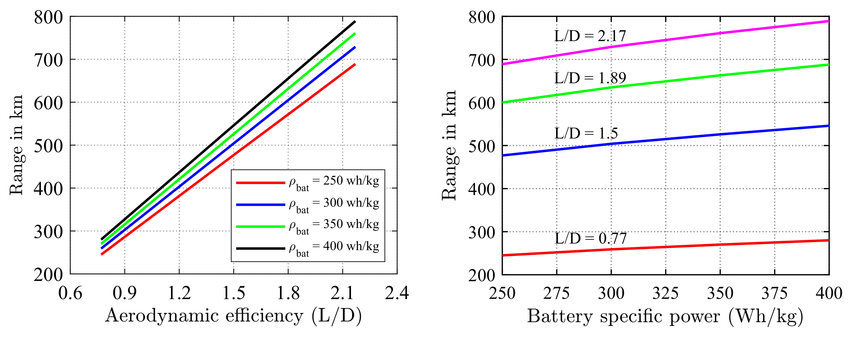
3.1. Effect of Hybridization on Range

To study the impact of hybrid propulsion technology on the performance of an aircraft, the Bréguet range equation is the widely used expression. In a general form, the Bréguet range equation (see, e.g., [84,85,86,87]) appropriate for power-rated aircraft, such as those using piston–prop and turboprop engines flying at a constant angle of attack and airspeed, can be expressed as Equation (13):
R = η p c p L D ln W O E + W P L + W f u e l W O E + W P L
where W O E + W P L + W f u e l equals the initial weight of the aircraft, and W O E + W P L represents the final weight.
The Bréguet range equation for an airship can be expressed as Equation (14) [88]:
R = η p c p C L C D ln W A i W A f
where W A i = W O E + W P L + W f u e l B , and W A f = W O E + W P L B .
From the range equation, the fuel weight W f u e l for a conventional dynastat can be written as Equation (15):
W f u e l = W A f e x p R η p c p C L C D W O E + W P L B
The initial sizing of the tri-lobed hybrid airship was achieved from a single-objective optimization problem solved by utilizing the PSO technique. This involves iterating the multiple levels of equations and fixing different design variables, such as the airship’s empty weight, battery weight, fuel weight, specific energy, etc. A target range of 500 km was chosen because most electric and hybrid vehicles can travel a similar distance with fewer battery recharges or refueling, as shown in Figure 7.
From the comparative study, the airship is superior in performance and gives a range of 300–750 km for the different lift-to-drag ratios. To verify the obtained results, the modified Breguet’s range equation (Equation (17) from reference [89]) was used to incorporate the concept of the hybridization factor into the design. The Breguet range equation does not apply to electric aircraft because their weight does not change as energy is used. Therefore, a power-balance approach is used, which is derived from the original equation and modified as shown in Equation (16) for the constant weight.
R e l e c t r i c = c b g C L C D W b a t t W T O η i η m η p
where C L / C D is the lift-to-drag ratio (viz., aerodynamic efficiency), c b is the battery-specific energy (energy/mass), W b a t t and W T O are the battery weight and takeoff weight, respectively, and η i , η m , and η p are the efficiencies of the inverter, motor, and propulsion system, respectively.
Equation (16) is parameterized in a different form shown in Equation (17) so that it reflects the real aircraft design process more closely and helps to investigate the impact of hybridization on the maximum take-off weight (MTOW) of the airplane/airship. MTOW is a key indicator of design complexity and also operating and maintenance costs.
R t o t = C L η i η m η p g C D η g c p ln [ A ] + B
where
A = ( Ψ + ( 1 Ψ ) c b c p ) W T O m a x Ψ W T O m a x + ( 1 Ψ ) c b c p ( W p a y + f w e W T O m a x )
and
B = Ψ c b ( 1 f w e ) W T O m a x W p a y Ψ W T O m a x + ( 1 Ψ ) c b c p ( W p a y + f w e W T O m a x )
The term Ψ represents the percentage of total mission energy provided by the batteries (DoH); f w e represents the empty weight fraction defined as the ratio of empty weight ( W e ) to the maximum takeoff weight (MTOW).
The comparison study shows that the same specific fuel and battery ratings with an increase in lift-to-drag ratio can help us to increase the range, as shown in Figure 8. From the range equation, the range and aerodynamic efficiency are directly proportional. For the different degrees of hybridization, a reduction in aerodynamic efficiency and an increase in airship mass affect the range performance.

3.2. Case Study 1: Conventional Multi-Lobed Airship

The multi-lobed airship configuration shown in Figure 9a is a variant powered by the hybrid propulsion technology using a fossil fuel along with the batteries, and Figure 9b represents the airship model powered by fuel and batteries in combination with the solar array. Figure 10a,b present the drag and mass distribution, respectively, of the baseline model powered by the conventional propulsion system. The hull of the airship is the major contributor to drag. With the help of aerodynamic-based shape optimization, the drag due to the complex shape of the envelope can be reduced, which in turn improves the degree of hybridization of the hybrid propulsion system.

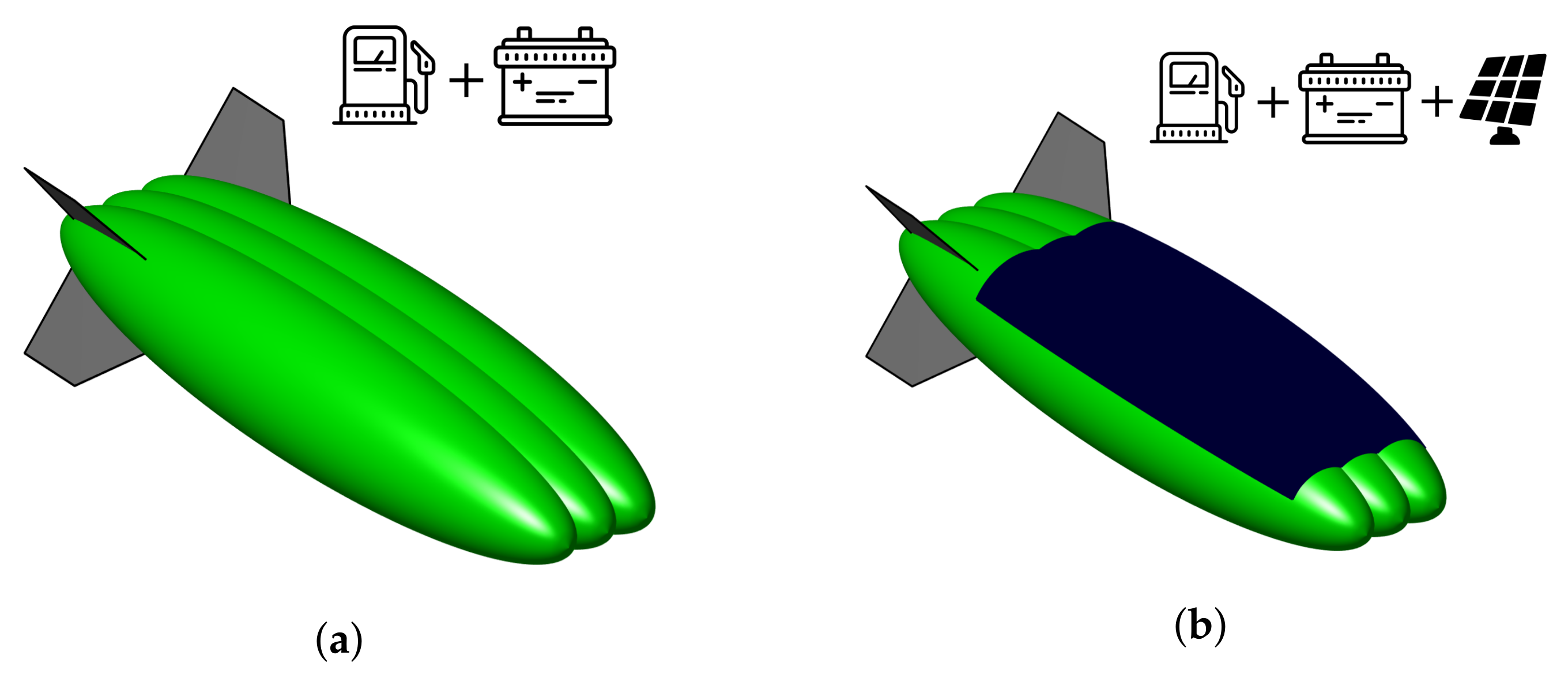
3.3. Case Study 2: Hybrid-Electric-Powered Multi-Lobed Airship

The effects of the energy split and the specific energy of the batteries on the fuel mass, battery mass, and payload mass are investigated on the baseline model. A trade-off between payload weight, fuel weight, and battery weight at various degrees of hybridization is shown in Figure 11. The trade-off study reveals multi-lobed airships’ payload capability and feasibility for hybrid propulsion technology. In this study, the parallel architecture of the hybrid propulsion system was chosen due to its advantages over the series architecture. The efficiency of the electric system ( η e l e c = η b a t t e r y η i n v e r t e r η w i r i n g ) of the chosen architecture was estimated to be 0.86 and consists of the battery ( η b a t t e r y = 0.95 ), inverter ( η i n v e r t e r = 0.95 ), and wiring ( η w i r i n g = 0.95 ). The efficiency of the electric motor ( η m o t o r ), mechanical bus ( η M B ), and propeller ( η p r o p ) were taken as 0.98, 0.95, and 0.80, respectively.
In all three case studies, the design range was fixed to be 500 km. The maximum degree of hybridization achievable with the baseline model for different specific energies of the battery is visualized in Figure 11. The battery mass increases significantly with an increase in the degree of hybridization, and fuel mass decreases. For a battery with a specific energy of 250 Wh/kg, a maximum of a 67% degree of hybridization can be achieved by a trade-off of 51% of the payload. The trend lines in Figure 11 show that a fully electric airship can be achieved by improving battery technology and battery specific energy. With battery technology with a specific energy of 370 Wh/kg, an airship can be converted to fully electric by a trade-off of nearly 51% of the payload. With further advancement in battery technology, the trade-off with the payload can be reduced significantly.

3.4. Case Study 3: Hybrid-Electric-Powered Multi-Lobed Airship with Solar Array

To get better insight and to investigate the effect of adding solar arrays for the addition of energy through a renewable source, we selected one specific hybrid electric design to evaluate in more detail. The benefits of a hybrid electric propulsion system powered by solar energy in addition to battery and fuel are explored for various efficiencies of photovoltaic cells. This is done assuming the availability of batteries with a specific energy of 750 Wh/kg and a thin-film photovoltaic array (amorphous silicon) with an efficiency of 12%.
Without compromising the payload capability of the airship, the fully electric tri-lobed model was designed and optimized for the minimum envelope volume shown in Figure 12. A comparison between the design with selected battery-specific power (viz., ρ b a t = 750 Wh/kg), the photovoltaic array’s efficiency, and the reference design are presented in Table 3.
The data of the modified model are presented in Table 3 and correspond to the baseline model in which the conventional propulsion system was replaced by a hybrid propulsion system powered by batteries with a specific energy of 750 Wh/kg and a solar array with a conversion efficiency of 12%. The optimized data correspond to the tri-lobed configuration obtained for hybrid propulsion technology of the same payload capacity powered by batteries with a specific energy of 750 Wh/kg and a solar array with a conversion efficiency of 12%.
Figure 13 shows the general trends and gives an overview of the whole design space. These are the outcomes of the specific hybrid electric design we selected to evaluate in more detail. Higher benefits are obtained for designs with better battery technology. The airship can be fully electric with zero carbon emissions at the expense of a larger airship in terms of length (+18%) and volume (+63%). The payload capacity of the airship was fixed at 10,000 kg. From the results, it can be concluded that there is a chance to reduce carbon emissions drastically in the future with the help of hybrid airships for heavy cargo transportation and for carrying passengers on short-range missions. This will be possible through sufficient technological progress, particularly pertaining to battery technology with high specific energy density. There are many advantages to selecting a multi-lobed airship configuration for the application of hybrid propulsion technology.

4. Conclusions

The present study highlights the potential benefits of a tri-lobed dynastat with hybrid propulsion technology for greener aviation. Multi-disciplinary design optimization (MDO) was performed, incorporating some of the key disciplines of a multi-lobed hybrid airship: geometry, aerodynamics, environment, energy, and structures. However, optimization based on these disciplines by themselves does not provide a complete picture of the difficulties faced by designers in the later stages of the design process. To reduce computational complexity, a low-fidelity aerodynamics model based on an equivalent ellipsoid method with a correction factor to account for uncertainty in the solution was used to estimate the volumetric drag coefficient of tri-lobed envelopes. A component build-up method that involves semi-empirical formulae was used to estimate the mass of each component of the airship without many assumptions. It is seen that the hybridization of airships relies on significant improvements in battery technology and the conversion efficiency of photovoltaic cells. The results indicate that a tri-lobed airship is a potential solution for greener aviation and can be fully electric with zero carbon emission.
  • Aerodynamic efficiency and battery-specific power have a significant impact on the performance of an airship designed for low-altitude cargo transportation.
  • Conventional hybrid airships can be turned into fully electric at the expense of payload weight reduction by ∼50%. The payload weight capability can be significantly improved with better battery technology in the future. Fuel cell technology can be another potential solution for electric-powered airships.
  • To understand the conflicts between the degree of hybridization and sizing of the multi-lobed airship, a single-objective optimization problem may not be sufficient to derive solid conclusions.
  • Multi-objective multi-disciplinary design optimization problem must be formulated to obtain design numbers that provide more insight into the complexities involved in achieving fully electric hybrid airships.
  • The proposed methodology is very flexible in incorporating the multiple disciplines at various stages of the design process and efficient in terms of computational time to derive a better understanding of the impact of hybrid propulsion technology on the initial sizing of hybrid airships.
  • There is a scope for further improvement to the design process incorporating hybrid propulsion technology for future electric hybrid airships that has been laid out in this study.

Author Contributions

Conceptualization—M.M., D.F.T. and B.S.; methodology—M.M. and D.F.T.; software—M.M. and B.S.; validation—M.M. and B.S.; writing—original draft preparation—M.M.; writing—review and editing—M.M., B.S. and T.K.; supervision—T.K. and T.A.S. All authors have read and agreed to the published version of the manuscript.

Funding

This research received no external funding.

Institutional Review Board Statement

Not applicable.

Informed Consent Statement

Not applicable.

Data Availability Statement

Some or all data, models, or codes that support the findings of this study are available from the corresponding authors upon reasonable request.

Acknowledgments

We authors would like to thank Katkuri Aditya Vardhan Reddy and Harsh B. Patil, undergraduate students in the Department of Aeronautical and Automobile Engineering, Manipal Institute of Technology, Manipal, India, for extending their support in performing the calculations and to prepare the manuscript in its present form.The authors would like to acknowledge the support of Prince Sultan University, Riyadh for paying the article processing charge (APC) for this publication.

Conflicts of Interest

The authors declare no conflict of interest.

References

  1. Madhwal, Y.; Avdeeva, Z. Planning in Aircraft Industry based on prediction of Air Traffic. Procedia Comput. Sci. 2017, 122, 1047–1054. [Google Scholar] [CrossRef]
  2. ICAO. Environmental Report 2010-Aviation and Climate Change; ICAO: Monteal, QC, Canada, 2010. [Google Scholar]
  3. Friedrich, C.; Robertson, P. Hybrid-electric propulsion for automotive and aviation applications. Ceas Aeronaut. J. 2015, 6, 279–290. [Google Scholar] [CrossRef] [Green Version]
  4. Lee, J.J.; Lukachko, S.P.; Waitz, I.A.; Schafer, A. Historical and future trends in aircraft performance, cost, and emissions. Annu. Rev. Energy Environ. 2001, 26, 167–200. [Google Scholar] [CrossRef] [Green Version]
  5. Gao, X.Z.; Hou, Z.X.; Guo, Z.; Chen, X.Q. Reviews of methods to extract and store energy for solar-powered aircraft. Renew. Sustain. Energy Rev. 2015, 44, 96–108. [Google Scholar] [CrossRef]
  6. Berry, P. The Sunriser-A design study in solar powered flight. In Proceedings of the 2000 World Aviation Conference, San Diego, CA, USA, 10–12 October 2000; p. 5507. [Google Scholar]
  7. Velev, O. Regenerative fuel cell system for an unmanned solar powered aircraft. In Proceedings of the 35th Intersociety Energy Conversion Engineering Conference and Exhibit, Las Vegas, NV, USA, 24–28 July 2000; p. 2873. [Google Scholar]
  8. Noth, A.; Bouabdallah, S.; Michaud, S.; Siegwart, R.; Engel, W. Sky-Sailor Design of an autonomous solar powered martian airplane. In Proceedings of the 8th ESA Workshop on Advanced Space Technologies for Robotics and Automation (ASTRA 2004) ESTEC, Noordwijk, The Netherlands, 2–4 November 2004; European Space Research and Technology Centre (ESTEC): Noordwijk, The Netherlands, 2004; p. F-03. [Google Scholar]
  9. Cestino, E. Design of solar high altitude long endurance aircraft for multi payload & operations. Aerosp. Sci. Technol. 2006, 10, 541–550. [Google Scholar]
  10. Hartney, C. Conceptual design of a model solar-powered unmanned aerial vehicle. In Proceedings of the 50th AIAA Aerospace Sciences Meeting Including the New Horizons Forum and Aerospace Exposition, Nashville, TN, USA, 9–12 January 2012; p. 134. [Google Scholar]
  11. Shiau, J.K.; Ma, D.M.; Chiu, C.W.; Shie, J.R. Optimal sizing and cruise speed determination for a solar-powered airplane. J. Aircr. 2010, 47, 622–629. [Google Scholar] [CrossRef] [Green Version]
  12. Schoeberl, E. From Sunrise to Solar-Impulse 34 Years of Solar Powered Flight. Tech. Soar. 2008, 32, 115–121. [Google Scholar]
  13. Hari, T.K.; Yaakob, Z.; Binitha, N.N. Aviation biofuel from renewable resources: Routes, opportunities and challenges. Renew. Sustain. Energy Rev. 2015, 42, 1234–1244. [Google Scholar] [CrossRef]
  14. Dahal, K.; Brynolf, S.; Xisto, C.; Hansson, J.; Grahn, M.; Grönstedt, T.; Lehtveer, M. Techno-economic review of alternative fuels and propulsion systems for the aviation sector. Renew. Sustain. Energy Rev. 2021, 151, 111564. [Google Scholar] [CrossRef]
  15. Zubi, G.; Dufo-López, R.; Carvalho, M.; Pasaoglu, G. The lithium-ion battery: State of the art and future perspectives. Renew. Sustain. Energy Rev. 2018, 89, 292–308. [Google Scholar] [CrossRef]
  16. Baroutaji, A.; Wilberforce, T.; Ramadan, M.; Olabi, A.G. Comprehensive investigation on hydrogen and fuel cell technology in the aviation and aerospace sectors. Renew. Sustain. Energy Rev. 2019, 106, 31–40. [Google Scholar] [CrossRef] [Green Version]
  17. Barbir, F.; Molter, T.; Dalton, L. Efficiency and weight trade-off analysis of regenerative fuel cells as energy storage for aerospace applications. Int. J. Hydrog. Energy 2005, 30, 351–357. [Google Scholar] [CrossRef]
  18. Noll, T.E.; Ishmael, S.D.; Henwood, B.; Perez-Davis, M.E.; Tiffany, G.C.; Madura, J.; Gaier, M.; Brown, J.M.; Wierzbanowski, T. Technical Findings, Lessons Learned, and Recommendations Resulting from the Helios Prototype Vehicle Mishap; Technical Report; National Aeronautics and Space Admin Langley Research Center: Hampton, VA, USA, 2007. [Google Scholar]
  19. Savoye, F.; Venet, P.; Millet, M.; Groot, J. Impact of periodic current pulses on Li-ion battery performance. IEEE Trans. Ind. Electron. 2011, 59, 3481–3488. [Google Scholar] [CrossRef]
  20. García, P.; Torreglosa, J.P.; Fernández, L.M.; Jurado, F. Viability study of a FC-battery-SC tramway controlled by equivalent consumption minimization strategy. Int. J. Hydrogen Energy 2012, 37, 9368–9382. [Google Scholar] [CrossRef]
  21. Kim, J.S.; Lee, D.C.; Lee, J.J.; Kim, C.W. Optimization for maximum specific energy density of a lithium-ion battery using progressive quadratic response surface method and design of experiments. Sci. Rep. 2020, 10, 15586. [Google Scholar] [CrossRef] [PubMed]
  22. Janovec, M.; Čerňan, J.; Škultéty, F.; Novák, A. Design of Batteries for a Hybrid Propulsion System of a Training Aircraft. Energies 2021, 15, 49. [Google Scholar] [CrossRef]
  23. Yeung, T.H. Optimal Battery Weight Fraction for Serial Hybrid Propulsion System in Aircraft Design. Ph.D. Dissertation, Embry-Riddle Aeronautical University, Daytona Beach, FL, USA, 2019. [Google Scholar]
  24. Chang, C.k. Factors affecting capacity design of lithium-ion stationary batteries. Batteries 2019, 5, 58. [Google Scholar] [CrossRef] [Green Version]
  25. Voskuijl, M.; Van Bogaert, J.; Rao, A.G. Analysis and design of hybrid electric regional turboprop aircraft. Ceas Aeronaut. J. 2018, 9, 15–25. [Google Scholar] [CrossRef] [Green Version]
  26. Gesell, H.; Wolters, F.; Plohr, M. System analysis of turbo-electric and hybrid-electric propulsion systems on a regional aircraft. Aeronaut. J. 2019, 123, 1602–1617. [Google Scholar] [CrossRef]
  27. Ang, A.; Gangoli Rao, A.; Kanakis, T.; Lammen, W. Performance analysis of an electrically assisted propulsion system for a short-range civil aircraft. Proc. Inst. Mech. Eng. Part G J. Aerosp. Eng. 2019, 233, 1490–1502. [Google Scholar] [CrossRef] [Green Version]
  28. Karadotcheva, E.; Nguyen, S.N.; Greenhalgh, E.S.; Shaffer, M.S.; Kucernak, A.R.; Linde, P. Structural Power Performance Targets for Future Electric Aircraft. Energies 2021, 14, 6006. [Google Scholar] [CrossRef]
  29. Pornet, C.; Isikveren, A.T. Conceptual design of hybrid-electric transport aircraft. Prog. Aerosp. Sci. 2015, 79, 114–135. [Google Scholar] [CrossRef]
  30. De Vries, R.; Vos, R. Aerodynamic Performance Benefits of Over-the-Wing Distributed Propulsion for Hybrid-Electric Transport Aircraft. In Proceedings of the AIAA SCITECH 2022 Forum, San Diego, CA, USA, 3–7 January 2022; p. 0128. [Google Scholar]
  31. Jansen, R.; Kiris, C.C.; Chau, T.; Machado, L.M.; Duensing, J.C.; Mirhashemi, A.; Chapman, J.; French, B.D.; Miller, L.; Litt, J.S.; et al. Subsonic Single Aft Engine (SUSAN) Transport Aircraft Concept and Trade Space Exploration. In Proceedings of the AIAA SCITECH 2022 Forum, San Diego, CA, USA, 3–7 January 2022; p. 2179. [Google Scholar]
  32. Kang, L.; Sun, Y.; Smith, H. MDAO method and optimum designs of hybrid-electric civil airliners. J. Aerosp. Eng. 2022, 35, 04022032. [Google Scholar] [CrossRef]
  33. Finger, D.F.; Braun, C.; Bil, C. Case studies in initial sizing for hybrid-electric general aviation aircraft. In Proceedings of the 2018 AIAA/IEEE Electric Aircraft Technologies Symposium (EATS), Cincinnati, OH, USA, 12–14 July 2018; IEEE: Piscataway, NJ, USA, 2018; pp. 1–22. [Google Scholar]
  34. Finger, D.F.; Bil, C.; Braun, C. Initial sizing methodology for hybrid-electric general aviation aircraft. J. Aircr. 2020, 57, 245–255. [Google Scholar] [CrossRef]
  35. Finger, D.F.; Braun, C.; Bil, C. Impact of battery performance on the initial sizing of hybrid-electric general aviation aircraft. J. Aerosp. Eng. 2020, 33, 04020007. [Google Scholar] [CrossRef]
  36. Nasoulis, C.; Gkoutzamanis, V.; Kalfas, A. Multidisciplinary conceptual design for a hybrid-electric commuter aircraft. Aeronaut. J. 2022, 126, 1–23. [Google Scholar] [CrossRef]
  37. Farajollahi, A.H.; Rostami, M.; Marefati, M. A hybrid-electric propulsion system for an unmanned aerial vehicle based on proton exchange membrane fuel cell, battery, and electric motor. Energy Sources Part Recover. Util. Environ. Eff. 2022, 44, 934–950. [Google Scholar] [CrossRef]
  38. Jimenez, D.; Valencia, E.; Herrera, A.; Cando, E.; Pozo, M. Evaluation of Series and Parallel Hybrid Propulsion Systems for UAVs Implementing Distributed Propulsion Architectures. Aerospace 2022, 9, 63. [Google Scholar] [CrossRef]
  39. Centracchio, F.; Rossetti, M.; Iemma, U. Approach to the weight estimation in the conceptual design of hybrid-electric-powered unconventional regional aircraft. J. Adv. Transp. 2018, 2018, 6320197. [Google Scholar] [CrossRef] [Green Version]
  40. Hepperle, M. Electric flight-potential and limitations. In Proceedings of the Energy Efficient Technologies and Concepts of Operation, Lisbon, Portugal, 22–24 October 2012. [Google Scholar]
  41. Rostek, P. Hybrid Electric Propulsion—A European Initiative for Technology Development. In Proceedings of the Electric & Hybrid Aerospace Technology Symposium, Bremen, Germany, 17–18 November 2015. [Google Scholar]
  42. Zolin, A.; Didkovsky, A. Development of the transport airship for cargo delivery to the Vostochny Cosmodrome. In AIP Conference Proceedings; AIP Publishing LLC: Melville, NY, USA, 2019; Volume 2171, p. 120004. [Google Scholar]
  43. Hunt, J.D.; Byers, E.; Balogun, A.L.; Leal Filho, W.; Colling, A.V.; Nascimento, A.; Wada, Y. Using the jet stream for sustainable airship and balloon transportation of cargo and hydrogen. Energy Convers. Manag. X 2019, 3, 100016. [Google Scholar] [CrossRef]
  44. Manikandan, M.; Vaidya, E.; Pant, R.S. Design and analysis of hybrid electric multi-lobed airship for cargo transportation. Sustain. Energy Technol. Assess. 2022, 51, 101892. [Google Scholar] [CrossRef]
  45. Zhang, L.; Li, J.; Jiang, Y.; Du, H.; Zhu, W.; Lv, M. Stratospheric airship endurance strategy analysis based on energy optimization. Aerosp. Sci. Technol. 2020, 100, 105794. [Google Scholar] [CrossRef]
  46. Xu, Y.; Zhu, W.; Li, J.; Zhang, L. Improvement of endurance performance for high-altitude solar-powered airships: A review. Acta Astronaut. 2020, 167, 245–259. [Google Scholar] [CrossRef]
  47. Manikandan, M.; Pant, R.S. Multidisciplinary design approach for solar-powered tri-lobed HALESA. Energy Convers. Manag. 2021, 245, 114616. [Google Scholar] [CrossRef]
  48. Buerge, B. The suitability of hybrid vs. conventional airships for persistent surveillance missions. In Proceedings of the 48th AIAA Aerospace Sciences Meeting Including the New Horizons forum and Aerospace Exposition, Orlando, FL, USA, 4–7 January 2010; p. 1014. [Google Scholar]
  49. Shah, H.N.M.; Ab Rashid, M.Z.; Kamis, Z.; Aras, M.S.M.; Ali, N.M.; Wasbari, F.; Bakar, M.N.F.B.A. Design and develop an autonomous UAV airship for indoor surveillance and monitoring applications. Int. J. Inform. Vis. 2018, 2, 1–7. [Google Scholar]
  50. Ganesh, M. Design of airship for aerial surveillance and communication using knowledge based engineering. Int. J. Mech. Prod. Eng. Res. Dev. 2018, 8, 17–26. [Google Scholar]
  51. Choudhary, N.; Khaitan nee Gupta, V. High Altitude Aeronautical Platform for VOIP: Dependability Analysis. Wirel. Pers. Commun. 2022, 125, 2277–2303. [Google Scholar] [CrossRef]
  52. Carichner, G.E.; Nicolai, L.M. Fundamentals of Aircraft and Airship Design, Volume 2–Airship Design and Case Studies; American Institute of Aeronautics and Astronautics, Inc.: Reston, VA, USA, 2013. [Google Scholar]
  53. Carichner, G.; Nicolai, L.M. Hybrids... the Airship Messiah? In Proceedings of the AIAA Lighter-Than-Air Systems Technology (LTA) Conference, Daytona Beach, FL, USA, 25–28 March 2013; p. 1317. [Google Scholar]
  54. Zhang, L.; Lv, M.; Meng, J.; Du, H. Optimization of solar-powered hybrid airship conceptual design. Aerosp. Sci. Technol. 2017, 65, 54–61. [Google Scholar] [CrossRef]
  55. Zhang, L.; Lv, M.; Meng, J.; Du, H. Conceptual design and analysis of hybrid airships with renewable energy. Proc. Inst. Mech. Eng. Part G J. Aerosp. Eng. 2018, 232, 2144–2159. [Google Scholar] [CrossRef]
  56. Zhang, L.; Lv, M.; Zhu, W.; Du, H.; Meng, J.; Li, J. Mission-based multidisciplinary optimization of solar-powered hybrid airship. Energy Convers. Manag. 2019, 185, 44–54. [Google Scholar] [CrossRef]
  57. Parthiban, P.; Priyadarshi, P. Hybrid Airship Fuel Optimization for Various Cruise Modes. J. Aircr. 2022, 59, 1–13. [Google Scholar] [CrossRef]
  58. Manikandan, M.; Pant, R.S. Research and advancements in hybrid airships—A review. Prog. Aerosp. Sci. 2021, 127, 100741. [Google Scholar]
  59. Fazelpour, F.; Vafaeipour, M.; Rahbari, O.; Shirmohammadi, R. Considerable parameters of using PV cells for solar-powered aircrafts. Renew. Sustain. Energy Rev. 2013, 22, 81–91. [Google Scholar] [CrossRef]
  60. Chen, W.; Bernal, L. Design and performance of low Reynolds number airfoils for solar-powered flight. In Proceedings of the 46th AIAA Aerospace Sciences Meeting and Exhibit, Reno, NV, USA, 7–10 January 2008; p. 316. [Google Scholar]
  61. Cinar, G.; Mavris, D.N.; Emeneth, M.; Schneegans, A.; Riediger, C.; Fefermann, Y.; Isikveren, A. Sizing, integration and performance evaluation of hybrid electric propulsion subsystem architectures. In Proceedings of the 55th AIAA Aerospace Sciences Meeting, Grapevine, TX, USA, 9–13 January 2017; p. 1183. [Google Scholar]
  62. Bowman, C.L.; Felder, J.L.; Marien, T.V. Turbo-and hybrid-electrified aircraft propulsion concepts for commercial transport. In Proceedings of the 2018 AIAA/IEEE Electric Aircraft Technologies Symposium (EATS), Cincinnati, OH, USA, 12–14 July 2018; IEEE: Piscataway, NJ, USA, 2018; pp. 1–8. [Google Scholar]
  63. Cinar, G.; Garcia, E.; Mavris, D.N. A framework for electrified propulsion architecture and operation analysis. Aircr. Eng. Aerosp. Technol. 2020, 92. [Google Scholar] [CrossRef]
  64. Bayindir, K.Ç.; Gözüküçük, M.A.; Teke, A. A comprehensive overview of hybrid electric vehicle: Powertrain configurations, powertrain control techniques and electronic control units. Energy Convers. Manag. 2011, 52, 1305–1313. [Google Scholar] [CrossRef]
  65. Hung, J.Y.; Gonzalez, L.F. On parallel hybrid-electric propulsion system for unmanned aerial vehicles. Prog. Aerosp. Sci. 2012, 51, 1–17. [Google Scholar] [CrossRef] [Green Version]
  66. Bravo, G.M.; Praliyev, N.; Veress, Á. Performance analysis of hybrid electric and distributed propulsion system applied on a light aircraft. Energy 2021, 214, 118823. [Google Scholar] [CrossRef]
  67. Thomson, R.; Sachdeva, N.; Nazukin, M.; Martinez, N. Aircraft Electrical Propulsion–The Next Chapter of Aviation? Think Act 2017, 1–32. [Google Scholar]
  68. Carrión, M.; Steijl, R.; Barakos, G.; Stewart, D. Analysis of hybrid air vehicles using computational fluid dynamics. J. Aircr. 2016, 53, 1001–1012. [Google Scholar] [CrossRef] [Green Version]
  69. Gertler, M. Resistance Experiments on a Systematic Series of Streamlined Bodies of Revolution: For Application to the Design of High-Speed Submarines; Navy Department, David W. Taylor Model Basin: Potomac, MD, USA, 1950. [Google Scholar]
  70. Landweber, L.; Gertler, M. Mathematical Formulation of Bodies of Revolution, The David W. In Taylor Model Basin Report; US Navy Department: Monterey, CA, USA, 1950; Volume 719. [Google Scholar]
  71. Ma, D.; Li, G.; Yang, M.; Wang, S.; Zhang, L. Shape optimization and experimental research of near space airship. Proc. Inst. Mech. Eng. Part G J. Aerosp. Eng. 2019, 233, 3589–3602. [Google Scholar] [CrossRef]
  72. Liang, H.; Zhu, M.; Guo, X.; Zheng, Z. Conceptual design optimization of high altitude airship in concurrent subspace optimization. In Proceedings of the 50th AIAA Aerospace Sciences Meeting Including the New Horizons Forum and Aerospace Exposition, Nashville, TN, USA, 9–12 January 2012; p. 1180. [Google Scholar]
  73. Ram, C.V.; Pant, R.S. Multidisciplinary shape optimization of aerostat envelopes. J. Aircr. 2010, 47, 1073–1076. [Google Scholar] [CrossRef]
  74. Liu, P.; Fu, G.y.; Zhu, L.j.; Wang, X.l. Aerodynamic characteristics of airship Zhiyuan-1. J. Shanghai Jiaotong Univ. (Sci.) 2013, 18, 679–687. [Google Scholar] [CrossRef]
  75. Wang, Q.B.; Chen, J.A.; Fu, G.Y.; Duan, D.P. An approach for shape optimization of stratosphere airships based on multidisciplinary design optimization. J. Zhejiang-Univ.-Sci. A 2009, 10, 1609–1616. [Google Scholar] [CrossRef]
  76. Murdock, S. JDA Aerojournal-Rolls-Royce Acquires Siemens’ Electrical Engine Expertise. Rolls-Royce and Siemens. 2019. Available online: http://jdasolutions.aero/blog/rolls-royce-bold-acquisition-epropulsion-expertise (accessed on 15 April 2022).
  77. Manikandan, M.; Pant, R.S. A comparative study of conventional and tri-lobed stratospheric airships. Aeronaut. J. 2021, 125, 1434–1466. [Google Scholar] [CrossRef]
  78. Hoerner, S.F. Fluid-Dynamic Drag: Practical Information on Aerodynamic Drag and Hydrodynamic Resistance; Hoerner Fluid Dynamics: Midland Park, NJ, USA, 1965; pp. 16–35. [Google Scholar]
  79. Carrion, M.; Biava, M.; Steijl, R.; Barakos, G.N.; Stewart, D. CFD Studies of Hybrid Air Vehicles. In Proceedings of the 54th AIAA Aerospace Sciences Meeting, San Diego, CA, USA, 4–8 January 2016; p. 0059. [Google Scholar]
  80. Carrión, M.; Biava, M.; Barakos, G.; Stewart, D. Study of hybrid air vehicle stability using computational fluid dynamics. J. Aircr. 2017, 54, 1328–1339. [Google Scholar] [CrossRef] [Green Version]
  81. Carri, M.; Biava, M.; Steijl, R.; Barakos, G.; Stewart, D. Computational fluid dynamics challenges for hybrid air vehicle applications. Prog. Flight Phys. 2017, 9, 43–80. [Google Scholar]
  82. Meng, J.; Li, M.; Zhang, L.; Lv, M.; Liu, L. Aerodynamic performance analysis of hybrid air vehicles with large Reynolds number. In Proceedings of the 2019 IEEE International Conference on Unmanned Systems (ICUS), Beijing, China, 17–19 October 2019; IEEE: Piscataway, NJ, USA, 2019; pp. 403–409. [Google Scholar]
  83. Pande, D.; Verstraete, D. Impact of solar cell characteristics and operating conditions on the sizing of a solar powered nonrigid airship. Aerosp. Sci. Technol. 2018, 72, 353–363. [Google Scholar] [CrossRef]
  84. Anderson, J.D. Aircraft Performance and Design; WCB/McGraw-Hill: Boston, MA, USA, 1999; Volume 1. [Google Scholar]
  85. Nicolai, L.M.; Carichner, G.E. Fundamentals of Aircraft and Airship Design, Volume 1–Aircraft Design; American Institute of Aeronautics and Astronautics: Reston, VA, USA, 2010. [Google Scholar]
  86. Raymer, D. Aircraft Design: A Conceptual Approach; American Institute of Aeronautics and Astronautics, Inc.: Reston, VA, USA, 2012. [Google Scholar]
  87. Sadraey, M.H. Aircraft Design: A Systems Engineering Approach; John Wiley & Sons: Hoboken, NJ, USA, 2012. [Google Scholar]
  88. Verma, A.R.; Sagar, K.K.; Priyadarshi, P. Optimum buoyant and aerodynamic lift for a lifting-body hybrid airship. J. Aircr. 2014, 51, 1345–1350. [Google Scholar] [CrossRef]
  89. Brelje, B. Deriving the Modified Breguet Range Equation for a Hybrid-Turboelectric Aircraft. 2017. Available online: https://brelje.net/blog/deriving-modified-breguet-range-equation-hybrid-turboelectric-aircraft (accessed on 20 May 2022).
Figure 1. CO2 emissions per passenger for different modes of transportation (Source of data: HAV).
Aerospace 09 00769 g001
Figure 2. Surface-to-volume ratio versus envelope volume.
Aerospace 09 00769 g002
Figure 3. Hybrid propulsion architectures.
Aerospace 09 00769 g003
Figure 4. Multidisciplinary design optimization methodology.
Aerospace 09 00769 g004
Figure 5. Tri-lobed dynastat model.
Aerospace 09 00769 g005
Figure 6. Bare hull drag coefficient versus angle of attack: (a) data taken from Carrión et al. [68]; (b) data obtained from CFD simulations.
Aerospace 09 00769 g006
Figure 7. Comparison of the efficiency of different modes of transportation: electric aircraft (Pipistrel-Taurus-G4), electric car (Tesla Model Y), electric ship (Yara International), and airship (hybrid airship model).
Aerospace 09 00769 g007
Figure 8. Effect of aerodynamic efficiency and battery specific power on range performance.
Aerospace 09 00769 g008
Figure 9. Airship powered by different sources of energy: (a) fuel and batteries and (b) fuel, batteries, and array.
Aerospace 09 00769 g009
Figure 10. (a) Drag and (b) mass distributions of the baseline model of tri-lobed airship.
Aerospace 09 00769 g010
Figure 11. Effect of degree of hybridization on payload capability.
Aerospace 09 00769 g011
Figure 12. Fully electric multi-lobed airship.
Aerospace 09 00769 g012
Figure 13. Optimal output as a function of hybridization factor.
Aerospace 09 00769 g013
Table 1. Design parameter values for ellipsoid profile.
Sr. No.SymbolDescriptionValue
1mPoint of maximum diameter0.500
2 R 0 Nose radius0.500
3 R 1 Tail radius0.500
4 C p Prismatic coefficient0.667
5L/DFineness ratio5.000
Table 2. Optimal outcome of the baseline model.
VariableSymbolValue
Airship length (m) L e n v 89
Airship width (m) W e n v 28.44
Envelope surface area (m2) S A e n v 6053
Envelope volume (m3) V e n v 27,598
Airship mass (kg) m t o t a l 21184
Drag coefficient C D , t o t a l 0.0451
Buoyant lift (N) L b u o y 168,728
Fuel weight (N) W f u e l 1559
Table 3. Optimal outcome of the multi-lobed airship with conventional (baseline) and hybrid propulsion technology to carry 10,000 kg of payload.
VariableSymbolModifiedOptimizedDifference (%)
Airship length (m)L88.8899.20−12
Airship width (m)W28.4431.74−12
Envelope surface area (m2) S A e n v 60447529−26
Envelope volume (m3) V e n v 27,64738,440−39
Airship mass (kg) m t o t a l 25,81429,312−14
Battery mass (kg) W b a t t 42695048−18
Array mass (kg) M a r r a y 633789−25
Payload mass (kg) M p a y 509810,000−96
Publisher’s Note: MDPI stays neutral with regard to jurisdictional claims in published maps and institutional affiliations.

