

Research on Trajectory Prediction of a High-Altitude Zero-Pressure Balloon System to Assist Rapid Recovery


Abstract
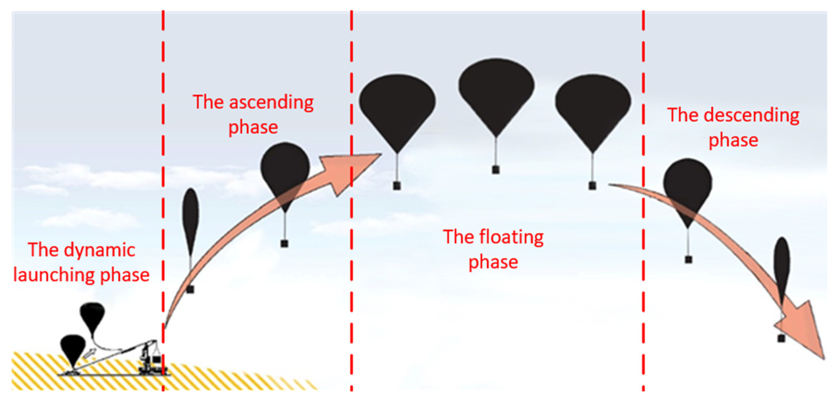
:1. Introduction
2. Environment Model
2.1. Atmospheric Model
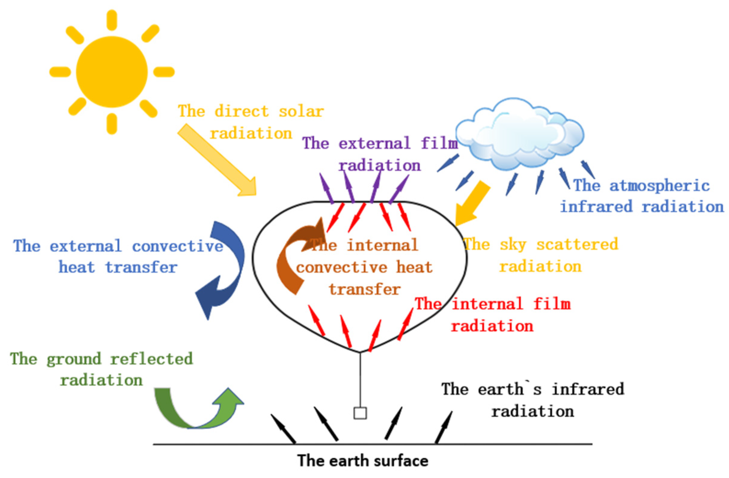
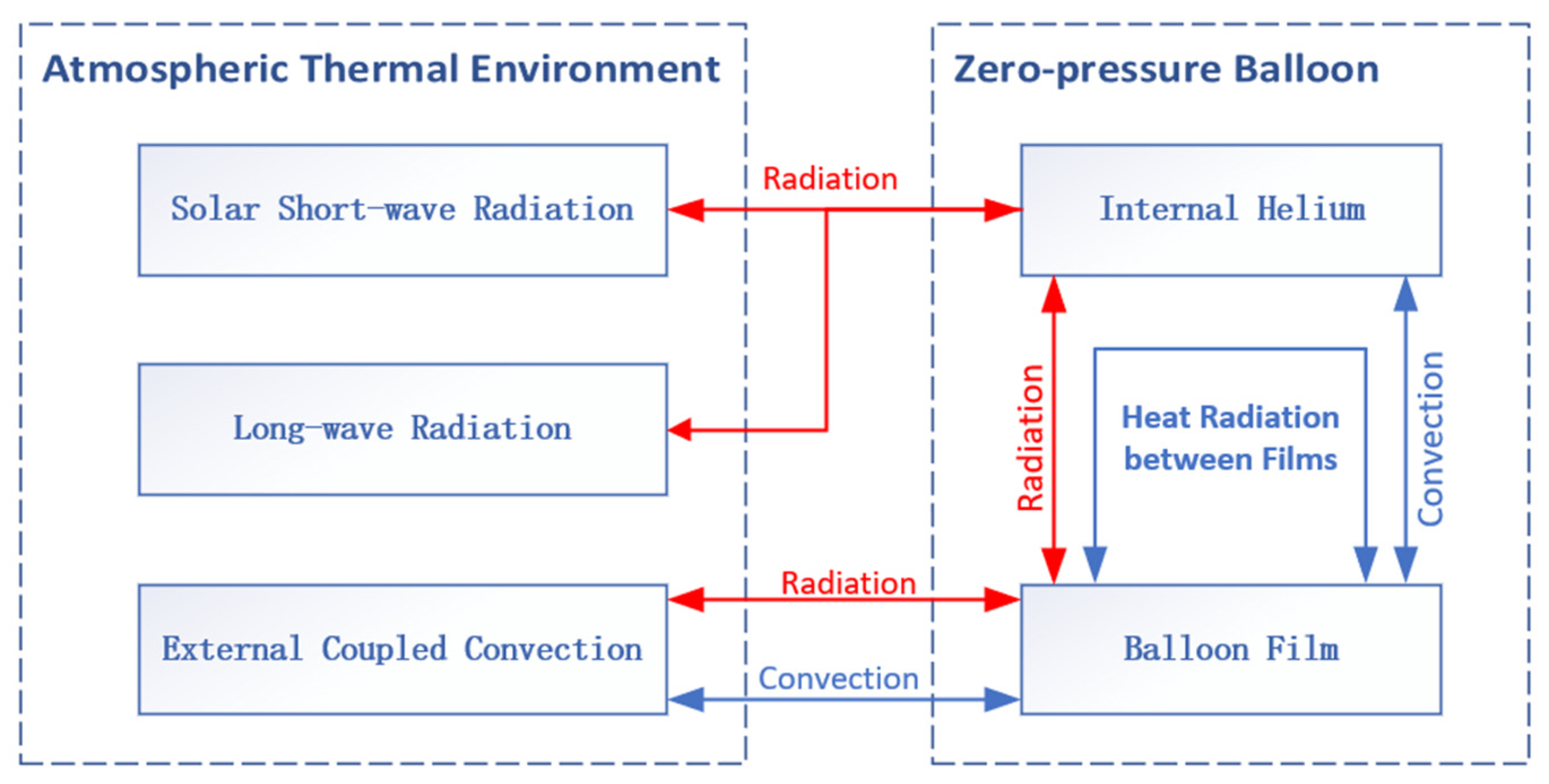
2.2. Thermal Model
2.2.1. Direct Solar Radiation
- solar elevation angle < 5°:
- solar elevation angle > 5°:
2.2.2. Ground-Reflected Radiation
2.2.3. Sky-Scattered Radiation
2.2.4. Earth’s Infrared Radiation
2.2.5. Atmospheric Infrared Radiation
2.2.6. Surface Thermal Radiation
2.2.7. Convective Heat Transfer
2.2.8. Heat Transfer on Balloon Film
2.2.9. Heat Transfer on Internal Helium
2.3. Earth Model
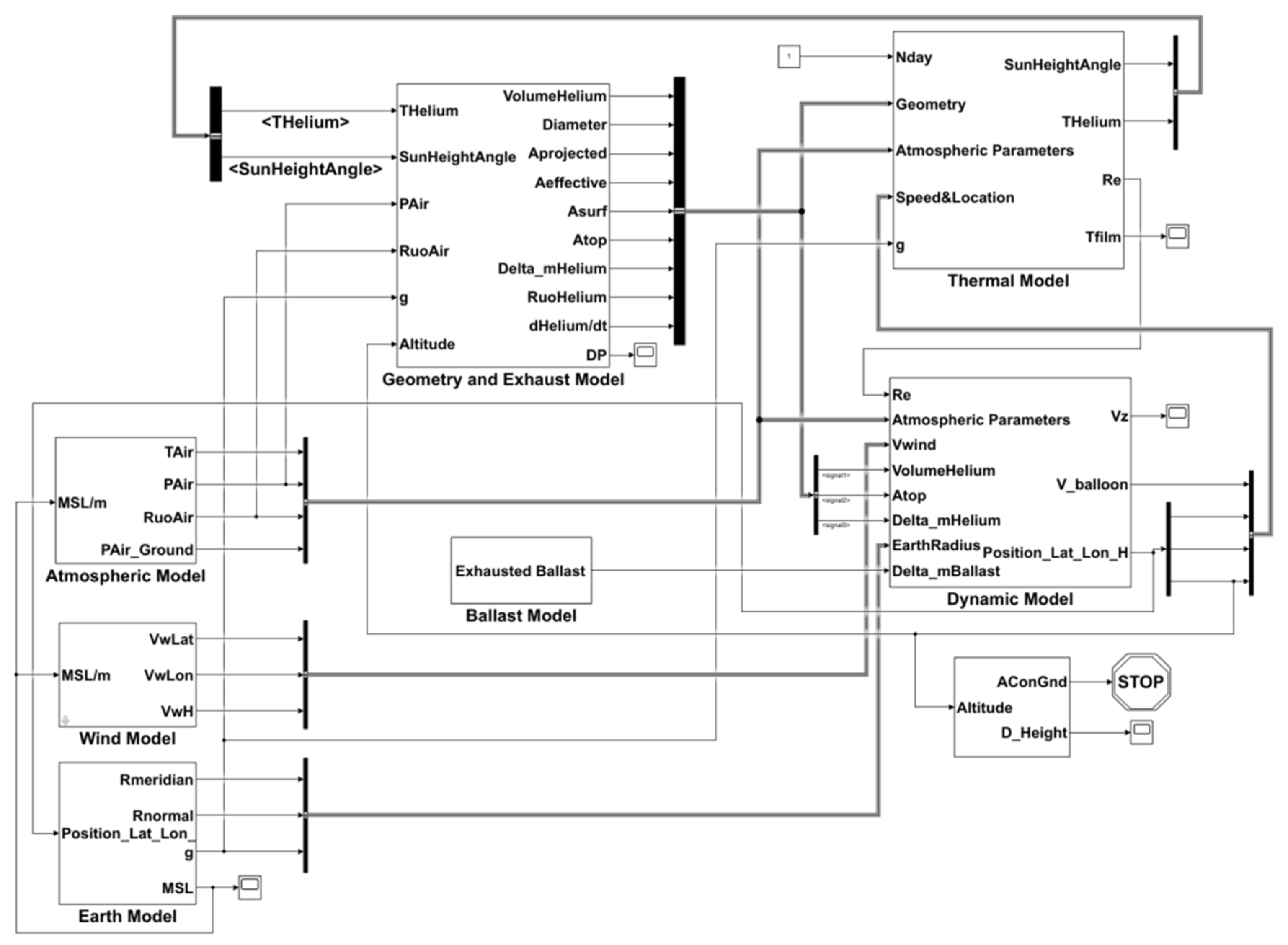
3. Trajectory Prediction Model
- (1)
- The horizontal components of the balloon’s speed are equal to the horizontal components of the wind’s speed.
- (2)
- The balloon is assumed to be a point mass when considering the external forces acting on the balloon.
- (3)
- The high-altitude wind speed magnitude and direction are assumed to be constant for at least 24 h.
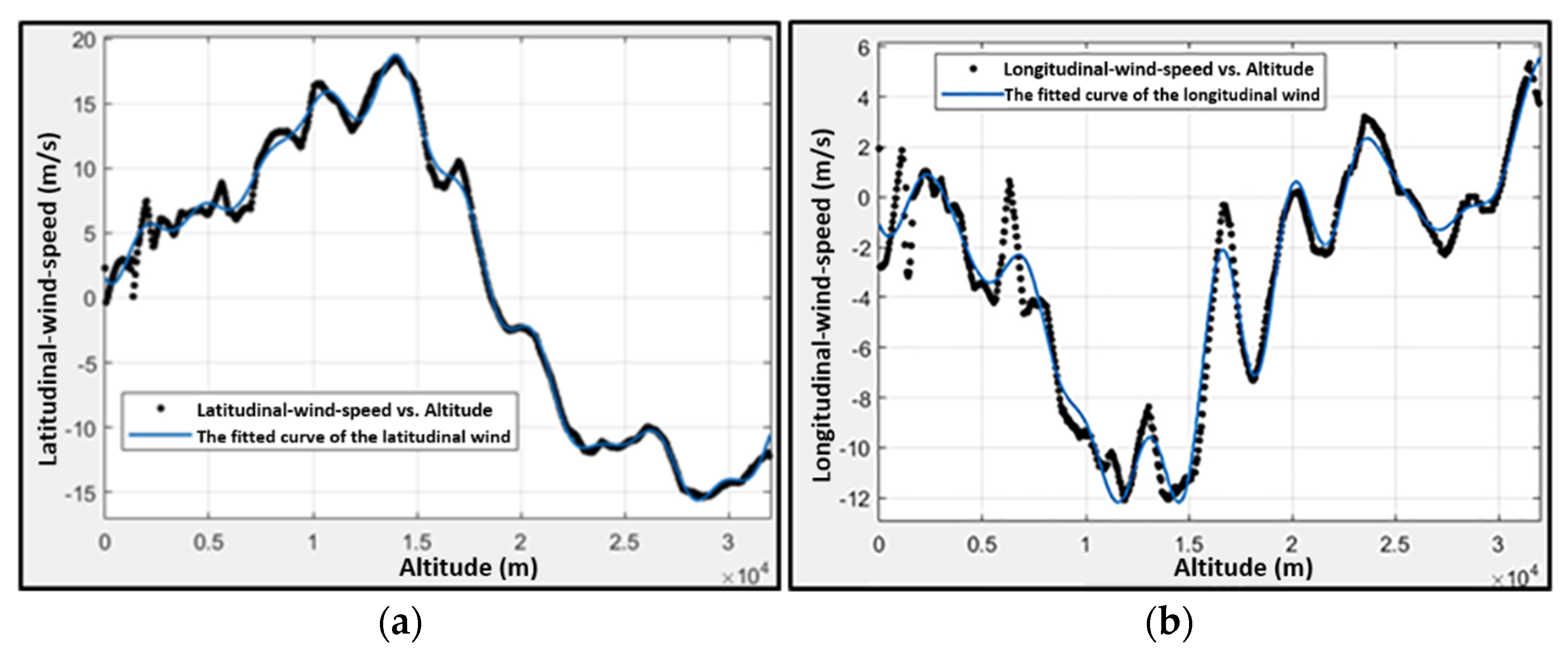
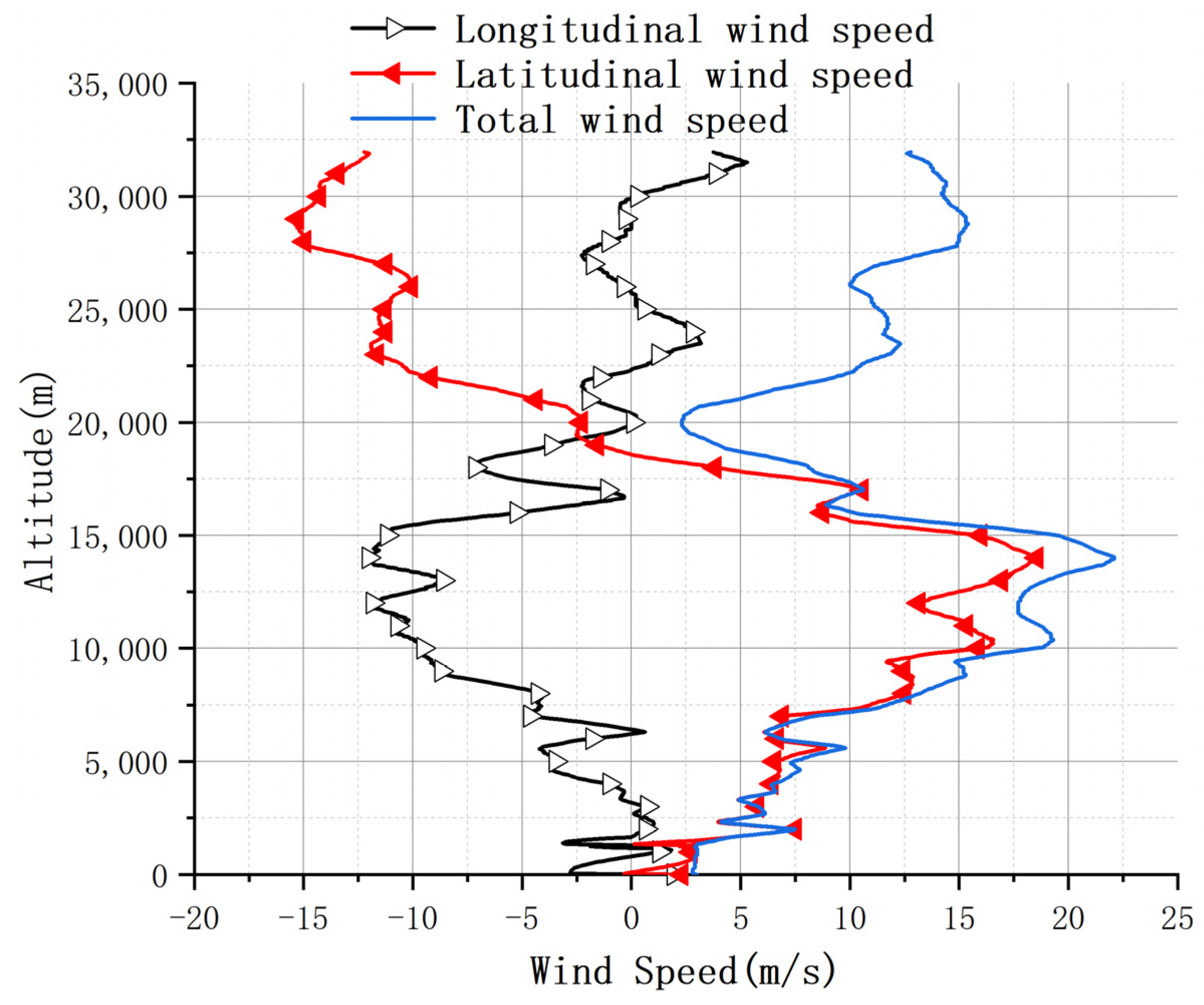
3.1. Wind Model
- (1)
- the fitted curve of the latitudinal wind speed (m/s) vs. altitude (m):
- (2)
- the fitted curve of the longitudinal wind speed (m/s) vs. altitude (m):
3.2. Geometry Model
- (1)
- diameter from the top view:
- (2)
- projected area from the top view:
- (3)
- During the balloon flight process, the illuminated projected area varies with the solar elevation angle, which is defined as
- (4)
- surface area of the zero-pressure balloon:
- (5)
- When the balloon is not fully inflated, the surface of the balloon is presented in crenellated form. The maximum crenellated surface area is defined as follows:
- (6)
- To better approximate a realistic situation for convection and film mass calculations, is used to describe the effective exposed surface area:
- (7)
- A zero-pressure balloon has a distinctive feature: the internal helium pressure is almost equal to the surrounding atmospheric pressure. The average pressure difference between the internal helium pressure and the surrounding atmospheric pressure is defined as
3.3. Dynamic Model
3.4. Exhaust Model
3.4.1. Automatic Exhaust Model
3.4.2. Active Exhaust Model
3.5. Ballast Model
4. Results and Discussion
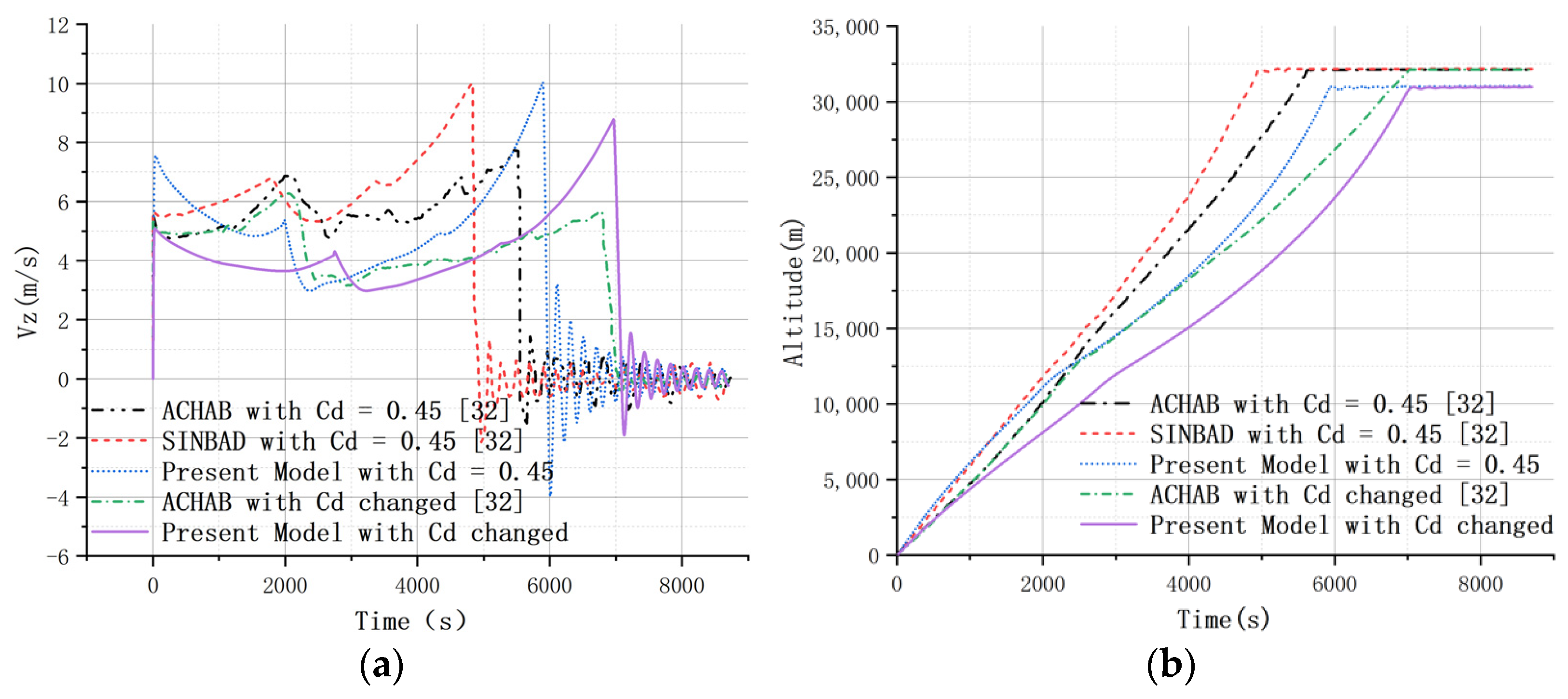
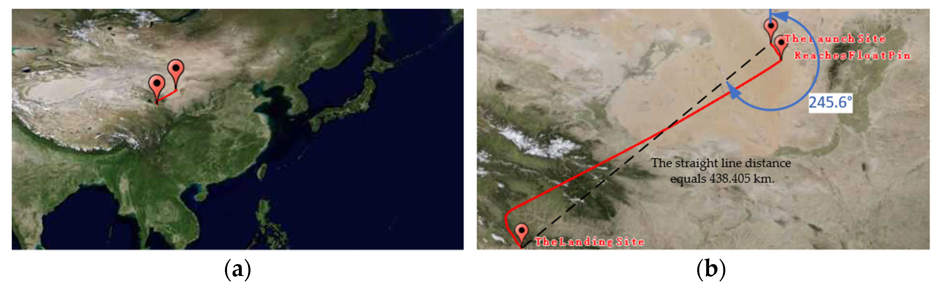
4.1. Model Validation
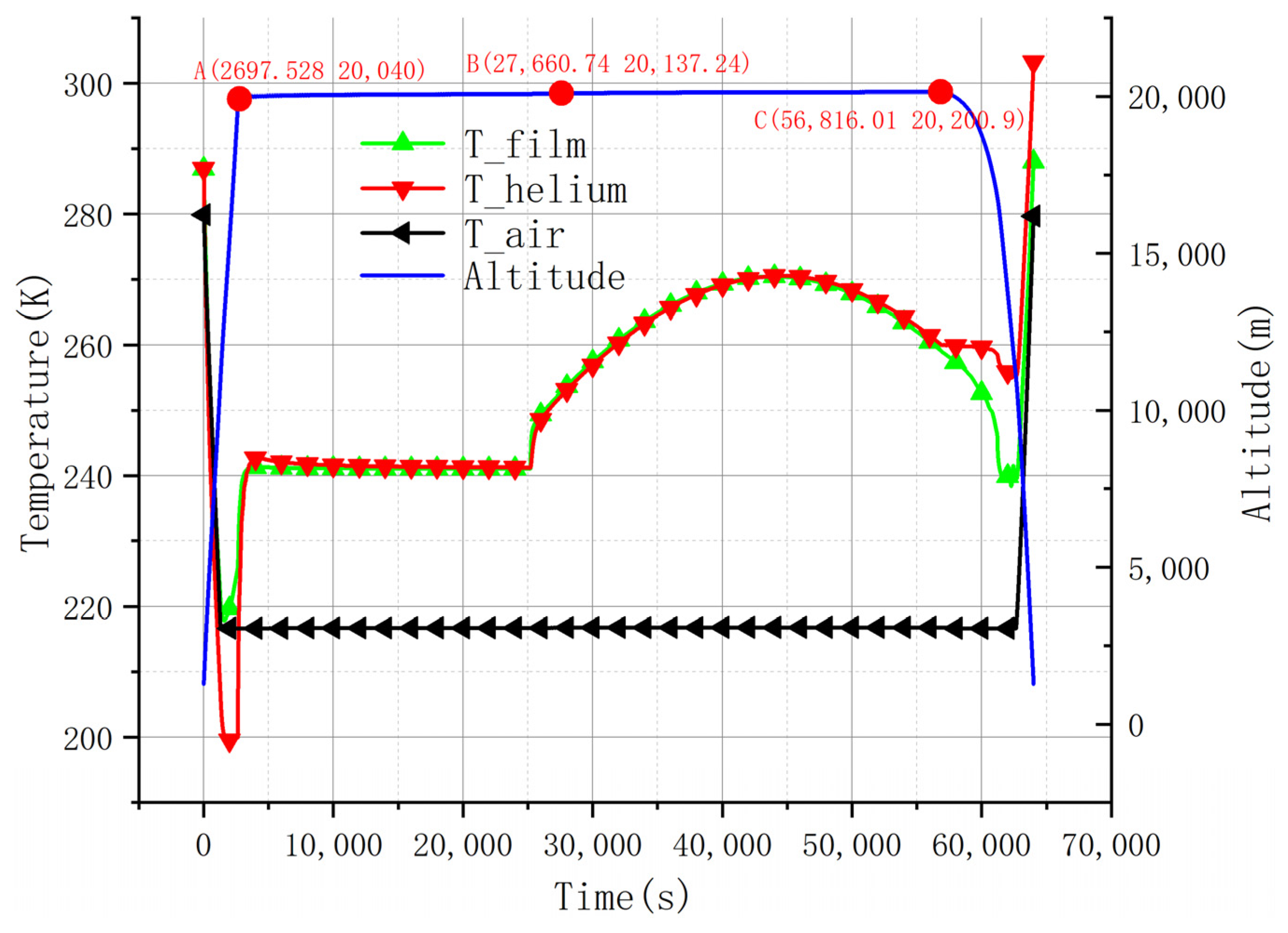
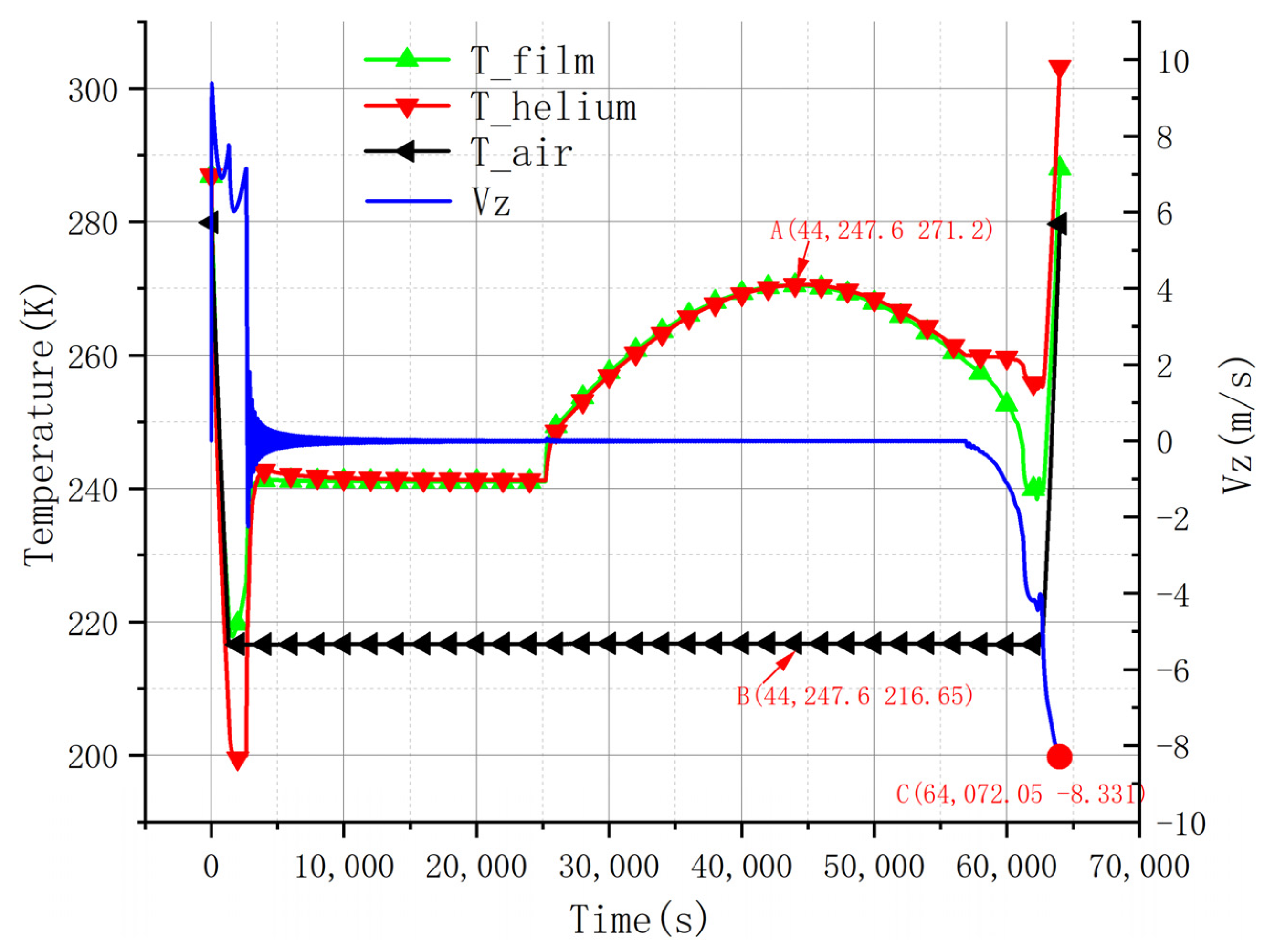
4.2. Flight Simulation
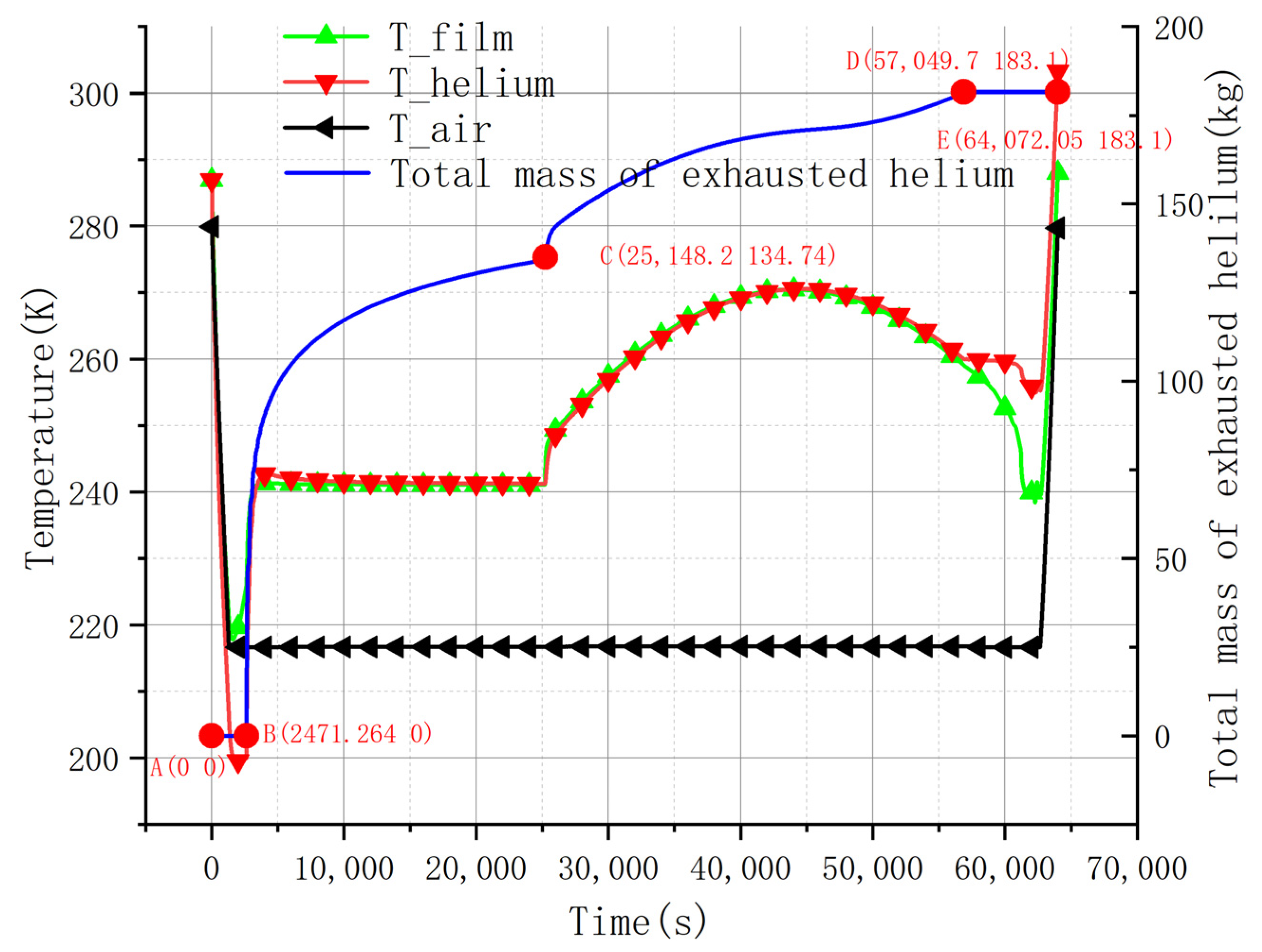
- Change Pattern of Temperature
- 2.
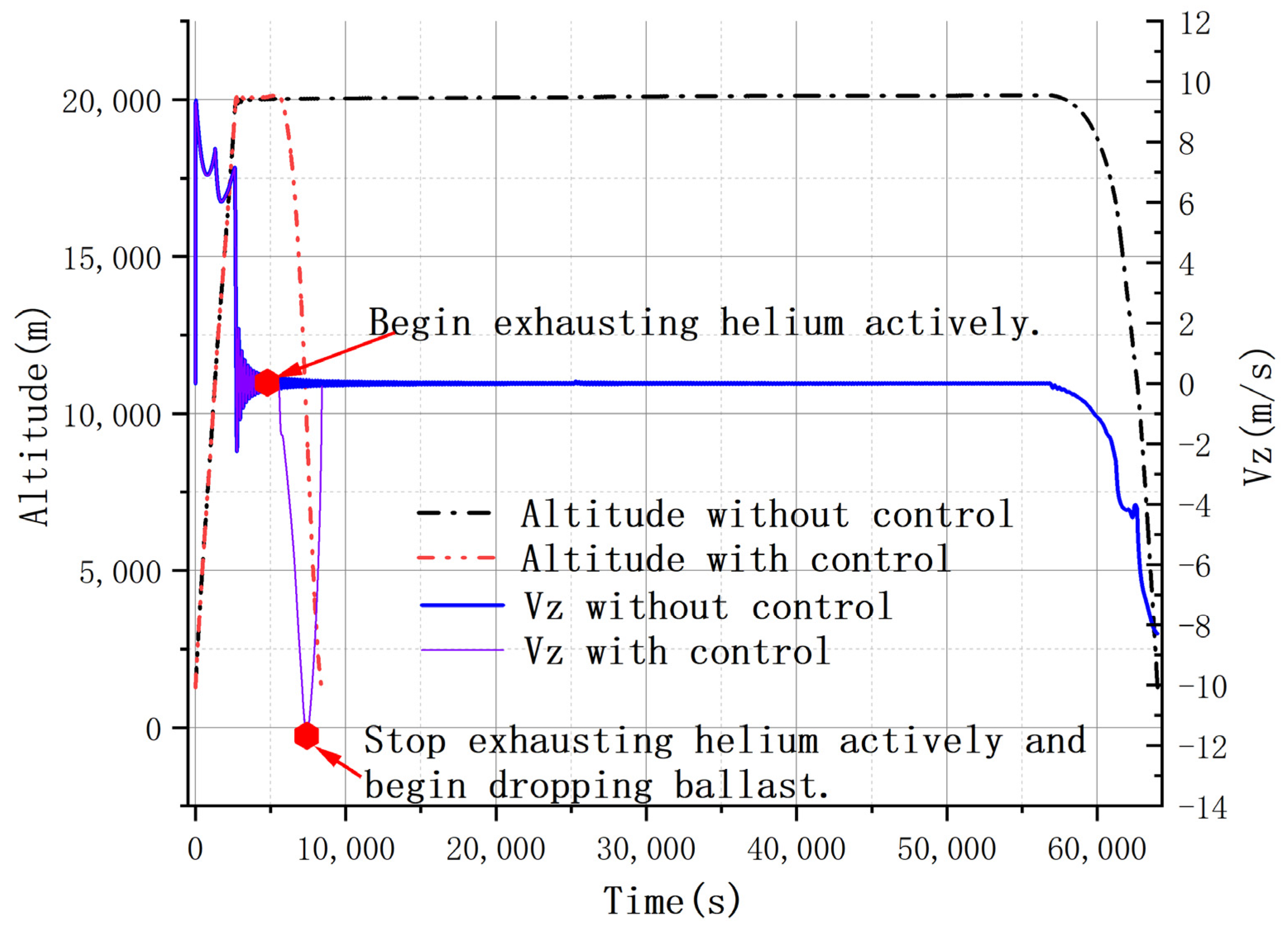
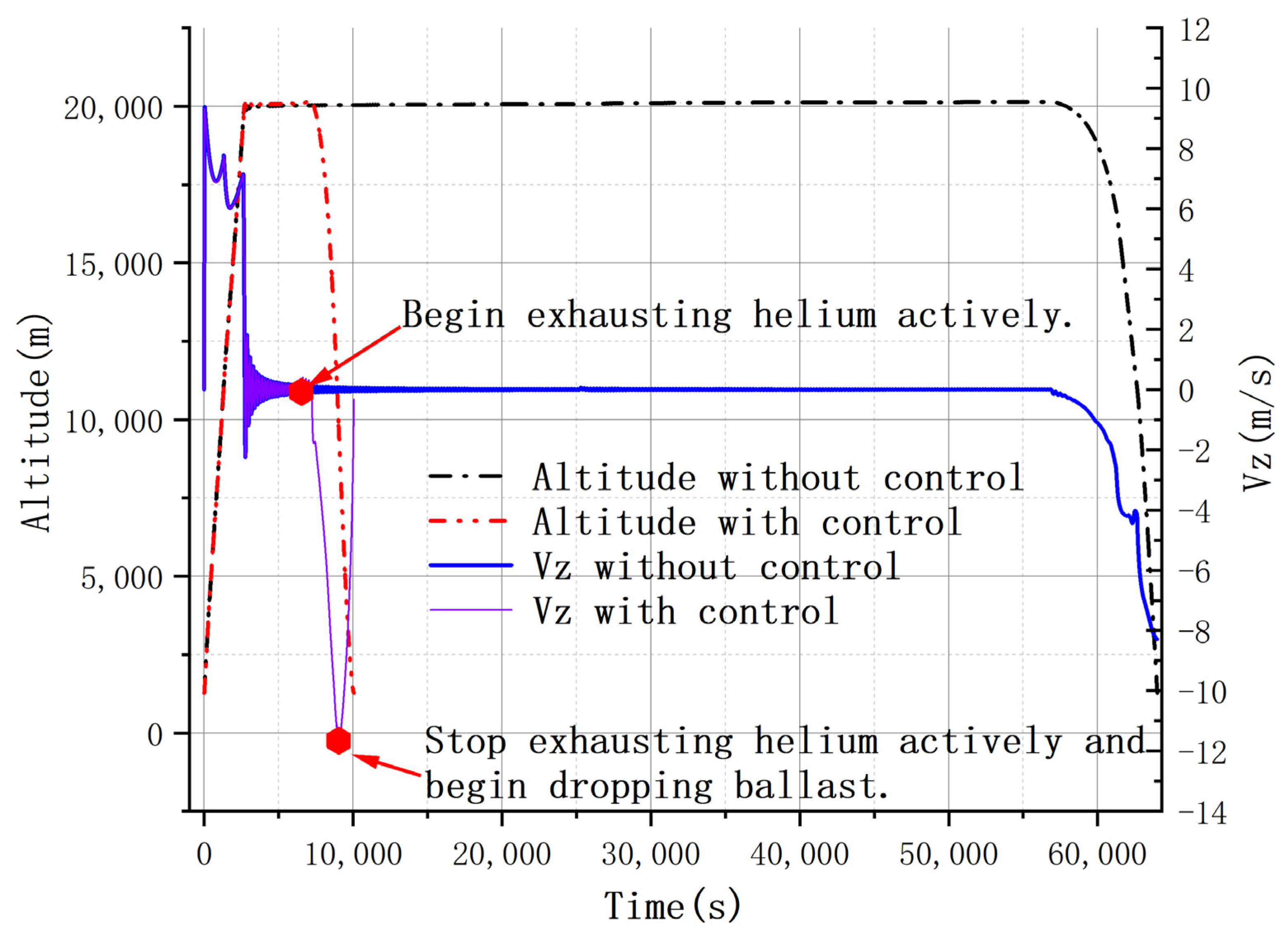
- Change Pattern of Altitude
- 3.
- Change Pattern of Vertical Speed
- 4.
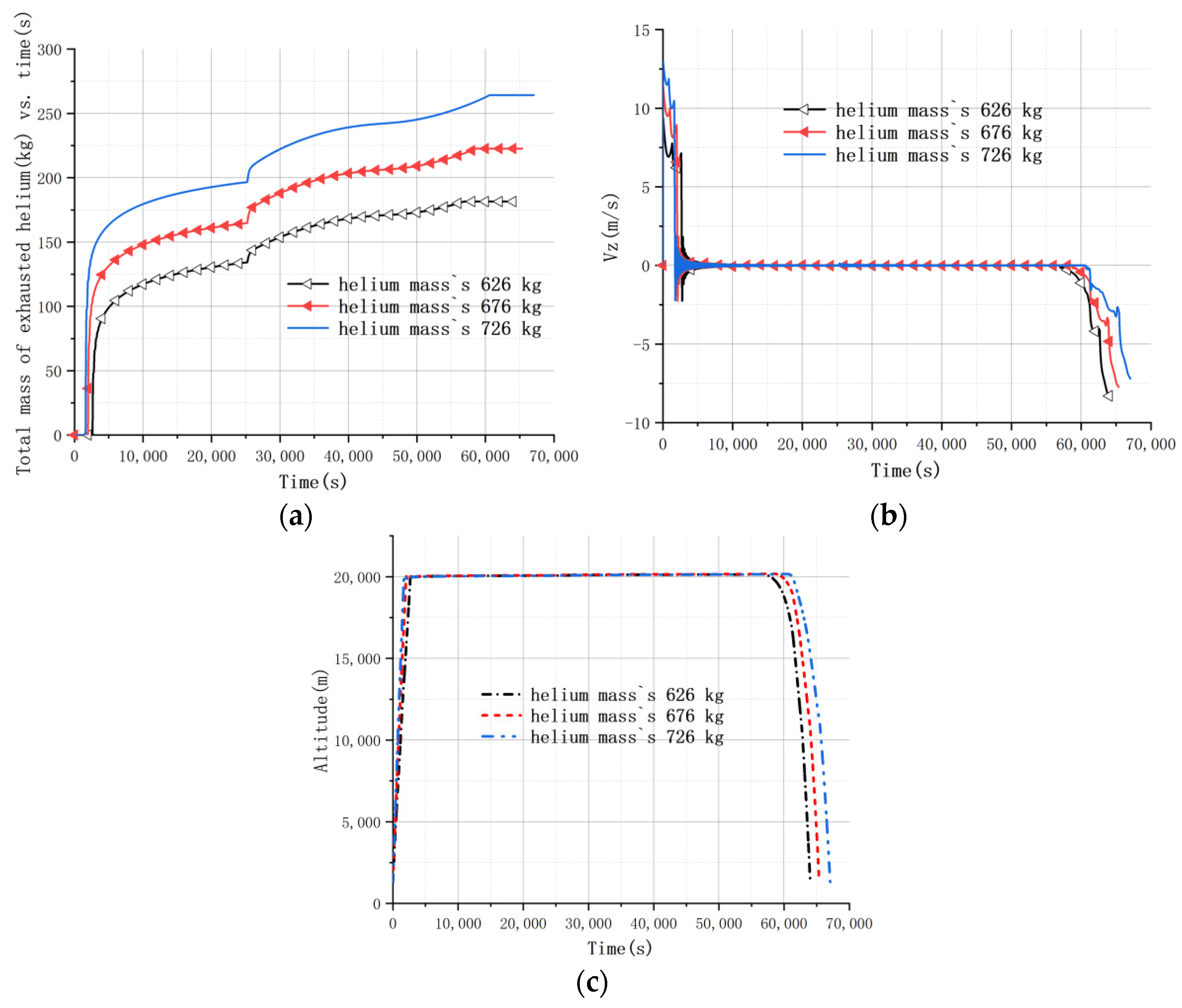
- Change Pattern of the Total Exhausted Mass of Helium
- 5.
- Trajectory Prediction
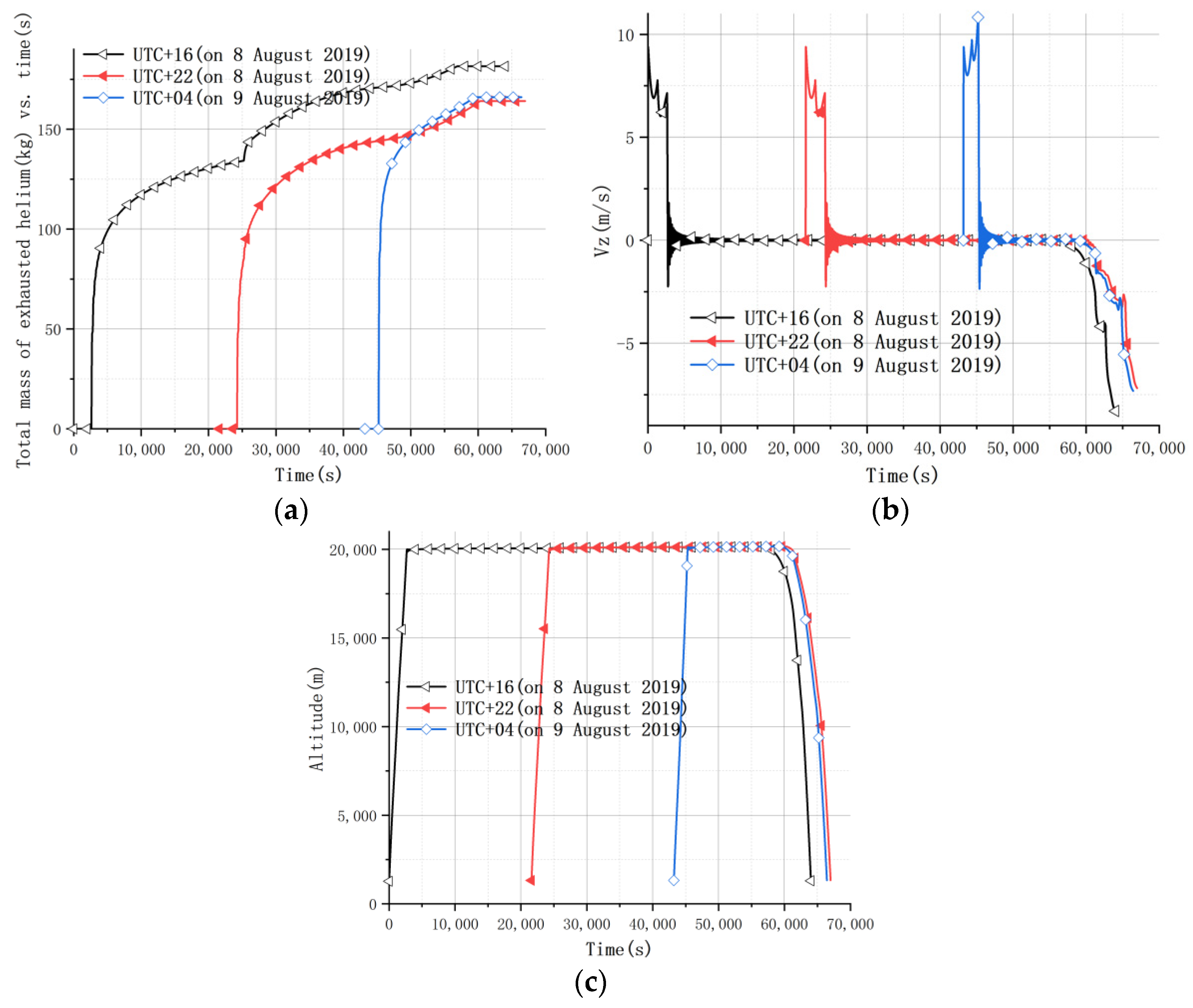
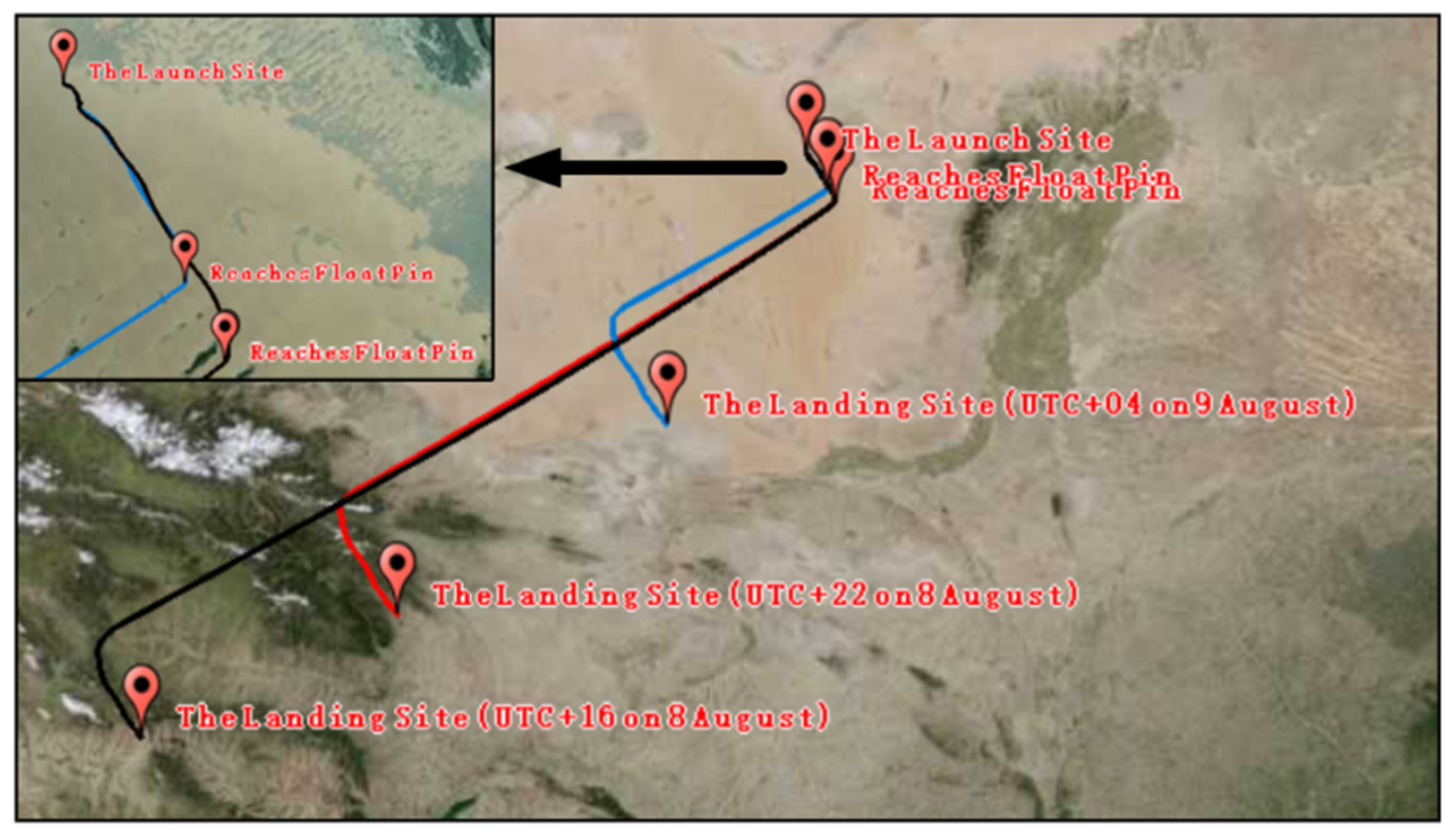
4.2.1. Launch Time
- The earlier the launch time, the more the total mass of helium is exhausted finally.
- The earlier the launch time, the smaller the vertical velocity during the accent phase, resulting in relatively low requirements for balloon structure design. This is because the faster the vertical speed, the more severe the supercooling phenomenon.
- The launch time has almost no effect on the floating altitude and landing vertical velocity.
- The earlier the launch time, the longer the flight time and flight distance. However, the maximum flight time is less than 24 h.
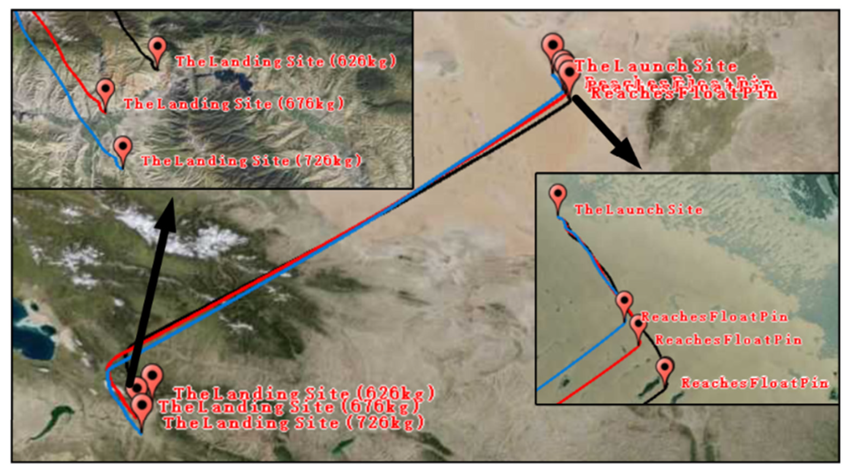
4.2.2. Initial Helium Mass
- The more the initial mass of helium, the more the mass of helium was exhausted. However, the mass of helium inside the balloon was the same when landing.
- The more the initial mass of helium, the faster the balloon system ascended.
- The initial mass of helium had no effect on the floating altitude and trajectory prediction.
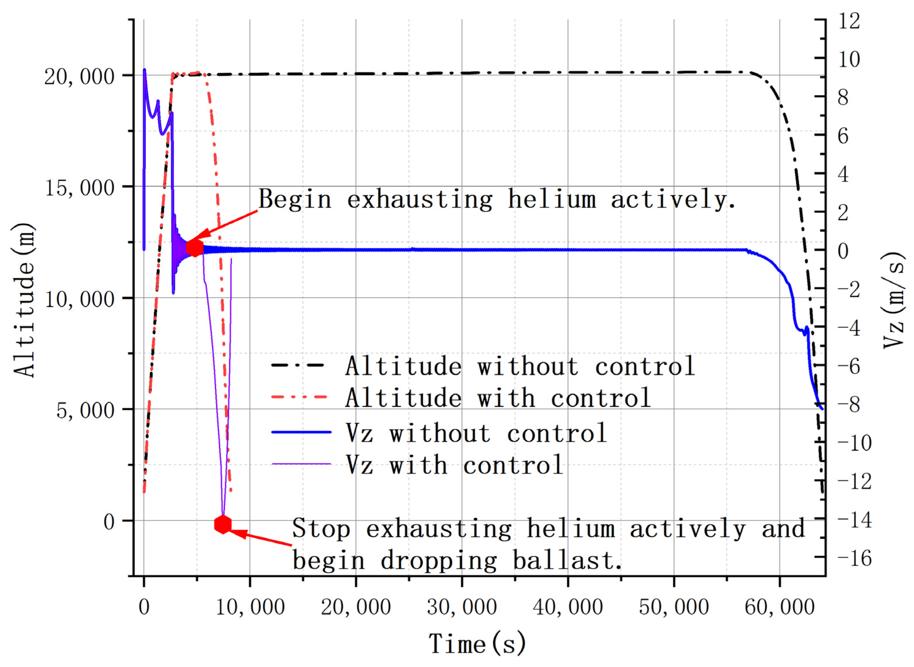
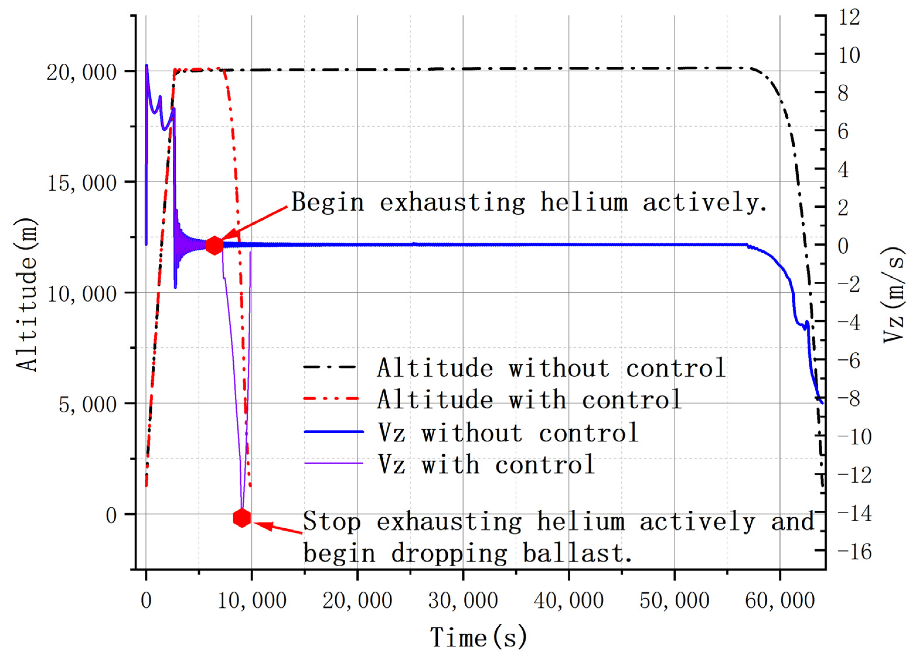
4.3. Trajectory Prediction with Control Strategy
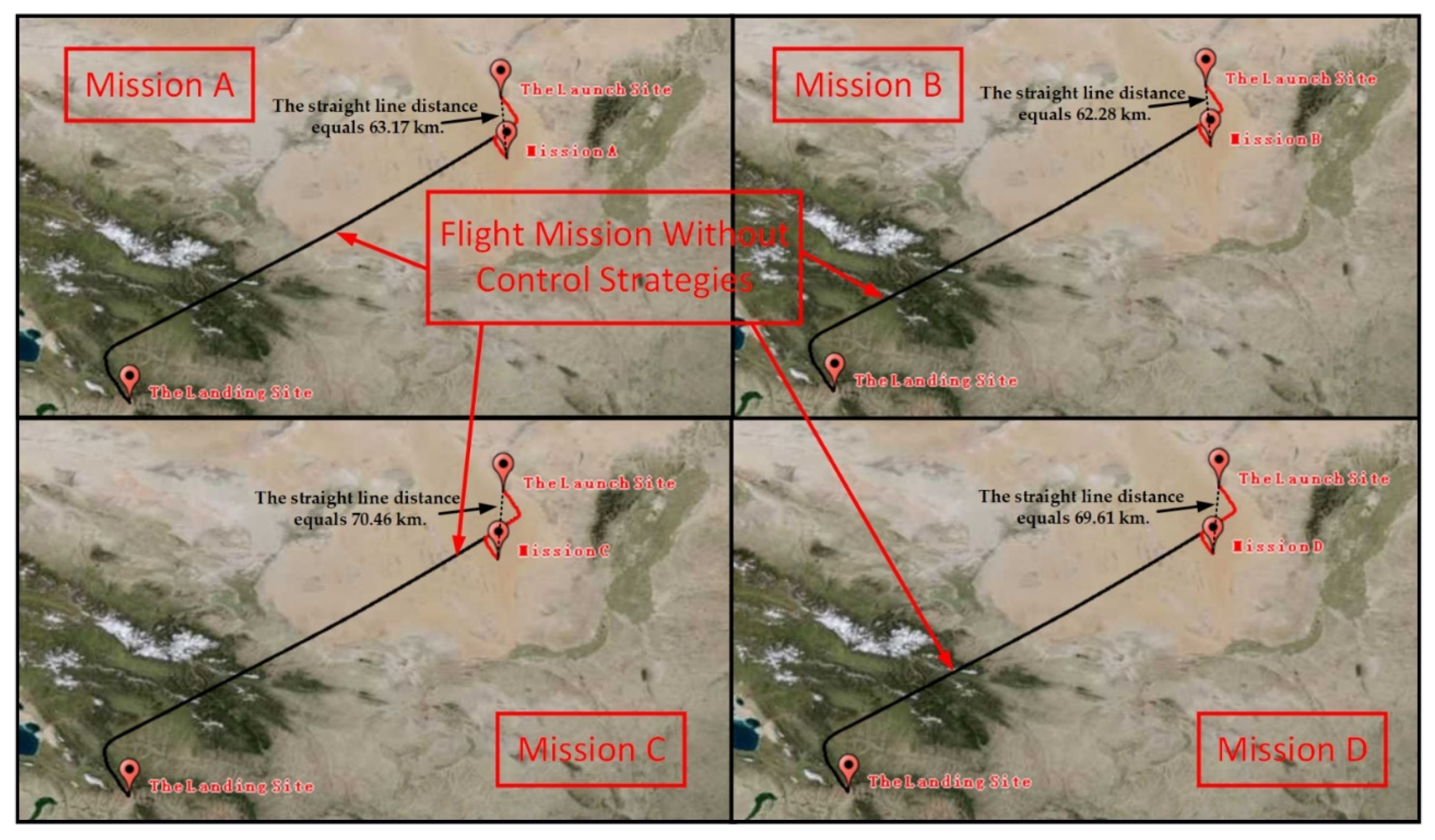
- With the control strategy applied, the flight time and lateral drift distance were greatly reduced. For Mission A, the straight-line distance was 63.17 km. For Mission B, the straight-line distance was 62.28 km, and for Mission C, the straight-line distance was 70.46 km. For Mission D, the straight-line distance was 69.61 km. For all the flight missions, the flight time was less than 3 h. Furthermore, the landing velocity could be reduced to near zero with the ballast dropped at the designed ballast drop altitude. However, for the situations that did not use the control strategies, the trajectory of the balloon system could not be controlled from the ground after launch. This can be a cause of potential accidents.
- The ballast flow rate mainly depended on the ballast drop altitude for each flight mission. The higher the ballast drop altitude, the smaller the ballast flow, which can help to design a ballast device. However, the higher the ballast drop altitude, the bigger the horizontal motion range, making recovery relatively more difficult.
5. Conclusions
- During the ascent phase, the vertical velocity takes on a W shape. By the time the balloon flight system reaches the designed float altitude, the vertical velocity decreases sharply to 0 m/s and oscillates around 0 m/s until it finally drops gradually to 0 m/s.
- During the ascent phase, the phenomenon of supercooling occurs, whereas the phenomenon of superheating occurs during the floating and descending phases. This information can help with balloon structure design.
- The launch time plays an important role in trajectory prediction and has a significant impact on flight performance. The results show that the earlier the launch time, the longer the flight time and flight distance. However, the maximum flight time is less than 24 h. Furthermore, the launch time has no effect on the floating altitude and landing vertical velocity.
- Maintaining the same launch time, changing the initial mass of helium has almost no effect on trajectory prediction. However, more helium filled on the ground will cause excessive vertical speed when ascending, leading to severe supercooling.
- Based on realistic flight mission requirements, the floating mission time, horizontal motion range, and landing speed must be taken into consideration. The exhaust helium valve and ballast drop device can be used together to plan the trajectory. The simulation results show that with control strategies applied, flight missions can be completed within limited airspace, and flight trajectories can be predicted to assist rapid and safe recovery and prevent harm from potential accidents.
- The ballast flow rate can be determined by the ballast drop altitude for each flight mission by experimentally dropping the ballast device before the balloon flight mission.
Author Contributions
Funding
Data Availability Statement
Conflicts of Interest
References
- Tang, J.; Duan, D.; Xie, W. Shape Exploration and Multidisciplinary Optimization Method of Semirigid Nearing Space Airships. J. Aircr. 2022, 59, 946–963. [Google Scholar] [CrossRef]
- Tang, J.; Wang, X.; Duan, D.; Xie, W. Optimisation and analysis of efficiency for contra-rotating propellers for high-altitude airships. Aeronaut. J. 2019, 123, 706–726. [Google Scholar] [CrossRef]
- Tang, J.; Xie, W.; Wang, X.; Chen, C. Simulation and Analysis of Fluid-Solid-Thermal Unidirectional Coupling of Near-Space Airship. Aerospace 2022, 9, 439. [Google Scholar] [CrossRef]
- Yamada, K.; Abe, T.; Suzuki, K.; Honma, N.; Koyama, M.; Nagata, Y.; Abe, D.; Kimura, Y.; Hayashi, A.K.; Akita, D.; et al. Deployment and flight test of inflatable membrane aeroshell using large scientific balloon. In Proceedings of the 21st AIAA Aerodynamic Decelerator Systems Technology Conference and Seminar, Dublin, Ireland, 23–26 May 2011; p. 2579. [Google Scholar]
- Jones, W.V. Evolution of scientific ballooning and its impact on astrophysics research. Adv. Space Res. 2014, 53, 1405–1414. [Google Scholar] [CrossRef]
- Randolph, T.M.; Mullenax, R.; Schwantes, C.; Sell, S.W.; Ball, D.R.J. The first balloon flight of the Low Density Supersonic Decelerator technology demonstration mission. In Proceedings of the 2015 IEEE Aerospace Conference, Big Sky, MT, USA, 7–14 March 2015; pp. 1–12. [Google Scholar]
- Qu, Z.; Li, C.; Hao, Y.; Yan, F.; Yang, Y. Project of high altitude balloon launched micro glider: Aircraft design, control and flight test. Int. J. Micro Air Veh. 2020, 12, 1756829320979955. [Google Scholar] [CrossRef]
- Gemignani, M.; Marcuccio, S. Dynamic characterization of a high-altitude balloon during a flight campaign for the detection of ISM radio background in the stratosphere. Aerospace 2021, 8, 21. [Google Scholar] [CrossRef]
- Farley, R. BalloonAscent: 3-D simulation tool for the ascent and float of high-altitude balloons. In Proceedings of the AIAA 5th ATIO and 16th Lighter-Than-Air System Technology and Balloon Systems Conferences, Arlington, VA, USA, 26–28 September 2005; p. 7412. [Google Scholar]
- Dai, Q.; Fang, X.; Li, X.; Tian, L. Performance simulation of high altitude scientific balloons. Adv. Space Res. 2012, 49, 1045–1052. [Google Scholar] [CrossRef]
- Sóbester, A.; Czerski, H.; Zapponi, N.; Castro, I. High-altitude gas balloon trajectory prediction: A Monte Carlo model. AIAA J. 2014, 52, 832–842. [Google Scholar] [CrossRef]
- Zhang, Y.; Liu, D. Influences of initial launch conditions on flight performance of high altitude balloon ascending process. Adv. Space Res. 2015, 56, 605–618. [Google Scholar] [CrossRef]
- Kayhan, Ö.; Yücel, Ö.; Hastaoğlu, M.A. Simulation and control of serviceable stratospheric balloons traversing a region via transport phenomena and PID. Aerosp. Sci. Technol. 2016, 53, 232–240. [Google Scholar] [CrossRef]
- Lee, Y.; Yee, K. Numerical prediction of scientific balloon trajectories while considering various uncertainties. J. Aircr. 2017, 54, 768–782. [Google Scholar] [CrossRef]
- Saleh, S.; He, W. Ascending performance analysis for high altitude zero pressure balloon. Adv. Space Res. 2017, 59, 2158–2172. [Google Scholar] [CrossRef]
- Waghela, R.; Yoder, C.D.; Gopalarathnam, A.; Mazzoleni, A.P. Aerodynamic Sails for Passive Guidance of High-Altitude Balloons: Static-Stability and Equilibrium Performance. J. Aircr. 2019, 56, 1849–1857. [Google Scholar] [CrossRef]
- Deng, X.; Yang, X.; Zhu, B.; Ma, Z.; Hou, Z. Analysis and simulation study of key technologies of intelligent stratospheric floatplane Loon. J. Aeronaut. 2022, 1–18. Available online: http://kns.cnki.net/kcms/detail/11.1929.V.20220710.1648.034.html (accessed on 2 August 2022).
- Atmosphere, US Standard. US Standard Atmosphere; National Oceanic and Atmospheric Administration: Washington, DC, USA, 1976.
- Cathey, H.M. Advances in the thermal analysis of scientific balloons. In Proceedings of the 34th Aerospace Sciences Meeting and Exhibit, Reno, NV, USA, 15–18 January 1996. [Google Scholar]
- Cheng, C.; Wang, X. Thermodynamic model of airship considering skin transmittance and its thermal characteristics. J. Shanghai Jiaotong Univ. 2021, 55, 868–877. [Google Scholar]
- Dai, Q. Study on Thermal Environment and Thermal Characteristics of Airships. Ph.D. Dissertation, Nanjing University of Aeronautics and Astronautics, Nanjing, China, 2014. [Google Scholar]
- Li, X.; Fang, X.; Dai, Q. Research on thermal characteristics of photovoltaic array of stratospheric airship. J. Aircr. 2011, 48, 1380–1386. [Google Scholar] [CrossRef]
- Yang, X.; Hou, Z.; Ma, Z. Analysis of influential factors to supercooling phenomenon during ascent stage of stratospheric long duration balloons. J. Natl. Univ. Def. Technol. 2015, 3i7, 91–96. [Google Scholar]
- Kreider, J.F. Mathematical modeling of high altitude balloon performance. In Proceedings of the 5th Aerodynamic Deceleration Systems Conference, Albuquerque, NM, USA, 17–19 November 1975; p. 1385. [Google Scholar]
- Rogers, R.M. Applied Mathematics in Integrated Navigation Systems; American Institute of Aeronautics and Astronautics, Inc.: Reston, VA, USA, 2000; ISBN 1-56347-397-6. [Google Scholar]
- Sum of Sine Models. Available online: https://ww2.mathworks.cn/help/curvefit/sum-of-sine.html (accessed on 2 August 2022).
- Robyr, J.-L.; Bourquin, V.; Goetschi, D.; Schroeter, N.; Baltensperger, R. Modeling the vertical motion of a zero pressure gas balloon. J. Aircr. 2020, 57, 991–994. [Google Scholar] [CrossRef]
- Lv, M.; Wu, Z. Thermodynamic model and numerical simulation of high altitude balloon ascending process. J. Beijing Univ. Aeronaut. Astronaut. 2011, 37, 505–509. (In Chinese) [Google Scholar]
- Farrell, J.A.; Barth, M. The Global Positioning System & Inertial Navigation; McGraw Hill: New York, NY, USA, 1999; ISBN 0-07-022045-X. [Google Scholar]
- Yajima, N.; Izutsu, N.; Imamura, T.; Abe, T. Scientific Ballooning: Technology and Applications of Exploration Balloons Floating in the Stratosphere and the Atmospheres of Other Planets; Springer Science & Business Media: Berlin/Heidelberg, Germany, 2009; Volume 112. [Google Scholar]
- Garde, G. Comparison of two balloon flight simulation programs. In Proceedings of the AIAA 5th ATIO and16th Lighter-Than-Air System Technology and Balloon Systems Conferences, Arlington, VA, USA, 26–28 September 2005; p. 7413. [Google Scholar]
- Palumbo, R. A Simulation Model for Trajectory Forecast, Performance Analysis and Aerospace Mission Planning with High Altitude Zero Pressure Balloons. Ph.D. Dissertation, University of Naples “Federico II”, Naples, Italy, 2008. [Google Scholar]


| Parameter | Value |
|---|---|
| Maxi volume | 44,930.5 m3 |
| Lifting gas (helium) mass | 626.5 kg |
| Balloon mass | 487 kg |
| Suspending mass (payload) | 2930.87 kg |
| Initial film temperature | 286.95 K |
| Initial helium temperature | 286.95 K |
| Number of the helium exhaust valves | 2 |
| Film absorption factor of solar radiation | 0.33 |
| Film transmissivity factor of solar radiation | 0.65 |
| Film absorption factor of infrared radiation | 0.75 |
| Film transmissivity factor of infrared radiation | 0.20 |
| Film average infrared emissivity factor | 0.75 |
| Earth surface reflectance factor | 0.3 |
| Ground average infrared emissivity factor | 0.95 |
| Launch date and time | 8 August 2019 (UTC +16) |
| Launch base | Lat: 39°, Lon: 105° |
| Target altitude | 20 km |
| Ground air pressure | 101,325 Pa |
| Ground air temperature | 288.15 K |
| Flight Mission | Floating Time (min) | Ballast Drop Altitude (km) | Ballast Flow Rate (kg·s−1) |
|---|---|---|---|
| Mission A | 30 | 10 | 1.023 |
| Mission B | 30 | 8 | 1.671 |
| Mission C | 60 | 10 | 1.024 |
| Mission D | 60 | 8 | 1.672 |
Publisher’s Note: MDPI stays neutral with regard to jurisdictional claims in published maps and institutional affiliations. |
© 2022 by the authors. Licensee MDPI, Basel, Switzerland. This article is an open access article distributed under the terms and conditions of the Creative Commons Attribution (CC BY) license (https://creativecommons.org/licenses/by/4.0/).
Share and Cite
Tang, J.; Pu, S.; Yu, P.; Xie, W.; Li, Y.; Hu, B. Research on Trajectory Prediction of a High-Altitude Zero-Pressure Balloon System to Assist Rapid Recovery. Aerospace 2022, 9, 622. https://doi.org/10.3390/aerospace9100622
Tang J, Pu S, Yu P, Xie W, Li Y, Hu B. Research on Trajectory Prediction of a High-Altitude Zero-Pressure Balloon System to Assist Rapid Recovery. Aerospace. 2022; 9(10):622. https://doi.org/10.3390/aerospace9100622
Chicago/Turabian StyleTang, Jiwei, Shumin Pu, Peixi Yu, Weicheng Xie, Yunfei Li, and Binxing Hu. 2022. "Research on Trajectory Prediction of a High-Altitude Zero-Pressure Balloon System to Assist Rapid Recovery" Aerospace 9, no. 10: 622. https://doi.org/10.3390/aerospace9100622
APA StyleTang, J., Pu, S., Yu, P., Xie, W., Li, Y., & Hu, B. (2022). Research on Trajectory Prediction of a High-Altitude Zero-Pressure Balloon System to Assist Rapid Recovery. Aerospace, 9(10), 622. https://doi.org/10.3390/aerospace9100622