Abstract
By combining the flapping and rotary motion, a flapping wing rotor (FWR) shows unique kinematics of motion. It can produce a significantly higher aerodynamic efficiency and lift coefficient than insect-like flapping wings. However, due to the lack of controllable FWR aerial vehicles, the effect of different flapping parameters of the FWR on aerodynamic characteristics and efficiency remains to be evaluated experimentally. In this work, we conduct experimental studies to investigate the FWR’s lift performance based on our previous vehicle design, which has demonstrated sustained stable hover and maneuver. In particular, by using such flyable FWR as the test platform, the changes in attack angle of the wing, the torsion of wings, different neutral positions, different up and down flapping angles, and different flapping amplitudes, were studied respectively. CFD simulation was used as an auxiliary and supplementary means for validation. As a result, design essentials to lift maximization of the FWR are proposed. The result proves that changing the attack angle and the torsion of the wing will have a certain impact on the lift. In addition, the ideal lift force can be generated when the neutral position tend to zero degrees and the up and down flapping angles tend to be equal. With the growth of the flapping amplitude, the lift force increases continuously. These experimental results provide important design cues for maximizing lift and payload capability of FWR-MAVs.
1. Introduction
The micro aerial vehicle (MAV) concept was first proposed by the U.S. Defense Advanced Research Project Agency (DARPA) 30 years ago [1], which imposed limits on the size and weight of such vehicles. Due to the limitations, most of the initial designs were fixed wing aircraft, such as AeroVironment’s “Black Widow” [2] and Lockheed Martin’s “MicroStar” [3]. Both of them had remote control flight capability and certain endurance, but the fixed wing flight mode greatly limited their mission flexibility. In the next few years, with the development of the microcontroller unit (MCU) and control algorithms, many rotary-wing MAVs with hovering ability appeared. The “Black Hornet”, developed by Norway’s ProxDynamics, stands out as the smallest commercial UAV system, weighing 16 g [4], but the added tail rotor required to balance the torque increased the overall size and complexity.
Due to the high aerodynamic efficiency and various lift mechanism of a flapping wing at low Reynolds number, the micro flapping wing MAVs, which directly mimic the flapping creatures, have developed rapidly [5,6,7]. Phan et al. [8] designed a stable 21 g insect-like tailless flapping wing MAV, which equips three steering gears to adjust wing kinematics and realizes stable hovering within a 0.3 m ground radius. Tu et al. [9] used motors to drive the wing directly, and realized the stable flight by precise motion control of a pair of bio-inspired decoupled wings. Ma et al. [10] built an 80 mg flapping-wing robot modeled on the morphology of flies and demonstrated constrained stable hovering and basic controlled flights, and they achieved an untethered flight of an improved flapping-wing robot in 2019 [11]. Wagter et al. [12] designed DelFly Explorer—a 20 g flapping-wing MAV, which integrates a 0.98 g autopilot and a 4 g onboard stereo vision system to perform autonomous flight. Karásek et al. [13] in the same research team built DelFly Nimble, a tailless flapping wing MAV that demonstrates high maneuverability in flight.
To date, the state-of-the-art flapping wing MAVs’ still cannot match the flight performance of their natural counterparts. In order to further push the aerodynamic efficiency of MAVs, Guo et al. [14] integrated the advantages of flapping and rotary wings, and then proposed an alternative concept -the flapping wing rotor (FWR), in which wings of a conventional flapping wing MAV are converted to a center symmetrical installation. The momentum produced by the flapping motion thrust drives the wings to rotate around the central axis so that both the flapping motion and the rotation of the wings produce the lift required to overcome the vehicle weight for VTOL and hovering. The FWR has the advantages of significantly higher aerodynamic efficiency and lift coefficient than insect-like wings, in the range of Reynolds number from 2600 to 5000, and ideal Strouhal number around 0.3 [15,16]. Li et al. employed a quasi-steady method to compare the efficiency and lift of the flapping wing, rotary wing, and flapping wing rotor, and confirmed that the rotary wing shows the greatest efficiency, while flapping wing rotor can obtain both relatively high lift and relatively high efficiency at the same time [17].
Through computational fluid dynamics (CFD) simulations, the flow mechanism of the FWR coupled with flapping motion and rotary motion is further understood. Wu et al. used CFD method to analyze the unsteady aerodynamic behavior of such a layout of a low Reynolds number, and proposed that the lift and rotational moment will increase with the increase in pitching amplitude and Reynolds number [18]. Wang et al. studied an FWR of aspect ratios of five by CFD method and proposed that a higher Reynolds number and mean pitching angle can strengthen the leading edge vortex and provide a higher lift and thrust [19]. Shao et al. propose the concept of chord wise curved wing used on an FWR, and studied the influence of maximum radian height and maximum radian position on lift force through numerical simulation [20]. However, all these studies were mainly based on CFD simulation and exploration of the aerodynamic mechanism of the FWR, lacking sufficient experimental verification.
In 2017, RotorBee, developed by Beihang University, China, became the world’s first FWR to achieve vertical take-off with power [21]. This was followed in 2019 by the three-wing FWR, which achieved self-stabilizing control and remote-controlled flight [22], which is chosen as the test platform in this work.
The design and fabrication of FWR-MAVs is limited by mechanical imperfections and assembly asymmetries, and the flight quality of the FWR cannot be as ideal and stable as in CFD simulation or ground bench experiments. Therefore, most of the previous studies on FWR are based on CFD simulation or experiments with FWR mechanisms lacking sustained flight capability. It is desired to perform studies capable of simultaneously understanding the lift characteristics of the FWR and guaranteeing its controllable flight.
This paper investigates the influences of five different flapping parameters on FWR based on the propulsion system of the world’s first controlled three-wing FWR as presented in [22]. The flapping parameters are the attack angle of the wings, the torsion of wings, the flapping neutral positions, the maximum angles of flapping up and down, and the flapping amplitudes. These parameters were inadvertently changed from the previous production, and the flight quality of the aircraft also changed accordingly. These parameters are also relatively easy to adjust. Considering that an FWR is the same as most flapping-wing MAVs, increasing the flapping frequency can increase the lift without considering the mechanical and transmission problems, so a comparative study is carried out by increasing the flapping frequency to check the varying trend of lift. The CFD simulation is used as an auxiliary and supplementary means, because it needs to experimentally determine the corresponding relationship between the flapping frequency and the rotational speed under different working conditions to carry out the UDF programming and setting motion. Therefore, it is mainly used to verify the flutter under some parameters or to predict and supplement, with high confidence, some unreachable experimental conditions. As a result, a couple of important findings are summarized as follows: 1. Changing the attack angle and the torsion of the wing will have a certain impact on the lift; 2. The ideal lift force can be generated when the neutral position tend to zero degrees and the up and down flapping angles tend to be equal; 3. With the growth of the flapping amplitude, the lift force increases continuously.
The rest of the article is organized as follows. Section 2 describes the FWR-MAV, especially the wing structure and flapping rotary mechanism. Section 3 shows the flapping wing rotor experimental system and the CFD model. Section 4 shows the experimental results of five different flapping parameters and the causes of the lift force changes is also discussed. Section 5 summarizes this work.
2. Vehicle Description
The three-wing FWR-MAV consists of three parts: the lift generating system, attitude control mechanism and avionic system, as shown in Figure 1. The lift generating system mainly generates active flapping motion, passive rotation motion, and passive torsion of the wings to gain lift force, as shown in Figure 2. The attitude control mechanism is designed to improve the stability and control the attitude of the MAV. The avionic system senses the MAV’s attitude and receives remote signals, and then outputs control signal to control the brushless motor and steering gear deflection angle.
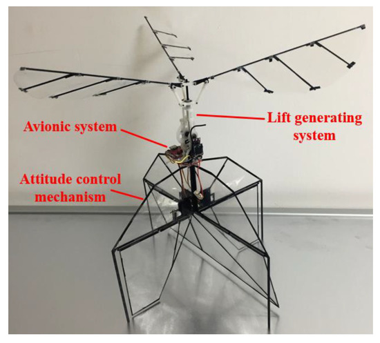
Figure 1.
Three-wing FWR-UAV.
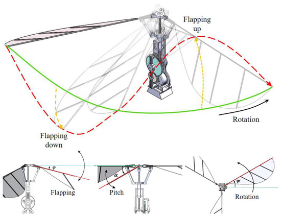
Figure 2.
The lift generation system and the active flapping, passive rotation, and passive torsion of the wings.
The FWR-UAV achieves takeoff with its own battery, and realizes automatic stability control with the flight control system. As shown in Figure 3, it can perform stable hover flight.
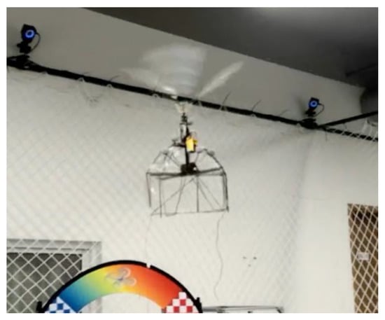
Figure 3.
FWR-UAV stable hover flight.
In this investigation, a three-wing FWR experimental prototype, based on the lift generating system of the FWR-MAV, was designed and built in the configuration illustrated. It also consists of two parts: flapping wings and driving mechanism. The frame of the model was manufactured by 3D printing in order to guarantee the precision of processing and assembly. Compared with the prototype flight FWR, the frame of this model was specially strengthened, though the drive forms were identical.
The wing of the FWR consists of a carbon fiber main beam, three carbon fiber auxiliary beams and a thin polyethylene film wing surface (Figure 4). The root of the wing is installed on the wing root part cut from carbon fiber board, and the attack angle of the wing is formed by the angle between the wing surface and the installation plane of the wing root part (Figure 5). In previous research, all three auxiliary beams were on the same plane. The FWR has some aerodynamic characteristics similar to the rotary wing, so adding torsion to the wings of the FWR such as the screw blade might also obtain better aerodynamic performances. In order to explore the influence of wing torsion, special molds are used to place auxiliary beams in different planes, then the torsional wing is obtained (Figure 6).
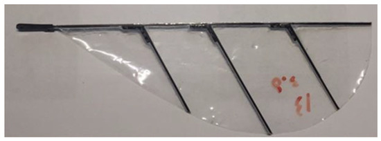
Figure 4.
The rigid wing of the FWR without torsion.
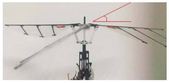
Figure 5.
The attack angle of the wing.
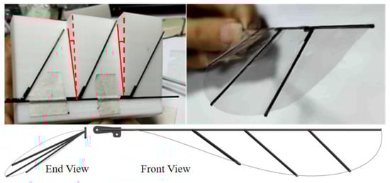
Figure 6.
The flexible torsional wing and its processing methods.
The flapping rotary mechanism of this prototype is a combination of crank-chute mechanism and four-bar linkage mechanism, as shown in Figure 7. The gear drives the crank to rotate, and the crank-chute mechanism converts the rotary motion of the crank to the reciprocating motion of the slide bar. The upper support is fixed at the top of the slide rod, while the lower support is fixed at the top of the sleeve. Through the transmission of wing root parts and connecting bars, the reciprocating motion of the slider bar and upper support is converted into the flapping motion of the wings.
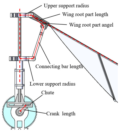
Figure 7.
Flapping rotary mechanism.
To adjust some of the flapping parameters, it is necessary to adjust the transmission form of the crank-chute mechanism and four-bar linkage mechanism by changing transmission parts of them, as shown in Figure 8. Considering the manufacturing difficulty and replacement complexity, the flapping angle and flapping amplitude of the wings can be controlled by replacing the wing root parts and changing the length of connecting bars. The flapping neutral position can be adjusted by changing the spacing between two supports.
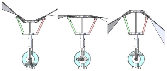
Figure 8.
Changing parts of the mechanism can adjust the related flapping parameters.
3. Experimental and CFD Setup
3.1. Experimental System
The purpose of this experiment is to study the lift effect under different conditions and corresponding flapping frequency, so only the force distribution in the vertical direction needs to be paid attention.
The lift test bench is mainly composed of a flapping wing rotor experimental prototype, a single degree of freedom load cell, a signal amplifier, a high-speed camera, a signal acquisition card, regulated power supply, a computer, and a bench system.
The single degree of freedom load cell can measure the longitudinal force produced in the flapping process of the flapping rotor, namely the lift force. The high-speed camera can record the flapping frequency and rotation speed over a period of time. The above parameters can be measured synchronously in real time to analyze the relationship between them.
The stable bench system can ensure that the flapping wing rotor model can obtain a better clearance condition and reduce the influence of vibration and ground effect. The experimental platform has the advantages of simple principle, high reliability, and strong practicability. The whole experimental system is shown in Figure 9.
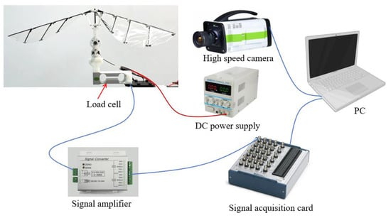
Figure 9.
The flapping wing rotor experimental system.
Since the lifting force of the FWR changes periodically and has peak states, in order to ensure the measurement effectiveness, a single degree of freedom force load cell (AT8509) with a range of 300 g was selected. The obtained voltage signal will pass through a signal amplifier (TDA-06) with a gain of 1000. The amplified signal was transferred to a signal acquisition card (NI USB-6361) before finally being passed to a computer and processed by software LabVIEW (2014, national instrument, Austin, Texas, and America).
The two kinds of regulated power supply are digital DC adjustable. The DC voltage for signal acquisition card and the motor of flapping wing rotor model are 24 V, and 8.4 V, respectively.
The lift test shall avoid the interference of ground effect and side obstacles as far as possible. It is necessary to stay away from the ground and use the support structure with as little impact as possible. Therefore, the test bench is composed of a table top loading fixed end, a ground ballast fixed end, a connecting rod, and a load cell installation base.
The box shaped body is a desktop holding end, which is fixedly connected with the desktop through several D-clips. The bottom is the ground ballast fixed end, on which 20 kg ballast is placed for stability. The distance between the desktop and ground can be changed by adjusting the length of the connecting rod.
3.2. CFD Model and Validation
In order to calculate the flow field of the flapping wing rotor and compare it with the lift obtained by experiment, a CFD model was built. The shape and size of the wing model used in the numerical simulation are the same as the experiment model. The CAD geometry of the computational model and the meshing model is shown in Figure 10. The fluid calculation domain is a cylinder with a diameter of 3 m and a height of 3 m. Based on the dynamic mesh function in Fluent software, the wing motion mode of the FWR was simulated. Unstructured mesh was adopted for simulation calculation, and the total number of meshes was about 1.5 million. Compared with structural mesh, unstructured mesh is easier to adapt to complex geometric structures and more convenient to generating a dynamic mesh. CFD simulations were based on Reynolds-averaged Navier Stokes (RANS) equations combined with SST k-ω turbulence mode [20].
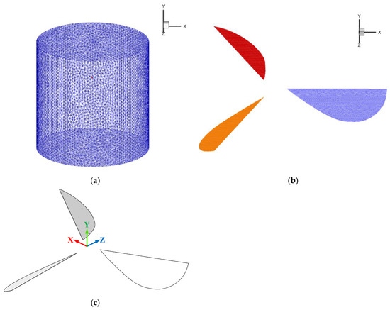
Figure 10.
Mesh used in the CFD calculation: (a) Computational domain of CFD model; (b) Part of computational mesh in wings section; (c) The CAD geometry of the computational model.
In the simulation, the UDF needs to be written to endow the FWR with specific motion mode. When establishing the motion equation of the FWR, the wing is assumed to be a rigid body, so the complex motion of the FWR can be realized by macro command DEFINE_CG_MOTION. This macro is used to specify the rigid body motion. The macro statement can be compiled to specify the real-time angular velocity and linear velocity of the rigid body to achieve complex rigid body motion. The flapping, rotation, and pitch angles of the FWR are defined by Equations (1)–(3).
where φ is the flapping angle, ψ is the rotation angle, α is the pitch angle, fflap is flapping frequency, frot is rotation frequency, and φ0, ∆φ, α0, and ∆α are the midpoint flapping angle, flapping amplitude, initial attack angle, and pitch amplitude, respectively.
In order to verify the effectiveness of the CFD, typical working conditions are selected for verification. Figure 11 shows experiment results corrected by Kalman filtering and CFD results when fflap is 14.5 Hz, frot is 14.2 rps, φ0 is 0°, ∆φ is 70.3°, α0 is 20°, and ∆α is 5°. The experimental result is slightly different from the CFD simulation. The average lift of the CFD simulation is 25.48 g which is 2.79% different from the experimental value of 26.21 g. These differences are mainly due to the limited measurement of the wing motion and especially the real-time passive torsion of the wings.
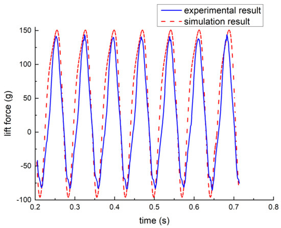
Figure 11.
Comparison of real-time lift results between experiment and CFD.
This is because the influence of aeroelastic effect on aerodynamic force is neglected in CFD analysis due to the assumption of simple harmonic motion and rigid plate wing.
Grid and time step independence tests were also carried out. The independence study used the simulation conditions where fflap is 16.0 Hz, frot is 10.6 rps, φ0 is 0°, ∆φ is 70.3°, α0 is 35°, and ∆α is 8°. Three types of grids and three types of time step sizes were tested, and their settings are provided in Table 1. The results in Figure 12 show that Set-1 and Set-3 were highly similar for different numbers of grids, and the results of Set-1 and Set-4 with different time step sizes were also highly similar. Thus, for efficient computation, the setting of Set-2 was selected for the subsequent simulations.

Table 1.
The five different settings of the grid and time step independence test.
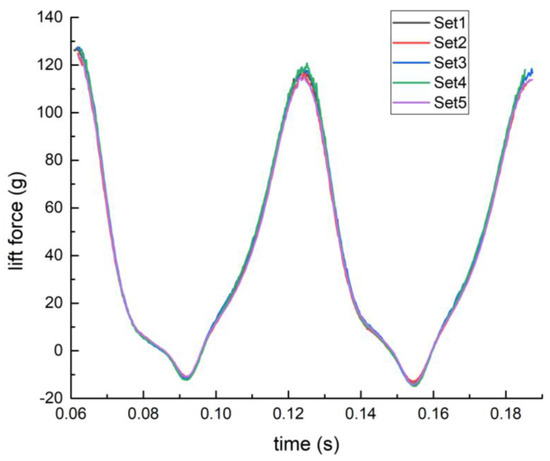
Figure 12.
Comparison of different types of grid numbers and time steps.
In general, CFD and experimental data are in good agreement, which indicates that the computational model used in CFD simulation is of high accuracy. The validations show that the solver is able to accurately simulate FWR wings at flapping-rotation motion and can be used in the CFD calculation for subsequent research.
4. Results and Discussion
4.1. Influence of the Attack Angle of the Wing
The attack angle of the wing varies with the angle between the wing surface and the installation plane of the wing root part. The first FWR which can perform controlled flight used wings with 25° attack angle. In order to explore the influence of wing attack angle, wings with attack angles of 20°, 25°, 30°, 35°, 40°, and 45° were made respectively. The lift test was carried out under the condition of keeping the structure of other parts of the FWR model exactly the same. The flapping frequency-lift force line chart and the flapping frequency-rotation speed line chart are shown in Figure 13.
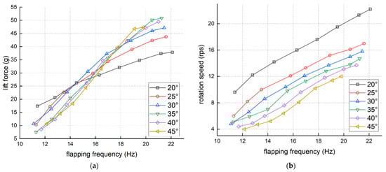
Figure 13.
The influence of wing attack angle of the FWR: (a) The flapping frequency-lift force line chart; (b) the flapping frequency-rotation speed line chart.
From the flapping frequency-lift force line chart, it can be seen that the lift of the FWR is approximately linear with the flapping frequency, and the slope of the line chart increases with the increase of attack angle. When the flapping frequency is lower than 17 Hz, the wing with smaller attack angle shows better lift characteristics, but with the increase of flapping frequency, the growth of wing lift with smaller attack angle slows down, while the wing lift with larger attack angle maintains a large growth. Among them, the wing with attack angle of 35° has the best performance.
From the flapping frequency-rotation speed line chart, the rotation speed of the FWR increases linearly with the increase of flapping frequency, but under the same flapping frequency, the rotation speed decreases with the increase of attack angle. This is because the greater the attack angle when the FWR rotates, the greater the horizontal resistance during rotation, resulting in the decrease of rotation speed.
In order to verify the lift advantage of the wing with attack angle of 35°, CFD simulation was performed on the wing at different attack angles under typical working conditions. The flapping frequency of 18.0 Hz (the three-wing FWR with 25° wings can hover at this flapping frequency in the flight test) was chosen as a basic parameter. The other parameters of wings with different attack angle are shown in Table 2. The rotation speed was taken from the experimental results and endowed the CFD simulation as the corresponding motion mode. Figure 14 shows the lift force of the experiment and CFD results with different attack angle of wing at the flapping frequency of 18.0 Hz.
Table 2.
The parameters of the FWR with different attack angle.
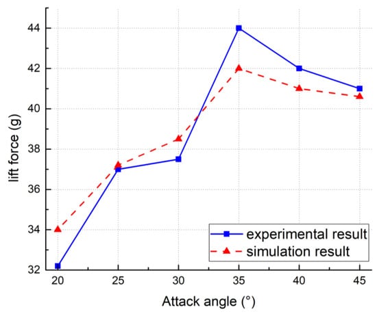
Figure 14.
Lift force of the experiment and CFD results.
The mean absolute percentage error between the experimental result and simulation result is 3.59%. The maximum lift force of the FWR appears at 35° in both experiment and CFD results, which means that the three-wing FWR can achieve the best aerodynamic performance. These results benefit from both the flapping-rotation motion and the aeroelastic effect. The beneficial interference between the wings results in a large jump in lift compared to the 30° wings. As for 40° and 45° wings, the increase of the attack angle weakens the beneficial interaction and slows the rotation speed even more, so there was a drop in lift.
4.2. Influence of the Torsion of Wings
On the basis of the best performance in lift, the wing with attack angle of 35° became the reference model of the torsional wings. The torsional wing used special molds to place auxiliary beams in different planes. The middle auxiliary beam maintains the attack angle of 35°, while the other two auxiliary beams change their attack angles. By setting the torsion direction and torsion angle of 5° and 10°, four kinds of torsional wings were manufactured. 30-35-40°, 40-35-30°, 25-35-45°, and 45-35-30° torsion wings were tested.
The experimental data of 25°, 35° and 45° attack angles are compared with torsion wings. The flapping frequency-lift force line chart and the flapping frequency-rotation speed line chart of wings with 5° torsion angle and non-torsional wings are shown in Figure 15, and wings with 10° torsion angle and non-torsional wings are shown in Figure 16.
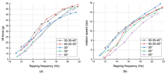
Figure 15.
The influence of 5° wing torsion of the FWR: (a) Flapping frequency-lift force line chart; (b) flapping frequency-rotation speed line chart.
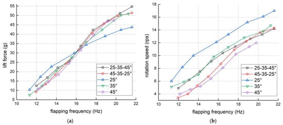
Figure 16.
The influence of 10° wing torsion of the FWR: (a) Flapping frequency-lift force line chart; (b) flapping frequency-rotation speed line chart.
From the line charts above, it can be seen that no matter the magnitude or direction of span wise torsion, it will produce greater lift than the non-torsional wings at higher flapping frequency, and the rotation speed is also close to the wing with 35° attack angle. At lower flapping frequency, the external torsion wings have certain advantages over the internal torsion wings in lift and rotor speed, but with the increase of flapping frequency, the effects of these two tend to be similar.
4.3. Influence of Different Neutral Positions
The wing neutral position of the FWR is determined by relying on the crank being in the horizontal position, as shown in Figure 17. The influence of wing neutral position on the FWR’s performance was studied by adjusting the distance between upper and lower supports at neutral position. The parameters are shown in Table 3. The flapping frequency-lift force line chart of the FWR with different neutral positions is shown in Figure 18. Since changing each value will affect the flapping parameters, it is difficult to adjust the completely equal positive and negative neutral flapping angles. Therefore, two very close values of 10.6° and −10.3° are selected as the inverse ratio, and the difference caused by their different values is within the acceptable range.
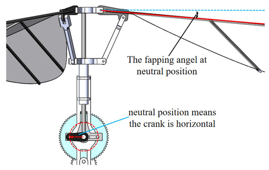
Figure 17.
The wing neutral position of the FWR.
Table 3.
The parameters of the FWR with different neutral positions.
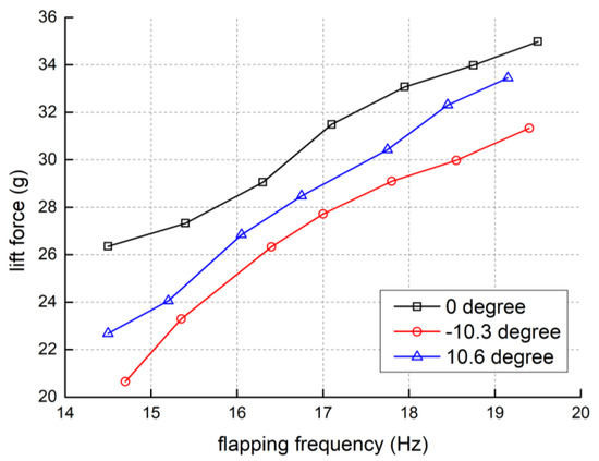
Figure 18.
The flapping frequency-lift force line chart of the FWR with different neutral positions.
It can be seen that the FWR with zero flapping angle at neutral position can produce much more lift force. When at the neutral position, the crank is in a horizontal position, and the flapping down speed is close to maximum. If the wings are close to horizontal at the same time, they have the maximum horizontal projection area, which contributes to the generation of lift force.
4.4. Influence of Different Maximum Angle of Flapping up and down
The maximum angle of flapping up and down are determined by relying on the crank being in the vertical downward and upward position, as shown in Figure 19. When the flapping angle at neutral position is 0 degrees and the total flapping angles are the same, the influence of the different maximum angles of flapping up and flapping down on the FWR’s performance is mainly achieved by changing different combinations of wing root parts and connecting bars, also appropriately adjusting the distance between two supports at the neutral position is needed. The parameters are shown in Table 4. The flapping frequency-lift force line chart of the FWR with different maximum angles of flapping up and flapping down is shown in Figure 20.
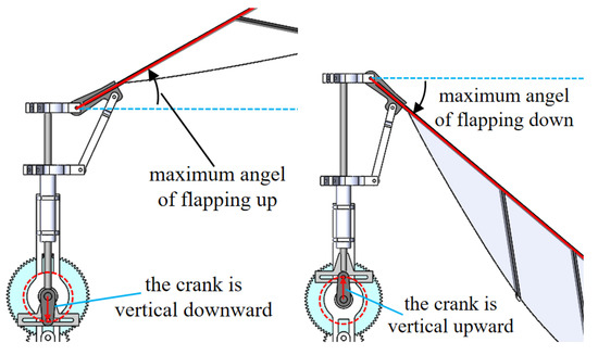
Figure 19.
The maximum angle of flapping up and down.
Table 4.
The parameters of FWR with different maximum angles of flapping up and down.
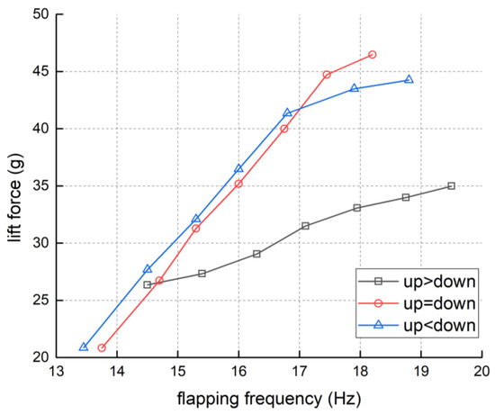
Figure 20.
The flapping frequency-lift force line chart of the FWR with different maximum angles of flapping up and down.
It can be seen from the figure that FWR can produce the most ideal lift force when the angle of flapping up and down are close, and with the increase of flapping frequency, the lift force grows rapidly. As for the down flapping angle nearly 5° larger than the up flapping angle, the lift force slightly weakened and the growth speed has slowed, but the lift force is still in a relatively ideal range. When the up flapping angle nearly 5° larger than the down flapping angle, the lift force drops a lot and the growth speed slows down rapidly.
It can be concluded that the flapping stroke below the middle site plays an important role in the FWR’s lift generation. The reason should be that the flapping stroke below the middle site is more favorable for the flapping wing surface to be loaded and then torsional deformation to produce greater vertical lift. In contrast, the direction of the load and force generated by the flapping stroke above the middle point has limited influence on lift force. In a word, it is best to adjust the maximum angles of flapping up and down to be equal when manufacturing FWRs.
4.5. Influence of Different Flapping Amplitude
To ensure the flapping angle is 0° at neutral position and the angle of up and down flapping are close while study the effect of flapping amplitude on the FWR’s performance, all three values, wing root parts, connecting bar length, and spacing between upper and lower supports, need to be adjusted. All parameters are shown in Table 5. Schematics of the flapping amplitudes of 51.6° and 92.6° are shown in Figure 21. The flapping frequency-lift force line chart of the FWR with different flapping amplitudes is shown in Figure 22.
Table 5.
The parameters of FWR with different flapping amplitudes.
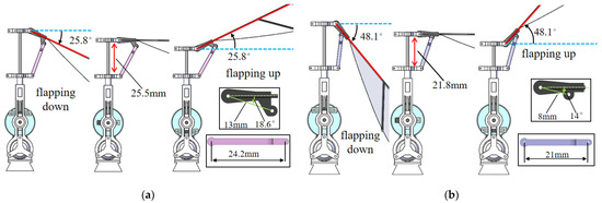
Figure 21.
Schematic of the flapping amplitudes: (a) Flapping amplitude of 51.6°; (b) flapping amplitude of 92.6°.
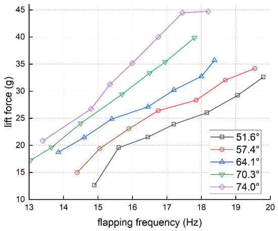
Figure 22.
The flapping frequency-lift force line chart of the FWR with different flapping amplitudes.
The results in Figure 22 show that the lift force increased with the growth of the flapping amplitude in general. With the growth of the flapping amplitude, the slope of the flapping frequency-lift force line increased gradually, which means the flapping effectiveness was improved. At the same time, large flapping amplitude could not achieve high flapping frequency based on this FWR model. It also demonstrates that driving larger flapping amplitude needs more power consumption. Note, the lift force with flapping amplitude of 82.4°, 88.2°, and 96.2° were studied as well. Nevertheless, the transmission structure of the proposed FWR cannot handle such aggressive flapping amplitudes. In fact, as flapping amplitude exceeds 80°, it is highly possible to damage the transmission mechanisms, causing few effective data.
Based on the experimental data that were obtained and considering the large power consumption caused by large flapping amplitude, a flapping frequency of 16 Hz was selected as the comparison condition. First, two flapping cycles with flapping amplitudes of 51.8°, 74.0°, and 88.2° were selected with the same passive torsion angle of the wing, as shown in Figure 23.
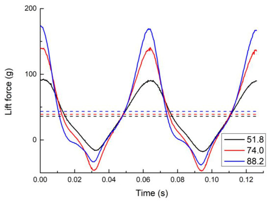
Figure 23.
The flapping frequency-lift force line chart of three different flapping amplitudes with the same passive torsion angle.
In Figure 23, the solid lines are the actual lift data measured by experiments, and the dashed lines are the corresponding average lift forces. It is not difficult to see that the maximum value of the lift force to becomes higher while the flapping amplitude becomes larger. However, the average lift force variation of different flapping amplitudes is much smaller than the actual experimental measurement.
The passive torsion angle is corrected by reference to the high speed camera, and the CFD simulation results are close to the experimental results at this time. Figure 24 shows the experimental and CFD results of the FWR with different flapping amplitudes at 16 Hz flapping frequency.
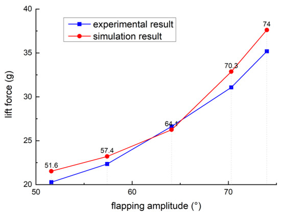
Figure 24.
The flapping amplitude-lift force of the experiment and CFD results with different flapping amplitudes.
As can be seen from the figure, the CFD simulation value after passive torsion angle correction is highly consistent with the experimental value. The flapping amplitude increased from 51.6° to 74°, and the experimental and CFD results gradually increased from 20 g to 35 g, which was consistent with the conclusion in the literature [18], and the growth rate also kept increasing. The mean absolute percentage error between the experimental result and simulation result is 5.06%. A larger flutter amplitude will produce a larger lift force, which is completely applicable to the FWR. Consequently, once the strength limitation of the transmission structure can be addressed, the lift can be further improved by keeping increasing the flapping amplitude.
It can be concluded that the increase of flapping amplitude will mainly cause greater changes in the passive torsion angle and then generate greater average lift force. Meanwhile, the increase of flapping amplitude will also lead to increase of lift force peak, which largely leads to damage of the FWR experiment model. Therefore, while increasing the flapping range of the FWR aircraft to improve lift, the load capacity of the transmission mechanism should also be considered realistically.
5. Conclusions
Through experiments and CFD simulation, the influence of five different flapping parameters on the FWR was studied. This provides improvement direction and a production evaluation standard for the first FWR-MAV with powered flight. This enables subsequent FWR-MAVs to fly with more loads. The main results are summarized as follows:
- As the attack angle of the wing increases, the rotation speed of the wing decreases, the lift force increases first and then decreases, and the maximum lift of the wing appear at 35°.
- Based on the wing with attack angle of 35°, and setting the torsion direction and torsion angle of 5° and 10°, four kinds of torsional wings were manufactured and experimented. The result showed that all the torsional wings produce a little more lift than the non-torsional wings, but the overall performance was similar to the base wing with attack angle of 35°, and its manufacturing difficulty also increased.
- The FWR with flapping angle of 0° at neutral position can produce the most lift force, which means the flapping down wings can obtain the maximum horizontal projection area near the maximum speed.
- From the research of different maximum angles of flapping up and down, it can be found that the FWR can produce the most ideal lift force when the angles of up and down flapping are close to each other, and the down flapping angle played a more important role than the up flapping angle in the lift force production.
- With the growth of the flapping amplitude, the lift force increases continuously. This is mainly due to the greater changes in the passive torsion angle of wings caused by the aerodynamics. At the same time, the increase of lift force peak will cause a large load on the transmission, which may cause damage to the FWR mechanism.
The experimental study and CFD simulation in this paper is based on the three-wing FWR at this scale. Due to the limitation of motor power, the experimental study cannot set a specific flapping frequency value, and the CFD simulation does not change along the spread direction as it does in the actual passive torsion deformation. In the future, as the FWR’s lift improves, it will be loaded with larger loads for more flight tests and related studies. On the other hand, the study of flapping-rotation motion forms based on controllable three-wing FWR-MAVs will also be carried out.
Author Contributions
Conceptualization, D.L.; methodology, Z.W. and Z.T.; software, Z.K. and H.L.; validation, Z.W. and H.L.; formal analysis, Z.W.; investigation, Z.K.; resources, H.L.; data curation, Z.W. and H.L.; writing—original draft preparation, Z.W.; writing—review and editing, S.Z. and Z.T.; visualization, H.L.; supervision, S.Z.; project administration, Z.W. and D.L.; funding acquisition, D.L. All authors have read and agreed to the published version of the manuscript.
Funding
This research was funded by the National Natural Science Foundation of China, grant numbers 52102431 and 11972059.
Institutional Review Board Statement
Not applicable.
Informed Consent Statement
Not applicable.
Data Availability Statement
Not applicable.
Acknowledgments
The authors gratefully acknowledge the support of the National Natural Science Foundation of China. In addition, our thanks are given to the editors and reviewers for contributing to the final form of this research.
Conflicts of Interest
The authors declare no conflict of interest.
References
- Zbikowski, R. Fly like a fly [micro-air vehicle]. Spectr. IEEE 2005, 42, 46–51. [Google Scholar] [CrossRef]
- Keennon, M.T.; Grasmeye, J.M. Development of the black widow and microbat mavs and a vision of the future of mav design. Dayt. AIAA 2003. [Google Scholar]
- Wilson, T.J. MicroStar Meets Mav; Aerospace America: Bay City, MI, USA, 1999; pp. 32–35. [Google Scholar]
- Airborne Personal Reconnaissance System (PRS) for Dismounted Soldiers. Available online: https://www.flir.com/products/black-hornet-prs/ (accessed on 24 August 2019).
- Lentink, D. Biomimetics: Flying like a fly. Nature 2013, 498, 306–307. [Google Scholar] [CrossRef]
- Mishra, S.; Tripathi, B.; Garg, S.; Kumar, A.; Kumar, P. Design and Development of a Bio-Inspired Flapping Wing Type Micro Air Vehicle. Procedia Mater. Sci. 2015, 10, 519–526. [Google Scholar] [CrossRef]
- Kim, D.K.; Han, J.H.; Kwon, K.J. Wind tunnel tests for a flapping wing model with a changeable camber using macro-fiber composite actuators. Smart Mater. Struct. 2009, 18, 24–32. [Google Scholar] [CrossRef]
- Phan, H.V.; Kang, T.; Park, H. Design and stable flight of a 21 g insect-like tailless flapping wing micro air vehicle with angular rates feedback control. Bioinspir. Biomim. 2017, 12, 036006. [Google Scholar] [CrossRef] [PubMed]
- Tu, Z.; Fei, F.; Zhang, J.; Deng, X. An At-Scale Tailless Flapping-Wing Hummingbird Robot. I. Design, Optimization, and Experimental Validation. IEEE Trans. Robot. 2020, 36, 1511–1525. [Google Scholar] [CrossRef]
- Ma, K.Y.; Chirarattananon, P.; Fuller, S.B.; Wood, R.J. Controlled flight of a biologically inspired, insect-scale robot. Science 2013, 340, 603–607. [Google Scholar] [CrossRef] [PubMed]
- Jafferis, N.T.; Helbling, E.F.; Karpelson, M.; Wood, R.J. Untethered flight of an insect-sized flapping-wing microscale aerial vehicle. Nature 2019, 570, 491–495. [Google Scholar] [CrossRef] [PubMed]
- Wagter, C.D.; Tijmons, S.; Remes, B.D.W. Autonomous flight of a 20-gram flapping wing MAV with a 4-gram onboard stereo vision system. In Proceedings of the IEEE International Conference on Robotics and Automation (ICRA), Hong Kong, China, 31 May–7 June 2014. [Google Scholar]
- Karásek, M.; Muijres, F.T.; De Wagter, C.; Remes, B.D.W.; de Croon, G.C.H.E. A tailless aerial robotic flapper reveals that flies use torque coupling in rapid banked turns. Science 2018, 361, 1089–1094. [Google Scholar] [CrossRef] [PubMed]
- Guo, S.; Yang, D.; Kummari, K.L.; Huang, Z. A smart material flapping wing micro rotorcraft. In Proceedings of the International Committee on Composite Materials (ICCM), Edinburgh, UK, 27–31 July 2009. [Google Scholar]
- Zhou, C.; Wu, J.; Guo, S.; Li, D. Experimental study on the lift generated by a flapping rotary wing applied in a micro air vehicle. Proc. Inst. Mech. Eng. Part G J. Aerosp. Eng. 2014, 228, 2083–2093. [Google Scholar] [CrossRef]
- Li, H.; Guo, S. Aerodynamic efficiency of a bioinspired flapping wing rotor at low Reynolds number. R. Soc. Open Sci. 2018, 5, 171307. [Google Scholar] [CrossRef] [PubMed]
- Li, H.; Guo, S.; Zhang, Y.L.; Zhou, C.; Wu, J.H. Unsteady aerodynamic and optimal kinematic analysis of a micro flapping wing rotor. Aerosp. Sci. Technol. 2016, 63, 167–178. [Google Scholar] [CrossRef]
- Wu, J.; Wang, D.; Zhang, Y. Aerodynamic analysis of a flapping rotary wing at a low Reynolds number. AIAAJ 2012, 23, 429–438. [Google Scholar] [CrossRef]
- Wang, D.; Zhang, Y.; Wu, J.; Zhang, Y. Aerodynamics on Flapping Rotary Wing in Low Reynolds Number. Am. Inst. Aeronaut. 2013, 37, 1–14. [Google Scholar]
- Shao, H.Y.; Li, D.C.; Kan, Z.; Li, H.D. Influence of wing camber on aerodynamic performance of flapping wing rotor. Aerosp. Sci. Technol. 2021, 113, 106732. [Google Scholar] [CrossRef]
- Yi, S.; Li, D. Design and experimental study of a new flapping wing rotor micro aerial vehicle. In Proceedings of the 2017 IEEE International Conference on Unmanned Systems (ICUS), Beijing, China, 27–29 October 2017. [Google Scholar]
- Dong, X.; Li, D.; Xiang, J.; Wang, Z. Design and experimental study of a new flapping wing rotor micro aerial vehicle. Chin. J. Aeronaut. 2020, 33, 3092–3099. [Google Scholar] [CrossRef]
Publisher’s Note: MDPI stays neutral with regard to jurisdictional claims in published maps and institutional affiliations. |
© 2022 by the authors. Licensee MDPI, Basel, Switzerland. This article is an open access article distributed under the terms and conditions of the Creative Commons Attribution (CC BY) license (https://creativecommons.org/licenses/by/4.0/).